1
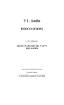
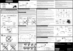
®
TLAudio
user manual
Ivory 2 Series
5013
DUAL VALVE EQUALISER
TL Audio Ltd, Letchworth, Herts, SG6 1AN, UK
email: [email protected] web: http://www.tlaudio.co.uk
CONTENTS
1
INTRODUCTION
2
PRECAUTIONS
3
INSTALLATION
3.1
3.2
3.3
3.4
3.5
3.6
3.7
3.8
3.9
AC Mains Supply
Audio Operating Level
Balanced Line Input
Unbalanced Line Input
Instrument Input
Balanced Output
Unbalanced Output
Mounting
Rear Panel
4
OPERATION
4.1
4.2
4.3
4.4
4.5
4.6
4.7
4.8
4.9
4.10
4.11
4.12
Front Panel
Line Input
Instrument Input
Drive and Peak LEDs
Equalisation
Cut/Boost Control
Frequency Control
Q (Bandwidth) Control
Shelving EQ
Fat Contour Switch
Output Level
Optional DO-2 Digital Output Card
5
GETTING STARTED
6
SPECIFICATIONS
7
SERVICE
1. INTRODUCTION
Congratulations on purchasing the Ivory 5013 Dual Valve Equaliser by TL
Audio! The T L Audio Ivory 2 Series consists of a range of hybrid valve signal
processors, which utilise low noise solid state electronics in conjunction with
classic valve circuitry to produce audio processing units offering very high
quality signal paths with the unique valve audio character. The Ivory 2 Series
units offer comprehensive control facilities, whilst remaining straightforward to
operate, and represent excellent value for money.
The 5013 is a stereo parametric valve equaliser featuring four fully variable EQ
bands on each channel. The block diagram of one of the channels is shown in
Fig.1. The balanced line input is via an XLR socket, whilst the unbalanced
connection is via a 0.25” jack socket. The nominal input levels are +4dBu on
the balanced connections and -10dBu on the unbalanced connections, but
these may be shifted to +18dBu and +4dBu respectively by the rear panel
input level switch. This feature offers greater flexibility of connection to other
equipment, particularly the latest generation of digital recorders which operate
at very high signal levels. The line inputs have an overall gain range of -20 to
+20dBu.
The front panel instrument jack sockets allow direct access to the channel
inputs. The instrument inputs eliminate the need to use external DI (Direct
Injection) boxes as they are suitable for a variety of sources, including electric
guitars, bass guitars, acoustic pickups, synths, samplers and drum machines.
The instrument input level is controlled by the 5013 input gain control. The
input level is monitored by both “Drive” and “Peak” LEDs: Drive is a variable
intensity LED designed to indicate the signal level through the valve stages,
and thus the amount of “warming” applied to the signal. Peak is a conventional
warning that clipping is about to occur, and will illuminate if there is an
excessively high level present not just at the input but at any point in the signal
chain.
Both channels feature a four band parametric equaliser, with each band
providing variable frequency, gain and Q (bandwidth) controls. The LF and HF
sections include options for shelving or peaking response by means of a pullout Q control. Pulling the Q control knob ‘out’ converts the section to a
shelving type equaliser, with the Q control then becoming inactive. The ‘FAT’
contour switch provides a subtle but effective LF and HF lift while at the same
time reducing the gain in the mid range - this filtering provides a perceptible
increase in warmth without altering the overall signal volume.
The master output level controls are post-EQ. These controls are centredetented for ease of line-up, but may be varied in conjunction with the input
gain controls to alter the operating level through the circuitry, optimising the
operating level and hence headroom and signal to noise ratio of the unit. It is
possible to push the input levels harder to drive the valve stages and
compensate by turning down the output gain. Alternatively the input gain can
be kept low for a cleaner sound and the output gain can be turned up to
compensate. This way a wide range of tonal colours is achievable.
The line output is via balanced XLR socket at a nominal level of +4dBu, with
an unbalanced output on 0.25” jack at a nominal level of -10dBu. As with the
input level switch, an output operating level switch is located on the rear panel
allowing either +4dBu or +18dBu for balanced connections and –10dBu or
+4dBu for unbalanced connections, thus matching both outputs with a wide
variety of equipment.
The optional DO-2 24 bit digital output card provides A-D conversion of the
5013’s outputs, outputted in SPDIF format with switchable 44.1/48kHz sample
rate. A BNC wordclock input is also provided.
Please read this manual fully before installing or operating the 5013 Equaliser.
2.
PRECAUTIONS
The 5013 Equaliser requires very little installation, but like all electrical
equipment, care must be taken to ensure reliable, safe operation. The
following points should always be observed:
- All mains wiring should be installed and checked by a qualified
electrician,
- Ensure the correct operating voltage is selected on the rear panel
before connecting to the mains supply,
- Never operate the unit with any cover removed,
- Do not expose to rain or moisture, as this may present an electric
shock hazard,
- Replace the fuse with the correct type and rating only.
Warning: This equipment must be earthed.
3.
INSTALLATION
3.1
AC Mains Supply.
The unit is fitted with an internationally approved 3 pin IEC connector. A
mating socket with power cord is provided with the unit, wired as follows:
Brown: Live.
Blue:
Neutral.
Green/Yellow: Earth (Ground).
All mains wiring should be performed by a qualified electrician with all power
switched off, and the earth connection must be used.
Before connecting the unit to the supply, check that the unit is set for the
correct mains voltage. The unit is internally set for 110-120V 60Hz or 220240V 50Hz operation, and should only be changed by an authorised service
centre. The mains fuse required is 20mm anti-surge, 1AT rated at 250V. If it is
ever necessary to replace the fuse, only the same type and rating must be
used. The power consumption of the equipment is 20VA.
Warning:
3.2
attempted operation on the wrong voltage setting, or with an
incorrect fuse, will invalidate the warranty.
Audio Operating Level.
The 5013 is equipped with inputs and outputs suitable for connection to a wide
variety of other audio equipment. Generally, the balanced XLR connections
will be required for interfacing to other professional equipment, where the
operating level (line-up level or nominal level) will be +4dBu, or approximately
1.2V rms. The unbalanced jack connectors are generally intended for
interfacing to semi-professional equipment and have an operating level of 10dBu, or about 225mV rms. However, the input and output level switches
allow these levels to be shifted by 14dB, i.e. to +18dBu on the XLRs (suitable
for high levels from a digital machine), and +4dBu on the unbalanced jacks.
The normal default mode would be the +4dBu balanced setting, but if upon
feeding a digital multitrack machine into the 5013 line inputs - clipping occurs
even on low input gain settings, then the +18dBu setting should be used.
Similarly, If the line output of the 5013 is fed into a digital multitrack input and
very large amounts of 5013 output gain are necessary to register 0dBfs on the
recorder, the +18dBu setting should be used, allowing the 5013 output gain to
be set at a more conservative level.
The 5013 may be used to shift operating levels, for example by connecting the
unbalanced output of a semi-pro mixing console to the equaliser’s unbalanced
input, and taking the balanced output of the equaliser to the balanced input of
a tape machine at +4dBu. All line-level inputs and outputs of the equaliser may
be used simultaneously if required. Balanced interconnection is always
preferable to obtain the best headroom and noise rejection, but can only be
used effectively if the other equipment in the chain, e.g. the mixing console,
also has provision for balanced connections.
3.3
Balanced Line Input.
The line level input is via a 3 pin female XLR connector, suitable for balanced
or unbalanced line sources at a nominal level of +4dBu. The mating
connector should be appropriately wired as follows for balanced or unbalanced
operation:
Balanced inputs:
- Pin 1 = Ground (screen).
- Pin 2 = Signal Phase (also known as “+” or “hot”).
- Pin 3 = Signal Non-Phase (“-” or “cold”).
Unbalanced inputs:
- Pin 1 = Ground (screen).
- Pin 2 = Signal Phase (“+” or “hot”).
- Pin 3 = Signal Ground.
When using unbalanced signals into the balanced XLR input, the signal
ground may be obtained by linking pins 1 and 3 in the mating XLR connector.
If this connection is not made, a loss in level may result.
3.4
Unbalanced Line Input.
An unbalanced line level input at a nominal level of -10dBu is also provided,
on a 0.25” mono jack socket. The mating plugs should be wired as follows:
- Tip
= Signal Phase (“+” or “hot”).
- Screen = Ground.
3.5
Instrument Input.
A 2-pin (mono) jack plug is required, which should be wired as follows:
- Tip = Signal Phase (“+” or “hot”).
- Screen = Ground.
The instrument input is suitable for direct connection of instruments including
guitars and keyboards. Good quality screened cable should be used,
particularly for microphone or low level sources, to prevent hum or noise
pickup.
3.6
Balanced Output.
The output is via a balanced, 3 pin male XLR connector. The mating connector
should be wired as follows:
- Pin 1 = Ground (screen).
- Pin 2 = Signal Phase (“+” or “hot”).
- Pin 3 = Signal Non-Phase (“-” or “cold”).
3.7
Unbalanced Output.
An unbalanced line output is provided for each channel, on a 0.25” mono jack
socket.
- Tip =
Signal Phase (“+” or “hot”).
- Screen = Ground.
3.8
Mounting.
The equaliser may be free standing, or mounted in a standard 19” rack.
Always ensure that the cooling vents on the front and sides are clear of
obstruction, and do not subject the unit to an external source of heat (by
mounting immediately above a power amplifier, for example). If used free
standing, ensure that the equipment is protected against rain and spillage of
liquid.
3.9
Rear Panel.
The rear panel connectors are identified in Fig.3. Make sure that all settings,
mains and audio connections have been made as described above before
attempting to operate the equipment.
4.
OPERATION
4.1
Front Panel.
The front panel controls are identified in Fig.2.
4.2
Line Input.
A line level signal should already be at about the correct operating level, but
check that the input level switch is correctly set (see section 3.2). An input gain
adjustment may be made if necessary.
4.3
Instrument Input.
The front panel instrument input socket is suitable for low-level sources such
as dynamic microphones, pick-ups or passive guitars and higher level sources
such as active guitars and keyboards. The instrument gain is controlled by the
5013 input gain control. Due to the wide range of the input, a high level of gain
is available in the equaliser, and care should be taken not to apply excessive
input gain to a high level signal. Please note also that the instrument input is
not designed to accept the output of a power amplifier, such as that from a
guitar backline amp.
4.4
Drive and Peak LEDs.
The yellow Drive LED provides a visual indication of the signal level through
the valve stages, and therefore the extent of “warming” or valve character
being introduced. The drive LED will gradually illuminate as the input level or
gain is increased, over the range 0dB to +12dB.
The red Peak LED operates as a conventional warning that clipping is about to
occur. The operating level of the entire signal chain is monitored, and the LED
illuminates when there is less than 5dB of headroom remaining. Normal
FIG 2: FRONT PANEL
OUTPUT LEVEL CONTROL
INPUT GAIN CONTROL
0
1
EQ BYPASS SWITCH
0
Hz
Q
100
0
300
Hz
Q
300
Hz
0
2K
1K
Q
Hz
0
6K
EQ
Q
6K
0
12K
FAT
-20
dB +20
DRIVE
IVORY
-15
dB +15
30
INPUT
INSTRUMENT
PEAK
0
2
0
1K
-15
LF
(PULL)
Hz
Q
100
dB +15
100
-15
3K
dB +15
1K
0
300
12K
-15
dB +15
3K
HM
LM
Hz
300
Hz
0
Q
2K
1K
Q
0
6K
-20
20K
HF
(PULL)
Hz
Q
6K
ON
ON
dB +20
OUTPUT
5013
0
DUAL VALVE
EQUALISER
EQ
12K
FAT
-20
dB +20
-15
dB +15
30
INPUT
INSTRUMENT
DRIVE
1K
LF
PEAK
INSTRUMENT INPUT
-15
dB +15
100
-15
3K
dB +15
1K
12K
-15
dB +15
HM
LM
(PULL)
SHELVING SWITCH
(BY PULLING OUT Q CONTROL)
3K
-20
20K
HF
(PULL)
dB +20
OUTPUT
ON
ON
POWER
Q CONTROL
MAINS POWER SWITCH
FREQUENCY CONTROL
‘FAT’ CONTOUR SWITCH
CUT/BOOST CONTROL
FIG 3: REAR PANEL
SAMPLE RATE SELECTOR SWITCH (OPTIONAL)*
DIGITAL OUTPUT (OPTIONAL)*
WARNING - ATTENTION
W/CLOCK INPUT (OPTIONAL)*
SPDIF OUTPUT
THIS APPARATUS MUST BE EARTHED.
FOR CONTINUED PROTECTION
AGAINST RISK OF FIRE, REPLACE ONLY
WITH SAME TYPE AND RATING OF FUSE.
CAUTION
W/CLOCK
IN
44.1
Manufactured by TL Audio Limited, England.
RISK OF ELECTRIC SHOCK
DO NOT OPEN
ATTENTION
kHz
48
RISQUE DE CHOC ELECTRONIQUE
NE PAS OUVRIR
5013 DUAL VALVE EQUALISER
SERIAL NUMBER
UTILISER UN FUSIBLE DE RECHANGE DE
MEME TYPE ET CALIBRE
CHANNEL 2 OUTPUT
FUSE T1AL 250V
230V~25VA
115V~25VA
JACK: TIP = +VE, SLEEVE = GND.
OUTPUT
LEVEL
+4dBu
+18dBu
-10dBu
+4dBu
+4dBu
+18dBu
BALANCED LINE OUTPUT
UNBALANCED LINE OUTPUT
* VIA DO-2 DIGITAL OUTPUT CARD
CHANNEL 2 INPUT
CHANNEL 1 INPUT
WARNING
TO REDUCE THE RISK OF FIRE
OR ELECTRICAL SHOCK,
DO NOT EXPOSE THIS EQUIPMENT
TO RAIN OR MOISTURE
XLR: PIN 1 = GND, PIN 2 = +VE, PIN 3 = -VE.
IEC INLET
CHANNEL 1 OUTPUT
-10dBu
+4dBu
OUTPUT LEVEL SWITCH
INPUT
LEVEL
-10dBu
+4dBu
INPUT LEVEL SWITCH
+4dBu
+18dBu
-10dBu
+4dBu
+4dBu
+18dBu
BALANCED LINE INPUT
UNBALANCED LINE INPUT
operation would be to set the input gain so that the drive LED is regularly
illuminating, with occasional lighting of the red Peak LED on transients.
If the input and output gain controls are set to their centre (0dB) positions and
there is no EQ boost applied, the Peak LED will illuminate some 8dB after the
Drive LED has reached its full intensity. However, it is possible to add gain
further down the chain (EQ boost or output level gain), which will cause the
Peak LED to illuminate at a lower level of Drive. This situation implies that a
high level of “clean” signal is present, without driving the valves hard.
Remember that it is possible to apply huge amounts of gain to the input signal,
since all four bands have up to 15dB of gain available - in addition to both
input and output gain controls. If a large amount of EQ is applied on one or
more bands the Peak LED can be easily lit, and in this case you will need to
compensate by easing back on the output gain control.
4.5
Equalisation.
Before switching the EQ into circuit, it is advisable to set the cut/boost controls
to their centre, or flat, position. Each channel of EQ is brought into circuit with
the overall “EQ-ON” push switch positioned to the far right of the unit. A green
LED signals “EQ-ON”.
The four bands of EQ per channel are labelled as LF (low frequency), LM and
HM (low and high mid frequency) and HF (high frequency). However, the
frequency variation available on each band allows overlapping of two, or more,
bands into the same frequency range. This arrangement allows maximum
flexibility, permitting reduction of a narrow band whilst simultaneously boosting
an overlapping broader band of frequencies, for example. Used individually or
in combination, the filter bands allow comprehensive equalisation of any audio
signal.
The typical response curves and the effect of the control setting variations are
shown in the specification section of this manual. The 5013 has a notably wide
bandwidth of 10Hz to 40KHz.
4.6
Cut/Boost Control.
Each of the four EQ bands has a +/- 15dB gain control that is used to apply
cut or boost at the frequency selected by the Frequency control. Often, EQ-ing
is as much about cutting frequencies as it is about boosting them, and
removing excessive bass or mid frequencies from signals to help them sit
better in the mix is a common recording technique. On the other hand TL
Audio EQs are renowned for being very musical - and very forgiving - so you
may find yourself being able to apply a lot more boost than other EQs, and the
sound will still retain its quality and not be destroyed - as is often the case on
cheap or poorly designed EQ sections, particularly when pushed hard.
4.7
Frequency Control.
This control sets the Frequency on each band that is to be cut or boosted. The
frequencies are variable over the following ranges:
LF band:
LM band:
HM band:
HF band:
4.8
30Hz to 1kHz
100Hz to 3kHz
1kHz to 12kHz
3kHz to 20kHz
Q (Bandwidth) Control.
The “Q” of the filter is a measure of the shape of the frequency response
curve, and is closely related to the ‘bandwidth’ or range of frequencies
controlled by the filter. A narrow bandwidth (high Q) setting means that a tight
band of frequencies either side of the selected centre frequency is affected by
any cut or boost actions, while a wide bandwidth (low Q) affects a much
broader band of frequencies.
As a result, high Q settings (about 5 at the maximum setting on the 5013) are
generally used for audio correction or effects - for instance when a single
troublesome frequency needs to be removed without upsetting the rest of the
frequency spectrum, or a single frequency needs to be boosted to create a
particular unique sound. A proven technique for identifying frequencies is to
set the Q control to its minimum (narrow) position, apply a reasonable amount
of boost in that EQ band, and then sweep the Frequency control around until
the problem (or desired) frequency is found (since boosting will make the
frequency prominent). Cut (rather than boost) can then be applied if the
frequency is troublesome, and if necessary the Q can be widened to take out
a broader band of frequencies.
Intermediate Q settings, say 1 to 3, are generally used to enhance or reduce a
broader range of frequencies, typically to make an instrument or vocal stand
out - or recede - into the mix. Finally, low Q values (down to about 0.5 on the
5013) provide gentler contouring, or “sweetening” of the response.
4.9
Shelving EQ.
The low frequency and high frequency sections offer either peaking or
shelving equalisation by means of a pull-out switch on the Q control. When the
knob is pulled ‘out’ the Q control itself becomes inactive and the section will
process any frequencies below the selected frequency (in the LF band) or
above the selected frequency (in the HF band) with a slope of 12dB per
octave. Shelving EQ can be used to “roll-off” low or high end frequencies or to
boost all frequencies above or below the one selected by the variable
frequency control. This can be effective for “warming up” the low frequencies
or adding brightness or “air” to the top end frequencies.
4.10
Fat Contour Switch.
Each channel of the 5013 has a “FAT” contour switch positioned to the far
right of the unit, indicated by a red LED. The Fat switch adds a subtle boost to
the low end and high end frequencies with a slight mid range dip - meaning
the overall volume is not altered. The effect of this is to “sweeten” the signal in
a similar manner to the “boom and fizz” effect of many Hi-Fi speakers. The Fat
switch can be used on any signal or to “fatten-up” an entire mix, and may be
used in conjunction with the rest of the EQ controls.
4.11
Output Level.
The output level control is centre-detented for 0dB gain, with +/-20dB of gain
available. The additional gain may be useful if the output of the equaliser is
connected directly to a digital recorder that requires a high level of modulation.
Note that applying additional gain at the output will not increase the dynamic
range of the signal, but will increase the noise level as well as the audio signal
being recorded, and should therefore only be used if an output level in excess
of the nominal +4dBu is required.
4.12
Optional DO-2 Digital Output Card.
The 5013 is designed to accept the optional D0-2 24 bit digital A to D
converter card to allow easy interfacing of the 5013 with devices such as
sound cards and digital recorders. The card feeds the converted output signals
of channels 1 and 2 to the SPDIF phono output. The sample rate is switchable
between either 44.1kHz or to 48kHz, and the card can be clocked to an
external digital source via the BNC wordclock input. When clocking the DO-2
to an external source the sample rate setting on the DO-2 needs to be set to
match the external sample rate, otherwise correct locking may not occur and
audible clicking may appear on the digital output. In terms of gain, the DO-2
will generate a signal level of 0dBfs in the digital domain when +18dBu of
output level is generated at the balanced line output of the 5013.
5.
GETTING STARTED
Having connected the 5013 checking that the operating level switch is at the
most suitable setting (see section 3.2), it’s time to put it into action! Here’s a
simple step-by-step guide:
1. The first stage is to set up the gains of the unit. With the EQ section
switched out, start with the input and output gains at 0dB.
2. Adjust the input gain so that the Drive LED illuminates with the chosen
source material. You should notice an audible change in sound
character as the input gain is driven harder and the valves start to
generate more harmonics.
3. If more output is then required then adjust the output level control
accordingly. Beneath the input gain there is a red “Peak” LED. This
lights up to warn that the signal is 5dB below clipping. This LED
monitors both the input stage and the output stage. If the Peak LED is
lit when the output gain is very low, then this means the input gain may
be set too high. Alternatively if the LED lights up when the input gain is
low, then the output level control is too high. The normal gain setting
would be such that the Drive LED is illuminating regularly (indicating
that the valve stages are being driven correctly) with occasional lighting
of the Peak LED on transients. Because the Peak LED illuminates 5dB
before clipping, there is still headroom available before distortion
occurs, so don’t be too afraid of seeing this LED active - just trust your
ears!
4. With each EQ band set ‘flat’ (i.e. no cut or boost applied to any band)
activate the EQ-ON switch. Starting with any band you can then
familiarise yourself with the three controls: Gain, Frequency and Q.
Section 4.8 outlines a common technique of identifying frequencies,
and with the Q control at its narrowest the effect of each band will be
most pronounced. You’ll see how broadening the Q value will make the
sound a little more rounded and musical - hence the use of broad Q
values of general sweetening and narrow Qs for more serious surgery!
5. The addition of significant boost in one or more EQ bands can provoke
the Peak LED to
illuminate - remember that there is a huge amount
of gain potentially available - so in this case
reduce the output level
control to compensate.
6. The ‘FAT’ contour switch can be activated, and you should be able to
notice a subtle but effective lifting of the LF and HF - almost like the
‘Loudness’ button on some hi-fi units. This effect can be used on its
own as a general purpose sweetener, or used in conjunction with the
other EQ controls.
6.
SPECIFICATIONS
Line Inputs:
Balanced XLR, switchable +4dBu/+18dB nominal
level. Unbalanced jack, switchable -10dBu/+4dB
nominal level.
Instrument Input:
Front panel jack, Input Impedance 1Mohm.
Input Gain Range:
+/-20dB (Line), -2dB to +38dB (Instrument).
Maximum Input Level:
+30dBu (XLR), +26dBu (Jack), +10dBu
(Instrument).
Outputs:
Balanced XLR, switchable +4dBu/+18dB nominal
level.
Unbalanced jack, switchable -10dBu/+4dB nominal
level.
Output Gain Range:
+/-20dB.
Maximum Output Level: +26dBu (XLR), +12dBu (Jack).
Frequency Response:
+0, -1dB, 10Hz to 40KHz.
Equaliser:
4 band fully parametric, with overall “EQ ON”
switch.
LF Band:
+/-15dB at 30Hz to 1KHz.
Q variable 0.8 to 7.
Switchable to shelving mode.
LM Band:
+/-15dB at 100Hz to 3KHz.
Q variable 0.8 to 7.
HM Band:
+/-15dB at 1KHz to 12KHz.
Q variable 0.8 to 7.
HF Band:
+/-15dB at 3KHz to 20KHz.
Q variable 0.8 to 7.
Switchable to shelving mode.
“FAT” Response:
Predefined EQ contour, maximum +/-3dB, 10Hz to
40KHz.
Distortion:
Predominately second harmonic, increasing with
“Drive” level. Typically 0.5% @ 0dBu.
Drive LED:
Increasing intensity to reflect valve drive,
commencing at +4dBu to full brightness at +14dBu
(Output Level at 0dB).
Peak LED:
+20dBu. Monitors Input, Post EQ and Output
Levels.
Noise:
-82dB, ref +4dBu Input and Output, EQ ON with all
controls centred.
Dynamic Range:
106dB.
Power Requirements:
Internally set to 230V 50Hz or 115V 60Hz
operation.
Detachable IEC power cord.
Consumption 25VA.
Dimensions:
19” Rack mounting, 2U high.
W x D x H = 483 x 200 x 88mm (19.0” x 7.9” x
3.5”).
Shipping Weight:
6kg.
The above specifications are typical figures, and are subject to change without notice.
7.
SERVICE
Should the 5013 require service, it must be taken or posted to an authorised
dealer. Please retain the original packing for possible future use, and ensure
the unit is suitably protected during transit. The manufacturer cannot accept
responsibility for damage caused during transportation.
The 5013 is supported by a limited warranty for a period of one year from the
date of purchase. During this period, any faults due to defective materials or
workmanship will be repaired free of charge. The warranty excludes damage
caused by deliberate or accidental misuse, operation on the incorrect mains
voltage, or without the correct type and value of fuse fitted. It is the user’s
responsibility to ensure fitness for purpose in any particular application. The
warranty is limited to the original purchase price of the equipment, and
excludes any consequential damage or loss. Please include proof of purchase
date if claiming repair under warranty.
For your own records, please complete the following details:
Serial Number.............................
Date purchased...........................
Dealer.........................................