1
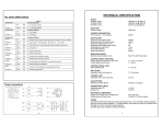
Fig5. Engineer Programming Flow Chart
MENU
No
1
System is Unset
Enter Engineer Code
Press 0 (Quit)
Press
Do you wish to use
Engineer Mode
NO
Press YES
Press NO
Press 0 (Quit)
This is Engineer Mode
Enter Option Number Then YES
Press NO
This is the
Existing Setting
FUNCTION
OPTIONS AVAILABLE
Zone1 Attributes LEFT DIGIT
0=12Hr
1=E/E
2=Access
3=Panic
4=24Hr
5=Fire
6=Alert
7=Exit Term
8=Part E/E
RIGHT DIGIT
0=Full Set
1=Part1
2=Part2
3=Part1&2
4=Full Set+Chime
5=Part1+Chime
6=Part2+Chime
7=Part 1&2+Chime
Zone 2 Attributes
As Zone1 Options
80
3
Zone 3 Attributes
As Zone1 Options
00
4
Zone 4 Attributes
As Zone1 Options
01
5
Zone 5 Attributes
As Zone1 Options
02
6
Zone 6 Attributes
As Zone1 Options
00
7
Zone 7 Attributes
As Zone 1 Options
00
8
Sounder Level
CHIME
LEFT DIGIT
ENTRY/EXIT
RIGHT DIGIT
0-9
Press NO
Enter new
Setting Here
55
00 - 99seconds
30
10
Part Set Exit Time
00 - 99seconds
30
Setting Modes
FULL SET
LEFT DIGIT
PART SET
RIGHT DIGIT
0=Exit Term
1=E/E Door
2=Time
3=Time+E/E
0=Exit Term
1=E/E Door
2=Time
3=Time+E/E
This section will give a description of the programmable options that are available on
the GARDTEC 370 Control Panel. For more details of the parameters available for
each option please refer to the section Programming Charts.
Zone 1-7 Attributes (Option No.1-7)
This option allows the zone type, zone part set remove and zone chime features to
be programmed for zone 1-7.
Sounder Level (Option No.8)
This option allows for the fine adjustment of the speaker volume for Entry/Exit tone
and Chime to be programmed. Coarse adjustment is via the potentiometer situated to
the edge of the PCB.
Full Set Exit Time (Option No.9)
Allows the Exit Time for full set to be programmed.
00 - 99seconds
30
14
Entry Time 2
00 - 99seconds
10
15
Keypad
16
Bell Re-Arms
00 Re-Arms - 99 Re-Arms
99
17
Bell Ring Time
00 minutes - 99 minutes
20
18
Not Used
Always 00
00
19
Bell Mode
20
Not Used
21
Reset Modes
BELL TYPE
LEFT DIGIT
0=SAB
1=SCB
TAMPER RING
RIGHT DIGIT
0=Off
1=On
Always 00
LEFT DIGIT
Always 0
Service Timer
00weeks - 98weeks.
00
RESET MODE
RIGHT DIGIT
0=Any Code
1=Master Code
2=Anti-Code
3=Engineer Code
01
99 = Off
99
Display Messages (Log)
Apart from the System and Status displays the following messages may also appear
whilst viewing the Log.
'
System Part 1 Set
'S
'
System Part 2 Set
'S
'
System Part 3 Set
' o1 '
Unset User 1
' o2 '
Unset User 2
Service Timer (Option No.22)
The service timer period is programmed using this function. When service time
expires the system will lock the user out. Extra service may be gained using the
Anti-Code software. If the timer is set to 99 weeks the timer function is Off.
' o3 '
Unset User 3
' o4 '
Unset User 4
' o5 '
Unset User 5
' o6 '
Unset User 6
' o7 '
Unset User 7
' o8 '
Unset User 8
Display Messages
' o9 '
Unset User 9
' o0 '
Unset User 0 (Engineer)
Alarm has occurred
' rE '
Watchdog reset
Reset Modes (Option No.21)
The reset modes are programmed using this function.
'E
't'
Tamper zone
'CA'
' AL '
'
System Full Setting
Alert keys activated
'E
'
System Part 1 Setting
'E
'E
'
System Part 3 Setting
Un'
'
'
System Fully Set
'
'
System Part 1 Set
'
'
System Part 2 Set
'
'
System Part 3 Set
'AL '
An Alarm has occurred
'Ac'
Anti-Code reset required
Keypad (Option No.15)
Key numbers 1 & 3 when pressed together may be programmed using this function to
give a particular response.
'Fb'
Fuse Fail or Battery Fault
'Ct'
RKP Tamper
'bb'
Bell box Tamper
'Pc'
Mains Power Cut
Bell Re-Arms (Option No.16)
This option is used to program the number of times the Bell will Re-Arm during a set
period.
'Cb'
Control Box Tamper
'En'
Engineer Reset required (or Service Timer activated).
Bell Ring Time (Option No.17)
This option is used to program the Bell ring time.
Page 13
'
Four reset modes are available after an alarm. These are as follows.
Any Code
The system will reset the next time Any Code is used to set the system.
Master Code
The system will only reset if the Master Code or Engineer code is used to set the
system.
Engineer Code
The system will only reset if the Engineer Code is used to set the system.
Anti-Code
The system may only be reset by use of an Anti-Code.
The engineer code may be used to override the Anti-Code Reset.
To Reset System:1)
Enter Code of correct type (see above).
2)
Proceed to set the system.
3)
If a set is not required re-enter the code to abort setting.
To Reset by Anti-Code:1)
Make a note of the Code given by the display.
2)
Using the Gardiner Technology Anti-Code software on a P.C or an
Anti-Code Generator enter the four digit source code given by the Panel.
3)
Enter the resulting four digit Anti-Code into the Control Panel.
Zone Type Terminology
System Part 2 Setting
System is Unset
' 1 to 7 ' (flashing)
12 Hour
Zone active when Control Panel is Set
Access
Will allow to pass through on Exit.
Will allow to pass through on entry only if entry/exit is opened first
24 Hour
Internal sounder if Unset. Full alarm if Set.
Entry/Exit
Zone used as last exit point or first entry point.
Part E/E
As Access if Control Panel is Full Set
As entry/exit if Control Panel is Part Set
P.A
24 Hour Personal Attack. Active if Control Panel is Set or Unset
Alert
Internal sounder only. Recorded to Log
Fire
Will give Fire alarm when activated (pulsed external sounders) with
panel set or unset.
Exit Terminator With Panel programmed to set with exit terminator the panel
will only set when zone is activated during exit.
Page 11
Other Accessories
'S
Represent zones 1 to 7
Resetting After an Alarm
00
System Full Set
'1 to 7'
Page 12
10
RIGHT DIGIT
Always 0
'
Setting Modes (Option No.11)
Allows the setting modes for Full and Part-set to be programmed.
Entry Time 2 (Option No.14)
Allows Entry Time 2 to be programmed.
ALERT KEYS 1&3
LEFT DIGIT
0=Off
1=Panic
2=Fire
3=Alert
'S
The Following System messages are possible.
Entry Time 1 (Option No.13)
Entry time may be looked at as three events. Entry time 1 will give the normal Entry
tone. Entry time 2 will give a louder warning tone. After both times have expired the
external sounders will sound. This option allows Entry Time 1 to be programmed.
31
Page 10
Bell Mode (Option No.19)
The Bell Mode Function allows the mode of the Bell to be programmed from SAB to
SCB. In SAB mode the current for the sounder is supplied from the Control Panel
unless the cable to the Bell box is cut. In SCB mode the current for the sounder is
supplied by the sounder battery under all circumstances. The Bell Tamper mode if
programmed ON will always trigger the external sounder from the control panel in the
event of a Bell Tamper.
Part Set Exit Time (Option No.10)
Allows the Exit Time for part set to be programmed.
Part-set Sounders & Output 1 Mode (Option No.12)
Allows the Part-set exit sounder mode and the operating mode of the programmable
output 1 terminal to be programmed.
PROGRAMMABLE
OUTPUT1 PGM1
RIGHT DIGIT
0=Pulse On
1=SW+
2=Pulse Off
3=Bell
4=Strobe
5=Entry/Exit
6=Test
7=Int. Alarm
Entry Time 1
Page 9
Page 8
DEFAULT
13
22
Programmable Options Description
Part Set Sounders PART
& Output 1 Mode SOUNDERS
LEFT DIGIT
0=All Parts silent
1=Part 2 silent
2=Parts1&3 silent
3=All Parts
Audible
22
Enter New Value Then Press YES
Press YES
Enter new Engineer Code
Press YES
Re-Enter Engineer Code
Press YES
Press 0 to return to Unset
OPTIONS AVAILABLE
0-9
Full Set Exit Time
11
FUNCTION
The terminology used for the various zone types are explained in this section.
9
Press NO
MENU
No
12
14
2
Press NO
Press NO
DEFAULT
Zone 1 to 7 was removed when system was set.
A complete range of accessories are available to compliment your Gardtec 370
security system. Some of this range is shown below:-
Gardtec 370 Speaker Kit (01-087)
A 32 Ohm speaker that clips into the Control Panel.
Rear Tamper (02-064)
The Gardtec Speech Dialler (04-069)
The Gardtec Speech Dialler offers communications between your security system
and any telephone or selected pagers.
One Common message along with three Information messages may be programmed
to be sent to up to four telephone numbers. The unit offers a full range of programmable features to ensure your message gets across.
Gardtec 370 Specification
Power Input
Max Loop Resistance
Loop Delay Time
Fuses
Mains
Aux
Low Voltage Output
Power Supply Rating
Battery Sizes
Construction
Complies with
Number of Zones
Display Type
User Code Default
Engineer Code Default
Event Log Size
No. of User Codes
No. of Part Sets
240V a.c +/- 10% @50Hz
2K Ohm
300 milliseconds
200mA Anti Surge
1A Quick Blow
13.8V (typical) Regulated
1A
12V 1.2A, 12V 2.0A
3mm Polycarbonate
B.S 4737
7 + Tamper
2 x 7 segment LED
5678
1234
80
9
3
Page 14
Additional RKPs
Gardtec 370 LED RKP (01-144)
ACE RX & 2TX Kit (01-141)
ACE RX (01-136)
ACE TX (Key Fob) (01-130)
Up to four RKPs may be fitted to the Gardtec 370 Control Panel.
ACE offers Setting, Unsetting, Part Setting & Resetting via high security Infra-Red
keyfobs. ACE is available as compact stand alone units which are fully compatible
with the Gardtec 370 Control Panel.
Page 15