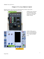
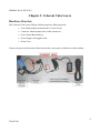
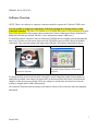
1
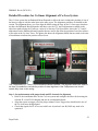
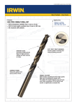
DM00001 Rev A (DCN 031)
Co-Lase Users Guide
These instructions are protected by copyright. All rights reserved.
Propel Labs, Inc.
http://www.propel-labs.com
131 East Lincoln Avenue, Suite 200
Fort Collins, CO 80524
1
Propel Labs
DM00001 Rev A (DCN 031)
Table of Contents
Chapter 1: Introduction ......................................................................................................................... 3
Safety Information ....................................................................................................................... 4
Chapter 2: Co-Lase Shutter Control ...................................................................................................... 5
Chapter 3: Coherent Cube Lasers .......................................................................................................... 6
Chapter 4: Coherent Sapphire LP Lasers ............................................................................................... 9
Chapter 5: Coherent Genesis MX Laser .............................................................................................. 11
Chapter 6: Coherent Genesis CX Laser ............................................................................................... 13
Chapter 7: Cobolt Laser ...................................................................................................................... 15
Chapter 8: MPB Communications Laser ............................................................................................. 17
Chapter 9: XYZ Fine Alignment ......................................................................................................... 20
Chapter 10: Maintenance..................................................................................................................... 24
2
Propel Labs
DM00001 Rev A (DCN 031)
Chapter 1: Introduction
The Co-Lase tower is a laser upgrade to MoFlo* Legacy and MoFlo XDP cell sorters. This user’s
guide covers the basic operation of the various lasers and fine alignment to be done as needed. Any
additional troubleshooting or adjustments not covered in this users guide should only be done by
trained field service personnel.
The Co-Lase systems are built with a variety of lasers. The following chapters describe the specific
hardware and software installations needed for each of the Propel Labs supplied standard lasers used in
the Co-Lase system. The lasers covered in this guide include:
• Coherent CUBE (405nm, 640nm)
• Coherent Sapphire LP (488nm, 561nm, 594nm)
• Coherent Genesis MX (460nm)
• Coherent Genesis CX (355nm)
• Cobolt (594nm)
• MPB Communications (592nm)
Customer supplied lasers should be operated in accordance with the individual manufactures
recommendations.
*MoFlo is a registered trademark of Beckman Coulter, Inc.
3
Propel Labs
DM00001 Rev A (DCN 031)
Safety Information
Please review the safety information shown below before operating the Co-Lase tower.
This symbol draws attention to a possible danger to life or injury
if the associated directions are not followed correctly. Only
qualified, trained technicians should carry out service work on
electronic components due to potential shock hazard.
Electronic components are sensitive to electrostatic charges and
can be destroyed by a discharge. Use caution when working
around the system.
Caution should be used when adjusting alignment of the laser
beams. Direct laser light could cause permanent injury. Use
safety precautions when working with open beams.
4
Propel Labs
DM00001 Rev A (DCN 031)
Chapter 2: Co-Lase Shutter Control
Each laser in the Co-Lase Tower has an individual shutter control as shown below.
NOTE: There is no Master Shutter for the Co-Lase.
A MoFlo Legacy system has
the individual laser shutter
controls on a control board
attached to the top of the
Pressure Console.
A MoFlo XDP system has
access to the individual laser
shutter controls through the
“Laser Control by Pinhole”
screen.
5
Propel Labs
DM00001 Rev A (DCN 031)
Chapter 3: Coherent Cube Lasers
Hardware Overview
The Coherent Cube Lasers (405nm, 640nm) require the following items:
•
Laser Head (usually mounted in the Co-Lase Tower)
•
Connector which separates into 4 cable connectors
•
Laser Control Box and Keys
•
Power Supply with toggle switch
•
Power Cord
Connect the power and electrical cables between the correct pieces of the laser as shown below.
6
Propel Labs
DM00001 Rev A (DCN 031)
Software Overview
NOTE: There is no software or computer connection needed to operate the Coherent CUBE Lasers.
It is only possible to change the output power of the laser through the Coherent software called
Coherent Connection. This software is available on a CD-ROM and requires a USB connection to be made
between the laser head and the computer that is running the Coherent Connection software. (Both the CDROM and USB cable are included with the Co-Lase systems that contain CUBE lasers.)
To install the software, insert the Coherent Connection CD-ROM into the computer it should automatically
start to run. If it does not, click on the setup.exe on the CD-ROM to get it to install. Choose the defaults,
when asked. Then, open the software and connect the USB cable. The software should look as shown.
The CD-ROM containing Coherent
Connection software.
Screenshot from Coherent Connection
software.
To change the laser power is read out at the center dial. It can be changed by typing in a new number or
sliding the bar marked Laser Output. Then press SET (on the bottom left of the screen). The dial should
change to reflect the new power setting. These new settings are stored in the laser head even when the
software is stopped and the USB is disconnected.
The Coherent Connection software also gives the number of hours of use on the laser and some diagnostic
information.
7
Propel Labs
DM00001 Rev A (DCN 031)
Power On/Off
•
Plug in the power.
•
Turn the key to the ON position.
•
Toggle the switch to the ON position. The laser should turn on immediately.
•
TO TURN OFF: Toggle the switch to the OFF position and/or turn Key from ON to
STANDBY position.
Troubleshooting
NOTE: There is no software or computer connection needed to operate the Coherent CUBE Lasers.
Please contact a trained service engineer for troubleshooting assistance.
8
Propel Labs
DM00001 Rev A (DCN 031)
Chapter 4: Coherent Sapphire LP Lasers
Hardware Overview
The Coherent Sapphire LP Lasers (488nm, 532nm, 561nm) require the following items:
•
Laser Head (usually mounted in the Co-Lase Tower)
•
Laser Control Box and Keys
•
Cable to connect Control Box to Laser Head
•
Power Cord
Connect the power and electrical cables between the correct pieces of the laser as shown below.
9
Propel Labs
DM00001 Rev A (DCN 031)
Software Overview
NOTE: There is no software or computer connection needed to operate the Coherent Sapphire LP
Lasers.
Power On/Off
•
If the front display is not on, switch the power ON at the back of the Control Box ( near
the AC Power Plug)
•
Wait until the Display says that the Warm-up has completed
•
Turn Key from STANDBY to ON position
•
Look at Display. There are two lines indicating the laser power. You control the SET
power by turning the POWER knob on the front of the Control Box.
•
PRESS the POWER knob when you want the laser power to change to the new SET
power.
•
TO TURN OFF: Turn Key from ON to STANDBY position.
Troubleshooting
Please consult the Coherent Manuals for any additional support.
Please contact a trained service engineer for troubleshooting assistance.
10
Propel Labs
DM00001 Rev A (DCN 031)
Chapter 5: Coherent Genesis MX Laser
Hardware Overview
The Coherent Genesis Laser (460nm) requires the following items:
•
Laser Head (usually mounted in the Co-Lase Tower)
•
Laser Control Box and Keys
•
Cable to connect Control Box to Laser Head
•
Power Cord
Connect the power and electrical cables between the correct pieces of the laser as shown below.
11
Propel Labs
DM00001 Rev A (DCN 031)
Software Overview
NOTE: There is no software or computer connection needed to operate the Coherent Genesis MX
Laser.
Power On/Off
•
Do not plug in the AC Power Plug until you have connected all of the cables as shown.
Tighten the screws to hold the cable at both ends.
•
If the front display is not on, switch the power ON at the back of the Control Box (near
the AC Power Plug)
•
While the system is coming up, the Interlock OK and System Fault LED may blink until
the system is ready to lase. The system is ready to use with the System Fault LED is off
and the Interlock OK LED is on (and not blinking).
•
Turn Key from STANDBY to ON position
•
The front display will read the laser power.
•
To adjust the power, turn the knob on the control unit. If you press the knob in while
turning, the adjustment is coarse. If you simply turn the knob, then it is the fine POWER
adjustment.
•
DO NOT EXCEED 300mWatts of OUTPUT POWER.
•
TO TURN OFF: Turn Key from ON to STANDBY position. Switch the power off at
the Control Box.
Troubleshooting
Please consult the Coherent Manuals for any additional support.
Please contact a trained service engineer for troubleshooting assistance.
12
Propel Labs
DM00001 Rev A (DCN 031)
Chapter 6: Coherent Genesis CX Laser
Hardware Overview
The Coherent Genesis CX Lasers require the following items:
•
Laser Head (usually mounted in the Co-Lase Tower)
•
Laser Control Box and Keys
•
2 Cables to connect Control Box to Laser Head (1 for power 1 for control)
•
Power Cord
NOTE: The Genesis CX laser requires a safety plug to be installed whenever it is disconnected from the
power supply. This plug is show in below and should be connected to the power cable for storage.
Do not plug in the AC Power Plug until you have connected all of the cables.
Connect the heavy power and control cables between the laser head and power box as shown. Tighten the
screws to hold the cable at both ends. Be sure the 4 terminal connections are made at the 2 ends of the power
cable. Connect the AC power plug to the wall.
13
Propel Labs
DM00001 Rev A (DCN 031)
Software Overview
NOTE: There is no software or computer connection needed to operate the Coherent Genesis CX Laser.
Power On/Off
•
If the front display is not on, switch the power ON at the back of the Control Box (near the AC
Power Plug)
•
While the system is coming up, the Interlock OK and System Fault LED may blink until the
system is ready to lase. The system is ready to use with the System Fault LED is off and the
Interlock OK LED is on (and not blinking).
•
Turn Key from STANDBY to ON position
•
The front display will read the laser power and will always start up at 0 mWatts.
•
To adjust the power, turn the knob on the control unit. If you press the knob in while turning,
the adjustment is coarse. If you simply turn the knob, then it is the fine POWER adjustment.
•
TO TURN OFF: Turn Key from ON to STANDBY position. Switch the power off at the
Control Box.
Troubleshooting
Please consult the Coherent Manuals for any additional support.
Please contact a trained service engineer for troubleshooting assistance.
14
Propel Labs
DM00001 Rev A (DCN 031)
Chapter 7: Cobolt Laser
Hardware Overview
The Cobolt Laser (594nm) requires the following items:
•
Laser Head (usually mounted in the Co-Lase Tower)
•
Laser Control Box and Keys
•
Cable to connect Control Box to Laser Head
•
Power Cord
Connect the Power and electrical cables between the correct pieces of the laser as shown below.
15
Propel Labs
DM00001 Rev A (DCN 031)
Software Overview
NOTE: There is no software or computer connection needed to operate the Cobolt Laser.
Power On/Off
•
Do not plug in the AC Power Plug until you have connected all of the cables as shown.
Tighten the screws to hold the cable at both ends.
•
Plug in the AC Power into an outlet.
•
The Laser now goes through the following start-up sequence.
• Temperature Stabilization (1-2 minutes) during which the POW LED is flashing,
• Once the POW LED is lit continuously, Turn Key from OFF to ON position.
• The laser will start emitting light and the ON LED will be lit.
• Once the laser has reached the pre-set laser power, the LOCK LED will be lit.
•
TO TURN OFF: Turn Key from ON to OFF position.
Troubleshooting
Please consult the Cobolt Manuals for any additional support.
Please contact a trained service engineer for troubleshooting assistance.
16
Propel Labs
DM00001 Rev A (DCN 031)
Chapter 8: MPB Communications Laser
Hardware Overview
The MPB Communications Laser (592nm) requires the following items:
•
Laser Head with a permanent armored optical fiber connection to the Control Box.
•
Blue Electrical Cable to connect Control Box to Laser Head
•
Power Cord
•
USB Cable to Connect to PC
•
CD-ROM
Connect the Power and electrical cables between the correct pieces of the laser as shown.
17
Propel Labs
DM00001 Rev A (DCN 031)
Software Overview
•
Put the MPB Communications CD-ROM into the PC that will be used to turn this laser
ON/OFF
•
Create a folder called MPB Laser and copy the items from the CD-ROM into this folder.
•
Make a shortcut for the application “GUI-VFLver2.3.exe” and put it on the desktop.
•
Turn on Power to the Control Box.
•
Plug in the USB cable from the Control Box to the PC.
•
Let the USB Driver install from the CD-ROM (“MPB USB CDC”). Click “Continue
Anyway” if you receive a question about the hardware not passing a logo test.
•
Start the application “GUI-VFLver2.3.exe” and be sure that it does not say “No Laser”
at the bottom. If it cannot find the laser, try another USB port on the PC and let the
drivers install again.
•
Once the software has been installed and has control of the laser, take out the CD-ROM
and store it in a safe place.
Power On/Off
•
Turn on Power to the Control Box
•
You should see the Green LED for the SHG on Control Box.
• Start the application “GUI-VFLver2.3.exe” and you should see the application as
shown
18
Propel Labs
DM00001 Rev A (DCN 031)
•
Click the button next to “Power, mW” to run the laser Power Stabilization Mode
•
Use the Up/Down Arrows to set the output power in mWatts
•
Click ON button (bottom left) and then Activate button (top right).
•
In the Power Stabilization Mode, the unit works with a constant output power, which is
realized with an active power stabilization feedback loop. The Manufacturer
recommends turning the unit on initially at a relatively low output power, for
example at 50 mW, then gradually increasing the output power to the operating
level by changing the Set Point and clicking Activate.
•
TO TURN THE LASER OFF – click OFF button on the lower left on the software.
Troubleshooting
Please consult the MPB Communication Manuals on the CD-ROM for any additional support.
Please contact a trained service engineer for troubleshooting assistance.
19
Propel Labs
DM00001 Rev A (DCN 031)
Chapter 9: XYZ Fine Alignment
The Co-Lase tower is equipped with a beam expander adjustment to compensate for variation in laser
beam focus. Please take caution when making these adjustments as stray laser light will be accessible.
It is suggested that this form be used to track alignment during this process. This chapter gives the
alignment procedure for a practiced user (Quick Procedure) and a new user (Detailed Procedure).
LASER A: Path without Enhanced Beam Expander
Wavelength ________nm
Power __________ mW
FL-A ______________
LASER B: Path with Enhanced Beam Expander
Wavelength ________nm Power __________ mW
Recommended Alignment Bead _________________
Drawing of filter layout for light to reach FL_A and FL_B:
FL-B ______________
Results Achieved
Date __________
Trigger ___________
Fluorescence Signal: FL-A
________ PMT Voltage
________ Median
________ CV
Fluorescence Signal: FL-B
________ PMT Voltage
________ Median
________ CV
20
Propel Labs
DM00001 Rev A (DCN 031)
Quick Procedure for Co-linear Alignment of Co-Lase System
This procedure gives the basics for alignment and should be used as an alignment guide once the
detailed procedure is fully understood.
Step 1: Set up filters for detecting the selected FL-A and FL-B channels and put on
recommended beads. Align the system to trigger off of the channel indicated above.
Step 2: Open the shutter for Laser A and close the shutter for Laser B. Adjust the BSO for
maximum signal on the FL-A channel. If the signals reached are different from the ones
written above, it may indicate a different problem than Co-Lase Alignment (i.e. stream
alignment or issues, etc.)
Step 3: DO NOT MOVE THE BSO. Close the shutter for Laser A, then open the shutter for
Laser B and set the display to look at the FL-B signal. Look to see if there is a diffraction ring
in the interrogation chamber. Using only the X-Y adjustment knobs on the enhanced beam
expander in the Co-Lase system, first establish a diffraction ring and then peak up the FL-B
signal. These X-Y knobs should only need very small adjustments to peak the signal.
Step 4: The Z-adjustment knob of the enhanced beam expander can be optimized as well. This
is achieved by very small rotation of the barrel while still watching the FL-B signal. If zadjustment is required, optimal results are often achieved by iterating between z-adjustments
and x-y adjustments. To accomplish this, alternate between steps 3 and 4 until the best results
are achieved.
Step 5: The system should now be co-linear with best signals occurring with the BSO at the
same position for both lasers. If this is not the case, go back and repeat Steps 2-4.
21
Propel Labs
DM00001 Rev A (DCN 031)
Detailed Procedure for Co-linear Alignment of Co-Lase System
The Co-Lase system has an Enhanced Beam Expander to allow the user to adjust the position of one of
the lasers to align it with the other laser in the same tower. The alignment procedure is detailed in this
section. The alignment theory is to first align the MoFlo using the laser in the Co-Lase tower that does
not have the Enhanced Beam Expander and then to use the X, Y and Z adjustments available in the
other laser path to bring the 2 lasers to a state of co-linearity. The figure below shows the X, Y and Z
adjustments on the Enhanced beam Expander that are used to fine tune the position of one laser relative
to the other in the Co-Lase Tower. The photo also shows the Alignment Marks that are made at the time
of installation to indicate the position of best focus.
The 3 adjustments (X, Y and Z) on the Enhanced Beam Expander. The Alignment Marks are made at
the time of installation to indicate the position for best alignment of the Z-adjustment and should
remain fairly close to this setting.
Step 1: Set up instrument with proper beads and FL channels for alignment
• Refer to the installation sheet for the Co-Lase system and configure the filters for detecting the
selected FL-A and FL-B channels and put on recommended beads.
• Align the system to trigger off of the proper channel. Note: Trigger laser should not be one of
the Co-Lase lasers being aligned.
• Check that signals for FL-A are seen with Laser A (and not Laser B). BSO may need to be
optimized.
22
Propel Labs
DM00001 Rev A (DCN 031)
•
•
Check that signals for FL-B are seen with Laser B (and not Laser A). BSO may need to be
optimized.
If the signals are different from the ones expected, it may indicate a different problem than CoLase Alignment (i.e. stream alignment or issues, etc.) and should be addressed before
proceeding.
Step 2: Optimize BSO for Laser A
• Open the shutter for Laser A and close the shutter for Laser B.
• Adjust the BSO for maximum signal on the FL-A channel. If possible, keep track of the change
in the BSO position between lasers A and B as to whether the shift is mostly Horizontal,
Vertical or in the Focus direction.
Step 3: Optimize Enhanced Beam Expander for Laser B in X & Y
• DO NOT MOVE THE BSO.
• Close the shutter for Laser A, then open the shutter for Laser B and set the display to look at the
FL-B signal.
• Look to see if there is a diffraction ring in the interrogation chamber. Using only the X-Y
adjustment knobs on the enhanced beam expander in the Co-Lase system, first establish a
diffraction ring and then peak up the FL-B signal. These X-Y knobs should only need very
small adjustments to peak the signal.
NOTE: If the change in BSO position required for best signals on the Laser A vs. Laser B was
dominated by vertical shift, then start with the vertical knob of the Enhanced Beam Expander. And
similarly, if the BSO shift was mostly in the horizontal, start with the horizontal adjustment on the
Enhanced Beam Expander.
Step 4: Optimize Enhanced Beam Expander for Laser B in Z (focus)
• The Z-adjustment knob of the enhanced beam expander can be optimized as well. Similar to the
BSO adjustment for focus, this adjustment is not as sensitive as the X and Y adjustments.
• The Z-adjustment of the Enhanced Beam Expander is achieved by very small rotation of the
barrel while still watching the FL-B signal.
• If Z-adjustment is required, optimal results are often achieved by iterating between Zadjustments and X-Y adjustments. To accomplish this, alternate between steps 3 and 4 until the
best results are achieved.
• NOTE: Each Enhanced Beam Expander is marked with a pair of alignment mark where the best
location was found for focus during installation. The new position should be very close to that
original alignment location and if finding the optimum position is proving difficult, start with
the barrel aligned with these marks.
Step 5: Check for Co-Linear
•
The system should now be co-linear with best signals occurring on FL-A (with Laser A on) and
FL-B (with Laser B on) with the BSO not needing any adjustment. If this is not the case, go
back and repeat Steps 2-4.
23
Propel Labs
DM00001 Rev A (DCN 031)
Chapter 10: Maintenance
Maintenance of the Co-Lase tower should only be done by qualified, trained field service personnel. If
the need arises to remove or reposition the tower, please contact service personnel to arrange for
relocation.
24
Propel Labs