1
ezLCD-002
2.3
Hardware & Interfaces
2.3.1
Block Diagram
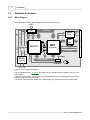
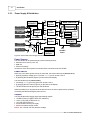
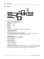
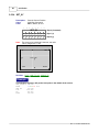
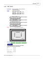
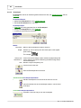
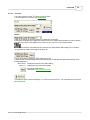
The ezLCD-002 Hardware Block Diagram is shown in Figure 4. below.
LCD
16mA
LCD_ON
8 Bit Data
RS232
Driver
Video
Control
V2
V1
+3.6 - 3.8 V
USB
Client
WAIT
SED1375
RD
WE0
MPU
I2C
ATmega128L
SPI
+3V
WE1
DC/DC
Converter
Vcc
29.4912MHz
LED
22 Pin
ZIF Connector
USB
8 bit Parallel
A0
17 Bit Address
RS232
I/O Connectors
4
7.3728MHz
fck/4
29.4912MHz
3.6 - 7V
Figure 4. ezLCD-002 Block Diagram
The ezLCD-002 receives commands through any of the available interfaces (RS232, USB, I2C, SPI
and Parallel).
The MPU (ATmega128L) processes the received data and writes the resulting pixels into the Video
RAM of the SED1375 LCD controller.
The SED1375 generates the "Digital CRT" video signals, using the data stored in the Video RAM.
Rev. 2.1 © 2007 EarthLCD.com