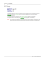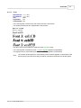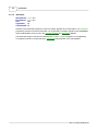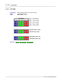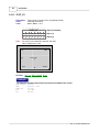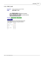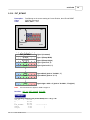
1
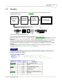
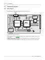
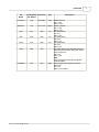
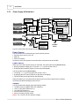
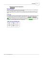
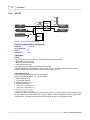
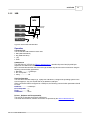
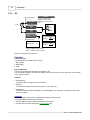
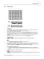
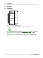
Quick Start
1
1
Quick Start
Install USB Drivers
· Run CP2101_Drivers.exe which is located in the Drivers\USB directory of the ezLCD CD.
· Connect ezLCD to your computer through the USB cable
· Proceed with Plug-and-Play installation
The ezLCD COM port assignment
· Connect ezLCD to your computer through the USB cable
· The ezLCD COM port assignment should be shown in th Device Manager as:
CP2101 USB to UART Bridge Controller (COMx)
where x is the COM port number
Power ON/OFF buttons of the ezLCD-002
· The ezLCD-002 power can be turned ON by pressing the ON pushbutton on the back
· The ezLCD-002 power can be turned OFF by pressing the OFF pushbutton on the back
· The ezLCD power options are describet in the chapter: Power Supply & Distribution
Touch Screen
· Make sure that the USB drivers are installed
· Connect ezLCD to your computer through the USB cable
· Verify the ezLCD COM port assignment
· Power ON the ezLCD
· Make sure that the ezLCD COM port is not opened by other applications
· Run ezLCDtch.exe, which is located in the Utilities\ezLCDtch directory of the ezLCD CD.
· Select the COM port assigned to the ezLCD
· Press the Open button
· The ezLCD touch screen taps should now be reflected by the ezLCDtch utility
Example of sending commands to the ezLCD using a Windows Command Prompt
· Make sure that the USB drivers are installed
· Connect ezLCD to your computer through the USB cable
· Verify the ezLCD COM port assignment. Let's assume that ezLCD is assign to the COM5
· Power ON the ezLCD
· Make sure that the ezLCD COM port is not opened by other applications
· Open Command Prompt on your computer
· Set ezLCD Com port parameters. Type:
MODE COM5 BAUD=115200 PARITY=N DATA=8 STOP=1
· Turn the ezLCD Light ON. Type:
ECHO "" > COM5
· Set current ezLCD color to green. Type:
ECHO $8 > COM5
· Send CLS command Type:
ECHO ! > COM5
The ezLCD will fill it's entire screen with the green color
· Turn the ezLCD Light OFF. Type:
ECHO # > COM5
· etc.
Rev. 2.1 © 2007 EarthLCD.com
2
ezLCD-002
2
ezLCD-002
2.1
Overview
Congratulations on your purchase of ezLCD-002!
The ezLCD-002 is an all-in-one advanced color TFT LCD panel which includes:
· 240x160 pixel, 512 color, 2.7" TFT LCD (Sony ACX705AKM)
· LCD controller (Epson SED1375)
· Embedded processor (Atmel ATmega128L)
· Power supply, which generates all the voltages needed by the logic and the display itself
· Lithium-Ion battery charger
· Touch screen
· Interface drivers and other circuitry
The ezLCD-002 communicates with the outside world through several implemented interfaces:
· RS232
· USB
· I2C
· SPI
· 8 bit parallel (Centronix printer protocol)
The ezLCD-002 is driven by a set of commands, which can be fed through any of the implemented
interfaces. The device may be used as an "intelligent" display, or as a stand alone device. There is
plenty of flash memory left in ATmega128 to incorporate additional graphical instructions, or to
customize the software for particular tasks. Possible applications include automotive, avionics,
nautical, industrial control, hobby, etc.
Note:
This is a preliminary documentation.
Rev. 2.1 © 2007 EarthLCD.com
ezLCD-002
2.2
3
Operation
The ezLCD-002 is driven by a set of 8 bit commands, which can be received by any of the
implemented interfaces.
LCD
Controller
Vcc
128 MB
Command
Interpreter
Command
Buffer
RS232
USB
I2C
LCD Display
MMC
SPI
8 bit Parallel
Figure 3. ezLCD-002 Data flow Diagram
Each of the implemented interfaces uses the same set of ezLCD Commands.
Upon arrival, the ezLCD Commands are stored into the 1024 byte long Command Buffer as shown in
Figure 3.
All interfaces use the same Command Buffer. The Command Interpreter (Figure 3.), picks up byteby-byte the commands stored in the Command Buffer and drives the LCD Controller with the
corresponding set of signals and instructions. The commands are processed on a First-In, First-Out
principle.
This data flow architecture makes possible the implementation of some advanced graphical
commands, like CIRCLE_R, LINE_TO_XY, PUT_BITMAP, etc.
Example:
The following commands will draw a green circle with a radius of 60 pixels, and a centered
position at column 120, row 80.
Pseudo-Code (ANSI C format):
SetColor(GREEN); /* Set the drawing color to green */
SetXY(120, 80);
/* Set the position to x = 120, y = 80 */
CircleR(60);
/* Draw the circle with the radius of 60 pixels */
Data sent to the ezLCD (Columns: Value and Format):
Mnemonic
Value
Format
Comment
SET_COLOR
24 hex
Set the drawing color to:
green
00111000 bin
SET_XY
120
25 hex
120 dec
80
80 dec
CIRCLE_R
29 hex
60
60 dec
Rev. 2.1 © 2007 EarthLCD.com
green
Set the drawing position to:
x (column) = 120
y (row) = 80
Draw the circle with the radius of:
60 pixels
ezLCD-002
2.3
Hardware & Interfaces
2.3.1
Block Diagram
The ezLCD-002 Hardware Block Diagram is shown in Figure 4. below.
LCD
16mA
LCD_ON
8 Bit Data
RS232
Driver
Video
Control
V2
V1
+3.6 - 3.8 V
USB
Client
WAIT
SED1375
RD
WE0
MPU
I2C
ATmega128L
SPI
+3V
WE1
DC/DC
Converter
Vcc
29.4912MHz
LED
22 Pin
ZIF Connector
USB
8 bit Parallel
A0
17 Bit Address
RS232
I/O Connectors
4
7.3728MHz
fck/4
29.4912MHz
3.6 - 7V
Figure 4. ezLCD-002 Block Diagram
The ezLCD-002 receives commands through any of the available interfaces (RS232, USB, I2C, SPI
and Parallel).
The MPU (ATmega128L) processes the received data and writes the resulting pixels into the Video
RAM of the SED1375 LCD controller.
The SED1375 generates the "Digital CRT" video signals, using the data stored in the Video RAM.
Rev. 2.1 © 2007 EarthLCD.com
ezLCD-002
Pin Configuration
CN2
N/C
N/C
GND
D6
D4
D2
D0
GND
RESET#
LTX
E3
STROBE#
ACK#
MOSI
MISO
CN1
1
2
3
4
5
6
7
8
9
10
11
12
13
14
15
16
17
18
19
20
21
22
23
24
25
26
27
28
29
30
31
11
+EXT_PWR
ON/OFF
9
+EXT_PWR
+EXT_PWR
7
PWR
ON/OFF
LIGHT_ON#
5
+3V Ref
RS232TX
GND
3
D7
RS232RX
1
D5
BATT+
+EXT_PWR
D3
D1
BATT
SDA
SCL
ON/OFF
LRX
+EXT_PWR
BATT+
GND
E2
LIGHT_ON#
USB1
E4
RS232TX
BUSY
RS232RX
SS#
BATT+
SCK
+5V
GND
GND
DM
N/C
DP
10
8
6
4
2
IR_ON#
GND
GND
GND
GND
CN3
A
2.3.2
5
1
2
3
4
5
6
7
Figure 5. LCD-002 Connectors
The table below describes the pins and signals of the ezLCD-002.
Since the ezLCD-002 uses the ATmega128 microcontroller by Atmel, the table also shows the
corresponding ATmega128 names for applicable pins.
Pin
Name
+3V Ref
ATmega128 Connector
Pin Names
N/A
CN2
+5V
N/A
+EXT_PWR
N/A
USB1
Type
Description
Output I/O reference voltage. may be used as a
pull-up source (I2C etc.).
It SHOULD NOT be used as a power
source.
Input Pwr. USB VBUS Signal.
CN1,CN2, Input Pwr. External power voltage.
CN3, PWR
Min = +3.6V
Max = +7.0V
ACK#
PE7
CN2
Output Acknowledge signal of the Parallel Interface.
Active low.
Min = 0V
Max = +3V
BATT+
N/A
CN1, CN3, Input Pwr. Lithium-Ion battery +3.6V
BATT
BUSY
PE6
CN2
Output Busy signal of the Parallel Interface.
Active high.
Min = 0V
Max = +3V
This table is continued on the next page
Rev. 2.1 © 2007 EarthLCD.com
6
ezLCD-002
Pin
Name
ATmega128 Connector
Pin Names
Type
Description
D0 -D7
PF0 - PF7
CN2
Input
DM
N/A
USB1
I/O
Data inputs of the Parallel Interface.
Min = 0V
Max = +3V or Open
USB Data Minus
DP
N/A
USB1
I/O
USB Data Plus
E2 - E4
PE2 - PE4
CN2
I/O
Spare
GND
GND
Gnd
Ground
IR_ON#
N/A
CN1, CN2,
CN3, USB,
PWR,
BATT
CN1
LIGHT_ON#
D7
CN1, CN3
LRX
PE0
CN2
LTX
PE1
CN2
MISO
PB3
CN2
MOSI
PB2
CN2
N/C
N/A
CN2, USB1
ON/OFF
N/A
CN1, CN2,
CN3
Input
RESET#
RESET
CN2
Input
Output Drain of the IRLML2502 N-Channel
MOSFET, capable of sinking up to 4A. The
source of the IRLML2502 is connected to
GND. This pin may be used to drive hipower infrared transmitter. The gate of the
IRLML2502 is connected to PB7 pin of the
ATmega128L.
Input Light On signal. Active Lo. When connected
to GND turns on the LCD front light. The
function of this signal is identical to
LIGHT_ON and LIGHT_OFF commands.
Min = Gnd
Max = +3V or Open
Input
RS232 TTL Input
Min = 0V
Max = 3V
Output RS232 TTL Output
Min = 0V
Max = 3V
I/O
SPI Master Input Slave Output signal
Min = 0V
Max = 3V
I/O
SPI Master Output Slave Input signal
Min = 0V
Max = 3V
N/A
Not Connected
+3.6 to +7V turns ON the ezLCD-002 power.
0 to +1V turns OFF the ezLCD-002 power.
Open leaves the ezLCD-002 power
unchanged.
Tmin = 1ms
Rin > 250 kOhm.
Hardware reset. Active low.
Min = 0V
Max = +3V or Open
This table is continued on the next page
Rev. 2.1 © 2007 EarthLCD.com
ezLCD-002
Pin
Name
ATmega128 Connector
Pin Names
RS232RX
N/A
CN1,CN3
RS232TX
N/A
CN1, CN3
SCK
PB1
CN2
SCL
PD0
CN2
SDA
PD1
CN2
SS#
PB0
CN2
STROBE#
PE5
CN2
Rev. 2.1 © 2007 EarthLCD.com
Type
Input
Description
RS232 Receive
Min = -12V
Max = +12V
Output RS232 Transmit
Min = -12V
Max = +12V
I/O
SPI Serial Clock.
Min = 0V
Max = +3V
I/O
I2C Serial Clock
Min = 0V
Max = +3V
I/O
I2C Serial Data
Min = 0V
Max = +3V
I
SPI Slave Select. This signal is used only
when the ezLCD-002 is configures as SPI
Slave. Active low.
Min = 0V
Max = +3V
Note:
During reset and power-up this signal is
used as PGM#.
Input Strobe signal of the Parallel Interface.
Active low.
Min = 0V
Max = +3V or Open
7
2.3.3
ezLCD-002
Power Supply & Distribution
VIN
LCD_ON Signal
from SED1375
VO
VIN
EN
White LED Driver
+3.8V
ON
Regulator GND
16mA
16mA
BATT+
CN1, CN2, CN3, PWR
DC
+EXT_PWR
USB
CN1, CN3, BATT
BAT
VIN
Battery
Charger
+5V
+3V
ON
USB1
Regulator GND
VIN
VO
+3V
100k
ON
Button
ON/OFF
+3.8V LCD
+3V LCD
Inp. Power
ON
LCD Light
VO
GND
10k
+3V Ref
10k
OFF
GND CN1, CN2, CN3,
LCD
Display
LIGHT_ON Signal
from MPU
Regulator GND
CN1, CN2, CN3
Button
CN2
3V3
8
POWER_ON
MPU Output
PWR, BATT, USB1
POWER_SENSE
MPU Input
Vcc
+3V Main
Power
Figure 6. ezLCD-002 Power Supply and Distribution
Power Sources
The ezLCD-002 can be powered by any of the following sources:
· External Power source (3.6 to 7V)
· USB +5V
· Lithium-Ion battery
At least one of the above power sources should be connected to the ezLCD-002.
Power ON/OFF
When any of the above power sources is connected, the ezLCD-002 may be powered on by:
· applying a positive voltage (2V to 7V) to the ON/OFF pin for at least 1 ms or
· by pressing the ON button (Figure 6) on the back of the display
The ezLCD-002 may be powered off by:
· connecting ON/OFF pin to the ground for at least 1 ms or
· by pressing the OFF button (Figure 6) on the back of the display
· The OFF button has the priority over the ON button.
When the ON/OFF/ pin is jumpered to the power source, the ezLCD power will be cycled by
connecting and disconnecting the power source.
Outputs
The ezLCD-002 Power Supply drives the following outputs:
· +3V Main Power Vcc (MPU, SED1375, Interfaces)
· +3.6 to +3.8V LCD (LCD Screen V1)
· +3V LCD (LCD Screen V2)
· 16mA constant current (LCD Light)
· Lithium-Ion battery charge current
NOTE: The +3V Ref is an I/O reference voltage.
Rev. 2.1 © 2007 EarthLCD.com
ezLCD-002
9
It may be used as a pull-up source (I2C etc.).
It SHOULD NOT be used as a power source.
Battery Charging
When the ezLCD-002 is powered by USB only, the charge current is set to 100mA (max). When External
Power is connected, charging current is set at 280mA (typ).
The ezLCD embedded battery charger features a precharge current to protect deeply discharged cells. If
battery voltage is less than 3V, the device enters a precharge mode where charging current is limited to
40mA.
LCD Light
The LCD Light is powered by 16mA generated by the White LED Driver. The LCD Light can be turned
on or off by the LIGHT_ON signal from MPU ( ezLCD commands: LIGHT_ON and LIGHT_OFF ).
Additionally, the light can be turned on by jumping the signal LIGHT_ON# to the GND on the CN1 or
CN3 connector. The Light On condition has priority over Light Off. For example, once LIGHT_ON# is
jumpered to the GND, the light cannot be extinguished by sending the LIGHT_OFF command to the
ezLCD-002. The following table shows the LCD Light logic.
LIGHT_ON LIGHT_ON# LCD Light
OFF
Open
Off
OFF
GND
On
ON
Open
On
ON
GND
On
Rev. 2.1 © 2007 EarthLCD.com
10
2.3.4
ezLCD-002
RS-232
+12V
+3V
RS232
Driver
GND
LRX
GND
-12V
RS232RX
CN2
2.2k
CN1, CN3
LTX
RS232TX
CN2
CN1, CN3
GND CN1, CN2, CN3,
PWR, BATT, USB1
LTX
MPU
Figure 7. ezLCD-002 RS232 Interface
Default Communication Parameters
Baudrate: ............ 115200 bps
No of Stop Bits: .... 1
Parity: .................. Off
Handshake: .......... None
Operation
RS232:
The ezLCD-002 uses 3 wires for a non-handshake RS232 communication:
· RS232 RX (ezLCD receive)
· RS232 TX (ezLCD transmit)
· GND (common ground)
The voltage levels and limits are as per RS232 standard.
The MPU handles the asynchronous communication protocol. The RS232 Driver converts voltage
levels from MPU 0V(Lo) and 3V(Hi) to RS232 -12V(Lo) and +12V(Hi).
Asynchronous Serial:
The ezLCD-002 uses 3 wires for a non-handshake
Asynchronous Serial (RS232-TTL) communication:
· LRX (ezLCD receive)
· LTX (ezLCD transmit)
· GND (common ground)
The voltage levels are:
· 0V to +1V = Lo (logical "0")
· +2V to +3V = Hi (logical "1")
· Absolute minimum: -0.2V
· Absolute maximum: +3.2V
The MPU handles the asynchronous communication protocol. The Asynchronous Serial Interface uses
the same MPU lines as the RS232 does. The 2.2k resistor is used to separate the receive signals from
both interfaces. The Asynchronous Serial receive has the priority over the RS232 receive
Rev. 2.1 © 2007 EarthLCD.com
ezLCD-002
2.3.5
11
USB
MPU
DP
USB1
DM
USB1
Serial Connection
(asynchronous)
USB
Client
+5V
USB1
GND CN1, CN2, CN3,
PWR, BATT, USB1
Figure 8. ezLCD-002 USB Interface
Operation
Connector CN1
The ezLCD-002 USB Interface uses 4 lines:
· DM (USB Data Minus)
· DP (USB Data Plus)
· +5V
· GND
USB Client IC
The USB Client IC (CP2101 by Silicon Laboratories Inc.), handles all protocol and physical layer
aspects of the USB communication.
MPU communicates with the USB Client through standard asynchronous serial connection using the
following communication parameters:
· Baudrate: ............ 115200 bps
· No. of Stop Bits: .... 1
· Parity: .................. Off
Host Configuration
The ezLCD CD includes ready-to-go, royalty free USB drivers, configure the operating system of the
Host Computer to "see" the ezLCD-002 as an additional COM port.
When ezLCD-002 USB is configured as a COM port, the following communication parameters should
be used:
Baudrate: ............ 115200 bps
No. of Stop Bits: .... 1
Parity: .................. Off
Handshake: .......... None
Drivers , Software and Documentation
The ezLCD CD includes the CP2101 USB drivers.
The latest documentation, software and drivers are provided by the Silicon Laboratories Inc.
Rev. 2.1 © 2007 EarthLCD.com
12
2.3.6
ezLCD-002
I2C
Caution!
+3V Ref. is a reference voltage
generated by the ezLCD and it
should not be used as a power
source.
ezLCD
+3V Ref
CN2
2 x Rp
+3V
SCL
2x
40-100k
CN2
MPU
SDA
CN2
GND CN1, CN2, CN3,
When f SCL £100kHz
PWR, BATT, USB1
Max. Rp =
1000
kW
C b+10
When f SCL >100kHz
Min. Rp = 975
W
Max. Rp =
300
kW
C b+10
C b [pF] = capacitance of one bus line
Max C b = 400pF (10 feet, or 3 meters)
Figure 9. ezLCD-002 I2C Interface
Operation
Connector CN2
The ezLCD-002 I2C Interface uses 3 wires:
· SCL (Clock)
· SDA (Data)
· GND
Pull-Up Resistors
The pull-up resistors (Rp) should be connected to +3V.
The ezLCD-002 outputs +3V reference voltage, which may be used as a pull-up source, as it is shown
on the Figure 9. above.
Protocol
· Configuration:
The ezLCD-002 is configured as an I2C Slave.
· Address:
The default I2C address of the ezLCD-002 is 111 dec (6F hex).
· Handshake:
The ezLCD-002 responds with NACK (non-acknowledge) if its' 1024 byte command circular buffer
runs out of space.
Reminder:
I2C address byte consists of the 7 address bits and the R/W bit in LSB.
This means that the address byte should be:
· 222 dec (DE hex) when sending commands to the ezLCD
· 223 dec (DF hex) when reading the Touch Screen data
Rev. 2.1 © 2007 EarthLCD.com
ezLCD-002
2.3.7
13
Touch Screen
0
1
2
3
4
5
6
7
0
$00 $01 $02 $03 $04 $05 $06 $07
1
$10 $11 $12 $13 $14 $15 $16 $17
2
$20 $21 $22 $23 $24 $25 $26 $27
3
$30 $31 $32 $33 $34 $35 $36 $37
4
$40 $41 $42 $43 $44 $45 $46 $47
5
$50 $51 $52 $53 $54 $55 $56 $57
Pen Down
Byte
7
6
5
4
3
2
1
0
0
y2
y1
y0
0
x2
x1
x0
7
6
5
4
3
2
1
0
1
1
1
1
1
1
1
1
Row
Pen Up
Byte
Column
Figure 10. ezLCD-002 Touch Screen Organization
Operation
The Touch Screen data is transmitted by the ezLCD through RS-232, USB and I2C interfaces.
The ezLCD-002 Touch Screen is divided into 5 rows and 7 columns.
The Touch Screen operation is event-driven.
When the Touch Screen is pressed, the ezLCD sends the Pen Down Byte, which contains the
coordinates of the pressed area. The format of the Pen Down Byte is shown on the drawing above.
The Pen Down Byte is retransmitted if the coordinates have been changed while the screen is
pressed.
When the Touch Screen is released, the ezLCD sends the Pen Up Byte (FF hex).
RS-232 and USB
Touch Screen data transmission is triggered by the Touch Screen event (see above).
I2C
Since:
1. The I2C communication have to be initiated by the Master and
2. ezLCD-002 is configured as an I2C Slave,
the ezLCD-002 Touch Screen data transmission is triggered by the I2C read operation when the
ezLCD-002 is addressed (Ref: I2C). Only the last recorded Touch Screen byte is sent (Pen Down or
Pen Up byte). Master should be periodically polling ezLCD-002 for the new data.
How to read the touch using I2C
1. Master: Sends START then ezLCD address byte with R/W bit set: 111*2+1 = 223 (DF hex).
2. Slave (ezLCD): Responds with ACK and sends the last touch screen data (Pen Down or Pen Up
byte).
3. Master: Sends ACK (or NACK) and STOP.
Notes:
ezLCD sends always 1 byte per START/STOP
ezLCD switches to "Not Addressed Slave" mode after sends the data and receives ACK or NACK (see
3. above).
Rev. 2.1 © 2007 EarthLCD.com
14
ezLCD-002
2.4
Firmware
2.4.1
Flash Memory
$00000
Operating
System
Bitmaps
$10000
Firmware
Area customized by ezLCDrom utility
$06000
Fonts
Bootloader
$1E000
$1FFFF
Figure 11. ezLCD-002 Flash Memory Map
The non-volatile memory (flash, ROM) of the ezLCD-001 is divided into 4 segments:
1. Operating System
2. Bitmaps
3. Fonts
4. Bootloader
The ezLCD-002 firmware upgrade file consists of Operating System, Bitmaps and Fonts segments.
Out of those Bitmaps and Fonts can be user-modified by the ezLCDrom utility.
Software in the Bootloader segment is used for the firmware upgrades and customization. The
Bootloader permanently resides in the ezLCD-002 flash. It is not affected by the firmware upgrades.
Rev. 2.1 © 2007 EarthLCD.com
ezLCD-002
2.4.1.1
15
Operating System
Start Address:
End Address:
Size:
Upgradable:
Customizable:
00000 hex
05FFF hex
24kB
Yes
No
The Operating System segment holds all of the ezLCD-002 operational software:
· ezLCD Command Processor
· I/O routines for all the interfaces
· LCD control
· Graphic routines
The Operating System segment is modified by each Firmware Upgrade (segment is upgradable).
This segment cannot be customized by the ezLCDrom utility (segment is not customizable).
Rev. 2.1 © 2007 EarthLCD.com
16
2.4.1.2
ezLCD-002
Bitmaps
Start Address:
End Address:
Size:
Upgradable:
Customizable:
06000 hex
0FFFF hex
40kB
Yes
Yes
The Bitmaps segment is used for the storage of the user bitmaps (icons). The bitmaps are stored in
compressed form by the ezLCDrom utility. They can be displayed on the screen by using the
PUT_ICON command.
The Bitmaps segment is modified by each Firmware Upgrade (segment is upgradable).
This segment can be customized by the ezLCDrom utility (segment is customizable).
Note:
The contents of this segment is overwritten by each Firmware Upgrade. Customization of the
firmware file (by the ezLCDrom utility) should be done before the actual ezLCD-002 upload.
Rev. 2.1 © 2007 EarthLCD.com
ezLCD-002
2.4.1.3
17
Fonts
Start Address:
End Address:
Size:
Upgradable:
Customizable:
10000 hex
1DFFF hex
56kB
Yes
Yes
The Fonts segment is used to store the screen fonts of the ezLCD-002.
The following default fonts are implemented in the firmware:
The above fonts can be modified or replaced by the ezLCDrom utility.
The Fonts segment is modified by each Firmware Upgrade (segment is upgradable).
This segment can be customized by the ezLCDrom utility (segment is customizable).
Note:
The contents of this segment is overwritten by each Firmware Upgrade. Customization of the
firmware file (by the ezLCDrom utility) should be done before the actual ezLCD-002 upload.
Rev. 2.1 © 2007 EarthLCD.com
18
2.4.1.4
ezLCD-002
Bootloader
Start Address:
End Address:
Size:
Upgradable:
Customizable:
1E000 hex
1FFFF hex
8kB
No
No
Software in the Bootloader segment is used for firmware upgrades and customization. The Bootloader
permanently resides in the ezLCD-002 flash. It is not affected by firmware upgrades. More information
about the Bootloader can be found in the Firmware Upgrade and ezLCDrom chapters.
The Bootloader segment cannot be modified by the Firmware Upgrade (segment is not upgradable).
This segment cannot be customized by the ezLCDrom utility (segment is not customizable).
Rev. 2.1 © 2007 EarthLCD.com
ezLCD-002
2.4.2
19
Firmware Upgrade
The firmware upload to the ezLCD-002 can be done through either the RS232 or USB interface.
EzLCD-002 must be running the Bootloader software. The Bootloader always resides in the highest
segment of the ezLCD-002 flash memory. The program will jump into the Bootloader when the PGR
button on the back of the ezLCD-002 is pressed. Once ezLCD-002 software enters the Bootloader, it
stays there until the next power-up/reset.
The firmware can be uploaded to the ezLCD-002 by the ezLCDrom utility. Since the Bootloader
responds to the Atmel's STK500 commands, the firmware can also be uploaded by the Atmel AVR
Studio available at: http://www.atmel.com/products/AVR/ in "Tools and Software" section.
To upgrade ezLCD-002 firmware:
1. Power off the ezLCD-002
2. Connect PC to the ezLCD-002 via USB or RS232 interface
3. Press and hold down PGR button on back of ezLCD-002
4. Power on the ezLCD-002
5. Release the PGR Button
6. Upload the firmware using the ezLCDrom utility or Atmel AVR Studio
7. Power off the ezLCD-002
8. Power on the ezLCD-002
Rev. 2.1 © 2007 EarthLCD.com
20
2.5
ezLCD-002
ezLCD Commands
The ezLCD Commands may be fed to the ezLCD through any of the available interfaces.
General
CLS
LIGHT_ON
LIGHT_OFF
SET_COLOR
SET_XY
Points
PLOT
PLOT_XY
Lines
H_LINE
V_LINE
LINE_TO_XY
Figures
ARC
CIRCLE_R
CIRCLE_R_FILL
BOX
BOX_FILL
Bitmaps
PUT_BITMAP
PUT_ICON
PUT_SF_ICON
PICTURE
Text and Fonts
SELECT_FONT
SET_BG_COLOR
TEXT_NORTH
TEXT_EAST
TEXT_SOUTH
TEXT_WEST
PRINT_CHAR
PRINT_CHAR_BG
PRINT_STRING
PRINT_STRING_BG
Rev. 2.1 © 2007 EarthLCD.com
ezLCD-002
2.5.1
ARC
Description:
Draws an Arc in Current Color, with the center at Current Position,
starting on Begin Angle and ending on the End Angle.
Multi Byte Command
2Fhex, 47dec, / ASCII
Class:
Code:
7
6
5
4
3
2
1
0
ARC
Byte 0 (Command)
radius
Byte 1 (Radius)
begin_angle
Byte 2 (Arc Begin Angle)
end_angle
Byte 3 (Arc End Angle)
See Also: SET_XY, SET_COLOR, CIRCLE_R
Angle Coding: The angle range is from 0 to 255.
To transform degrees to ARC angle units:
Angle_lcd = Angle_deg x 32 / 45
For example:
32 = 45°
64 = 90°
128 = 180°
192 = 270°
0 = 0° = 360°
0°
239,0
begin
0,0
_angle
The angle is drawn clockwise with the zero positioned at the top
of a screen, as it is shown on the picture below
270° (192)
Current
Position
e
ngl
_a
end
90° (64)
radiu
s
0,159
180° (128)
239,159
Example:
The following sequence will draw a green arc from 45 to 225 degrees
with the center positioned in the middle of a screen.
SET_COLOR
24 hex
Rev. 2.1 © 2007 EarthLCD.com
21
22
ezLCD-002
GREEN
SET_XY
120
80
ARC
60
32
160
00111000 bin
25 hex
120 dec
80 dec
2F hex
60 dec (radius)
32 dec (begin_angle = 45 degrees)
160 dec (end_angle = 225 degrees)
Rev. 2.1 © 2007 EarthLCD.com
ezLCD-002
2.5.2
BOX
Description:
Class:
Code:
7
Draws a rectangle.
Multi Byte Command
42hex, 66dec, B ASCII
6
5
4
3
2
1
0
BOX
Byte 0 (Command)
X_2
Byte 1 (Corner Column)
Y_2
Byte 2 (Corner Row)
0,0
239,0
Current
Position
Y_2
X_2
0,159
239,159
See Also: SET_XY, BOX_FILL
Example:
The following sequence will draw the red rectangle
SET_COLOR
24 hex
RED
00000111 bin
SET_XY
25 hex
95
95 dec
40
10 dec
BOX
42 hex
180
180 dec (X_2)
120
120 dec (Y_2)
Rev. 2.1 © 2007 EarthLCD.com
23
24
2.5.3
ezLCD-002
BOX_FILL
Description:
Class:
Code:
7
Draws a rectangle filled with Current Color
Multi Byte Command
43hex, 67dec, C ASCII
6
5
4
3
2
1
0
BOX_FILL
Byte 0 (Command)
X_2
Byte 1 (Corner Column)
Y_2
Byte 2 (Corner Row)
0,0
239,0
Current
Position
Y_2
X_2
0,159
239,159
See Also: SET_XY, BOX
Example:
The following sequence will draw the rectangle
filled with blue color
SET_COLOR
24 hex
RED
11000000 bin
SET_XY
25 hex
95
95 dec
40
10 dec
BOX_FILL
43 hex
180
180 dec (X_2)
120
120 dec (Y_2)
Rev. 2.1 © 2007 EarthLCD.com
ezLCD-002
2.5.4
CIRCLE_R
Description:
Class:
Code:
7
Draws a circle in Current Color at Current Position
Double Byte Command
29hex, 41dec, ) ASCII
6
5
4
3
2
1
CIRCLE_R
radius
0
Byte 0 (Command)
Byte 1 (radius)
See Also: SET_XY, SET_COLOR
Example:
The following sequence will draw a green circle in the middle of the screen.
SET_COLOR
24 hex
GREEN
00111000 bin
SET_XY
25 hex
120
120 dec
80
80 dec
CIRCLE_R
29 hex
60
60 dec
Rev. 2.1 © 2007 EarthLCD.com
25
26
2.5.5
ezLCD-002
CIRCLE_R_FILL
Description:
Class:
Code:
7
Draws a circle in Current Color at Current Position, filled with Current Color
Double Byte Command
39hex, 57dec, 9 ASCII
6
5
4
3
2
1
CIRCLE_R_FILL
radius
0
Byte 0 (Command)
Byte 1 (Radius)
See Also: SET_XY, SET_COLOR
Example:
The following sequence will draw a red filled circle in the middle of the screen.
\SET_COLOR
24 hex
RED
00000111 bin
SET_XY
25 hex
120
120 dec
80
80 dec
CIRCLE_R_FILL 39 hex
60
60 dec
Rev. 2.1 © 2007 EarthLCD.com
ezLCD-002
2.5.6
CLS
Description:
Class:
Code:
7
Clears screen by filling it with the Current Color
Single Byte Command
21hex, 33dec, ! ASCII
6
5
4
3
CLS
2
1
0
Byte 0 (Command)
See Also: SET_COLOR
Example:
The following sequence will clear the screen
SET_COLOR
24 hex
WHITE
11111111 bin
CLS
21 hex
Rev. 2.1 © 2007 EarthLCD.com
27
28
2.5.7
ezLCD-002
H_LINE
Description:
Fast draws a horizontal line from Current Position,
to the column specified by the parameter.
Double Byte Command
40hex, 64dec, @ ASCII
Class:
Code:
7
6
5
4
3
2
1
0
H_LINE
x7
Note:
x6
x5
x4
x3
Byte 0 (Command)
x2
x1
x0
Byte 1 ( X )
The screen size is 240x160. However, the valid
X range is 0 - 255
0,0
y
0,159
239,0
x=120, y=80
x
239,159
See Also: V_LINE, SET_XY
Example:
The following sequence will draw the horizontal green line
from (20, 60) to (170, 60)
SET_COLOR
24 hex
GREEN
00111000 bin
SET_XY
25 hex
20
20 dec
60
60 dec
H_LINE
40 hex
170
170 dec
Rev. 2.1 © 2007 EarthLCD.com
ezLCD-002
2.5.8
LIGHT_OFF
Description:
Class:
Code:
7
Turns off the screen light
Single Byte Command
23hex, 35dec, # ASCII
6
5
4
3
2
LIGHT_OFF
1
0
Byte 0 (Command)
See Also: LIGHT_ON
Example:
The following sequence will turn off the screen light
LIGHT_OFF
23 hex
Rev. 2.1 © 2007 EarthLCD.com
29
30
2.5.9
ezLCD-002
LIGHT_ON
Description:
Class:
Code:
7
Turns on the screen light
Single Byte Command
22hex, 34dec, " ASCII
6
5
4
3
2
LIGHT_ON
1
0
Byte 0 (Command)
See Also: LIGHT_OFF
Example:
The following sequence will turn on the screen light
LIGHT_ON
22 hex
Rev. 2.1 © 2007 EarthLCD.com
ezLCD-002
2.5.10 LINE_TO_XY
Description:
Draws a line in Current Color, from the Current Position to
the to specified position
Multi Byte Command
28hex, 40dec, ( ASCII
Class:
Code:
7
6
5
4
3
2
1
0
LINE_TO_XY
Note:
Byte 0 (Command)
x7
x6
x5
x4
x3
x2
x1
x0
Byte 1 (x)
y7
y6
y5
y4
y3
y2
y1
y0
Byte 2 (y)
The screen size is 240x160. However, the valid
x and y ranges are 0 - 255
0,0
y
0,159
239,0
x=120, y=80
x
239,159
See Also: SET_XY, SET_COLOR, PLOT
Example:
The following sequence will draw a red line across the screen.
SET_COLOR
24 hex
RED
00000111 bin
SET_XY
25 hex
0
0 dec
0
0 dec
LINE_TO_XY
28 hex
239
239 dec
159
159 dec
Rev. 2.1 © 2007 EarthLCD.com
31
32
ezLCD-002
2.5.11 PICTURE
Description:
Class:
Code:
7
Puts a bitmap picture over the entire screen
Multi Byte Command
2Ahex, 42dec, * ASCII
6
5
4
3
2
1
0
PICTURE
Byte 0 (Command)
b1
b0
g2
g1
g0
r2
r1
r0
Byte 1 (x=0, y=159)
b1
b0
g2
g1
g0
r2
r1
r0
Byte 2 (x=1, y=159)
b1
b0
g2
g1
g0
r2
r1
r0
Byte 3 (x=2, y=159)
b1
b0
g2
g1
g0
r2
r1
r0
Byte 240 (x=239, y=159)
b1
b0
g2
g1
g0
r2
r1
r0
Byte 241 (x=0, y=158)
b1
b0
g2
g1
g0
r2
r1
r0
Byte 38399 (x=238, y=0)
b1
b0
g2
g1
g0
r2
r1
r0
Byte 38400 (x=239, y=0)
See Also: SET_XY, SET_COLOR, PUT_BITMAP
Rev. 2.1 © 2007 EarthLCD.com
ezLCD-002
2.5.12 PLOT
Description:
Class:
Code:
7
Plots a point at Current Position in Current Color
Single Byte Command
26hex, 38dec, & ASCII
6
5
4
3
2
1
PLOT
0
Byte 0 (Command)
See Also: SET_XY, SET_COLOR
Example:
The following sequence will put the blue point in the middle of the screen.
SET_COLOR
24 hex
BLUE
11000000 bin
SET_XY
25 hex
120
120 dec
80
80 dec
PLOT
26 hex
Rev. 2.1 © 2007 EarthLCD.com
33
34
ezLCD-002
2.5.13 PLOT_XY
Description:
Class:
Code:
7
Plots a point in Current Color, at specified position.
Multi Byte Command
27hex, 39dec, ' ASCII
6
5
4
3
2
1
0
PLOT_XY
Note:
Byte 0 (Command)
x7
x6
x5
x4
x3
x2
x1
x0
Byte 1 (x)
y7
y6
y5
y4
y3
y2
y1
y0
Byte 2 (y)
The screen size is 240x160. However, the valid
x and y ranges are 0 - 255
0,0
y
0,159
239,0
x=120, y=80
x
239,159
See Also: SET_XY, SET_COLOR, PLOT
Example:
The following sequence will put the red point in the middle of the screen.
SET_COLOR
24 hex
RED
00000111 bin
PLOT_XY
27 hex
120
120 dec
80
80 dec
Rev. 2.1 © 2007 EarthLCD.com
ezLCD-002
2.5.14 PRINT_CHAR
Description:
Class:
Code:
7
Prints a character at Current Position
Double Byte Command
2Chex, 44dec, , ASCII
6
5
4
3
2
PRINT_CHAR
ASCII
1
0
Byte 0 (Command)
Byte 1 (ASCII Character)
See Also: SELECT_FONT, PRINT_STRING
Example:
The following sequence will print black character 'M'
in the middle of the screen, using font number 2
SELECT_FONT
2B hex
2
2 dec
SET_COLOR
24 hex
BLACK
00000000 bin
SET_XY
25 hex
120
120 dec
80
80 dec
PRINT_CHAR
2C hex
'M'
4D hex
Rev. 2.1 © 2007 EarthLCD.com
35
36
ezLCD-002
2.5.15 PRINT_CHAR_BG
Description:
Prints a character at Current Position on the background
specified by SET_BG_COLOR command
Double Byte Command
3Chex, 60dec, < ASCII
Class:
Code:
7
6
5
4
3
2
1
PRINT_CHAR_BG
ASCII
0
Byte 0 (Command)
Byte 1 (ASCII Character)
See Also: SELECT_FONT, SET_BG_COLOR, PRINT_STRING_BG
Example:
The following sequence will print white character 'M', on a black background
in the middle of the screen, using font number 2
SELECT_FONT
2B hex
2
2 dec
SET_BG_COLOR 34 hex
BLACK
00000000 bin
SET_COLOR
24 hex
WHITE
11111111 bin
SET_XY
25 hex
120
120 dec
80
80 dec
PRINT_CHAR_BG 3C hex
'M'
4D hex
Rev. 2.1 © 2007 EarthLCD.com
ezLCD-002
2.5.16 PRINT_STRING
Description:
Prints null-terminated String
starting at Current Position
Multi Byte Command
2Dhex, 45dec, - ASCII
Class:
Code:
7
6
5
4
3
2
1
PRINT_STRING
0
Byte 0 (Command)
ASCII
Byte 1 (First Character)
ASCII
Byte 2 (Second Character)
ASCII
Byte n (Last Character)
0
Byte n+1 (NULL)
See Also: SELECT_FONT, PRINT_CHAR
Example:
The following sequence will print violet sign "LCD"
in the middle of the screen, using font number 1
SELECT_FONT
2B hex
1
1 dec
SET_COLOR
24 hex
VIOLET
11000100 bin
SET_XY
25 hex
120
120 dec
80
80 dec
PRINT_STRING 2D hex
'L'
4C hex
'C'
43 hex
'D'
44 hex
NULL
0 hex
Rev. 2.1 © 2007 EarthLCD.com
37
38
ezLCD-002
2.5.17 PRINT_STRING_BG
Description:
Prints null-terminated String starting at Current Position
on the background specified by SET_BG_COLOR command
Multi Byte Command
3Dhex, 61dec, = ASCII
Class:
Code:
7
6
5
4
3
2
1
PRINT_STRING_BG
0
Byte 0 (Command)
ASCII
Byte 1 (First Character)
ASCII
Byte 2 (Second Character)
ASCII
Byte n (Last Character)
0
Byte n+1 (NULL)
See Also: SELECT_FONT, SET_BG_COLOR, PRINT_CHAR_BG
Example:
The following sequence print Yellow "LCD" on the Navy background,
in the middle of a screen, using font no 0.
SET_BG_COLOR
34 hex
NAVY
10000000 bin
SET_COLOR
24 hex
YELLOW
00111111 bin
SET_XY
25 hex
120
120 dec
80
80 dec
SELECT_FONT
2B hex
0
0 dec
PRINT_STRING_BG 3D hex
'L'
4C hex
'C'
43 hex
'D'
44 hex
NULL
0 hex
Rev. 2.1 © 2007 EarthLCD.com
ezLCD-002
2.5.18 PUT_BITMAP
Description:
Class:
Code:
Puts Bitmap on the screen starting at Current Position, then UP and RIGHT
Multi Byte Command
2Ehex, 46dec, . ASCII
0,0
239,0
Y
X
0,159
7
6
5
239,159
4
3
2
PUT_BITMAP
Note:
1
0
Byte 0 (Command)
width
Byte 1 (Bitmap Width)
height
Byte 2 (Bitmap Height)
pixel
Byte 3 (pixel at: X, Y)
pixel
Byte 4 (pixel at: X+1, Y)
pixel
Byte width+2 (pixel at: X+width-1, Y)
pixel
Byte width+3 (pixel at: X, Y-1)
pixel
Byte height x width + 2 (pixel at: X+width-1, Y-height+1)
The total number of bytes is: width x height + 3
See Also: SET_XY, SET_COLOR, PICTURE
Example:
The following sequence will put 4x3 bitmap at x = 60, y = 80
SET_XY
25 hex
x
60 dec
y
80 dec
PUT_BITMAP
2E hex
----------+-width
4 dec
|
height
3 dec
|
Rev. 2.1 © 2007 EarthLCD.com
39
40
ezLCD-002
pixel
pixel
pixel
pixel
pixel
pixel
pixel
pixel
pixel
pixel
pixel
pixel
(x
(x
(x
(x
(x
(x
(x
(x
(x
(x
(x
(x
=
=
=
=
=
=
=
=
=
=
=
=
60,
61,
62,
63,
60,
61,
62,
63,
60,
61,
62,
63,
y
y
y
y
y
y
y
y
y
y
y
y
=
=
=
=
=
=
=
=
=
=
=
=
80)
80)
80)
80)
79)
79)
79)
79)
78)
78)
78)
78)
|
|
|
TOTAL:
4 x 3 + 3 = 15 bytes
|
|
|
|
|
|
----------+
11 12 13 14
7
8
9 10
3
4
5
6
Rev. 2.1 © 2007 EarthLCD.com
ezLCD-002
2.5.19 PUT_ICON
Description:
Displays the icon with it's upper-left corner positioned at the Current Position.
The icon is read from the ezLCD ROM.
Use the ezLCDrom utility to store icons in the ezLCD ROM
Class:
Code:
Double Byte Command
57hex, 87dec, W ASCII
0,0
239,0
Current
Position
0,159
7
239,159
6
5
4
3
2
PUT_ICON
Icon ID
1
0
Byte 0 (Command)
Byte 1 (Icon ID)
See Also: SET_XY
Example:
The following sequence will display an icon no 3 with
it's upper-left corner positioned at X = 60, Y = 43
SET_XY
25 hex
60
60 dec
43
43 dec
PUT_ICON
57 hex
3
3 dec
Rev. 2.1 © 2007 EarthLCD.com
41
42
ezLCD-002
2.5.20 PUT_SF_ICON
Description:
Position.
Displays the serial flash icon with it's upper-left corner positioned at the Current
The icon is read from the ezLCD-002 1Mbyte Serial Flash.
Use the ezLCDflash utility to store icons in the ezLCD Serial Flash
Class:
Code:
Double Byte Command
58hex, 87dec, X ASCII
0,0
239,0
Current
Position
0,159
7
239,159
6
5
4
3
2
PUT_SF_ICON
Icon ID
1
0
Byte 0 (Command)
Byte 1 (Icon ID: 0 to 254)
See Also: SET_XY
Example:
The following sequence will display a serial flash icon no 176 with
it's upper-left corner positioned at X = 60, Y = 43
SET_XY
25 hex
60
60 dec
43
43 dec
PUT_SF_ICON
58 hex
176
176 dec
Rev. 2.1 © 2007 EarthLCD.com
ezLCD-002
2.5.21 SELECT_FONT
Description:
Class:
Code:
7
Sets the Current Font
Double Byte Command
2Bhex, 43dec, + ASCII
6
5
4
3
2
1
0
SELECT_FONT
font number
Byte 0 (Command)
Byte 1 (font number)
Note: The following fonts are implemented
:
See Also: PRINT_STRING, PRINT_CHAR
Example:
The following sequence will print black character 'M'
in the middle of the screen, using font number 2
SELECT_FONT
2B hex
2
2 dec
SET_COLOR
24 hex
BLACK
00000000 bin
SET_XY
25 hex
120
120 dec
80
80 dec
PRINT_CHAR
2C hex
'M'
4D hex
Rev. 2.1 © 2007 EarthLCD.com
43
44
ezLCD-002
2.5.22 SET_BG_COLOR
Description:
Sets the Background Color for the following instructions:
PRINT_CHAR_BG
PRINT_STRING_BG
Double Byte Command
34hex, 52dec, 4 ASCII
Class:
Code:
7
6
5
4
3
2
1
0
SET_BG_COLOR
Byte 0 (Command)
color
Byte 1 (Color Code)
Note: The default NATURAL palette has the following color coding:
7
6
5
4
3
2
1
0
b1
b0
g2
g1
g0
r2
r1
r0
See Also: PRINT_CHAR_BG, PRINT_STRING_BG, PALETTE
Example:
The following sequence print Yellow "LCD" on the Navy background,
in the middle of a screen, using font no 0.
SET_BG_COLOR
34 hex
NAVY
10000000 bin
SET_COLOR
24 hex
YELLOW
00111111 bin
SET_XY
25 hex
120
120 dec
80
80 dec
SELECT_FONT
2B hex
0
0 dec
PRINT_STRING_BG 3D hex
'L'
4C hex
'C'
43 hex
'D'
44 hex
NULL
0 hex
Rev. 2.1 © 2007 EarthLCD.com
ezLCD-002
2.5.23 SET_COLOR
Description:
Class:
Code:
7
Sets the Current Color
Double Byte Command
24hex, 36dec, $ ASCII
6
5
4
3
2
1
0
SET_COLOR
Byte 0 (Command)
color
Byte 1 (Color Code)
Note: The default NATURAL palette has the following color coding:
7
6
5
4
3
2
1
0
b1
b0
g2
g1
g0
r2
r1
r0
See Also: CLS, PLOT, PALETTE
Example:
The following sequence will fill the whole display with green
SET_COLOR
24 hex
GREEN
00111000 bin
CLS
21 hex
Rev. 2.1 © 2007 EarthLCD.com
45
46
ezLCD-002
2.5.24 SET_XY
Description:
Class:
Code:
7
Sets the Current Position
Multi Byte Command
25hex, 37dec, % ASCII
6
5
4
3
2
1
0
SET_XY
Note:
Byte 0 (Command)
x7
x6
x5
x4
x3
x2
x1
x0
Byte 1 (x)
y7
y6
y5
y4
y3
y2
y1
y0
Byte 2 (y)
The screen size is 240x160. However, the valid
x and y ranges are 0 - 255
0,0
y
0,159
239,0
x=120, y=80
x
239,159
See Also: PLOT, LINE_TO_XY, CIRCLE_R
Example:
The following sequence will put the blue point in the middle of the screen.
SET_COLOR
24 hex
BLUE
11000000 bin
SET_XY
25 hex
120
120 dec
80
80 dec
PLOT
26 hex
Rev. 2.1 © 2007 EarthLCD.com
ezLCD-002
2.5.25 TEXT_EAST
Description:
Set the orientation of the text, as shown
on the picture below
Single Byte Commands
TEXT_NORTH: 60hex, 96dec, ' ASCII
TEXT_EAST : 61hex, 97dec, a ASCII
TEXT_SOUTH: 62hex, 98dec, b ASCII
TEXT_WEST : 2Fhex, 99dec, c ASCII
Class:
Code:
7
6
5
4
3
2
1
0
TEXT_NORTH
7
6
5
4
3
2
Byte 0 (Command)
1
0
TEXT_EAST
7
6
5
4
3
2
Byte 0 (Command)
1
0
TEXT_SOUTH
7
6
5
4
3
2
Byte 0 (Command)
1
0
TEXT_WEST
Note:
Byte 0 (Command)
TEXT_NORTH is the default text orientation
0,0
239,0
Text South
0,159
Text East
Text West
Text North
239,159
See Also: PRINT_CHAR, PRINT_STRING, SELECT_FONT
Example:
The following sequence will print the text pattern
similar to the one on the picture above.
SET_XY
25 hex
60
60 dec
10
10 dec
SELECT_FONT
2B hex
0
0 dec
TEXT_NORTH
60 hex
PRINT_STRING 2D hex
"Text North "
Rev. 2.1 © 2007 EarthLCD.com
47
48
ezLCD-002
NULL
0 hex
TEXT_EAST
61 hex
PRINT_STRING 2D hex
" Text East "
NULL
0 hex
TEXT_SOUTH
62 hex
PRINT_STRING 2D hex
" Text South "
NULL
0 hex
TEXT_WEST
63 hex
PRINT_STRING 2D hex
" Text West "
NULL
0 hex
Rev. 2.1 © 2007 EarthLCD.com
ezLCD-002
2.5.26 TEXT_NORTH
Description:
Set the orientation of the text, as shown
on the picture below
Single Byte Commands
TEXT_NORTH: 60hex, 96dec, ' ASCII
TEXT_EAST : 61hex, 97dec, a ASCII
TEXT_SOUTH: 62hex, 98dec, b ASCII
TEXT_WEST : 2Fhex, 99dec, c ASCII
Class:
Code:
7
6
5
4
3
2
1
0
TEXT_NORTH
7
6
5
4
3
2
Byte 0 (Command)
1
0
TEXT_EAST
7
6
5
4
3
2
Byte 0 (Command)
1
0
TEXT_SOUTH
7
6
5
4
3
2
Byte 0 (Command)
1
0
TEXT_WEST
Note:
Byte 0 (Command)
TEXT_NORTH is the default text orientation
0,0
239,0
Text South
0,159
Text East
Text West
Text North
239,159
See Also: PRINT_CHAR, PRINT_STRING, SELECT_FONT
Example:
The following sequence will print the text pattern
similar to the one on the picture above.
SET_XY
25 hex
60
60 dec
10
10 dec
SELECT_FONT
2B hex
0
0 dec
TEXT_NORTH
60 hex
PRINT_STRING 2D hex
"Text North "
Rev. 2.1 © 2007 EarthLCD.com
49
50
ezLCD-002
NULL
0 hex
TEXT_EAST
61 hex
PRINT_STRING 2D hex
" Text East "
NULL
0 hex
TEXT_SOUTH
62 hex
PRINT_STRING 2D hex
" Text South "
NULL
0 hex
TEXT_WEST
63 hex
PRINT_STRING 2D hex
" Text West "
NULL
0 hex
Rev. 2.1 © 2007 EarthLCD.com
ezLCD-002
2.5.27 TEXT_SOUTH
Description:
Set the orientation of the text, as shown
on the picture below
Single Byte Commands
TEXT_NORTH: 60hex, 96dec, ' ASCII
TEXT_EAST : 61hex, 97dec, a ASCII
TEXT_SOUTH: 62hex, 98dec, b ASCII
TEXT_WEST : 2Fhex, 99dec, c ASCII
Class:
Code:
7
6
5
4
3
2
1
0
TEXT_NORTH
7
6
5
4
3
2
Byte 0 (Command)
1
0
TEXT_EAST
7
6
5
4
3
2
Byte 0 (Command)
1
0
TEXT_SOUTH
7
6
5
4
3
2
Byte 0 (Command)
1
0
TEXT_WEST
Note:
Byte 0 (Command)
TEXT_NORTH is the default text orientation
0,0
239,0
Text South
0,159
Text East
Text West
Text North
239,159
See Also: PRINT_CHAR, PRINT_STRING, SELECT_FONT
Example:
The following sequence will print the text pattern
similar to the one on the picture above.
SET_XY
25 hex
60
60 dec
10
10 dec
SELECT_FONT
2B hex
0
0 dec
TEXT_NORTH
60 hex
PRINT_STRING 2D hex
"Text North "
Rev. 2.1 © 2007 EarthLCD.com
51
52
ezLCD-002
NULL
0 hex
TEXT_EAST
61 hex
PRINT_STRING 2D hex
" Text East "
NULL
0 hex
TEXT_SOUTH
62 hex
PRINT_STRING 2D hex
" Text South "
NULL
0 hex
TEXT_WEST
63 hex
PRINT_STRING 2D hex
" Text West "
NULL
0 hex
Rev. 2.1 © 2007 EarthLCD.com
ezLCD-002
2.5.28 TEXT_WEST
Description:
Set the orientation of the text, as shown
on the picture below
Single Byte Commands
TEXT_NORTH: 60hex, 96dec, ' ASCII
TEXT_EAST : 61hex, 97dec, a ASCII
TEXT_SOUTH: 62hex, 98dec, b ASCII
TEXT_WEST : 2Fhex, 99dec, c ASCII
Class:
Code:
7
6
5
4
3
2
1
0
TEXT_NORTH
7
6
5
4
3
2
Byte 0 (Command)
1
0
TEXT_EAST
7
6
5
4
3
2
Byte 0 (Command)
1
0
TEXT_SOUTH
7
6
5
4
3
2
Byte 0 (Command)
1
0
TEXT_WEST
Note:
Byte 0 (Command)
TEXT_NORTH is the default text orientation
0,0
239,0
Text South
0,159
Text East
Text West
Text North
239,159
See Also: PRINT_CHAR, PRINT_STRING, SELECT_FONT
Example:
The following sequence will print the text pattern
similar to the one on the picture above.
SET_XY
25 hex
60
60 dec
10
10 dec
SELECT_FONT
2B hex
0
0 dec
TEXT_NORTH
60 hex
PRINT_STRING 2D hex
"Text North "
Rev. 2.1 © 2007 EarthLCD.com
53
54
ezLCD-002
NULL
0 hex
TEXT_EAST
61 hex
PRINT_STRING 2D hex
" Text East "
NULL
0 hex
TEXT_SOUTH
62 hex
PRINT_STRING 2D hex
" Text South "
NULL
0 hex
TEXT_WEST
63 hex
PRINT_STRING 2D hex
" Text West "
NULL
0 hex
Rev. 2.1 © 2007 EarthLCD.com
ezLCD-002
2.5.29 V_LINE
Description:
Fast draws a vertical line from Current Position,
to the row specified by the parameter.
Double Byte Command
41hex, 65dec, A ASCII
Class:
Code:
7
6
5
4
3
2
1
0
V_LINE
y7
Note:
y6
y5
y4
y3
Byte 0 (Command)
y2
y1
y0
Byte 1 ( Y )
The screen size is 240x160. However, the valid
Y range is 0 - 255
0,0
y
0,159
239,0
x=120, y=80
x
239,159
See Also: H_LINE, SET_XY
Example:
The following sequence will draw the vertical blue line
from (95, 10) to (95, 110)
SET_COLOR
24 hex
BLUE
11000000 bin
SET_XY
25 hex
95
95 dec
10
10 dec
V_LINE
41 hex
110
110 dec
Rev. 2.1 © 2007 EarthLCD.com
55
56
ezLCD-002
2.6
ezLCDrom Utility
2.6.1
Overview
The ezLCDrom is a utility, which allows the user to customize the Firmware of the ezLCD-002 by:
1. Adding and removing fonts
2. Adding and removing bitmaps or icons
3. Changing ezLCD settings like serial baudrate, pin assignments, etc.
Note: In this preliminary version only 1. is implemented
Firmware
s/w
Used
Available
Bitmaps
Used
Font List
Available
Rearange the
order of the
Font List
ezLCD - 001
ROM Map
Copy Font from
Scratchpad
into Font List
Shows currently
selected fonts for
ezLCD programming.
Changes in the
Font List are
reflected on the
ezLCD ROM Map .
Copy Font from
Font List into
Scratchpad
Remove
ezLCD Font
Fonts
Shows a live
graphical
presentation of the
loaded firmware .
Save ezLCD
Font to disk
Load ezLCD
Font from disk
Used
Scratchpad
Temporary stores
ezLCD Font for
copying into Font List ,
or saving to the disk.
Fonts can be loaded
from disk or copied
from the Font Lab or
Font List
Font Lab
Available
Boot
Convert
selected font
( restricted )
Select ASCII
Range
Load Firmware
from disk
Save modified
Firmware
Converts TTF Font
into ezLCD Font,
which is then
copied to the
Scratchpad
Program ezLCD
with modified
Firmware
Rev. 2.1 © 2007 EarthLCD.com
ezLCD-002
2.6.2
Loading Firmware file from disk
The ezLCD Firmware file is written in Intel Hex format and has an extension: .hex
To load the Firmware into ezLCDrom:
1.
2.
Click on Firmware Load
Select Firmware file
Upon loading the Firmware from disk,
ezLCDrom displays the Map of the ezLCD ROM:
Where:
00000 - 03FFF (16kB)
Space used by system and software.
Available space left for the system updates
04000 - 0FFFF (48kB)
Space used by bitmaps
Available space left for new bitmaps
10000 - 1DFFF (56kB)
Space used by fonts
Available space left for new fonts
1E000 - 1FFFF (8kB)
Boot space
Rev. 2.1 © 2007 EarthLCD.com
57
58
2.6.3
ezLCD-002
Saving Firmware file
The ezLCD Firmware file will be written in Intel Hex format and should have an extension: .hex
To save the modified Firmware on disk:
1. Click on Firmware Save
2. Enter the filename and then press Save in the file save dialog
Rev. 2.1 © 2007 EarthLCD.com
ezLCD-002
2.6.4
Programming ezLCD
To program the ezLCD with the modified Firmware:
Press Program ezLCD
This will:
· open a console window
· load a new firmware into the ezLCD
Example of messages displayed by the console
during the successful programming:
Detecting.. AVRISP found on COM1:
Reading FLASH input file.. OK
Setting device parameters, serial programming mode ..OK
Entering programming mode.. OK
Erasing device.. OK
Programming FLASH using block mode.. 100% OK
Leaving programming mode.. OK
Rev. 2.1 © 2007 EarthLCD.com
59
60
ezLCD-002
2.6.5
How To
2.6.5.1
Add a new font to the ezLCD
To create and add a new font to the ezLCD:
1.
2.
Load the ezLCD Firmware from the disk, by pressing the
Specify font parameters in the Font Lab
button.
3.
Select the ASCII Range of the font by pressing
4.
Press
to convert the selected TTF font into ezLCD font. Upon successful
conversion, the new font will be displayed on the Scratchpad.
button.
5. You can save the font by pressing
on the Scratchpad.
6. Rearrange the ezlcd Font List, if necessary.
7. Press
to add the Scratchpad font to the ezLCD Font List.
8. Rearrange the ezlcd Font List, if necessary.
9. You can save the new ezLCD Firmware by pressing the
10. Program the ezLCD with the new Firmware.
button.
Rev. 2.1 © 2007 EarthLCD.com
ezLCD-002
2.6.5.2
Rearrange the fonts
To rearrange fonts on the ezLCD Font List:
1. Make sure that the ezLCD Firmware is loaded.
2. You can:
· Rearrange the order of fonts by pressing one of
· Remove the font from the list by pressing
Rev. 2.1 © 2007 EarthLCD.com
buttons.
button.
61
62
2.6.5.3
ezLCD-002
Save a font from the ezLCD Font List
To save a font from the ezLCD Font List:
1. Make sure that the ezLCD Firmware is loaded.
2. Select the font for saving from the ezLCD Font List.
3. Press
to copy a font from the ezLCD Font List into the Scratchpad.
Caution: This will replace the current Scratchpad font.
4. Save the font by pressing
on the Scratchpad.
Rev. 2.1 © 2007 EarthLCD.com
ezLCD-002
2.6.6
Fonts
2.6.6.1
ezLCD Font List
The ezLCD Font List is used to perform the following operations:
· Adding new fonts to the Firmware.
· Removing fonts from the Firmware.
· Rearranging the order of the Firmware fonts.
The ezLCD Font List shows the fonts of the loaded from the disk Firmware:
Where:
No - Font Number (used in the command SELECT_FONT)
Font Name - Name of the Font (this is obvious)
Height - Distance (in ezLCD pixels) from the lowest point to the highest
point of the font.
For example:
ASCII From - Limits of the ASCII Range. Letters outside the ASCII Range will
and ASCII To not be drawn by the ezLCD. Minimizing the ASCII Range saves
ezLCD ROM space.
Size - Number of bytes occupied by font
- Rearrange the order of the fonts, by moving the selected font up
or down
- Add the Scratchpad font to the end of the list.
- Copy the selected font to the Scratchpad, where it can be saved
to the disk.
- Remove (delete, erase) the selected font from the list
Rev. 2.1 © 2007 EarthLCD.com
63
64
2.6.6.2
ezLCD-002
Scratchpad
Scratchpad is used as an interfacing buffer between the disk, the ezLCD Font List, and the
Font Lab.
Scratchpad Output:
· Adding the Scratchpad font to the ezLCD Font List
· Saving the Scratchpad font on the disk
Scratchpad Input:
· Font Lab puts newly generated font on the Scratchpad
· Adding the Scratchpad font to the Font List
· Loading an ezLCD font from the disk
Where:
Font Name - Name of the Scratchpad font (this is obvious)
Height - Distance (in ezLCD pixels) from the lowest point to the highest
point of the font.
For example:
ASCII From - Limits of the ASCII Range. Letters outside the ASCII Range will
and ASCII To not be drawn by the ezLCD. Minimizing the ASCII Range saves
ezLCD ROM space.
Size - Number of bytes occupied by font
- Load a font from the disk
- Save the Scratchpad font on the disk
ezLCD Font List Scratchpad Operations:
- Add the Scratchpad font to the end of the ezLCD Font List
- Copy the selected font to the Scratchpad, where it can be saved
to the disk.
Font Lab Scratchpad Operations:
- Generate a new font and put it on the Scratchpad
Rev. 2.1 © 2007 EarthLCD.com
ezLCD-002
2.6.6.3
65
Font Lab
Font Lab is used to convert TTF fonts into ezLCD fonts.
The converted font is moved to the Scratchpad.
Where:
Letter 'M' is used as a common reference to specify the font height.
Usually the font height will be bigger then letter M, since it is defined as the distance (in ezLCD pixels)
from the lowest point to the highest point of the font, as it is shown on the example below.
However, for example, if the particular font contains only capital letters (ASCII Range: 41 to 5A hex),
it's height will be equal to the height of the letter 'M'.
This panel is used to specify the ASCII range of the font.
Letters outside the ASCII Range will not be drawn by the ezLCD. Minimizing the ASCII Range saves
ezLCD ROM space.
ASCII From: - Displays the bottom of the ASCII Range
ASCII To: - Displays the top of the ASCII Range
- Selects the ASCII Range.
Described in Selecting ASCII Range
This button is used to start converting a TTF font into the ezLCD Font. The converted font is moved to
the Scratchpad.
Rev. 2.1 © 2007 EarthLCD.com
66
ezLCD-002
2.6.6.3.1 Selecting ASCII Range
When the Select button is pressed, the following form pop-ups:
The above form displays the ASCII Table of the selected font.
The currently selected ASCII Range has a background color:
The limits of the ASCII Range may be modified by clicking on the table cell.
If there is a need to distinguish between "From" and "To", ezLCDrom will display the following pop-up
menu:
Press
or press
to confirm the new ASCII Range,
to return without any modifications.
Rev. 2.1 © 2007 EarthLCD.com
Index
Index
-FFont 63
Font Lab 65
fonts 63
FT232BM 11
-88 bit parallel
2
-A-
-H-
ARC 21
ASCII 66
ASCII From 65
ASCII Range 66
ASCII To 65
ATmega128 2
H_LINE 28
Handshake 11
-II2C
2
-B-
-L-
Baudrate 11
Block Diagram 4
BOX 23
BOX_FILL 24
LCD 8
LCD controller 2, 3
Light 8
LIGHT_OFF 29
LIGHT_ON 30
LINE_TO_XY 31
Linux 11
-CCIRCLE_R 25
CIRCLE_R_FILL 26
CLS 27
CN1 11
Command Buffer 3
Command Interpreter 3
commands 2
Communication Parameters
-DDisplay
Drivers
-MMPU
10
-N10
No of Stop Bits
-O8
11
OSX
11
-E-
-P-
EEPROM 11
ezLCD Font List
ezLCD-001 2
ezLCDrom 56
Parity 11
PICTURE 32
PLOT 33
PLOT_XY 34
63
Rev. 2.1 © 2007 EarthLCD.com
11
67
68
ezLCD-002
Power 8
PRINT_CHAR 35
PRINT_CHAR_BG 36
PRINT_STRING 37
PRINT_STRING_BG 38
PUT_BITMAP 39
-RROM 57
RS232 2
-SScratchpad 64
SED1375 2
SELECT_FONT 43
SET_BG_COLOR 44
SET_COLOR 45
SET_XY 46
SPI 2
-TTEXT 47
TEXT_EAST 47
TEXT_NORTH 47
TEXT_SOUTH 47
TEXT_WEST 47
-UUSB
2
-VV_LINE 55
Video RAM 4
-WWindows
11
Rev. 2.1 © 2007 EarthLCD.com