1
Cat. No. I516-E1-4
USER’S MANUAL
SYSDRIVE 3G3FV
High-function General-purpose Inverter
Thank you for choosing this SYSDRIVE 3G3FV-series product. Proper use and
handling of the product will ensure proper product performance, will length
product life, and may prevent possible accidents.
Please read this manual thoroughly and handle and operate the product with care.
NOTICE
1. This manual describes the functions of the product and relations with other products. You should assume that anything not described in this manual is not possible.
2. Although care has been given in documenting the product, please contact your
OMRON representative if you have any suggestions on improving this manual.
3. The product contains potentially dangerous parts under the cover. Do not attempt
to open the cover under any circumstances. Doing so may result in injury or death
and may damage the product. Never attempt to repair or disassemble the product.
4. We recommend that you add the following precautions to any instruction manuals
you prepare for the system into which the product is being installed.
S Precautions on the dangers of high-voltage equipment.
S Precautions on touching the terminals of the product even after power has been
turned off. (These terminals are live even with the power turned off.)
5. Specifications and functions may be changed without notice in order to improve
product performance.
Items to Check when Unpacking
Check the following items when removing the product from the package:
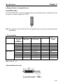
S Has the correct product been delivered (i.e., the correct model number and specifications)? Check the nameplate as shown below.
Inverter model
Input specification
Output specification
S Has the product been damaged in shipping?
S Are any screws or bolts loose?
Notice:
OMRON products are manufactured for use according to proper procedures by a qualified
operator and only for the purposes described in this manual.
The following conventions are used to indicate and classify precautions in this manual.
Always heed the information provided with them. Failure to heed precautions can result in
injury to people or damage to property.
!
DANGER
Indicates an imminently hazardous situation which, if not avoided, will result in death
or serious injury.
!
WARNING
Indicates a potentially hazardous situation which, if not avoided, could result in death
or serious injury.
! Caution
Indicates a potentially hazardous situation which, if not avoided, may result in minor
or moderate injury, or property damage.
OMRON Product References
All OMRON products are capitalized in this manual. The word “Unit” is also capitalized when
it refers to an OMRON product, regardless of whether or not it appears in the proper name
of the product.
The abbreviation “Ch,” which appears in some displays and on some OMRON products,
often means “word” and is abbreviated “Wd” in documentation in this sense.
The abbreviation “PC” means Programmable Controller and is not used as an abbreviation
for anything else.
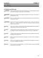
Visual Aids
The following headings appear in the left column of the manual to help you locate different
types of information.
Note Indicates information of particular interest for efficient and convenient operation of the product.
OMRON, 1996
All rights reserved. No part of this publication may be reproduced, stored in a retrieval system, or transmitted,
in any form, or by any means, mechanical, electronic, photocopying, recording, or otherwise, without the prior
written permission of OMRON.
No patent liability is assumed with respect to the use of the information contained herein. Moreover, because
OMRON is constantly striving to improve its high-quality products, the information contained in this manual
is subject to change without notice. Every precaution has been taken in the preparation of this manual. Nevertheless, OMRON assumes no responsibility for errors or omissions. Neither is any liability assumed for damages resulting from the use of the information contained in this publication.
General Precautions
Observe the following precautions when using the SYSDRIVE Inverters and peripheral
devices.
This manual may include illustrations of the product with protective covers removed in order
to describe the components of the product in detail. Make sure that these protective covers
are on the product before use.
Consult your OMRON representative when using the product after a long period of storage.
!
WARNING
Do not touch the inside of the Inverter. Doing so may result in electrical shock.
!
WARNING
Operation, maintenance, or inspection must be performed after turning OFF the
power supply, confirming that the CHARGE indicator (or status indicators) are OFF,
and after waiting for the time specified on the front cover. Not doing so may result in
electrical shock.
!
WARNING
Do not damage, pull on, apply stress to, place heavy objects on, or pinch the cables.
Doing so may result in electrical shock.
!
WARNING
Do not touch the rotating parts of the motor under operation. Doing so may result in
injury.
!
WARNING
Do not modify the product. Doing so may result in injury or damage to the product.
! Caution
Do not store, install, or operate the product in the following places. Doing so may
result in electrical shock, fire or damage to the product.
S Locations subject to direct sunlight.
S Locations subject to temperatures or humidity outside the range specified in the
specifications.
S Locations subject to condensation as the result of severe changes in temperature.
S Locations subject to corrosive or flammable gases.
S Locations subject to exposure to combustibles.
S Locations subject to dust (especially iron dust) or salts.
S Locations subject to exposure to water, oil, or chemicals.
S Locations subject to shock or vibration.
! Caution
Do not touch the Inverter radiator, regenerative resistor, or Servomotor while the
power is being supplied or soon after the power is turned OFF. Doing so may result in
a skin burn due to the hot surface.
! Caution
Do not conduct a dielectric strength test on any part of the Inverter. Doing so may
result in damage to the product or malfunction.
! Caution
Take appropriate and sufficient countermeasures when installing systems in the following locations. Not doing so may result in equipment damage.
S Locations subject to static electricity or other forms of noise.
S Locations subject to strong electromagnetic fields and magnetic fields.
S Locations subject to possible exposure to radioactivity.
S Locations close to power supplies.
Transportation Precautions
! Caution
Do not hold by front cover or panel , instead, hold by the radiation fin (heat sink) while
transporting the product. Doing so may result in injury.
! Caution
Do not pull on the cables. Doing so may result in damage to the product or malfunction.
! Caution
Use the eye-bolts only for transporting the Inverter. Using them for transporting the
machinery may result in injury or malfunction.
Installation Precautions
!
WARNING
Provide an appropriate stopping device on the machine side to secure safety. (A
holding brake is not a stopping device for securing safety.) Not doing so may result in
injury.
!
WARNING
Provide an external emergency stopping device that allows an instantaneous stop of
operation and power interruption. Not doing so may result in injury.
! Caution
Be sure to install the product in the correct direction and provide specified clearances between the Inverter and control panel or with other devices. Not doing so
may result in fire or malfunction.
! Caution
Do not allow foreign objects to enter inside the product. Doing so may result in fire or
malfunction.
! Caution
Do not apply any strong impact. Doing so may result in damage to the product or
malfunction.
Wiring Precautions
!
WARNING
Wiring must be performed only after confirming that the power supply has been
turned OFF. Not doing so may result in electrical shock.
!
WARNING
Wiring must be performed by authorized personnel. Not doing so may result in
electrical shock or fire.
!
WARNING
Be sure to confirm operation only after wiring the emergency stop circuit. Not doing
so may result in injury.
!
WARNING
Always connect the ground terminals to a ground of 100 Ω or less for the 200-V AC
class, or 10 Ω or less for the 400-V AC class. Not connecting to a proper ground may
result in electrical shock.
! Caution
Install external breakers and take other safety measures against short-circuiting in
external wiring. Not doing so may result in fire.
! Caution
Confirm that the rated input voltage of the Inverter is the same as the AC power supply voltage. An incorrect power supply may result in fire, injury, or malfunction.
! Caution
Connect the Braking Resistor and Braking Resistor Unit as specified in the manual.
Not doing so may result in fire.
! Caution
Be sure to wire correctly and securely. Not doing so may result in injury or damage to
the product.
! Caution
Be sure to firmly tighten the screws on the terminal block. Not doing so may result in
fire, injury, or damage to the product.
! Caution
Do not connect an AC power to the U, V, or W output. Doing so may result in damage
to the product or malfunction.
Operation and Adjustment Precautions
!
WARNING
Turn ON the input power supply only after mounting the front cover, terminal covers,
bottom cover, Operator, and optional items. Not doing so may result in electrical
shock.
!
WARNING
Do not remove the front cover, terminal covers, bottom cover, Operator, or optional
items while the power is being supplied. Doing so may result in electrical shock or
damage to the product.
!
WARNING
Do not operate the Operator or switches with wet hands. Doing so may result in
electrical shock.
!
WARNING
Do not touch the inside of the Inverter. Doing so may result in electrical shock.
!
WARNING
Do not come close to the machine when using the error retry function because the
machine may abruptly start when stopped by an alarm. Doing so may result in injury.
!
WARNING
Do not come close to the machine immediately after resetting momentary power
interruption to avoid an unexpected restart (if operation is set to be continued in the
processing selection function after momentary power interruption is reset). Doing so
may result in injury.
!
WARNING
Provide a separate emergency stop switch because the STOP Key on the Operator
is valid only when function settings are performed. Not doing so may result in injury.
!
WARNING
Be sure to confirm that the RUN signal is turned OFF before turning ON the power
supply, resetting the alarm, or switching the LOCAL/REMOTE selector. Doing so
while the RUN signal is turned ON may result in injury.
! Caution
Be sure to confirm permissible ranges of motors and machines before operation
because the Inverter speed can be easily changed from low to high. Not doing so
may result in damage to the product.
! Caution
Provide a separate holding brake when necessary. Not doing so may result in injury.
! Caution
Do not perform a signal check during operation. Doing so may result in injury or damage to the product.
! Caution
Do not carelessly change settings. Doing so may result in injury or damage to the
product.
Maintenance and Inspection Precautions
!
WARNING
Do not touch the Inverter terminals while the power is being supplied.
!
WARNING
Maintenance or inspection must be performed only after turning OFF the power
supply, confirming that the CHARGE indicator (or status indicators) is turned OFF,
and after waiting for the time specified on the front cover. Not doing so may result in
electrical shock.
!
WARNING
Maintenance, inspection, or parts replacement must be performed by authorized
personnel. Not doing so may result in electrical shock or injury.
!
WARNING
Do not attempt to take the Unit apart or repair. Doing either of these may result in
electrical shock or injury.
! Caution
Carefully handle the Inverter because it uses semiconductor elements. Careless
handling may result in malfunction.
! Caution
Do not change wiring, disconnect connectors, the Operator, or optional items, or
replace fans while power is being supplied. Doing so may result in injury, damage to
the product, or malfunction.
Warning Labels
Warning labels are pasted on the product as shown in the following illustration. Be sure to
follow the instructions given there.
H Warning Labels
H Contents of Warning
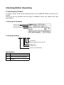
Checking Before Unpacking
H Checking the Product
On delivery, always check that the delivered product is the SYSDRIVE 3G3MV Inverter that you
ordered.
Should you find any problems with the product, immediately contact your nearest local sales
representative.
D Checking the Nameplate
Inverter model
3G3FV-A2001
Input specifications
Output specifications
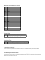
D Checking the Model
3G3FV-A2037-CUE
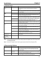
Specifications
Maximum applicable motor capacity
Voltage class
Installation type
Series name: 3G3MV Series
Specifications
None
-E
-CE
-CUE
Japanese model
English model
Model conforming to EN standards
Model conforming to EN and UL/cUL
standards
Maximum Applicable Motor Capacity
004
007
015
022
037
055
075
110
150
185
220
300
370
450
550
750
11K
16K
18K
22K
30K
0.4 kW
0.75 kW
1.5 kW
2.2 kW
3.7 kW
5.5 kW
7.5 kW
11 kW
15 kW
18.5 kW
22 kW
30 kW
37 kW
45 kW
55 kW
75 kW
110 kW
160 kW
185 kW
220 kW
300 kW
Voltage Class
2
4
Three-phase 200-V AC input (200-V class)
Three-phase 400-V AC input (400-V class)
Installation Type
A
C
Panel-mounting (IP10 min.) or closed wall-mounting models
Closed wall-mounting models (IP00 min.)
D Checking for Damage
Check the overall appearance and check for damage or scratches resulting from transportation.
H Checking the Accessories
Note that this manual is the only accessory provided with the 3G3MV. Set screws and other necessary
parts must be provided by the user.
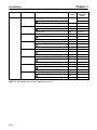
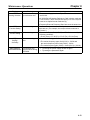
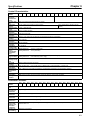
About this Manual
This manual is divided into the chapters described in the following table. Information is organized by
application area to enable you to use the manual more efficiently.
Chapter
Chapter 1 Overview
Chapter 2 Installation
Chapter 3 Preparing for Operation
Chapter 4 Trial Operation
Chapter 5 Basic Operation
Chapter 6 Advanced Operation
Chapter 7 List of Parameters
Chapter 8 Maintenance Operations
Chapter 9 Specifications
Contents
Describes features and nomenclature. Also describes new functions.
Provides information required for system design, such as product
dimensions, installation dimensions, peripheral device design
information, and peripheral device selection information.
Describes nomenclature, Digital Operator procedures, such as key
operations, for operating and monitoring Inverters, and mode contents
and configuration.
Describes the method for controlling operation through a Digital
Operator to perform trial operation of the system.
Describes basic Inverter control functions for users not familiar with
Inverters. The functions that must be understood to drive a motor with
an Inverter are described. Each of the four control modes of the
3G3FV-series Inverters is described in order alone with the settings
required for all modes and individual modes. Refer to the information
for all control modes and then to items required for the control mode
you will be using.
Describes all of the functions provided by the Inverter. These functions
will enable more advanced applications, and includes functions that
will improve motor control through the Inverter, such as
responsiveness (torque characteristics), increasing speed accuracy,
PID control, torque limits, torque controls, overtorque detection,
protective functions, and other functions. Each of the four control
modes of the 3G3FV-series Inverters is described in order alone with
the characteristics of each mode and fountains common to all modes.
Refer to the information for all control modes and then to items
required for the control mode you will be using.
Lists basic information on Inverter parameters as a reference for users
already familiar with Inverter operation. Parameters are listed in order
with the page numbers of further information for easy reference.
Provides maintenance, inspection, fault analysis, and troubleshooting
information required to deal with problems that may occur during
operation.
Provides Inverter specifications, as well as the specifications and
dimensions of peripheral devices.
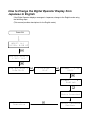
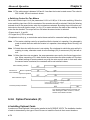
How to Change the Digital Operator Display from
Japanese to English
If the Digital Operator displays messages in Japanese, change to the English mode using
the following steps.
(This manual provides descriptions for the English mode.)
Power ON
<3J=3 <Z2
U1-01= 0.00 HZ
FV* S0D^>]@8 *
D^W2L^ S0D^
FV* S0D^>]@8 *
6]7.3>/C2
9^]:^>]@8
FN]:^
1 **
A1-00=
FN]:^
A1-00=
0
English
Entry Accepted
** Main Menu **
Operation
Select Language
English
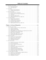
Table of Contents
Chapter 1. Introduction . . . . . . . . . . . . . . . . . . . . . . . . . . . . . . . . . . . . . 1-1
1-1 Function . . . . . . . . . . . . . . . . . . . . . . . . . . . . . . . . . . . . . . . . . . . . . . . . . . . . . . . . . . . . . . . . . . .
1-2 Nomenclature . . . . . . . . . . . . . . . . . . . . . . . . . . . . . . . . . . . . . . . . . . . . . . . . . . . . . . . . . . . . . . .
1-3 New Functions . . . . . . . . . . . . . . . . . . . . . . . . . . . . . . . . . . . . . . . . . . . . . . . . . . . . . . . . . . . . . .
1-3-1 Software Ver. VSG101040 . . . . . . . . . . . . . . . . . . . . . . . . . . . . . . . . . . . . . . . . . . . . . .
1-3-2 Software Ver. VSG101043 . . . . . . . . . . . . . . . . . . . . . . . . . . . . . . . . . . . . . . . . . . . . . .
1-3-3 Software Ver. VSG101113 . . . . . . . . . . . . . . . . . . . . . . . . . . . . . . . . . . . . . . . . . . . . . .
1-3-4 Software Ver. VSG101114 . . . . . . . . . . . . . . . . . . . . . . . . . . . . . . . . . . . . . . . . . . . . . .
1-2
1-8
1-11
1-11
1-12
1-13
1-17
Chapter 2. Installation . . . . . . . . . . . . . . . . . . . . . . . . . . . . . . . . . . . . . . 2-1
2-1 Mounting . . . . . . . . . . . . . . . . . . . . . . . . . . . . . . . . . . . . . . . . . . . . . . . . . . . . . . . . . . . . . . . . . .
2-1-1 Dimensions . . . . . . . . . . . . . . . . . . . . . . . . . . . . . . . . . . . . . . . . . . . . . . . . . . . . . . . . . .
2-1-2 Installation Conditions . . . . . . . . . . . . . . . . . . . . . . . . . . . . . . . . . . . . . . . . . . . . . . . . .
2-2 Wiring . . . . . . . . . . . . . . . . . . . . . . . . . . . . . . . . . . . . . . . . . . . . . . . . . . . . . . . . . . . . . . . . . . . .
2-2-1 Removing and Mounting the Front Cover . . . . . . . . . . . . . . . . . . . . . . . . . . . . . . . . . .
2-2-2 Terminals . . . . . . . . . . . . . . . . . . . . . . . . . . . . . . . . . . . . . . . . . . . . . . . . . . . . . . . . . . . .
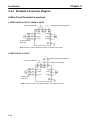
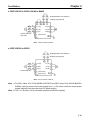
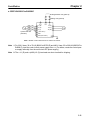
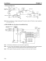
2-2-3 Standard Connection Diagram . . . . . . . . . . . . . . . . . . . . . . . . . . . . . . . . . . . . . . . . . . .
2-2-4 Wiring Around the Main Circuit . . . . . . . . . . . . . . . . . . . . . . . . . . . . . . . . . . . . . . . . .
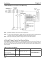
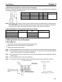
2-2-5 Wiring Control Circuit Terminals . . . . . . . . . . . . . . . . . . . . . . . . . . . . . . . . . . . . . . . . .
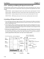
2-2-6 Installing and Wiring PG Speed Control Cards . . . . . . . . . . . . . . . . . . . . . . . . . . . . . .
2-2
2-2
2-8
2-11
2-12
2-14
2-18
2-23
2-39
2-40
Chapter 3. Preparing for Operation . . . . . . . . . . . . . . . . . . . . . . . . . . . 3-1
3-1
3-2
3-3
3-4
3-5
3-6
3-7
3-8
Using the Digital Operator . . . . . . . . . . . . . . . . . . . . . . . . . . . . . . . . . . . . . . . . . . . . . . . . . . . .
Modes . . . . . . . . . . . . . . . . . . . . . . . . . . . . . . . . . . . . . . . . . . . . . . . . . . . . . . . . . . . . . . . . . . . . .
Operation Mode . . . . . . . . . . . . . . . . . . . . . . . . . . . . . . . . . . . . . . . . . . . . . . . . . . . . . . . . . . . . .
Initialize Mode . . . . . . . . . . . . . . . . . . . . . . . . . . . . . . . . . . . . . . . . . . . . . . . . . . . . . . . . . . . . . .
Program Mode . . . . . . . . . . . . . . . . . . . . . . . . . . . . . . . . . . . . . . . . . . . . . . . . . . . . . . . . . . . . . .
Auto-tuning Mode . . . . . . . . . . . . . . . . . . . . . . . . . . . . . . . . . . . . . . . . . . . . . . . . . . . . . . . . . . .
Modified Constants Mode . . . . . . . . . . . . . . . . . . . . . . . . . . . . . . . . . . . . . . . . . . . . . . . . . . . . .
Operation Mode Selection Key and Local/Remote Selection Input . . . . . . . . . . . . . . . . . . . . .
3-2
3-3
3-10
3-18
3-25
3-28
3-30
3-31
Chapter 4. Trial Operation . . . . . . . . . . . . . . . . . . . . . . . . . . . . . . . . . . . 4-1
4-1 Procedure . . . . . . . . . . . . . . . . . . . . . . . . . . . . . . . . . . . . . . . . . . . . . . . . . . . . . . . . . . . . . . . . . . 4-3
4-2 Operation Example . . . . . . . . . . . . . . . . . . . . . . . . . . . . . . . . . . . . . . . . . . . . . . . . . . . . . . . . . . 4-5
4-2-1 Power Connection . . . . . . . . . . . . . . . . . . . . . . . . . . . . . . . . . . . . . . . . . . . . . . . . . . . . . 4-5
4-2-2 Checking the Display Status . . . . . . . . . . . . . . . . . . . . . . . . . . . . . . . . . . . . . . . . . . . . . 4-5
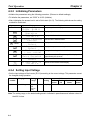
4-2-3 Initializing Parameters . . . . . . . . . . . . . . . . . . . . . . . . . . . . . . . . . . . . . . . . . . . . . . . . . 4-6
4-2-4 Setting Input Voltage . . . . . . . . . . . . . . . . . . . . . . . . . . . . . . . . . . . . . . . . . . . . . . . . . . 4-6
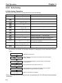
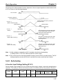
4-2-5 Auto-tuning . . . . . . . . . . . . . . . . . . . . . . . . . . . . . . . . . . . . . . . . . . . . . . . . . . . . . . . . . . 4-8
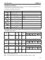
4-2-6 No-load Operation . . . . . . . . . . . . . . . . . . . . . . . . . . . . . . . . . . . . . . . . . . . . . . . . . . . . 4-10
4-2-7 Actual Load Operation . . . . . . . . . . . . . . . . . . . . . . . . . . . . . . . . . . . . . . . . . . . . . . . . . 4-11
Chapter 5. Basic Operation . . . . . . . . . . . . . . . . . . . . . . . . . . . . . . . . . . 5-1
5-1 Common Settings . . . . . . . . . . . . . . . . . . . . . . . . . . . . . . . . . . . . . . . . . . . . . . . . . . . . . . . . . . . .
5-1-1 Setting the Access Level and Control Mode . . . . . . . . . . . . . . . . . . . . . . . . . . . . . . . .
5-1-2 Frequency Reference Settings from Control Circuit Terminals . . . . . . . . . . . . . . . . . .
5-1-3 Frequency Reference Settings from Digital Operator . . . . . . . . . . . . . . . . . . . . . . . . .
5-1-4 Run Source and Responsiveness Settings . . . . . . . . . . . . . . . . . . . . . . . . . . . . . . . . . . .
5-1-5 Acceleration/Deceleration Time Settings . . . . . . . . . . . . . . . . . . . . . . . . . . . . . . . . . . .
5-1-6 Disabling Reverse Operation (b1-04) . . . . . . . . . . . . . . . . . . . . . . . . . . . . . . . . . . . . . .
5-1-7 Selecting the Stopping Method (b1-03) . . . . . . . . . . . . . . . . . . . . . . . . . . . . . . . . . . . .
5-1-8 Multi-function Input Settings (H1-01 through H1-06) . . . . . . . . . . . . . . . . . . . . . . . . .
5-2
5-2
5-4
5-8
5-10
5-11
5-13
5-13
5-15
Table of Contents
5-2 Open-loop Vector Control . . . . . . . . . . . . . . . . . . . . . . . . . . . . . . . . . . . . . . . . . . . . . . . . . . . . .
5-2-1 Auto-tuning Procedure . . . . . . . . . . . . . . . . . . . . . . . . . . . . . . . . . . . . . . . . . . . . . . . . .
5-2-2 Auto-tuning Faults . . . . . . . . . . . . . . . . . . . . . . . . . . . . . . . . . . . . . . . . . . . . . . . . . . . .
5-3 V/f Control . . . . . . . . . . . . . . . . . . . . . . . . . . . . . . . . . . . . . . . . . . . . . . . . . . . . . . . . . . . . . . . . .
5-3-1 Setting the Motor Parameters . . . . . . . . . . . . . . . . . . . . . . . . . . . . . . . . . . . . . . . . . . . .
5-3-2 V/f Pattern Selection (E1-03) . . . . . . . . . . . . . . . . . . . . . . . . . . . . . . . . . . . . . . . . . . . .
5-4 Flux Vector Control . . . . . . . . . . . . . . . . . . . . . . . . . . . . . . . . . . . . . . . . . . . . . . . . . . . . . . . . . .
5-4-1 PG Speed Control Card Settings . . . . . . . . . . . . . . . . . . . . . . . . . . . . . . . . . . . . . . . . . .
5-4-2 Setting the Zero-speed Operation Parameters . . . . . . . . . . . . . . . . . . . . . . . . . . . . . . .
5-4-3 Auto-tuning . . . . . . . . . . . . . . . . . . . . . . . . . . . . . . . . . . . . . . . . . . . . . . . . . . . . . . . . . .
5-4-4 Speed Loop (ASR) Structure . . . . . . . . . . . . . . . . . . . . . . . . . . . . . . . . . . . . . . . . . . . .
5-4-5 Adjusting Speed Control Loop (ASR) Gain . . . . . . . . . . . . . . . . . . . . . . . . . . . . . . . . .
5-5 V/f Control with PG . . . . . . . . . . . . . . . . . . . . . . . . . . . . . . . . . . . . . . . . . . . . . . . . . . . . . . . . . .
5-5-1 Setting the Motor Parameters . . . . . . . . . . . . . . . . . . . . . . . . . . . . . . . . . . . . . . . . . . . .
5-5-2 V/f Pattern Selection (E1-03) . . . . . . . . . . . . . . . . . . . . . . . . . . . . . . . . . . . . . . . . . . . .
5-5-3 PG Speed Control Card Settings . . . . . . . . . . . . . . . . . . . . . . . . . . . . . . . . . . . . . . . . . .
5-5-4 Speed Loop (ASR) Structure . . . . . . . . . . . . . . . . . . . . . . . . . . . . . . . . . . . . . . . . . . . .
5-5-5 Adjusting Speed Control Loop (ASR) Gain . . . . . . . . . . . . . . . . . . . . . . . . . . . . . . . . .
5-20
5-20
5-21
5-23
5-23
5-24
5-29
5-29
5-32
5-35
5-38
5-40
5-43
5-43
5-44
5-45
5-48
5-49
Chapter 6. Advanced Operation . . . . . . . . . . . . . . . . . . . . . . . . . . . . . . 6-1
6-1 Open-loop Vector Control . . . . . . . . . . . . . . . . . . . . . . . . . . . . . . . . . . . . . . . . . . . . . . . . . . . . .
6-1-1 Summary of Open-loop Vector Control Functions . . . . . . . . . . . . . . . . . . . . . . . . . . . .
6-1-2 Torque Limit Function . . . . . . . . . . . . . . . . . . . . . . . . . . . . . . . . . . . . . . . . . . . . . . . . .
6-1-3 Adjusting Speed Feedback . . . . . . . . . . . . . . . . . . . . . . . . . . . . . . . . . . . . . . . . . . . . . .
6-1-4 Setting Magnetic Flux Characteristics for Open-loop Vector Control . . . . . . . . . . . . .
6-1-5 Operation for Saturated Output Voltage . . . . . . . . . . . . . . . . . . . . . . . . . . . . . . . . . . . .
6-1-6 Startup Torque Compensation . . . . . . . . . . . . . . . . . . . . . . . . . . . . . . . . . . . . . . . . . . .
6-1-7 Selecting Auto-tuning Carrier Frequency . . . . . . . . . . . . . . . . . . . . . . . . . . . . . . . . . .
6-1-8 Setting/Adjusting Motor Parameters . . . . . . . . . . . . . . . . . . . . . . . . . . . . . . . . . . . . . .
6-2 Normal V/f Control . . . . . . . . . . . . . . . . . . . . . . . . . . . . . . . . . . . . . . . . . . . . . . . . . . . . . . . . . .
6-2-1 Summary of V/f Control Functions . . . . . . . . . . . . . . . . . . . . . . . . . . . . . . . . . . . . . . .
6-2-2 Energy-saving Control Function . . . . . . . . . . . . . . . . . . . . . . . . . . . . . . . . . . . . . . . . . .
6-2-3 Hunting-prevention Function . . . . . . . . . . . . . . . . . . . . . . . . . . . . . . . . . . . . . . . . . . . .
6-2-4 Setting Motor Parameters . . . . . . . . . . . . . . . . . . . . . . . . . . . . . . . . . . . . . . . . . . . . . . .
6-3 Flux Vector Control . . . . . . . . . . . . . . . . . . . . . . . . . . . . . . . . . . . . . . . . . . . . . . . . . . . . . . . . . .
6-3-1 Summary of Flux Vector Control Functions . . . . . . . . . . . . . . . . . . . . . . . . . . . . . . . . .
6-3-2 Droop Control Function . . . . . . . . . . . . . . . . . . . . . . . . . . . . . . . . . . . . . . . . . . . . . . . .
6-3-3 Zero-servo Function (Position-lock) . . . . . . . . . . . . . . . . . . . . . . . . . . . . . . . . . . . . . . .
6-3-4 Torque Control . . . . . . . . . . . . . . . . . . . . . . . . . . . . . . . . . . . . . . . . . . . . . . . . . . . . . . .
6-3-5 Speed/Torque Control Switching Function . . . . . . . . . . . . . . . . . . . . . . . . . . . . . . . . .
6-3-6 Torque Limit Function . . . . . . . . . . . . . . . . . . . . . . . . . . . . . . . . . . . . . . . . . . . . . . . . .
6-3-7 Setting/Adjusting Motor Parameters . . . . . . . . . . . . . . . . . . . . . . . . . . . . . . . . . . . . . .
6-3-8 Operation for Saturated Output Voltage . . . . . . . . . . . . . . . . . . . . . . . . . . . . . . . . . . . .
6-3-9 Selecting Auto-tuning Carrier Frequency . . . . . . . . . . . . . . . . . . . . . . . . . . . . . . . . . .
6-4 V/f Control With PG Feedback . . . . . . . . . . . . . . . . . . . . . . . . . . . . . . . . . . . . . . . . . . . . . . . . .
6-4-1 Summary of V/f Control With PG Feedback Functions . . . . . . . . . . . . . . . . . . . . . . . .
6-4-2 Energy-saving Control Function . . . . . . . . . . . . . . . . . . . . . . . . . . . . . . . . . . . . . . . . . .
6-4-3 Hunting-prevention Function . . . . . . . . . . . . . . . . . . . . . . . . . . . . . . . . . . . . . . . . . . . .
6-4-4 Setting Motor Parameters . . . . . . . . . . . . . . . . . . . . . . . . . . . . . . . . . . . . . . . . . . . . . . .
6-2
6-2
6-3
6-5
6-6
6-6
6-7
6-8
6-8
6-12
6-12
6-13
6-14
6-15
6-16
6-16
6-17
6-18
6-20
6-27
6-28
6-31
6-34
6-35
6-36
6-36
6-37
6-38
6-39
Table of Contents
6-5 Common Functions . . . . . . . . . . . . . . . . . . . . . . . . . . . . . . . . . . . . . . . . . . . . . . . . . . . . . . . . . .
6-5-1 Summary of Common Control Functions . . . . . . . . . . . . . . . . . . . . . . . . . . . . . . . . . .
6-5-2 Application Parameters (b) . . . . . . . . . . . . . . . . . . . . . . . . . . . . . . . . . . . . . . . . . . . . . .
6-5-3 Tuning Parameters (C) . . . . . . . . . . . . . . . . . . . . . . . . . . . . . . . . . . . . . . . . . . . . . . . . .
6-5-4 Reference Parameters (d) . . . . . . . . . . . . . . . . . . . . . . . . . . . . . . . . . . . . . . . . . . . . . . .
6-5-5 Motor Parameters (E) . . . . . . . . . . . . . . . . . . . . . . . . . . . . . . . . . . . . . . . . . . . . . . . . . .
6-5-6 Option Parameters (F) . . . . . . . . . . . . . . . . . . . . . . . . . . . . . . . . . . . . . . . . . . . . . . . . . .
6-5-7 External Terminal Functions: H . . . . . . . . . . . . . . . . . . . . . . . . . . . . . . . . . . . . . . . . . .
6-5-8 Protective Functions: L . . . . . . . . . . . . . . . . . . . . . . . . . . . . . . . . . . . . . . . . . . . . . . . . .
6-5-9 Operator Parameters: o . . . . . . . . . . . . . . . . . . . . . . . . . . . . . . . . . . . . . . . . . . . . . . . . .
6-40
6-40
6-41
6-58
6-64
6-66
6-70
6-76
6-97
6-110
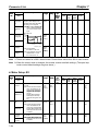
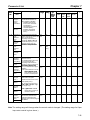
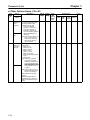
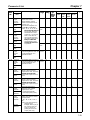
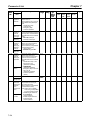
Chapter 7. Parameter Lists . . . . . . . . . . . . . . . . . . . . . . . . . . . . . . . . . . 7-1
7-1 Initialize Mode Parameters . . . . . . . . . . . . . . . . . . . . . . . . . . . . . . . . . . . . . . . . . . . . . . . . . . . .
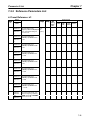
7-2 Program Mode Parameter List . . . . . . . . . . . . . . . . . . . . . . . . . . . . . . . . . . . . . . . . . . . . . . . . . .
7-2-1 Application Group: b . . . . . . . . . . . . . . . . . . . . . . . . . . . . . . . . . . . . . . . . . . . . . . . . . .
7-2-2 Tuning Parameters . . . . . . . . . . . . . . . . . . . . . . . . . . . . . . . . . . . . . . . . . . . . . . . . . . . .
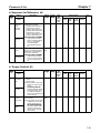
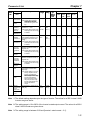
7-2-3 Reference Parameters List . . . . . . . . . . . . . . . . . . . . . . . . . . . . . . . . . . . . . . . . . . . . . .
7-2-4 Motor Constant Parameter Lists . . . . . . . . . . . . . . . . . . . . . . . . . . . . . . . . . . . . . . . . . .
7-2-5 Options Parameter Lists . . . . . . . . . . . . . . . . . . . . . . . . . . . . . . . . . . . . . . . . . . . . . . . .
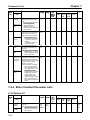
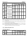
7-2-6 Terminal Parameter Lists . . . . . . . . . . . . . . . . . . . . . . . . . . . . . . . . . . . . . . . . . . . . . . .
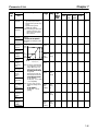
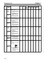
7-2-7 Protection Parameter Lists . . . . . . . . . . . . . . . . . . . . . . . . . . . . . . . . . . . . . . . . . . . . . .
7-2-8 Operator Parameter Lists . . . . . . . . . . . . . . . . . . . . . . . . . . . . . . . . . . . . . . . . . . . . . . .
7-3
7-5
7-5
7-13
7-21
7-24
7-29
7-35
7-43
7-50
Chapter 8. Maintenance Operations . . . . . . . . . . . . . . . . . . . . . . . . . . . 8-1
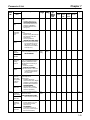
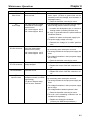
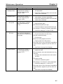
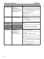
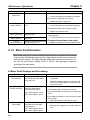
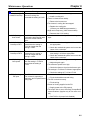
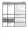
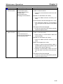
8-1 Protective and Diagnostic Functions . . . . . . . . . . . . . . . . . . . . . . . . . . . . . . . . . . . . . . . . . . . . . 8-2
8-1-1 Fault Detection . . . . . . . . . . . . . . . . . . . . . . . . . . . . . . . . . . . . . . . . . . . . . . . . . . . . . . . 8-2
8-1-2 Minor Fault Detection . . . . . . . . . . . . . . . . . . . . . . . . . . . . . . . . . . . . . . . . . . . . . . . . . . 8-8
8-1-3 Operation Errors . . . . . . . . . . . . . . . . . . . . . . . . . . . . . . . . . . . . . . . . . . . . . . . . . . . . . . 8-12
8-2 Troubleshooting . . . . . . . . . . . . . . . . . . . . . . . . . . . . . . . . . . . . . . . . . . . . . . . . . . . . . . . . . . . . . 8-14
8-3 Maintenance and Inspection . . . . . . . . . . . . . . . . . . . . . . . . . . . . . . . . . . . . . . . . . . . . . . . . . . . 8-22
Chapter 9. Specifications . . . . . . . . . . . . . . . . . . . . . . . . . . . . . . . . . . . . 9-1
9-1 Inverter Specifications . . . . . . . . . . . . . . . . . . . . . . . . . . . . . . . . . . . . . . . . . . . . . . . . . . . . . . . .
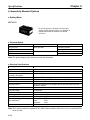
9-2 Option Specifications . . . . . . . . . . . . . . . . . . . . . . . . . . . . . . . . . . . . . . . . . . . . . . . . . . . . . . . .
9-2
9-7
Chapter 10. Appendix . . . . . . . . . . . . . . . . . . . . . . . . . . . . . . . . . . . . . . . 10-1
10-1 Notes on Using the Inverter for a Motor . . . . . . . . . . . . . . . . . . . . . . . . . . . . . . . . . . . . . . . . . . 10-2
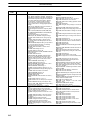
Revision History . . . . . . . . . . . . . . . . . . . . . . . . . . . . . . . . .
R-1
1
Chapter 1
Introduction
1-1
1-2
1-3
Function
Nomenclature
New Functions
Introduction
1-1
Chapter 1
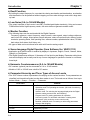
Functions
The general-purpose SYSDRIVE 3G3FV Inverter provides full current vector control
based on advanced control logic. An auto-tuning function allows for easy vector control.
The Digital Operator’s display area features a 2-line by 16-character liquid crystal display. Parameters can be displayed in up to seven languages, including Japanese. The
parameter settings and monitor items can be understood at a glance, providing an interactive feel during operation.
1-2
Chapter 1
Introduction
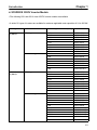
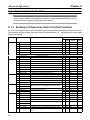
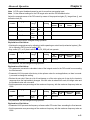
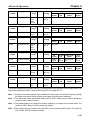
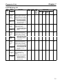
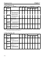
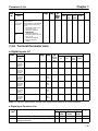
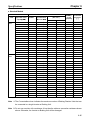
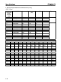
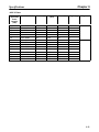
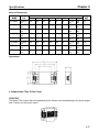
H SYSDRIVE 3G3FV Inverter Models
• The following 200- and 400-V class 3G3FV Inverter models are available.
• A total of 21 types of Inverters are available for maximum applicable motor capacities of 0.4 to 300 kW.
Voltage class
200-V class
( h
(3-phase)
)
Protective structure
NEMA1 type
y
Open chassis type
y
400-V class
( h
(3-phase)
)
NEMA1 type
y
Open chassis type
y
Maximum applied motor capacity
Model
0.4 kW
0.75 kW
1.5 kW
2.2 kW
3.7 kW
5.5 kW
7.5 kW
11 kW
15 kW
18.5 kW
22 kW
30 kW
37 kW
45 kW
55 kW
75 kW
3G3FV-A2004
3G3FV-A2007
3G3FV-A2015
3G3FV-A2022
3G3FV-A2037
3G3FV-A2055
3G3FV-A2075
3G3FV-A2110
3G3FV-A2150
3G3FV-B2185
3G3FV-B2220
3G3FV-B2300
3G3FV-B2370
3G3FV-B2450
3G3FV-B2550
3G3FV-B2750-E
0.4 kW
0.75 kW
1.5 kW
2.2 kW
3.7 kW
5.5 kW
7.5 kW
11 kW
15 kW
18.5 kW
22 kW
30 kW
37 kW
45 kW
55 kW
75 kW
110 kW
160 kW
185 kW
220 kW
300 kW
3G3FV-A4004
3G3FV-A4007
3G3FV-A4015
3G3FV-A4022
3G3FV-A4037
3G3FV-A4055
3G3FV-A4075
3G3FV-A4110
3G3FV-A4150
3G3FV-B4185
3G3FV-B4220
3G3FV-B4300
3G3FV-B4370
3G3FV-B4450
3G3FV-B4550
3G3FV-B4750-E
3G3FV-B411K-E
3G3FV-B416K-E
3G3FV-B418K-E
3G3FV-B422K-E
3G3FV-B430K-E
1-3
Chapter 1
Introduction
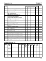
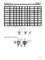
H Selection of Modes for Vector Control and V/f Control
• The 3G3FV has the following four control modes.
S Open-loop vector control (without PG*) [Factory default]
S Flux vector control (with PG)
S V/f control (without PG)
S V/f control (with PG)
*PG stands for “pulse generator” (encoder).
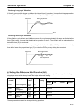
• Vector control is a method for removing interferences with magnetic flux and torque, and controlling
torque according to references. Current vector control independently controls magnetic flux current
and torque current by simultaneously controlling the motor’s primary current and its phases. This allows smooth rotation and high torque, along with accurate speed and torque control, at very low
speeds.
• Vector control can be replaced from the conventional V/f control system. If the motor parameter required for vector control is unknown, it can be set automatically with the auto-tuning function.
• The respective control modes are effective for the following applications:
S Open-loop vector control (without PG): General variable speed drive
S Flux vector control (with PG): Simple servo-drive, high-precision speed control, torque control
S V/f control (without PG): Conventional Inverter control mode. Used for multiple drives.
S V/f control (with PG): Simple speed feedback control
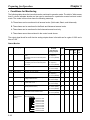
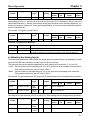
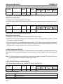
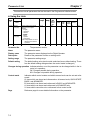
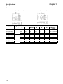
• The control characteristics for each mode are shown in the following table.
Vector control
Speed control range
Speed control precision
Starting torque
Without PG
1:100
±0.2%
150% at 1 Hz
With PG
1:1,000
±0.02%
150% at 0 Hz
V/f control
Without PG
With PG
1:40
1:40
±2 to 3%
±0.03%
150% at 3 Hz
H Auto-tuning Function
• This function is valid with vector control.
• The motor parameters are set automatically just by entering the motor’s rating plate value. This feature allows flux vector control to operate accurately with virtually any normal AC induction motor
regardless of the supplier.
H Torque Control
• This function is valid with flux vector control (with PG).
• Torque is controlled by taking multi-function analog input signals as torque references.
• Switching is possible between torque control and speed control.
H V/f Pattern Settings
• This function is valid for V/f control.
• Select a V/f pattern according to the application from among the 15 preset V/f patterns.
1-4
Chapter 1
Introduction
• Custom V/f pattern can be set.
H Frequency References
• The following five types of frequency references can be used to control the output frequency of the
Inverter.
S Numeric input from the Digital Operator
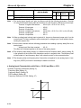
S Voltage input within a range from 0 to 10 V
S Voltage input within a range from 0 to ±10 V (With minus voltage, rotation is in the opposite direction of the run command.)
S Current input within a range from 4 to 20 mA
S Input by Optional Card
The Inverter can be set to use any of the above types by designating it with parameters.
• A maximum of eight frequency references can be registered in the Inverter. Including inching, this
enables multi-step speed operation with up to nine speed steps via remote multi-step reference
inputs.
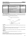
H PID Control
• The Inverter has a PID control function, enabling easy follow-up control.
• Follow-up control is a control method in which the Inverter varies the output frequency to match the
feedback value from the sensor with the set target value.
• Follow-up control can be applied to a variety of control operations, depending on the contents
detected by the sensor.
• PID control is available for the following applications.
S Speed control:
With a speed sensor, such as a tacho-generator, the Inverter regulates the
rotation speed of the motor regardless of the load of the motor or synchronizes the rotation speed of the motor with that of another motor.
S Pressure control:
With a pressure sensor, the Inverter performs constant pressure control.
S Flow-rate control:
By sensing the flow rate of a fluid, the Inverter performs precise flow-rate
control.
S Temperature control: With a temperature sensor, the Inverter performs temperature control by
fan speed.
H Zero-servo Control
• This function is valid with vector control (with PG).
• Even at a motor speed of zero (0 Hz), a torque of 150% of the motor’s rated torque can be generated
and the average servomotor holding power (stopping power) can be obtained.
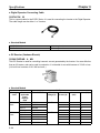
H Speed Control By Feedback
• This function is valid with PG.
• An optional PG Speed Control Card be used to enable feedback control for speeds, thereby improving
speed control accuracy.
1-5
Chapter 1
Introduction
H Dwell Function
• By holding the output frequency for a constant time during acceleration and deceleration, acceleration
and deceleration can be performed without stepping out even when driving a motor with a large startup load.
H Low Noise (0.4- to 160-kW Models)
• The output transistor of the Inverter is an IGBT (insulated gate bipolar transistor). Using a sine-wave
PWM method with a high-frequency carrier, the motor does not generate metallic noise.
H Monitor Function
• The following items can be monitored with the Digital Operator.
Frequency reference, output frequency, output current, motor speed, output voltage reference,
main-circuit DC voltage, output power, torque reference, status of input terminals, status of output
terminals, operating status, total operating time, software number, speed deviation value, PID feedback value, fault status, fault history, etc.
• All types of data can be monitored even with multi-function analog output.
H Seven-language Digital Operator (from Software Ver. VSG101113)
• Application as a global inverter is enabled by displays in Japanese, English, French, German, Italian,
Spanish, or Portuguese.
• The Digital Operator area utilizes a 16-character x 2-line liquid crystal display. Parameter setting items
and monitor display can be easily read in any of seven languages to operate the Inverter in a conversational style.
H Harmonic Countermeasures (0.4- to 160-kW Models)
• DC reactors (optional) can be connected to 0.4- to 15-kW models.
• Models of 18.5 to 160 kW have a built-in DC reactor.
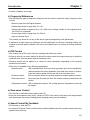
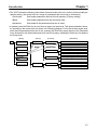
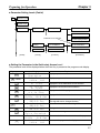
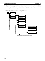
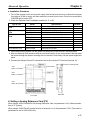
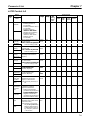
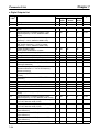
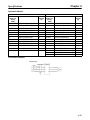
H Parameter Hierarchy and Three Types of Access Levels
• The 3G3FV has a number of parameters for carrying out the various functions. These parameters are
classified into hierarchical levels to make them easier to use. The levels are as follows, from top to
bottom: Mode Group Function Parameter.
Level name
Mode
Contents
Classified according to operation
Operation mode: For operating the Inverter. (All kinds of monitoring
are possible.)
Initialize mode: For selecting the language displayed at the Digital
Operator, setting access levels, and initializing.
Program mode: For setting parameters for operation.
Auto-tuning mode: For automatic calculation or setting motor
parameters. (Only under the vector control mode.)
Group
Function
Parameter
1-6
Modified constants mode: For setting or referencing parameters
changes after shipping.
Classified by application.
Classified by function.
Individual parameter settings.
Chapter 1
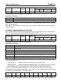
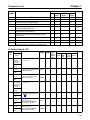
Introduction
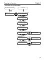
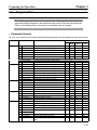
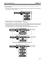
• The 3G3FV allows the following three kinds of access levels to be set in order to further simplify parameter setting. (An access level is a range of parameters that can be set or referenced.)
S Quick-start:
Sets/reads parameters required for trial operation. [Factory setting]
S Basic:
Sets/reads parameters that are commonly used.
S Advanced:
Sets/reads all the parameters that can be used.
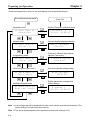
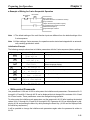
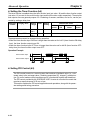
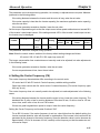
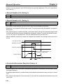
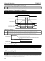
• In general, press the Enter Key to move from an upper to a lower level. This varies somewhat, however, according to the access level, as shown in the following diagram. For the Quick-start access level,
which has few parameters that can be set, pressing the Enter Key jumps directly to the Parameter
level; whereas for the Advanced access level, which has many, pressing the Enter Key first leads to
the Group level.
[Mode]
MENU
Operation mode
[Group]
b Application
[Function]
b1 Sequence
ADVANCED
Initialize mode
BASIC
b1-01 Reference source
b1-02 Run source
QUICK-START
b1-03 Stopping method
b2 DC braking
b2-01 Zero speed level
Program mode
b2-02 DC injection braking current
b3 Speed search
Auto-tuning
mode
Modified
constants mode
[Parameter]
b3-01 Beginning speed search
b3-02 Speed search operation current
c Tuning
C1 Accel/Decel
C1-01 Accel Time 1
C1-02 Decel Time 1
1-7
Chapter 1
Introduction
1-2
Nomenclature
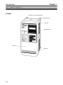
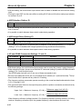
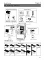
H Panel
Protection cover (top and bottom)
Mounting hole
Heat sink
Digital Operator
Front cover
Terminals
1-8
Chapter 1
Introduction
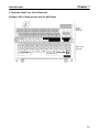
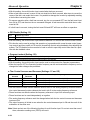
D Terminals (with Front Cover Removed)
Example: 200-V Class Inverter with 0.4-kW Output
Control
circuit
terminals
Main circuit
terminals
Power input
Braking Resistor
Motor output
1-9
Chapter 1
Introduction
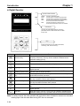
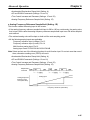
H Digital Operator
Operation Mode Indicators
DRIVE:
FWD:
REV:
SEQ:
REF:
Lit when in operation mode.
Lit when there is a forward command input.
Lit when there is a reverse command input.
Lit when the forward/reverse command from
the control circuit terminal is enabled.
Lit when the frequency reference from
control circuit terminals 13 and 14 is enabled.
Data Display
Two-line LCD that displays data for monitoring,
parameter names, and set values with 16 characters per line.
Keys
Execute operations such as setting parameters,
monitoring, JOG, and auto-tuning.
Key
Name
Operation Mode
Selection Key
Menu Key
Function
Switches between Operator and parameter setting (run command and
frequency reference). This key can be enabled or disabled with a
parameter setting (o2-02).
Displays each mode.
Escape Key
Returns to the status before the Enter Key is pressed.
Jog Key
Enables JOG operation when the 3G3FV is in operation with the
Digital Operator.
Selects the rotation direction of the motor when the 3G3FV is in
operation with the Digital Operator.
Selects digits for parameter settings. Also acts as the reset key when
an fault has occurred. (see note)
Selects modes, groups, functions, parameter names, and set values.
This key increases numbers when pressed.
Selects modes, groups, functions, parameter names, and set values.
This key decreases numbers when pressed.
Enters modes, functions, parameters, and set values after they are
set.
Starts the 3G3FV running when the 3G3FV is in operation with the
Digital Operator.
Stops the 3G3FV running. This key can be enabled or disabled with a
parameter setting (o2-02) in operation with the control circuit terminal.
Forward/Reverse
Rotation Selection Key
Reset/Digit Selection
Key
Increment Key
Decrement Key
Enter Key
Run Key
Stop Key
Note For safety reasons, the reset operation will not function when a forward or reverse run command
is being input. Use the reset after turning OFF the run command.
1-10
Introduction
1-3
Chapter 1
New Functions
The following software versions have been implemented for the 3G3FV Series to add
and upgrade functions.
August 1996: Software Ver. VSG101032 (S1032)
April 1997:
Software Ver. VSG101040 (S1040)
Sept. 1998: Software Ver. VSG101043 (S1043)
Sept. 1999: Software Ver. VSG101113 (S1113)
Sept. 2000: Software Ver. VSG101114 (S1114)
The software version can be confirmed using the 5-digit number display for the FLASH
ID for U1-14.
This section describes the new functions and improvements for each software version.
Refer to Chapter 5 Basic Operation and Chapter 6 Advance Operation.
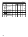
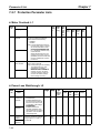
1-3-1 Software Ver. VSG101040
H CompoBus/D (DeviceNet) Communications Card
The CompoBus/D Communications Card can be used to connect the Inverter to a DeviceNet network.
The following function additions and improvements were made to support this new functionality.
D CompoBus/D Addition to the Frequency Reference Selection (Parameter b1-01)
A function was added to Frequency Reference Selection so that the Inverter frequency reference can
be input via DeviceNet communications.
D CompoBus/D Addition to the Run Source Selection (Parameter b1-02)
A function was added to Run Source Selection so that the Inverter run command can be input via DeviceNet communications.
D Communications External Fault Input (Parameters F9-01 to F9-03)
A function was added to support an external fault input from DeviceNet communications to stop the
Inverter when an error occurs. Sequence settings and operation designation for errors for the communications external fault input have been added.
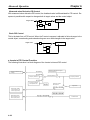
H Two-motor Switching Control
A function was added to enable switching control between two motors using one Inverter. The following
function additions were made to support this new functionality.
D Control Mode Setting Second Motor (Parameter E3-01)
A control mode setting was added so that the second motor can be set to a different mode.
Note The control mode setting was limited to 0 (V/f control without PG) or 2 (open-loop vector control), but
was changed in system version VSG101043 to support all control modes 0 to 3.
D V/f Pattern Settings for Second Motor (Parameters E4-01 to E4-06)
V/f pattern settings were added so that the second motor can be set to a different pattern.
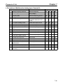
1-11
Introduction
Chapter 1
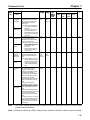
D Parameter Settings for Second Motor (Parameters E5-01 to E5-06)
Parameter settings were added so that different parameters can be set for the second motor.
H Inverter Output Noise Reduction
The noise output by 400-V class Inverters was reduced to reduce the affect on peripheral devices and
conform to EN standards. The following function improvements were added to support noise reduction.
D Default Setting Change for Carrier Frequency (Parameters C6-10 to C6-03)
The default carrier frequency setting for 400-V class Inverters was changed for the reduction of output
noise.
D Inverter Overload Function Change (OL2 Detection)
The Inverter overload detection function was changed because the Inverter’s rated output current
would be reduced if it was set higher than the carrier frequency.
Note If an Inverter overload is detected before a motor overload (0L1), lower the Inverter’s carrier frequency setting.
H Operation Selection after Switching to Remote Mode (Parameter b1-07)
Operation can be switched between Digital Operator and the frequency reference (b1-01) and between
Digital Operator and the run command (b1-01) by setting the local/remote selection using the Digital
Operator’s operation mode selection key or multi-function inputs (H1-01 to H1-06). The new function
can be used to enable or disable run commands when switching between the two forms of operation.
Note If the run command is enabled when switching operation, the Inverter can start operation immediately after switching operation. You must take appropriate safety measures when using this function.
H PG Disconnection Detection (PGO) Detection Time Setting (Parameter
F1-14)
A setting for PG disconnection (PGO) was added so that the detection time can be adjusted.
H New Functions for Multi-function Inputs 1 to 6 (H1-01 to H1-06)
The following functions were added to the multi-function inputs.
• Sample/hold function for the analog frequency reference (setting: 1E)
• PID control integral reset (setting: 30)
H Constant Output Area Settings for Flux Vector Control (E1-11 to E1-13)
Settings were added to enable controlling V/f characteristics to compensate voltage increases caused
by motor impedance when special motors, such as constant power-output motors and machine tool
shaft motors, are used in the constant output area.
H Vector Control Adjustment Settings (C3-05, C5-08, C8-09, C8-30)
Adjustment functions were added for vector control.
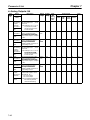
1-12
Introduction
Chapter 1
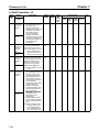
1-3-2 Software Ver. VSG101043
H CompoBus/D Communications Improved
The following functions were added for DeviceNet communications using a CompoBus/D Communications Card.
D Network Reference/Network Control Support (CompoBus/D Communications
Remote I/O)
A function was added to switch between inputting the Inverter frequency reference and a run command
using CompoBus/D communications from remote I/O. The Network Reference Bit can be turned ON
and OFF to switch between the method set for the frequency reference selection (b1-01) and a frequency reference from communications. In the same way, the Network Control Bit can be turned ON
and OFF to switch between the method set for the run source selection (b1-02) and a run command
from communications.
D Selection of Operation for Communications Errors (Parameter F9-06)
A setting was added to select the operation of the Inverter when a communications error is detected.
The selection can be made according to the application, e.g., a deceleration stop, free-run stop, continuing operation, etc.
D Torque Limit/Torque Reference Operation Selection via Communications
(Parameter F9-05)
A function was added to set the torque limit and torque reference (for torque control) from communications. This enables controlling torque operation from communications when the vector with PG control
mode is used.
Note The CompoBus/D Communications Card does not support the torque limit/torque reference function. Leave this function disabled.
H V/f Control with PG and Flux Vector Control for Two-motor Switching
Control (Parameter E3-01)
Settings were added for V/f Control with PG and Flux Vector Control to the control modes for the second
motor, enabling feedback control of 2 motors with 1 Inverter.
Note 1. Wiring for the pulse generator or encoder must be switched between the two motors.
Note 2. Use a pulse generator with the same specifications for both motors. (There is only one group
of parameters for the pulse generator.)
H Motor Parameter Autotuning (Parameter C8-30)
An autotuning function was added to autotune the motor parameters for special motors.
H Ground Fault Protection Operation Selection (Parameter: L8-10)
A setting was added to enabled and disable ground fault protection so that it can be disable when
required by the application.
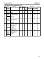
1-13
Introduction
Chapter 1
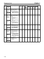
H Improved English Messages
The English messages displayed on the Digital Operator when the language is set to English (A1-00 =
0) have been improved.
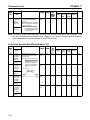
1-3-3 Software Ver. VSG101113
H Messages in 7 Languages
Application as a global inverter is enabled by displays in Japanese, English, French, German, Italian,
Spanish, or Portuguese.
H Low-speed Rotation Inconsistencies Greatly Reduced
Improvements in the current detector for vector control and in the responsiveness of current control
have greatly reduced torque ripple. This greatly reduces the low-speed inconsistencies for the 3G3FV
Series.
H Better Motor Speed Control Accuracy (Parameter C3-06)
Previously the motor speed control accuracy for vector control was greatly reduced when the limit of
Inverter’s voltage output was approached (a voltage greater than that of the input power supply cannot
be output). If the new output voltage control method is used, the output voltage will be controlled so that
the limit will not be reached, thus maintaining speed accuracy. The linear characteristic of torque control
has also been improved.
Note The current may increase by about 10% when this function is used. Be sure to select an Inverter
with ample output current capacity.
H Improved Motor Parameter Autotuning
A new method has been added for autotuning to produce greater accuracy.
H Improved PID Control
Additions have been made to PID control to increase the range of possible applications.
D PID Control Reverse Characteristics (Parameter b5-09)
Previously, only positive characteristic PID control, in which the feedback value increases when the
Inverter’s output frequency increases, was possible. In addition to this, reverse characteristic PID control is now possible, in which the feedback value decreases when the Inverter’s output frequency
increases.
D Frequency Reference + PID Control (Parameters b5-01 and b5-10)
A control method using the frequency reference and PID control has been added between the previous
frequency reference or PID control. This is ideal for applications in which the target speed is set, but fine
adjustments need to be made with PID control (such as tension control).
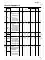
D Reverse Motor Control for PID Control (Parameter b5-11)
Motor rotation in only one direction was possible for previous PID control, but a reverse control setting
has been added to produce rotation in the reverse direction when the PID control result is negative.
1-14
Introduction
Chapter 1
D Feedback Loss Detection for PID Control (Parameters b5-12 to b5-14)
A function has been added to detect the loss of the feedback signal (e.g., as a result of line disconnection) and specify the operation when an error is detected.
D PID Control Target Value Added to Multi-function Inputs (Parameters H3-05 and
H3-09)
A function was added so that both the analog frequency reference and the PID control target value can
be input as analog signals for frequency reference + PID control.
D PID Integral Hold Added to Multi-function Inputs (Parameters H1-01 to H1-06)
A function was added to hold the the calculated integral value for PID control.
D Jump Frequencies Added to PID Control (Parameters d3-01 to d3-04)
The setting disabled frequencies (jump frequencies) have been enabled for PID control. This function
can be used to avoid frequency ranges that cause machine vibration during PID control.
H Motor Startup Responsiveness Improved
Compensation functions have been added to ensure faster motor startup.
D Startup Torque Compensation Function for Open-loop Vector Control (Parameters
C4-03 to C4-05)
A startup torque compensation function has been added to ensure faster startup for open-loop vector
control. If this function is used, high torque can be output immediately after startup to enable better control of lifting and lowering operations for large machines with high friction or cranes.
Note This function cannot be used during regenerative condition or when using a second motor.
D Magnetic Flex Compensation (Parameter b2-08)
Large-capacity motors have large electrical constants, and time is required to develop magnetic flex in
the motor after power has been turned ON. To improve this situation, a magnetic flex compensation
function has been added to the startup DC braking function, enabling magnetic flex to be built up in the
motor during DC braking.
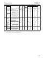
H Braking Function with Stall Prevention during Deceleration (Parameter
L3-04)
Even if regenerative energy is handled using a Braking Resistor or Braking Resistor Unit, overvoltages
(OV) can be detected during rapid deceleration. A stall prevention function for deceleration has been
added to the braking function (regeneration processing) to limit voltages when main circuit overvoltages
are likely to be detected, thus enabling faster braking without overvoltage detection.
H Inverter Overload (OL2) Protection Selection for Low-speed Operation
(Parameters L8-17 and L8-19)
An Inverter overload protection operation selection has been added to protect from overcurrent damage at low speeds. This function allows the best protection to be selected according to the application.
1-15
Chapter 1
Introduction
H Protection Setting for Motors for Vector Control (Parameter E1-02)
A special protection setting has been provided for vector-control motors, which have high resistance to
overloads even at low speeds.
H Bias Function for Analog Monitor Cards (Parameters F4-05 and F4-06)
A bias function has been added to the analog output from Analog Monitor Cards to enable adjusting the
offset voltage.
H NC Contact Emergency Stop Function for Multi-function Inputs
(Parameters d3-01 to d3-04)
An NC contact emergency stop function has been added to the previous NO function.
H Bias Function for Reverse Motor Control for Multi-function Inputs
(Parameters H3-05 and H3-09)
A function has been added for reverse motor operation by establishing a frequency bias 2 (setting: D)
for the multi-function inputs that causes reverse operation when the sum of the bias values is negative.
H Run Command Selection Outside of Drive Mode (Parameter b1-08)
A function has been added to enable or disable run command inputs in mode other than Drive Mode,
e.g., Program Mode or Initialize Mode.
Note If this function is used, a run command can be input and Inverter operation stared even when
adjusting parameters in Program Mode. Proper safety measures must be taken to prevent dangerous situations.
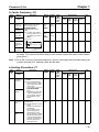
H Motor Core Loss Adjustment for Torque Compensation (Parameter
E2-10)
A motor core loss setting has been added to enable fine adjustment of torque compensation (totally
automatic torque boast) in V/f control without PG and V/f control with PG control modes.
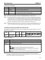
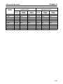
H Changes in Default Settings and Setting Ranges
The defaults and setting ranges for the following parameters have been changed for applications.
D Cumulative Operation Time Display Change (Parameter o2-07)
Previously 0 was display when the default value was set for the cumulative operation time, but this has
been changed to display the current cumulative operation time as the default.
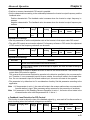
D New Parameter Setting Ranges
Parameter
number
E2-06
E5-06
L2-03
L8-02
1-16
Parameter name
Motor leakage inductance
Motor 2 leakage inductance
Minimum baseblock time
Inverter overheat detection prealarm level
Applicable
Inverters
All Inverters
All Inverters
All Inverters
All Inverters
Previous setting
range
0% to 30%
0% to 30%
0.0 to 5.0 s
50 to 110°C
New setting
range
0% to 40%
0% to 40%
0.1 to 5.0 s
50 to 130°C
Chapter 1
Introduction
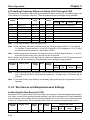
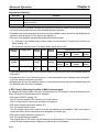
D New Parameter Default Setting
Parameter
number
L2-04
Parameter name
Voltage restart time
Applicable
Inverters
Inverters of
55 kW or larger
Previous setting
New setting
range
range
0.6 s
1.0 s
1-3-4 Software Ver. VSG101114
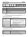
H PG Speed Deviation Detection Function Upgrade (F1-04)
This function has been changed so that the conditions can be selected for speed deviation (DEV) detection. Either of the following two conditions can be selected by means of an F1-04 parameter setting.
D Detect only when the frequency reference matches the output frequency (within the range set in
L4-02).
D Detect only when the frequency reference matches the PG feedback speed (within the range set
in L4-02).
1-17
2
Chapter 2
Installation
2-1
2-2
Mounting
Wiring
Chapter 2
Installation
2-1
Mounting
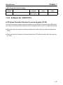
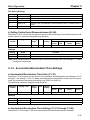
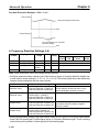
2-1-1 Dimensions
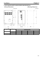
H 3G3FV-A2004/-A2007/-A2015/-A2022/-A2037
3G3FV-A4004/-A4007/-A4015/-A4022/-A4037
D External Dimensions
D Mounting Dimensions
Two, 5.5 dia.
Voltage
g class
Four, M5
Dimensions (mm)
Model 3G3FV-
D
200-V
400-V
2-2
A2004/A2007/A2015
A2022/A2037
A4004/A4007
A4015/A4022/A4037
160
180
160
180
Chapter 2
Installation
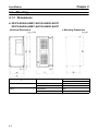
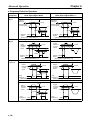
H 3G3FV-A2055/-A2075/-A4055/-A4075
D External Dimensions
D Mounting Dimensions
Two, 7 dia.
Four, M6
H 3G3FV-A2110/-A2150/-A4110/-A4150
D External Dimensions
D Mounting Dimensions
Four, M6
20 (see note)
Two, 7 dia.
Note *The dashed lines apply only to the A2150.
2-3
Chapter 2
Installation
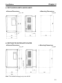
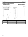
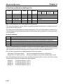
H 3G3FV-B2185/-B2220/-B4185/-B4220/-B4300/-B4450
D External Dimensions
D Mounting Dimensions
Four, M6
Voltage
g class
Model 3G3FVH
200-V
400-V
2-4
B2185/B2220
B4185/B4220
B4300/B4370/B4450
450
450
625
Dimensions (mm)
H1
435
174.5
435
174.5
610
175
D1
Chapter 2
Installation
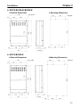
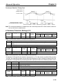
H 3G3FV-B2300/-B2370/-B2450/-B2550/-B4550/-B4750-E
D External Dimensions
D Mounting Dimensions
Two, 12 dia.
Voltage
g class
Four, M10
Model 3G3FVW
200-V
400-V
B2300B2370
B2450/B2550
B4550/B4750-E
425
475
455
675
800
820
Dimensions (mm)
H
W1
320
370
350
H1
650
775
795
2-5
Chapter 2
Installation
H 3G3FV-B2750-E/-B411K-E/-B416K-E
D External Dimensions
D Mounting Dimensions
Two, 14 dia.
Four, M12
Voltage
g class
200-V
400-V
2-6
Model 3G3FVB2750-E
B411K-E
B416K-E
D
400 max.
375 max.
400 max.
Dimensions (mm)
D2
158
130
158
W2
695
695
695
Chapter 2
Installation
H 3G3FV-B418K-E/-B422K-E
D External Dimensions
D Mounting Dimensions
Six, 14 dia.
Six, M12
H 3G3FV-B430K-E
D External Dimensions
D Mounting Dimensions
Six, 14 dia.
Six, M12
2-7
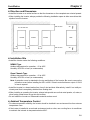
Chapter 2
Installation
Two, 4 dia.
Panel face
125
16
39
Panel cutout
(for cables)
8
8
Front side of panel
4
27
Back side of panel
18.8
30 min.
2-1-2 Installation Conditions
H Cautions and Warnings
!
WARNING
Provide an appropriate stopping device on the machine side to secure safety. (A
holding brake is not a stopping device for securing safety.) Not doing so may result in
injury.
!
WARNING
Provide an external emergency stopping device that allows an instantaneous stop of
operation and power interruption. Not doing so may result in injury.
! Caution
Be sure to install the product in the correct direction and provide specified clearances between the Inverter and control panel or with other devices. Not doing so
may result in fire or malfunction.
! Caution
Do not allow foreign objects to enter inside the product. Doing so may result in fire or
malfunction.
! Caution
Do not apply any strong impact. Doing so may result in damage to the product or
malfunction.
2-8
Chapter 2
Installation
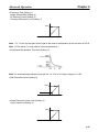
H Direction and Dimensions
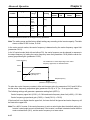
• Install the Inverter on a vertical surface so that the characters on the nameplate are oriented upward.
• When installing the Inverter, always provide the following installation space to allow normal heat dissipation from the Inverter.
120 mm min.
W = 30 mm min.
Inverter
W
Inverter
W
Side
Inverter
W
Air
120 mm min.
Air
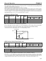
H Installation Site
• Install the Inverter under the following conditions.
NEMA1 Type
Ambient temperature for operation: –10 to 40°C
Humidity: 90% RH or less (no condensation)
Open Chassis Type
Ambient temperature for operation: –10 to 45°C
Humidity: 90% RH or less (no condensation)
Note A protection cover is attached to the top and bottom of the Inverter. Be sure to remove the
protection covers before installing the 200- or 400-V Class Inverter that has an output of 15 kW
or less to a panel.
• Install the Inverter in a clean location free from oil mist and dust. Alternatively, install it in a totally enclosed panel that is completely shielded from floating dust.
• When installing or operating the Inverter, always take special care so that metal powder, oil, water, or
other foreign matter does not get into the Inverter.
• Do not install the Inverter on inflammable material such as wood.
H Ambient Temperature Control
• To enhance operation reliability, the Inverter should be installed in an environment free from extreme
temperature rises.
• If the Inverter is installed in an enclosed environment such as a box, use a cooling fan or air conditioner
to maintain the internal air temperature below 45°C.
2-9
Installation
Chapter 2
H Protecting Inverter from Foreign Matter During Installation
• Place a cover over the Inverter during installation to shield it from metal power produced by drilling.
• Upon completion of installation, always remove the cover from the Inverter. Otherwise, ventilation will
be affected, causing the Inverter to overheat.
2-10
Chapter 2
Installation
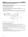
2-2
Wiring
H Cautions and Warnings
!
WARNING
Wiring must be performed only after confirming that the power supply has been
turned OFF. Not doing so may result in electrical shock.
!
WARNING
Wiring must be performed by authorized personnel. Not doing so may result in
electrical shock or fire.
!
WARNING
Be sure to confirm operation only after wiring the emergency stop circuit. Not doing
so may result in injury.
!
WARNING
Always connect the ground terminals to a ground of 100 Ω or less for the 200-V AC
class, or 10 Ω or less for the 400-V AC class. Not connecting to a proper ground may
result in electrical shock.
! Caution
Install external breakers and take other safety measures against short-circuiting in
external wiring. Not doing so may result in fire.
! Caution
Confirm that the rated input voltage of the Inverter is the same as the AC power supply voltage. An incorrect power supply may result in fire, injury, or malfunction.
! Caution
Connect the Braking Resistor and Braking Resistor Unit as specified in the manual.
Not doing so may result in fire.
! Caution
Be sure to wire correctly and securely. Not doing so may result in injury or damage to
the product.
! Caution
Be sure to firmly tighten the screws on the terminal block. Not doing so may result in
fire, injury, or damage to the product.
! Caution
Do not connect an AC power to the U, V, or W output. Doing so may result in damage
to the product or malfunction.
2-11
Installation
Chapter 2
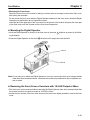
2-2-1 Removing and Mounting the Front Cover
Remove the front cover to wire the terminals. Remove the Digital Operator from the front
cover before removing the front cover. For models of 15 kW or less (both 200-V and
400-V class), do not remove or mount the front cover without first removing the Digital
Operator; otherwise the Digital Operator may malfunction due to imperfect contact.
H Removing the Cover (Models of 15 kW or Less)
• Removing the Digital Operator
Press the lever on the side of the Digital Operator in the arrow 1 direction to unlock the Digital Operator and lift the Digital Operator in the arrow 2 direction to remove the Digital Operator as shown in the
following illustration.
• Removing the Front Cover
Press the left and right sides of the front cover in the arrow 1 directions and lift the bottom of the cover
in the arrow 2 direction to remove the front cover as shown in the following illustration.
2-12
Chapter 2
Installation
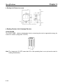
• Mounting the Front Cover
Mount the front cover to the Inverter by taking in reverse order to the steps to remove the front cover
after wiring the terminals.
Do not mount the front cover with the Digital Operator attached to the front cover, otherwise Digital
Operator may malfunction due to imperfect contact.
Insert the tab of the upper part of the front cover into the groove of the Inverter and press the lower part
of the front cover onto the Inverter until the front cover snaps shut.
H Mounting the Digital Operator
• Hook the Digital Operator on clicks A of the front cover in the arrow 1 direction as shown in the following illustration.
• Press the Digital Operator in the arrow 2 direction until it snaps shut with clicks B.
Clicks A
Clicks B
Note Do not remove or attach the Digital Operator or mount or remove the front cover using methods
other than those mentioned above, otherwise the Inverter may malfunction due to imperfect contact or break.
H Removing the Front Cover of Inverters with 18.5-kW Output or More
• The front cover can be removed without removing the Digital Operator from the Inverter provided that
the Inverter model is one with an output of 18.5 kW or more.
• Loosen the four screws of the front cover and move the front cover slightly upwards to remove the front
cover.
2-13
Chapter 2
Installation
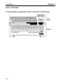
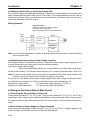
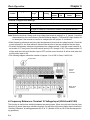
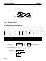
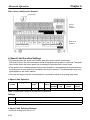
2-2-2 Terminals
H Terminal Block Configuration (200-V Class with 0.4-kW Output)
Control
circuit
terminals
Main circuit
terminals
Power input
2-14
Braking Resistor
Motor output
Chapter 2
Installation
H Main Circuit Terminals
D 200-V Class
A2004 to A2075
0.4 to 7.5 kW
Model 3G3FVMaximum
applied motor
capacity
L1 (R)
L2 (S)
L3 (T)
T1 (U)
T2 (V)
T3 (W)
B1
B2
A2110 to A2150
11 to 15 kW
B2185 to B2220
18.5 to 22 kW
Power supply
y input terminals,, 3-phase,, 200 to 230 VAC,, 50/60 Hz
Motor output terminals,, 3-phase,, 200 to 230 VAC ((correspond to input voltage)
g )
Braking
g Resistor Unit --connection
i terminals
i l
DC reactor
connection terminal
( + 1- + 2)
DC reactor
connection terminal
( + 1- + 2)
DC power supply
input terminal
( + 1- – )
DC power supply
input
in
ut terminal
( + 1- – )
DC power supply
input
in
ut terminal
( + 1- – )
Braking Unit
connection terminal
( + 3- – )
+ 3
---
Braking
a gU
Unitt
connection terminal
( + 3- – )
s
r
s200
s400
---
+ 1
+ 2
–
B2300 to B2750-E
30 to 75 kW
Cooling
g fan power
l iinput terminal
i l
supply
---
Braking Unit
connection terminal
( + 3- – )
See note 1
See note 2
--Ground the terminal at a resistance of less than 100 Ω.
Note 1. Don’t connect a DC power supply. Otherwise, equipment trouble may occur.
Note 2. These are the cooling fan power supply and control circuit power supply input terminals.
2-15
Chapter 2
Installation
D 400-V Class
Model 3G3FV-
A4004 to A4150
B4185 to B4450
B4550 to B416K-E
Maximum
applied motor
capacity
0.4 to 15 kW
18.5 to 45 kW
55 to 160 kW
B418K-E to
B430K-E
185 to 300 kW
Power supply
y input terminals,, 3-phase,, 380 to 460 VAC,, 50/60 Hz
L1 (R)
L2 (S)
L3 (T)
T1 (U)
T2 (V)
T3 (W)
B1
B2
Motor output terminals,, 3-phase,, 380 to 460 VAC ((correspond to input voltage)
g )
Braking
g Resistor Unit --connection
i terminals
i l
+ 1
DC reactor
connection terminal
( + 1- + 2)
DC power supply
input terminal
( + 1- – )
+ 2
–
DC power supply
input terminal
( + 1- – )
Braking Unit
connection terminal
( + 3- – )
+ 3
--Cooling
g fan power
supply
l iinput terminal
i l
s
r
s200
s400
---
DC power supply
input terminal
( + 1- – )
---
Braking Unit
connection terminal
( + 3- – )
See note 1
Braking Unit
connection terminal
( + 3- – )
See note 1
--See notes 2,, 3
--See notes 2,, 3
--Ground the terminal at a resistance of less than 10 Ω.
Note 1. Don’t connect a DC power supply. Otherwise, equipment trouble may occur.
Note 2. These are the cooling fan power supply and control circuit power supply input terminals.
Note 3. When 200-V is used, input 200 to 230 VAC from r – s200. When 400-V is used, input 380 to
460 VAC from r – s400.
H Control Circuit Terminals for All 3G3FV Models
Symbol
Input
1
2-16
Name
Function
2
3
4
5
Forward/Stop
Reverse/Stop
Multi-function contact input 1
Multi-function contact input 2
Multi-function contact input 3
Forward at ON. Stops at OFF.
Reverse at ON. Stops at OFF.
Set by parameter H1-01 (external fault a).
Set by parameter H1-02 (fault reset).
Set by parameter H1-03 (multi-step reference 1).
6
Multi-function contact input 4
Set by parameter H1-04 (multi-step reference 2).
7
Multi-function contact input 5
Set by parameter H1-05 (jog frequency reference)
8
Multi-function contact input 6
Set by parameter H1-06 (external baseblock N.O.)
11
Sequence input common
Common for 1 to 8.
Signal level
Photocoupler
VDC 8 mA
A
24 VDC,
Chapter 2
Installation
Symbol
Input
15
Name
Function
15-VDC power supply for frequency reference.
33
Frequency reference power supply
(–15 VDC)
–15-VDC power supply for frequency refer- –15 VDC
ence.
(±10%), 20 mA
max.
13
Frequency reference input (voltage)
Frequency reference voltage input terminal
Either 0 to +10 V or 0 to ±10 V can be selected as the parameter (H3-01).
Output
Output
Signal level
Frequency reference power supply
(15 VDC)
14
Frequency reference input (current)
Current input terminal for frequency reference.
16
Multi-function analog input
Set by parameter H3-05.
17
12
Frequency reference input common
Shielded wire connection ground
Common for analog input signal.
Shielded terminal for sequence input, frequency reference input.
9
Multi-function contact output
Set by parameter H2-01 (during running).
10
Multi-function contact output common
25
Multi-function output 1
Set by parameter H2-02 (zero speed
detection).
26
Multi-function output 2
Set by parameter H2-03 (agree output reference detection).
27
18
Multi-function output 1 and 2 common
Fault output (NO condition)
Common for terminals, 25, 26.
When fault occurs:
19
Fault output (NC condition)
Terminals 18 to 20: Closed
Terminals 19 to 20: Open
20
Fault output common
21
Multi-function analog output 1
Set by parameter H4-01. (Output frequency: 0 to ±10 V/±100% frequency)
23
Multi-function analog output 2
Set by parameter H4-01. (Output current:
5 V/Inverter rated current)
22
Multi-function analog output common
Common for analog output.
15 VDC
(±10%), 20 mA
max.
0 to 10 VDC (Input impedance:
20 kΩ)
0 to ±10 V (Input impedance:
20 kΩ)
4 to 20 mA (Input impedance:
250 kΩ)
0 to 10 VDC (Input impedance:
20 kΩ)
0 to ±10 V (Input impedance:
20 kΩ)
----Contact output
(SPST-NO)
30 VDC, 1 A
max.
250 VAC, 1 A
max.
Open collector
output
V 50 mA
A
48 V,
max.
Contact output
(SPDT)
30 VDC, 1 A
max.
250 VAC, 1 A
max.
0 to ±10 VDC
((±5%),
), 0 to
10 VDC (±5%),
(±5%)
2 mA max.
Note The settings shown in parentheses in the “Function” column for multi-function inputs 1 to 6, multifunction contact outputs, and multi-function outputs 1 and 2 indicate default settings.
2-17
Chapter 2
Installation
2-2-3 Standard Connection Diagram
H Main Circuit Terminal Connections
D 3G3FV-A2004 to A2075, A4004 to A4150
DC reactor (optional)
Braking Resistor Unit (optional)
L1 (R)
T1 (U)
L2 (S)
T2 (V)
L3 (T)
T3 (W)
3-phase 200 VAC
(400 VAC)
Note: Be sure to remove the short bar before connecting a DC reactor.
D 3G3FV-A2110 to A2150
Braking Resistor Unit (optional)
DC reactor (optional)
Braking Unit (optional)
L1 (R)
T1 (U)
L2 (S)
T2 (V)
L3 (T)
T3 (W)
3-phase VAC
(200 VAC)
Note: Be sure to remove the short bar before connecting a DC reactor.
2-18
Chapter 2
Installation
D 3G3FV-B2185 to B2220, B4185 to B4450
Braking Resistor Unit (optional)
Braking Unit (optional)
3-phase 200 VAC
(400 VAC)
L1 (R)
T1 (U)
L2 (S)
T2 (V)
L3 (T)
T3 (W)
(See note 2)
Note: The DC reactor is built in.
D 3G3FV-B2300 to B2550
Braking Resistor Unit (optional)
Braking Unit (optional)
3-phase 200 VAC
L1 (R)
T1 (U)
L2 (S)
T2 (V)
L3 (T)
T3 (W)
(See note 1)
(See note 2)
Note: The DC reactor is built in.
Note 1. For 200-V class, 30 to 75 kW (B2300 to B2750-E) and 400-V class, 55 to 300 kW (B4550 to
B430K), input the control circuit power supply from r–s. (For others, create the control power
supply internally from the main circuit DC power supply.)
Note 2. The r–L1 (R) and s–L2 (S) terminals are short-circuited for shipping.
2-19
Chapter 2
Installation
D 3G3FV-B2750-E
Braking Resistor Unit (optional)
Braking Unit (optional)
3-phase 200 VAC
(400 VAC)
L1 (R)
L2 (S)
T1 (U)
L3 (t)
T3 (W)
T2 (V)
r (See note 1)
s (See note 2)
Note: The DC reactor is built in.
Note 1. For 200-V class, 30 to 75 kW (B2300 to B2750-E) and 400-V class, 55 to 300 kW (B4550-E to
B430K-E), input the control circuit power supply from r–s. (For others, create the control power supply internally from the main circuit DC power supply.)
Note 2. The r–L1 (R) and s–L2 (S) terminals are short-circuited for shipping.
D 3G3FV-B4550 to B416K-E
Braking Resistor Unit (optional)
Braking Unit (optional)
L1 (R)
3-phase 400 VAC
L2 (S)
T1 (U)
L3 (T)
T2 (V)
(See note 1) T3 (W)
(See note 2)
Note: The DC reactor is built in.
Note 1. For 200-V class, 30 to 75 kW (B2300 to B2750-E) and 400-V class, 55 to 300 kW (B4550-E to
B430K-E), input the control circuit power supply from r–s. (For others, create the control power supply internally from the main circuit DC power supply.)
Note 2. The r–L1 (R) and s (s400)–L2 (S) terminals are short-circuited for shipping.
2-20
Chapter 2
Installation
D 3G3FV-B418K-E to B430K-E
Braking Resistor Unit (optional)
Braking Unit (optional)
3-phase 200 VAC
(400 VAC)
L1 (R)
L2 (S)
T1 (U)
L3 (t)
T3 (W)
T2 (V)
r (See note 1)
s200
s400 (See note 2)
Note: Models of 185 to 300 kW can not use the DC reactor.
Note 1. For 200-V class, 30 to 75 kW (B2300 to B2750-E) and 400-V class, 55 to 300 kW (B4550-E to
B430K-E), input the control circuit power supply from r–s. (For others, create the control power supply internally from the main circuit DC power supply.)
Note 2. The r–L1 (R) and s (s400)–L2 (S) terminals are short-circuited for shipping.
2-21
Chapter 2
Installation
H Control Circuit Terminal Connections (All Models)
Forward/stop
Fault output (NO)
Reverse/stop
Fault output (NC)
Multi-function contact input 1
Fault output common
Multi-function contact input 2
Multi-function contact input 3
Multi-function contact output
Multi-function contact input 4
Multi-function contact
output common
Multi-function contact input 5
Multi-function contact input 6
Multi-function output 1
Sequence input common
Multi-function output 2
Frequency reference power supply +15 V
Multi-function output
common
Frequency reference power supply –15 V
Multi-function analog output 1
Frequency reference input (voltage)
Frequency reference input (current)
Voltmeter
Multi-function
analog output 2
Voltmeter
Multi-function analog input
Frequency reference input common
Multi-function analog
output common
Note Variable resistors for frequency references must be 2 kΩ, 1/4 W min.
Wiring Example
Stop switch
(NC)
Run switch
(NO)
Run command
(Operates when the run switch is closed.)
Stop command
(Stops when the stop switch is open.)
11
Forward/Reverse command
(Multi-function input)
Sequential input common
Note Wiring methods for 3G3FV--CUE (-CE) Inverters are sometimes different. Always check wiring
methods in the Installation Manual (I530 and I520).
2-22
Installation
Chapter 2
2-2-4 Wiring Around the Main Circuit
System reliability and noise resistance are affected by the wiring method used. Therefore, always follow the instructions given below when connecting the Inverter to peripheral devices and other parts.
H Wire Size and Round Solderless Terminal
For the main circuit and ground, always use 600-V polyvinyl chloride (PVC) cables.
If the cable is long and may cause voltage drops, increase the wire size according to the cable length.
2-23
Chapter 2
Installation
D Wire Sizes
Voltage class
200-V Class
2-24
Model
Terminal
Terminal
screw
3G3FV-A2004
L1, L2, L3, (–), (+)1, (+)2, B1, B2, T1, T2, T3 M4
Wire
thickness
(mm2)
2 to 5.5
3G3FV-A2007
L1, L2, L3, (–), (+)1, (+)2, B1, B2, T1, T2, T3 M4
2 to 5.5
3G3FV-A2015
L1, L2, L3, (–), (+)1, (+)2, B1, B2, T1, T2, T3 M4
2 to 5.5
3.5 to 5.5
3G3FV-A2022
L1, L2, L3, (–), (+)1, (+)2, B1, B2, T1, T2, T3 M4
3.5 to 5.5
3G3FV-A2037
L1, L2, L3, (–), (+)1, (+)2, B1, B2, T1, T2, T3 M4
5.5
3G3FV-A2055
L1, L2, L3, (–), (+)1, (+)2, B1, B2, T1, T2, T3 M5
8
5.5 to 8
3G3FV-A2075
L1, L2, L3, (–), (+)1, (+)2, B1, B2, T1, T2, T3 M5
8
5.5 to 8
3G3FV-A2110
L1, L2, L3, (–), (+)1, (+)2, (+)3, T1, T2, T3
M6
22
8
3G3FV-A2150
L1, L2, L3, (–), (+)1, (+)2, (+)3, T1, T2, T3
M8
M6
30
8
3G3FV-B2185
L1, L2, L3, (–), (+)1, (+)2, (+)3, T1, T2, T3
M8
30
14
3G3FV-B2220
r, s
L1, L2, L3, (–), (+)1, (+)2, (+)3, T1, T2, T3
M4
M8
0.5 to 5.5
38
14
3G3FV-B2300
r, s
L1, L2, L3, (–), (+)3, T1, T2, T3
M4
M10
M8
0.5 to 5.5
100
22
3G3FV-B2370
r, s
L1, L2, L3, (–), (+)3, T1, T2, T3
M4
M10
M8
0.5 to 5.5
60 x 2P
22
3G3FV-B2450
r, s
L1, L2, L3, (–), (+)3, T1, T2, T3
M4
M10
M8
0.5 to 5.5
60 x 2P
22
3G3FV-B2550
r, s
L1, L2, L3, (–), (+)3, T1, T2, T3
M4
M10
M8
0.5 to 5.5
60 x 2P
30
r, s
M4
0.5 to 5.5
Chapter 2
Installation
Voltage class
200-V Class
Model
3G3FV-B2750-E
Terminal
Terminal
screw
L1, L2, L3, (–), (+)3, T1, T2, T3
M12
M8
Wire
thickness
(mm2)
100 x 2P
50
r, s
M4
0.5 to 5.5
Terminal
screw
Note The wire thickness is set for copper wires at 75°C.
Voltage class
400-V Class
Model
Terminal
3G3FV-A4004
L1, L2, L3, (–), (+)1, (+)2, B1, B2, T1, T2, T3 M4
Wire
thickness
(mm2)
2 to 5.5
3G3FV-A4007
L1, L2, L3, (–), (+)1, (+)2, B1, B2, T1, T2, T3 M4
2 to 5.5
3G3FV-A4015
L1, L2, L3, (–), (+)1, (+)2, B1, B2, T1, T2, T3 M4
2 to 5.5
3G3FV-A4022
L1, L2, L3, (–), (+)1, (+)2, B1, B2, T1, T2, T3 M4
2 to 5.5
3G3FV-A4037
L1, L2, L3, (–), (+)1, (+)2, B1, B2, T1, T2, T3 M4
2 to 5.5
3.5 to 5.5
3G3FV-A4055
L1, L2, L3, (–), (+)1, (+)2, B1, B2, T1, T2, T3 M4
3.5 to 5.5
3G3FV-A4075
L1, L2, L3, (–), (+)1, (+)2, B1, B2, T1, T2, T3 M5
5.5
3G3FV-A4110
L1, L2, L3, (–), (+)1, (+)2, B1, B2, T1, T2, T3 M5
M6
8 to 14
8
3G3FV-A4150
L1, L2, L3, (–), (+)1, (+)2, B1, B2, T1, T2, T3 M5
M6
8 to 14
8
3G3FV-B4185
L1, L2, L3, (–), (+)1, (+)2, (+)3, T1, T2, T3
M6
M8
14
8
3G3FV-B4220
r, s
L1, L2, L3, (–), (+)1, (+)2, (+)3, T1, T2, T3
M4
M6
M8
0.5 to 5.5
22
8
3G3FV-B4300
r, s
L1, L2, L3, (–), (+)1, (+)2, (+)3, T1, T2, T3
M4
M8
0.5 to 5.5
22
8
3G3FV-B4370
r, s
L1, L2, L3, (–), (+)1, (+)2, (+)3, T1, T2, T3
M4
M8
0.5 to 5.5
30
14
r, s
M4
0.5 to 5.5
2-25
Chapter 2
Installation
Voltage class
400-V Class
Model
Terminal
Wire
thickness
(mm2)
50
14
3G3FV-B4450
L1, L2, L3, (–), (+)1, (+)2, (+)3, T1, T2, T3
M8
3G3FV-B4550
r, s
L1, L2, L3, (–), (+)3, T1, T2, T3
M4
M10
M8
0.5 to 5.5
100
22
3G3FV-B4750-E
r, s200, s400
L1, L2, L3, (–), (+)3, T1, T2, T3
M4
M10
M8
0.5 to 5.5
60 x 2P
22
3G3FV-B411K-E
r, s200, s400
L1, L2, L3, (–), (+)3, T1, T2, T3
M4
M10
M8
0.5 to 5.5
60 x 2P
30
3G3FV-B416K-E
r, s200, s400
L1, L2, L3, (–), (+)3, T1, T2, T3
M4
M12
M8
0.5 to 5.5
100 x 2P
50
3G3FV-B418K-E
r, s200, s400
L1, L2, L3, (–), (+)1, (+)3, T1, T2, T3
M4
M16
M8
0.5 to 5.5
325 x 2P
50
3G3FV-B422K-E
r, s200, s400
L1, L2, L3, (–), (+)1, (+)3, T1, T2, T3
M4
M16
M8
0.5 to 5.5
325 x 2P
60
3G3FV-B430K-E
r, s200, s400
L1, L2, L3, (–), (+)1, (+)3, T1, T2, T3
M4
M16
M8
0.5 to 5.5
325 x 2P
60
r, s200, s400
M4
0.5 to 5.5
Note The wire thickness is set for copper wires at 75°C.
2-26
Terminal
screw
Chapter 2
Installation
D Round Solderless Terminals and Tightening Torque
Wire thickness
(mm2)
0.5
0.75
1.25
2
3.5/5.5
8
14
22
30/38
50/60
80
100
100
150
200
325
Terminal
screw
M4
M4
M4
M4
M5
M6
M8
M4
M5
M6
M8
M5
M6
M8
M6
M8
M6
M8
M8
M8
M10
M10
M12
M12 x 2
M16
Size
1.25-4
1.25-4
1.25-4
2-4
2-5
2-6
2-8
5.5-4
5.5-5
5.5-6
5.5-8
8-5
8-6
8-8
14-6
14-8
22-6
22-8
38-8
60-8
60-10
80-10
100-10
100-12
15012
200-12
325-12
325-16
Tightening
torque (NSm)
1.2
1.2
1.2
1.2
2.0
2.5
6.0
1.2
2.0
2.5
6.0
2.0
2.5
6.0
2.5
6.0
2.5
6.0
6.0
6.0
10.0
10.0
10.0
14.0
14.0
14.0
14.0
25.0
Note Determining Wire Size
Determine the wire size for the main circuit so that line voltage drop is within 2% of the rated voltage.
Line voltage drop is calculated as follows:
3 x wire resistance (Ω/km) x wire length (m) x current (A) x 10–3
Line voltage drop (V)
2-27
Chapter 2
Installation
H Wiring on the Input Side of the Main Circuit
D Installing a Molded-case Circuit Breaker
Always connect the power input terminals (R/L1, S/L2, and T/L3) and power supply via a molded case
circuit breaker (MCCB) suitable to the Inverter.
• Install one wiring circuit breaker per Inverter.
• Choose an MCCB with a capacity of 1.5 to 2 times the Inverter’s rated current.
• For the MCCB’s time characteristics, be sure to consider the Inverter’s overload protection (one minute at 150% of the rated output current).
• If the MCCB is to be used in common among multiple Inverters, or other devices, set up a sequence
such that the power supply will be turned OFF by a fault output, as shown in the following diagram.
Inverter
3-phase/
Single-phase
200 V AC
3-phase
400 V AC
Power
supply
(See note.)
19
Fault output (NC)
20
Note Use a 400/200 V transformer for a 400-V model.
D Installing a Ground Fault Interrupter
Inverter outputs use high-speed switching, so high-frequency leakage current is generated.
In general, a leakage current of approximately 100 mA will occur for each Inverter (when the power
cable is 1 m) and approximately 5 mA for each additional meter of power cable.
Therefore, at the power supply input area, use a special-purpose breaker for Inverters, which detects
only the leakage current in the frequency range that is hazardous to humans and excludes high-frequency leakage current.
• For the special-purpose breaker for Inverters, choose a ground fault interrupter with a sensitivity
amperage of at least 10 mA per Inverter.
• When using a general leakage breaker, choose a ground fault interrupter with a sensitivity amperage
of 200 mA or more per Inverter and with an operating time of 0.1 s or more.
2-28
Installation
Chapter 2
D Installing a Magnetic Contactor
If the power supply of the main circuit is to be shut off because of the sequence, a magnetic contactor
can be used instead of a molded-case circuit breaker.
When a magnetic contactor is installed on the primary side of the main circuit to stop a load forcibly,
however, the regenerative braking does not work and the load coasts to a stop.
• A load can be started and stopped by opening and closing the magnetic contactor on the primary side.
Frequently opening and closing the magnetic contactor, however, may cause the Inverter to break
down. To maintain the service life of the Inverter’s internal relays and electrolytic capacitors, it is recommended that this operation be performed no more than once every 30 minutes.
• When the Inverter is operated with the Digital Operator, automatic operation cannot be performed
after recovery from a power interruption.
• When using the Braking Resistor Unit, be sure to arrange a sequence in which the thermal relay of the
Unit turns the magnetic contactor OFF.
D Connecting Input Power Supply to the Terminal Block
Input power supply can be connected to any terminal on the terminal block because the phase
sequence of input power supply is irrelevant to the phase sequence (R/L1, S/L2, and T/L3).
D Installing an AC Reactor
If the Inverter is connected to a large-capacity power transformer (660 kW or more) or the phase
advance capacitor is switched, an excessive peak current may flow through the input power circuit,
causing the converter unit to break down.
To prevent this, install an optional AC reactor on the input side of the Inverter.
This also improves the power factor on the power supply side.
D Installing a Surge Absorber
Always use a surge absorber or diode for the inductive loads near the Inverter. These inductive loads
include magnetic contactors, electromagnetic relays, solenoid valves, solenoid, and magnetic brakes.
2-29
Chapter 2
Installation
D Installing a Noise Filter on the Power Supply Side
The Inverter’s outputs utilize high-speed switching, so noise may be transmitted from the Inverter to the
power line and adversely affect other devices in the vicinity. It is recommended that a Noise Filter be
installed at the Power Supply to minimize this noise transmission. Conversely, noise can also be reduced from the power line to the Inverter.
Wiring Example 1
Input Noise Filters
Simple Input Noise Filter: 3G3EV-PLNFD
Input Noise Filter: 3G3IV-PFN
EMC-conforming Input Noise Filter: 3G3FV-PFS
Power
supply
3G3FV
Noise
Filter
SYSDRIVE
SYSMAC or
other control
device
Note Use a noise filter designed for Inverters. A general-purpose noise filter will be less effective and
may not reduce noise.
D Calculating the Inverter Input Power Supply Capacity
The following formula can generally be used to calculate the input power supply capacity for the
Inverter. Always select an Inverter with more than sufficient capacity.
Input power supply capacity [kVA] =
Motor output [kW]/(Motor efficiency x Inverter efficiency x Inverter input power factor)
Normal motor efficiency = 0.8, Normal inverter efficiency = 0.9, Inverter input power factor = 0.65 to 0.9
Note The Inverter’s input power factor will vary with the impedance of the power supply facilities. Use
0.9 when using an AC reactor and 0.65 when not using an AC reactor.
For the input current, divide the input power supply capacity by the input voltage. Assuming the Inverter’s resistance to overloads to be 150%, the calculated value can be multiplied by 1.5.
Example for 3-phase 200 V:
1.5 x input power supply capacity/(p3 x 200 V)
Example for single-phase 200 V:
1.5 x input power supply capacity/200 V
H Wiring on the Output Side of Main Circuit
D Connecting the Terminal Block to the Load
Connect output terminals T1 (U), T2 (V), and T3 (W) to motor lead wires T1 (U), T2 (V), and T3 (W),
respectively. Check that the motor rotates forward with the forward command. Switch over any two of
the output terminals to each other and reconnect if the motor rotates in reverse with the forward command.
D Never Connect a Power Supply to Output Terminals
Never connect a power supply to output terminals T1 (U), T2 (V), and T3 (W). If voltage is applied to the
output terminals, the internal circuit of the Inverter will be damaged.
2-30
Chapter 2
Installation
D Never Short or Ground Output Terminals
If the output terminals are touched with bare hands or the output wires come into contact with the Inverter casing, an electric shock or grounding will occur. This is extremely hazardous. Also, be careful not to
short the output wires.
D Do Not Use a Phase Advancing Capacitor or Noise Filter
Never to connect a phase advance capacitor or LC/RC noise filter to the output circuit. Doing so may
result in damage to the Inverter or cause other parts to burn.
D Do Not Use an Electromagnetic Switch or Magnetic Contactor
Do not connect an electromagnetic switch or magnetic contactor to the output circuit. If a load is connected to the Inverter during running, an inrush current will actuate the overcurrent protective circuit in
the Inverter.
D Installing a Thermal Relay
This Inverter has an electronic thermal protection function to protect the motor from overheating. If,
however, more than one motor is operated with one Inverter or multi-polar motor is used, always install a
thermal relay (THR) between the Inverter and the motor and set n033 to 0 (no thermal protection).
In this case, program the sequence so that the magnetic contactor on the input side of the main circuit is
turned off by the contact of the thermal relay.
D Installing a Noise Filter on Output Side
Connect a noise filter to the output side of the Inverter to reduce radio noise and induction noise.
3G3FV
Power
supply
Noise filter
SYSDRIVE
Signal line
Induction
noise
Controller
Radio noise
AM radio
Induction Noise: Electromagnetic induction generates noise on the signal line, causing the controller
to malfunction.
Radio Noise:
Electromagnetic waves from the Inverter and cables cause the broadcasting radio
receiver to make noise.
2-31
Chapter 2
Installation
D Countermeasures Against Induction Noise
As described previously, a noise filter can be used to prevent induction noise from being generated on
the output side. Alternatively, cables can be routed through a grounded metal pipe to prevent induction
noise. Keeping the metal pipe at least 30 cm away from the signal line considerably reduces induction
noise.
Power
supply
Metal pipe
3G3FV
SYSDRIVE
30 cm min.
Signal line
Controller
D Countermeasures Against Radio Interference
Radio noise is generated from the Inverter as well as the input and output lines. To reduce radio noise,
install noise filters on both input and output sides, and also install the Inverter in a totally enclosed steel
box. The cable between the Inverter and the motor should be as short as possible.
Steel box
Power
supply
3G3FV
Noise
filter
SYSDRIVE
Metal pipe
Noise
filter
D Cable Length between Inverter and Motor
As the cable length between the Inverter and the motor is increased, the floating capacity between the
Inverter outputs and the ground is increased proportionally. The increase in floating capacity at the Inverter outputs causes the high-frequency leakage current to increase, and this may adversely affect
peripheral devices and the current detector in the Inverter’s output section. To prevent this from occurring, use a cable of no more than 100 meters between the Inverter and the motor. If the cable must be
longer than 100 meters, take measures to reduce the floating capacity by not wiring in metallic ducts, by
using a separate cable for each phase, and so on.
Also adjust the carrier frequency according to the cable length between the Inverter and the motor, as
shown in the table below.
Cable length
Carrier frequency
(Set value: C06-01)
(Set value: C06-02)
(Set value: C06-02)
2-32
50 m max.
15 kHz max.
(15.0)
(15.0)
(0)
100 m max.
10 kHz max.
(10.0)
(10.0)
(0)
More than 100 m
5 kHz max.
(5.0)
(5.0)
(0)
Installation
Chapter 2
Note The carrier frequency setting range varies depending on the Inverter capacity.
200-V class, 18.5 kW max.; 400-V class, 30 kW max.: 0.4 to 15.0 kHz
200-V class, 22 to 75 kW; 400-V class, 37 to 160 kW: 0.4 to 10.0 kHz
400-V class, 185 to 300 kW:
0.4 to 2.5 kHz
D Single-phase Motors Cannot Be Used
The Inverter is not suited for the variable speed control of single-phase motors.
Single-phase motors are either capacitor start motors or split-phase start motors. (The method for determining rotation direction at startup is different.) If a capacitor start motor is used, the capacitor may be
damaged by a sudden electric discharge caused by Inverter output. If a split-phase start motor is used,
the starting coil may burn because the centrifugal switch does not operate.
H Ground Wiring
• Always use the ground terminal of the 200-V Inverter with a ground resistance of less than 100 Ω and
that of the 400-V Inverter with a ground resistance of less than 10 Ω.
• Do not share the ground wire with other devices such as welding machines or power tools.
• Always use a ground wire that complies with technical standards on electrical equipment and minimize the length of the ground wire.
Leakage current flows through the Inverter. Therefore, if the distance between the ground electrode
and the ground terminal is too long, potential on the ground terminal of the Inverter will become unstable.
• When using more than one Inverter, be careful not to loop the ground wire.
2-33
Chapter 2
Installation
H Countermeasures against Harmonics
With the continuing development of electronics, the generation of harmonics from industrial machines
has been causing problems recently. Refer to the following for the definition of harmonics (i.e., harmonic
currents with voltages) and countermeasures against the generation of harmonics from the Inverter.
D Harmonics (Harmonic Currents with Voltages)
• Definition
Harmonics consist of electric power produced from AC power and alternating at frequencies that are
integral multiples of the frequency of the AC power.
The following are the harmonic frequencies of a 60- or 50-Hz commercial power supply.
Second harmonic:
120 (100) Hz
Third harmonic:
180 (150) Hz
Second harmonic (120 Hz)
Basic frequency
(60 Hz)
Third harmonic (180 Hz)
• Problems Caused by Harmonics Generation
The waveform of the commercial power supply will be distorted if the commercial power supply contains excessive harmonics.
Machines with such a commercial power supply will malfunction or generate excessive heat.
Basic frequency (60 Hz)
Third harmonic (180 Hz)
Distorted current
waveform
D Causes of Harmonics Generation
• Usually, electric machines have built-in circuitry that converts commercial AC power supply into DC
power. Such AC power, however, contains harmonics due to the difference in current flow between AC
and DC.
• Obtaining DC from AC using Rectifiers and Capacitors
DC voltage is obtained by converting AC voltage into a pulsating one-side voltage with rectifiers and
smoothing the pulsating one-side voltage with capacitors. Such AC current, however, contains harmonics.
2-34
Chapter 2
Installation
• Inverter
The Inverter as well as normal electric machines has an input current containing harmonics because
the Inverter converts AC into DC.
The output current of the Inverter is comparatively high. Therefore, the ratio of harmonics in the output
current of the Inverter is higher than that of any other electric machine.
Voltage
Time
Rectified
Voltage
Time
Smoothed
Voltage
Time
Current
A current flows into the capacitors. The
current is different from the voltage in
waveform.
Time
D Countermeasures with Reactors against Harmonics Generation
• DC/AC Reactors
The DC reactor and AC reactor suppress harmonics and currents that change suddenly and greatly.
The DC reactor suppresses harmonics better than the AC reactor. The DC reactor used with the AC
reactor suppresses harmonics more effectively.
The input power factor of the Inverter is improved by suppressing the harmonics in the input current of
the Inverter.
Note 18.5- to 160-kW Inverters have a built-in DC reactor.
185- to 300-kW Inverters cannot use a DC reactor.
• Connection
Connect the DC reactor to the internal DC power supply of the Inverter after shutting off the power
supply to the Inverter and making sure that the charge indicator of the Inverter turns off.
!
WARNING
Do not touch the internal circuitry of the Inverter in operation, otherwise an electric
shock or a burn injury may occur.
2-35
Chapter 2
Installation
• Wiring Method
With DC Reactor
DC reactor
(optional)
200 VAC (400 V)
L1 (R)
T1 (U)
L2 (S)
T2 (V)
L3 (T)
T3 (W)
3G3FV
Note Be sure to remove the short bar on terminals +1 and +2 before connecting the DC reactor.
With DC and AC Reactors
DC reactor
(optional)
200 VAC (400 V)
L1 (R)
AC reactor
(optional)
T1 (U)
L2 (S)
T2 (V)
L3 (T)
T3 (W)
3G3FV
Note Be sure to remove the short bar on terminals +1 and +2 before connecting the DC reactor.
• Reactor Effects
Harmonics are effectively suppressed when the DC reactor is used with the AC reactor as shown in
the following table.
Harmonic supprespp
sion
i
method
h d
No reactor
AC reactor
DC reactor
DC and AC reactors
2-36
Harmonic generation rate (%)
5th harmonic
65
38
30
28
7th har11th
monic harmonic
41
8.5
14.5
7.4
13
8.4
9.1
7.2
13th
harmonic
7.7
3.4
5
4.1
17th
harmonic
4.3
3.2
4.7
3.2
19th
harmonic
3.1
1.9
3.2
2.4
23th
harmonic
2.6
1.7
3.0
1.6
25th
harmonic
1.8
1.3
2.2
1.4
Chapter 2
Installation
H Connecting the Braking Resistor
• Connect the braking resistor as shown in the following diagram.
• When using a Braking Resistor Unit, set L8-01 to “1” (i.e., overheating protection of the braking resistor) and set L3-04 to “0” (i.e., no decelerating stall prevention) or “2” (i.e., braking with stall prevention).
Inverter
! Caution
Braking resistor
The braking resistor’s connection terminals are B1 and B2. Do not connect any other
terminals. Connecting any terminals other than B1 or B2 can cause the resistor to
overheat, resulting in damage to the equipment.
H Connecting the Braking Resistor Unit and Braking Unit
• Connect the Braking Resistor Unit and Braking Unit to the Inverter as shown in the following diagrams.
• Set L8-01 to “0” (i.e., no overheating protection of the braking resistor) and L3-04 to “0” (i.e., no decelerating stall prevention) or “2” (i.e., braking with stall prevention) before using the Inverter with the
Braking Resistor Unit connected.
Note 1. Set L8-01 to “1” before operating the Inverter with the braking resistor without thermal relay
trip contacts.
Note 2. The Braking Resistor Unit cannot be used and the deceleration time cannot be shortened by
the Inverter if L3-04 is set to “1” (i.e., decelerating stall prevention).
• To prevent the Unit from overheating, make a power supply sequence as shown below or connect the
thermal relay trip output of the Unit to the external fault input terminal of the Inverter to interrupt the
running of the Inverter.
D 200-V Class with 0.4- to 7.5-kW Output and 400-V Class with 0.4- to 15-kW Output
Braking Resistor Unit
Inverter
Thermal relay
trip contact
2-37
Chapter 2
Installation
D 200-V Class with 11-kW-or-more Output and 400-V Class with 18.5-or-more Output
Braking Resistor Unit
Braking Unit
Thermal relay
trip contact
Inverter
N
Thermal relay trip contact
D Connecting Braking Units in Parallel
When connecting two or more Braking Units in parallel, use the wiring and connectors shown in the
following diagram. There are connectors for selecting whether each Braking Unit is to be a Master or
Slave. Select “Master” for the first Braking Unit only; select “Slave” for all other Braking Units (i.e., from
the second Unit onwards).
Inverter
Thermal
relay trip
contact
Thermal
relay trip
contact
Thermal
relay trip
contact
Braking
Resistor
Unit
Braking
Resistor
Unit
Braking
Resistor
Unit
Braking Unit #2
Braking Unit #1
Thermal
relay trip
contact
2-38
Braking Unit #3
Thermal
relay trip
contact
Thermal
relay trip
contact
Chapter 2
Installation
D Power Supply Sequence
200-V class:
400-V class:
Three-phase, 200 to
230 VAC (50/60 Hz)
Three-phase, 380 to
460 VAC (50/60 Hz)
Power
supply
L1 (R)
L2 (S)
L3 (T)
(See note)
Inverter
Note Use a transformer with 200- and 400-V outputs for the power supply of the 400-V Inverter.
2-2-5 Wiring Control Circuit Terminals
A control signal line must be 50 m maximum and separated from power lines. The frequency reference must be input to the Inverter through twisted-pair wires.
H Wire Size and Round Solderless Terminals
Use thick wires to prevent voltage drops if the wires are long.
D Wires for All Inverter Models
Terminal
1 to 11, 13 to 33
Terminal
screw
M3.5
12 (G)
M3.5
Wire thickness (mm2)
Stranded wire: 0.5 to 1.25
Single wire: 0.5 to 1.25
0.5 to 2
Type
Shielded, twisted-pair wire
Shielded,
polyethylene-covered vinyl
polyethylene-covered,
sheath cable
D Round Solderless Terminals for Ground Terminal
Wire thickness
(mm2)
0.5
0.75
1.25
2
Terminal
screw
M3.5
Size
1.25 to 3.5
1.25 to 3.5
1.25 to 3.5
2 to 3.5
Screw torque
(N S m)
0.8
H Considerations When Wiring Control Circuit Terminals
• Wire control signal lines separately from the main circuit lines and other power lines.
• Wire control circuit terminals 9, 10, 18, 19, and 20 (contact outputs) separately from terminals 1 to 8,
21, 22, 23, 25, 26, 27, 33, and 11 to 17.
• Connect shielded wire to terminal 12(G).
• Insulate the shielded areas with tape to prevent contact with other signal lines and equipment.
2-39
Chapter 2
Installation
2-2-6 Installing and Wiring PG Speed Control Cards
PG Speed Control Cards are used for executing speed control using a pulse generator (PG). There are
four types of PG speed control, as shown below. Select the type that fits the application and control
method.
3G3FV-PPGA2: A-phase (single) pulse input for open collector output, special-purpose V/f control
3G3FV-PPGB2: A/B-phase pulse input for open collector output, special-purpose vector control
3G3FV-PPGD2: A-phase (single) pulse input, line driver input, special-purpose V/f control
3G3FV-PPGX2: A/B/Z-phase pulse input, line driver input, special-purpose vector control
H Installing a PG Speed Control Card
1. Turn off the main-circuit power supply, and leave it off for at least one minute before removing the
front cover of the Inverter (or at least three minutes for Inverters of 30 kW or more). Check to be sure
that the CHARGE light is OFF.
2. Insert the spacer (which is provided) into the spacer hole in the Inverter’s mounting base. For Inverters of 3.7 kW or less, there are two adjacent holes. Insert the spacer into the 7CN hole. The spacer
cannot be easily removed if inserted into the wrong hole. Be very careful to insert the spacer into the
correct hole, and in the proper direction.
3. Referring to the enlarged illustration in the following diagram, align the PG Speed Control Card with
the catch position as shown by (1) and (2) and fit it precisely to the Option-A connector. Then pass
the spacer through the spacer hole at the Card. (Refer to illustration A.) Check to be sure that it is
precisely aligned with the 4CN position, and snap it into the proper position.
PG Speed Control Card
Option A mounting spacer
(Accessory: SRNT41028-9)
Spacer mounting hole
Control
board
4CN
Option-A
Connector
Option C
2CN
Option-C
Connector
Inverter mounting base
Inverter mounting base
Spacer mounting hole
PG Speed
Control Card
3CN
Option-D
Connector
Option D
Spacer
Mounting
base side
Option A side
Spacer mounting
Front
2-40
Enlargement
Side
Chapter 2
Installation
H PG Speed Control Card Terminal Blocks
D 3G3FV-PPGA2 (For V/f With PG Feedback Mode Only)
Terminal
TA1
No.
1
2
3
+12-V/open collector switching
terminal
4
Pulse input terminal
5
TA2
Contents
Power supply
y for pulse g
generator
6
7
8
(E)
Pulse motor output terminal
Shielded-wire connection terminal
Specifications
12 VDC (±5%), 200 mA max.
0 VDC (GND for power supply)
Terminal for switching between12-V voltage
input and open collector input.
input For open
collector input, short across 3 and 4.
H: +4 to 12 V; L: +1 V max. (Maximum
response frequency: 30 kHz)
Pulse input common
12 VDC (±10%), 20 mA max.
Pulse monitor output common
---
D 3G3FV-PPGB2 (For Flux Vector Control Mode Only)
Terminal
TA1
No.
1
2
3
A-phase pulse input terminal
4
5
TA2
TA3
Contents
Power supply
y for pulse g
generator
B-phase pulse input terminal
6
1
2
3
4
(E)
A-phase monitor output terminal
B-phase monitor output terminal
Shielded-wire connection terminal
Specifications
12 VDC (±5%), 200 mA max.
0 VDC (GND for power supply)
H: +8 to 12 V; L: +1 V max. (Maximum
response frequency: 30 kHz)
Pulse input common
H: +8 to 12 V; L: +1 V max. (Maximum
response frequency: 30 kHz)
Pulse input common
Open collector output, 24 VDC, 30 mA max.
A-phase monitor output common
Open collector output, 24 VDC, 30 mA max.
B-phase monitor output common
---
D 3G3FV-PPGD2 (For V/f With PG Feedback Mode Only)
Terminal
TA1
TA2
No.
1
2
3
4
5
6
7
8
(E)
Contents
Power supply
y for pulse g
generator
Pulse input + terminal
Pulse input – terminal
Common terminal
Pulse monitor output + terminal
Pulse monitor output – terminal
Shielded-wire connection terminal
Specifications
12 VDC (±5%), 200 mA max. (see note)
0 VDC (GND for power supply)
5 VDC (±5%), 200 mA max. (see note)
Line driver input ((RS-422 level input))
M i
f
kH
Maximum
response frequency:
300 kHz
--Line driver output ((RS-422 level output))
---
Note 5 VDC and 12 VDC cannot be used at the same time.
2-41
Chapter 2
Installation
D 3G3FV-PPGX2 (For Flux Vector Control Mode Only)
Terminal
TA1
TA2
TA3
No.
1
2
3
4
5
6
7
8
9
10
1
2
3
4
5
6
7
(E)
Contents
Power supply
y for pulse g
generator
A-phase + input terminal
A-phase – input terminal
B-phase + input terminal
B-phase – input terminal
Z-phase + input terminal
Z-phase – input terminal
Common terminal
A-phase + output terminal
A-phase – output terminal
B-phase + output terminal
B-phase – output terminal
Z-phase + output terminal
Z-phase – output terminal
Control circuit common
Specifications
12 VDC (±5%), 200 mA max. (see note)
0 VDC (GND for power supply)
5 VDC (±5%), 200 mA max. (see note)
Line driver input ((RS-422 level input))
M i
Maximum
response frequency:
f
300 kHz
kH
0 VDC (GND for power supply)
Line driver output ((RS-422 level output))
Control circuit GND
---
Note 5 VDC and 12 VDC cannot be used at the same time.
2-42
Chapter 2
Installation
H Wiring a PG Speed Control Card
D 3G3FV-PPGA2 (For V/f With PG Feedback Mode Only)
Three-phase,
200 VAC (400 VAC)
3G3FV
L1
E6B2-CWZ3E Encoder
T1
L2
T2
L3
T3
+12-V power supply
0-V power supply
12-V voltage output
(A/B phase)
Pulse 0 V
Pulse monitor output
Three-phase,
200 VAC (400 VAC)
3G3FV
L1
T1
L2
T2
L3
T3
E6B2-CWZ3C Encoder
+12-V power supply
0-V power supply
Open collector output
(A/B phase)
Pulse 0 V
Pulse monitor output
Note 1. Twisted-pair shielded wire must be used for signal lines.
Note 2. Do not use the pulse generator’s power supply for anything other than the pulse generator
(encoder). Using it for another purpose can cause malfunctions due to noise.
Note 3. The length of the pulse generator’s wiring must not be more than 30 meters.
2-43
Chapter 2
Installation
I/O Circuit Configuration
+12 V
PG power
supply +12 V
+12 V
Pulse input
0V
1K
1K
+12 V
+12 V 0 V
Pulse
monitor
output
2K 2K
Pulse input
3K
0V
3.9 K
0V
Note When connecting to a voltage-output-type PG (encoder), select a PG with an output impedance
of no more than 3 kΩ.
D 3G3FV-PPGB2 (For Flux Vector Control Mode Only)
Three-phase 200 VAC
(400 VAC)
Encoder
L1
T1
L2
T2
L3
T3
3G3FV-PPGB2
Power supply +12 V
Power supply 0 V
Power supply +12 V
A-phase pulse output
Power supply +12 V
B-phase pulse output
A-phase pulse
monitor output
B-phase pulse
monitor output
Note 1. Twisted-pair shielded wire must be used for signal lines.
Note 2. Do not use the pulse generator’s power supply for anything other than the pulse generator
(encoder). Using it for another purpose can cause malfunctions due to noise.
Note 3. The length of the pulse generator’s wiring must not be more than 30 meters.
2-44
Chapter 2
Installation
I/O Circuit Configuration
PG power
supply +12 V
+12 V
Division rate circuit
0V
A-phase
pulse input
A-phase pulse
monitor output
A-phase
pulses
B-phase pulse
monitor output
B-phase
pulses
B-phase
pulse input
Forward output pulses
A-phase pulses
B-phase pulses
Note When connecting to a voltage-output-type PG (encoder), select a PG that has an output impedance with a current of at least 12 mA to the input circuit photocoupler (diode). The E6B2-CWZ3E
cannot be used.
D 3G3FV-PPGD2 (For V/f With PG Feedback Mode Only)
Three-phase
200 VAC (400 VAC)
Encoder
L1
T1
L2
T2
L3
T3
3G3FV-PPGD2
Power supply 0 V
Power supply 5 V
Pulse output + (A/B phase)
Pulse output –
(A/B phase)
Pulse monitor output
Note 1. Twisted-pair shielded wire must be used for signal lines.
Note 2. Do not use the pulse generator’s power supply for anything other than the pulse generator
(encoder). Using it for another purpose can cause malfunctions due to noise.
Note 3. The length of the pulse generator’s wiring must not be more than 50 meters.
2-45
Chapter 2
Installation
D 3G3FV-PPGX2 (For Flux Vector Control Mode Only)
Three-phase
200 VAC (400 VAC)
Encoder
L1
T1
L2
T2
L3
T3
3G3FV-PPGX2
Power supply 0 V
Power supply 5 V
A-phase pulse output +
A-phase pulse output –
B-phase pulse output +
B-phase pulse output –
Z-phase pulse output +
Z-phase pulse output –
A-phase pulse monitor
output
B-phase pulse monitor
output
Z-phase pulse monitor
output
Note 1. Shielded, twisted-pair wire must be used for signal lines.
Note 2. Do not use the pulse generator’s power supply for anything other than the pulse generator
(encoder). Using it for another purpose can cause malfunctions due to noise.
Note 3. The length of the pulse generator’s wiring must not be more than 50 meters.
H Wiring PG Speed Control Card Terminal Blocks
Use no more than 30 meters of wiring for PG (encoder) signal lines and no more than 50 meters for
3G3FV-PPGD2 and 3G3FV-PPGX2, and keep them separate from power lines. Use shielded, twistedpair wire for pulse input and pulse output monitor wire, and connect the shield to the shielded wire connection terminal.
D Wires for All Inverter Models
Terminal
Terminal
screw
Pulse generator power supply --Pulse input terminal
Pulse monitor output terminal
Shielded wire connection
terminal
2-46
M3.5
Wire thickness (mm2)
Stranded wire: 0.5 to 1.25
Single wire: 0.5 to 1.25
0.5 to 2
Type
Shielded, twisted-pair wire
Shielded, polyethylene-covered, vinyl sheath cable
Chapter 2
Installation
D Solderless Terminals for Control Circuit Terminals
The use of solderless terminals for the control circuit terminals is recommended because solderless
terminals are easy to connect securely.
d1 dia.
Wire thickness
0.5 mm2
0.75 mm2
1 mm2
1.5 mm2
Model
A1 0.5-8WH
A1 0.75-8GY
A1 1-8RD
A1 1.5-8BK
d1
1.00
1.20
1.40
1.70
d2
2.60
2.80
3.00
3.50
Manufacturer
Phoenix Contact
Note Do not solder
wires with the control circuit terminals if wires are used instead of solderless termid2 dia.
nals. Wires may not contact well with the control circuit terminals or the wires may be disconnected from the control circuit terminals due to vibration if the wires are soldered.
D Round Solderless Terminal Sizes and Screw Torque
Wire thickness (mm2)
0.5
0.75
1.25
2
Terminal screw
M3.5
Size
1.25 to 3.5
1.25 to 3.5
1.25 to 3.5
2 to 3.5
Screw torque (N S m)
0.8
H Wiring Control Circuit Terminals
D Wiring Method
1. Loosen the terminal screws with a thin-slotted screwdriver.
2. Insert the wires from underneath the terminal block.
3. Tighten the terminal screws firmly.
Note 1. Always separate the control signal line from the main circuit cables and other power cables.
Note 2. Do not solder the wires to the control circuit terminals. The wires may not contact well with the
control circuit terminals if the wires are soldered.
Note 3. The end of each wire connected to the control circuit terminals must be stripped for approximately 7 mm.
Note 4. Use a shielded wire for the ground terminal.
Note 5. Insulate the shield with tape so that the shield will not touch any signal line or device.
Thin-slotted screwdriver
Blade of screwdriver
Control circuit
terminal block
Strip the end for 7 mm if
no solderless terminal is
used.
Solderless terminal or
wire without soldering
3.5 mm max.
Blade thickness: 0.6 mm max.
Wires
2-47
Chapter 2
Installation
Note 6. Tighten the screws to a tightening torque of 0.5 to 0.6 Nm. The terminal block may be damaged if the tightening torque is too strong, and malfunctions and short-circuits may result if the
tightening torque is too weak.
H Selecting the Number of PG (Encoder) Pulses
D 3G3FV-PPGA2/-PPGB2
• The maximum response frequency is 30 kHz.
• Taking into consideration the encoder pulse deviation (phase difference: 90 ±45°) and the waveform
when the cable is long, select a smaller number of pulses than the ones shown in the following table.
Motor’s maximum speed (r/min)
Number of encoder pulses (p/r)
Maximum encoder frequency (kHz)
1,800
500
15
1,500
600
15
900
1,00
15
D 3G3FV-PPGD2/-PPGX2
• The maximum response frequency is 300 kHz.
• When the encoder pulse deviation (phase difference: 90 ±45°) is taken into consideration, the number
of encoder pulses can be calculated by means of the following formula:
Number of encoder pulses [p/r] x
60 x maximum response frequency (300,000 Hz)
2 x motor’s maximum rotation speed (r/min)
• If the motor’s maximum speed is less than 4,000 r/min, an encoder of 1,000 to 2,000 p/r is recommended. Even if an encoder with higher than required resolution is selected, it will not improve the
speed control range or precision.
2-48
3
Chapter 3
Preparing for Operation
3-1
3-2
3-3
3-4
3-5
3-6
3-7
3-8
Using the Digital Operator
Modes
Operation Mode
Initialize Mode
Program Mode
Auto-tuning Mode
Modified Constants Mode
Operation Mode Selection Key and
Local/Remote Selection Input
Chapter 3
Preparing for Operation
3-1
Using the Digital Operator
Operation Mode Indicators
DRIVE:
FWD:
REV:
SEQ:
REF:
Lit when in operation mode.
Lit when there is a forward command input.
Lit when there is a reverse command input.
Lit when the forward/reverse command from
the control circuit terminal is enabled.
Lit when the frequency reference from
control circuit terminals 13 and 14 is enabled.
Data Display
Two-line LCD that displays data for monitoring, parameter names, and set values with 16 characters
per line.
Keys
Execute operations such as setting parameters,
monitoring, JOG, and auto-tuning.
Key
Name
Operation Mode
Selection Key
Menu Key
Function
Switches between Operator and parameter setting (run command and
frequency reference). This key can be enabled or disabled with a
parameter setting (o2-02).
Displays each mode.
Escape Key
Returns to the status before the Enter Key is pressed.
Jog Key
Enables JOG operation when the 3G3FV is in operation with the
Digital Operator.
Selects the rotation direction of the motor when the 3G3FV is in
operation with the Digital Operator.
Selects digits for parameter settings. Also acts as the reset key when
an fault has occurred. (See note.)
Selects modes, groups, functions, parameter names, and set values.
This key increases numbers when pressed.
Selects modes, groups, functions, parameter names, and set values.
This key decreases numbers when pressed.
Enters modes, functions, constants, and set values after they are set.
Forward/Reverse
Rotation Selection Key
Reset/Digit Selection
Key
Increment Key
Decrement Key
Enter Key
Run Key
Stop Key
Starts the 3G3FV running when the 3G3FV is in operation with the
Digital Operator.
Stops the 3G3FV running. This key can be enabled or disabled with a
parameter setting (o2-02) in operation with the control circuit terminal.
Note For safety reasons, the Reset Key cannot be used when a run command (forward/reverse) is being input. Turn OFF the run command before attempting to reset.
3-2
Chapter 3
Preparing for Operation
3-2
Modes
This section describes the 3G3FV’s various parameter setting and monitoring modes.
S Inverter Modes
• The SYSDRIVE 3G3FV Inverter’s parameters and monitoring functions have been organized in
groups, so it is easier to make settings and read data. These function groups are known as modes.
• The 3G3FV is equipped with 5 modes, as shown in the following table.
Mode
Operation mode
Initialize mode
Program mode
Auto-tuning
mode
Modified
constants mode
Primary function(s)
The Inverter can be run in this mode.
Use this mode when monitoring values such as frequency references or output
current, displaying fault information, or displaying the fault history.
Use this mode when selecting the language displayed on the Digital Operator,
selecting the access level for setting/reading parameters, selecting the control mode,
or initializing the parameters.
Use this mode when setting/reading the parameters required for operation. The
program-mode functions are subdivided into the following groups:
Application:
Operation mode selection, DC control, speed search, etc.
Tuning:
Acceleration/deceleration times, S-curve characteristics, carrier
frequencies, etc.
Reference:
Settings related to frequency control
Motor:
V/f characteristics and motor parameters
Option:
Settings for Optional Cards
Terminal:
Settings for sequential I/O and analog I/O
Protection:
Settings for the motor and inverter protection functions
Operator:
Selects the Digital Operator’s display and key functions
(Usable only with the vector control mode)
Use this mode when running a motor with unknown motor parameters in the vector
control mode. The motor parameters are calculated and set automatically.
Use this mode to set/read parameters that have been changed from their factory-set
values.
S Switching Modes
• Once the Unit has been put into operation mode by pressing the Menu Key, the Increment and Decrement Keys can be pressed to switch to other modes.
• Press the Enter Key to set/read the parameters in each mode.
3-3
Chapter 3
Preparing for Operation
• Press the Escape Key to return to the mode display from the parameter display.
All modes/parameters status
• Operation mode
** Main Menu **
Operation
• Initialize mode
** Main Menu **
Initialize
• Programming mode
** Main Menu **
Programming
• Auto-tuning mode (see note 1)
** Main Menu **
Auto-Tuning
• Modified constants mode
** Main Menu **
Modified Consts
Power ON
Monitor (Frequency reference value)
Frequency Ref
U1-01= 60.00 HZ
Operator display language selection
Select Language
English
Frequency reference input method
selection (see note 2)
Reference Source
Operator
Auto-tuning (Rated voltage setting)
Rated Voltage
200.0 VAC
Display parameters changed from
factory settings
Reference 1
d1-01= 60.00 HZ
Note 1. Auto-tuning mode will be displayed only when vector control mode has been selected. (The
factory setting is for open-loop vector control.)
Note 2. The actual display depends on the parameter access level setting (A1-01).
3-4
Chapter 3
Preparing for Operation
S Parameter Access Level
The SYSDRIVE 3G3FV’s has three access levels which divide the various parameters based on their
usage, as shown below. The access level restricts which parameters can be set or displayed.
Level
Quick-start
Basic
Advanced
Function
Allows setting/reading of parameters required for test runs. (factory-set)
Allows setting/reading of general-purpose parameters.
Allows setting/reading of all parameters.
Set the access level in initialize mode with parameter A1-01.
H Changing the Access Level from Quick-start to Basic
Key sequence
Display
** Main Menu **
Operation
** Main Menu **
Initialize
Select Language
English
Access Level
Quick Start
A1-01=
2 ***
Quick Start
A1-01=
3
Basic Level
Entry Accepted
Access Level
Basic Level
Explanation
Displays operation mode.
Displays initialize mode.
Puts the Unit in initialize mode.
Switches to the access level parameter.
Displays the access level parameter setting.
Changes the access level setting to “BASIC.”
Writes the new parameter setting.
Returns to the access level parameter display.
3-5
Chapter 3
Preparing for Operation
The following diagram shows this procedure in flowchart format.
** Main Menu **
Operation
** Main Menu **
Initialize
Select Language
English
Access Level
Quick Start
A1-01=
2 ***
Quick-Start
A1-01=
3
Basic Level
Access Level
Basic Level
Entry Accepted
S Setting Parameters in Each Access Level
• The displays in program mode differ for each access level. (There is no difference in other modes.)
• This section provides the procedure to change the acceleration time to 20 s in each access level. The
acceleration time (C1-01) is a parameter in program mode.
• If the new parameter setting is not written to the Unit (by pressing the Enter Key) within one minute
after starting the procedure, the display will automatically revert to the original parameter setting. In
this case, the procedure must be started again.
3-6
Chapter 3
Preparing for Operation
H Parameter Setting Levels (Partial)
MENU
Operation mode
Initialize mode
Program mode
Application
b1 Sequence
b1-01 Reference source
b1-02 Run source
Parameter to be changed
[Mode]
b1-03 Stopping method
Tuning
C1 Accel/Decel
C1-01 Accel Time 1
Reference
C2 S-Curve Acc/Dec
C1-02 Decel Time 1
[Group]
[Function]
[Parameter]
H Setting the Parameter in the Quick-start Access Level
The parameter level will be displayed when the Enter Key is pressed at the program mode display.
Key sequence
2 times
2 times
---
Display
** Main Menu **
Operation
** Main Menu **
Programming
Reference Source
Terminals
Run Source
Terminals
Stopping Method
Ramp to Stop
Accel Time 1
c1-01=
10.0 Sec
Accel Time 1
0010.0 Sec
Accel Time 1
0010.0 Sec
Accel Time 1
0020.0 Sec
Entry Accepted
Accel Time 1
c1-01=
20.0 Sec
** Main Menu **
Programming
Explanation
Displays operation mode.
Displays program mode.
Puts the Unit in program mode.
Displays the b1-01 Reference source selection.
Displays the b1-02 Run source selection.
Displays the b1-03 Stopping method selection.
Displays C1-01 Acceleration time 1.
Selects the parameter so that the leading 0 flashes.
(The digit that can be changed flashes.)
Moves the cursor so that the “1” digit flashes.
Changes the 1 to a 2.
Writes the new setting.
Returns to the C1-01 Acceleration time 1 display.
Returns to the program mode display.
3-7
Chapter 3
Preparing for Operation
H Setting the Parameter in the Basic Access Level
The function level will be displayed when the Enter Key is pressed at the program mode display.
Key sequence
2 times
2 times
---
3-8
Display
** Main Menu **
Operation
** Main Menu **
Programming
Function b1
Sequence
Function b2
DC Braking
Function C1
Accel/Decel
Accel Time 1
c1-01=
10.0 Sec
Accel Time 1
0010.0 Sec
Accel Time 1
0010.0 Sec
Accel Time 1
0020.0 Sec
Entry Accepted
Accel Time 1
c1-01=
20.0 Sec
Function C1
Accel/Decel
Explanation
Displays operation mode.
Displays program mode.
Puts the Unit in program mode.
Displays the b1 Sequence function selection.
Displays the b2 DC Braking function selection.
Displays the C1 Accel/Decel function selection.
Displays C1-01 Acceleration time 1.
Selects the parameter so that the leading 0 flashes.
(The digit that can be changed flashes.)
Moves the cursor so that the “1” digit flashes.
Changes the 1 to a 2.
Writes the new setting.
Returns to the C1-01 Acceleration time 1 display.
Returns to the program mode display.
Chapter 3
Preparing for Operation
H Setting the Parameter in the Advanced Access Level
The group level will be displayed when the Enter Key is pressed at the program mode display.
Key sequence
2 times
2 times
---
Display
** Main Menu **
Operation
** Main Menu **
Programming
Group b
Application
Group C
Tuning
Function C1
Accel/Decel
Accel Time 1
c1-01=
10.0 Sec
Accel Time 1
0010.0 Sec
Accel Time 1
0010.0 Sec
Accel Time 1
0020.0 Sec
Entry Accepted
Accel Time 1
c1-01=
20.0 Sec
Function C1
Accel/Decel
Explanation
Displays operation mode.
Displays program mode.
Puts the Unit in program mode.
Displays the Group b Application group selection.
Displays the Group C Tuning group selection.
Displays the C1 Accel/Decel function selection.
Displays C1-01 Acceleration time 1.
Selects the parameter so that the leading 0 flashes.
(The digit that can be changed flashes.)
Moves the cursor so that the “1” digit flashes.
Changes the 1 to a 2.
Writes the new setting.
Returns to the C1-01 Acceleration time 1 display.
Returns to the C1 Accel/Decel function selection.
3-9
Preparing for Operation
3-3
Chapter 3
Operation Mode
Operation mode is the mode in which the Inverter can run. When running the Inverter,
press the Enter Key from the operation mode display to bring up the monitor display. Run
commands can’t be received from any other display. Once the Unit is running, it can be
switched to other modes.
Many parameters can’t be changed when the Inverter is running. Refer to Chapter 7
Parameter Lists for details.
Bring up monitor displays such as the frequency reference, output frequency, output
current, and output voltage as well as fault information and the fault history in operation
mode.
3-10
Chapter 3
Preparing for Operation
S Operations in Operation Mode
All modes/parameters status
Operation mode
** Main Menu **
Operation
Power ON
Frequency reference setting/display
Frequency Ref
U1-01= 0.00 HZ
Output frequency display
Output Freq
U1-02= 0.00 HZ
Output current display
Output Current
U1-03=
0.00 A
Output voltage display
Output Voltage
U1-06=
0.0 VAC
Function selection U2 (fault trace)
Function U2
Fault Trace
Function selection U3
(fault history)
Function U3
Fault History
Function selection U1 (Monitor)
Function U1
Monitor
Contents of fault trace
Contents of fault history
Various monitors
3-11
Chapter 3
Preparing for Operation
S Conditions for Monitoring
The following tables show the items that can be monitored in operation mode. The table’s “Valid access
levels” column indicates whether an item can be monitored in a particular access level and control
mode. The codes in this column have the following meanings.
Q: These items can be monitored in all access levels. (Quick-start, Basic, and Advanced)
B: These items can be monitored in the Basic and Advanced access levels.
A: These items can be monitored in the Advanced access level only.
X: These items cannot be monitored in the control mode shown.
The output signal levels for multi-function analog outputs shown in the table are for a gain of 100.0 and a
bias of 0.00.
Status Monitor
Item
e
U1-01
U1-02
Display
sp ay
Frequency Ref
Output Freq
Function
u c o
Ou pu s
Output
signal
g a
l
levels
l for
f
multi-function
analog outputs
Monitors/sets the frequency reference
value.
10 V:
Max. frequency
The display units can be set with parameter o1-01.
(0 to ±10 V possible)
Monitors the output frequency.
10 V:
Max. frequency
The display units can be set with parameter o1-01.
Valid access levels
Min.
Units
U
it
V/f
V/f
w/PG
Open
Vector
Flux
Vector
0.01
Hz
Q
Q
Q
Q
0.01
Hz
Q
Q
Q
Q
0.1 A
Q
Q
Q
Q
(0 to ±10 V possible)
U1-03
Output Current
Monitors the output current.
10 V: Rated current
U1-04
Control Method
Shows which control mode is set.
Can’t be output.
---
Q
Q
Q
Q
U1-05
Motor Speed
Monitors the motor speed.
10 V:
Max. frequency
0.01
Hz
X
Q
Q
Q
0.1 V
Q
Q
Q
Q
1V
Q
Q
Q
Q
0.1
kW
Q
Q
Q
Q
0.1%
X
X
Q
Q
---
Q
Q
Q
Q
(0 to +10 V output)
(0 to ±10 V possible)
U1-06
U1-07
Output Voltage
DC Bus Voltage
Monitors the Inverter’s internal output
voltage reference value.
10 V: 200 (400) VAC
Monitors the DC voltage of the Inverter’s
internal main circuit.
10 V: 400 (800) VDC
10 V:
Max. motor capacity
(0 to +10 V output)
(0 to +10 V output)
U1-08
Output kWatts
Monitors the output power. (This is an internally detected value.)
U1-09
Torque Reference
Monitors the internal torque reference
value when vector control is used.
10 V: Rated torque
U1-10
Input Term Sts
Shows the ON/OFF status of inputs.
Can’t be output.
(Input terminal
status)
U1-10=00000000
(0 to ±10 V possible)
3-12
1: Terminal 1 ON
1: Terminal 2 ON
1: Terminal 3 ON
1: Terminal 4 ON
1: Terminal 5 ON
1: Terminal 6 ON
1: Terminal 7 ON
1: Terminal 8 ON
(0 to ±10 V possible)
Chapter 3
Preparing for Operation
Item
U1-11
U1-12
U1-13
Display
Function
Output Term Sts
Shows the ON/OFF status of outputs.
(Output terminal
status)
U1-11=00000000
Int Ctl Sts 1
Shows the Inverter’s operating status.
(Internal control
status)
U1-12=00000000
Elapsed Time
Monitors the Inverter’s elapsed operating
time.
Output signal
levels for
multi-function
analog outputs
Min.
Units
Valid access levels
V/f
V/f
w/PG
Open
Vector
Flux
Vector
Can’t be output.
---
Q
Q
Q
Q
Can’t be output.
---
Q
Q
Q
Q
Can’t be output.
1 hr
Q
Q
Q
Q
1: Terminals 9–10 ON
1: Terminal 25 ON
1: Terminal 26 ON
Not used. (always 0)
1: Terminals 18/19–20
ON
1: Running
1: Zero-speed level
1: Reverse
1: Reset input ON
1: F.ref/F.out agree
1: Inverter ready
1: Minor fault detected
1: Major fault detected
The initial value and running/power-on
time selection can be set with parameters
o2-07 and o2-08.
U1-14
FLASH ID
Manufacturer’s ID number
Can’t be output.
---
Q
Q
Q
Q
U1-15
Term 13 Level
Monitors the input voltage of the frequency reference (voltage).
10 V: 100% (10 V)
0.1%
B
B
B
B
0.1%
B
B
B
B
0.1%
B
B
B
B
0.1%
B
B
B
B
0.1%
X
X
B
B
0.01
Hz
A
A
A
A
0.01
%
X
A
X
A
0.01
%
X
A
X
A
0.01
%
X
A
X
A
0.01
%
A
A
A
A
(Terminal 13 input
voltage level)
U1-16
Term 14 Level
(Terminal 14 input
current level)
U1-17
Term 16 Level
(Terminal 16 input
voltage level)
U1-18
U1-19
U1-20
Mot SEC Current
Mot EXC Current
SFS Output
(0 to ±10 V possible)
An input of 10 V corresponds to 100%.
Monitors the input current of the frequency reference (current).
10 V: 100% (20 mA)
(0 to +10 V output)
An input of 20 mA corresponds to 100%.
Monitors the input voltage of the multifunction analog input.
10 V: 100% (10 V)
(0 to ±10 V possible)
An input of 10 V corresponds to 100%.
Monitors the calculated value of the motor’s secondary current (Iq). The motor’s
rated current corresponds to 100%.
10 V: Rated current
Monitors the calculated value of the motor’s excitation current (Id). The motor’s
rated current corresponds to 100%.
10 V: Rated current
Monitors the output frequency after a soft
start. The display shows the frequency
without the correction from compensation
functions such as slip compensation.
10 V:
Max. frequency
(0 to +10 V output)
(0 to +10 V output)
(0 to ±10 V possible)
U1-21
ASR Input
Monitors the input to the speed control
loop. The max. frequency corresponds to
100%.
10 V:
Max. frequency
U1-22
ASR Output
Monitors the output from the speed control loop. The motor’s rated current corresponds to 100%.
10 V: Rated current
Monitors the speed deviation within the
speed control loop. The max. frequency
corresponds to 100%.
10 V:
Max. frequency
Monitors the feedback value when PID
control is used. The input for the max.
frequency corresponds to 100%.
10 V:
Max. frequency
U1-23
U1-24
Speed Deviation
PID Feedback
(0 to ±10 V possible)
(0 to ±10 V possible)
(0 to ±10 V possible)
(0 to ±10 V possible)
3-13
Chapter 3
Preparing for Operation
Item
U1-25
Display
DI-16 Reference
Function
Monitors the reference value from a
3G3FV-PDI16H2 Digital Command Card.
Output signal
levels for
multi-function
analog outputs
Min.
Units
Valid access levels
V/f
V/f
w/PG
Open
Vector
Flux
Vector
Can’t be output.
---
A
A
A
A
Monitors the Inverter’s internal voltage
reference value for the motor’s secondary current control.
10 V: 200 (400) VAC
0.1 V
X
X
A
A
Monitors the Inverter’s internal voltage
reference value for the motor’s excitation
current control.
10 V: 200 (400) VAC
0.1 V
X
X
A
A
The value will be displayed in binary or
BCD depending on parameter F3-01.
U1-26
U1-27
Voltage Ref (Vq)
Voltage Ref (Vd)
(0 to ±10 V possible)
(0 to ±10 V possible)
U1-28
CPU ID
Manufacturer’s CPU software ID number
Can’t be output.
0.1 V
A
A
A
A
U1-32
ACR(q) Output
Monitor’s the current control output value
for the motor’s secondary current.
10 V: 100%
0.1%
X
X
A
A
U1-33
ACR(d) Output
Monitor’s the current control output value
for the motor’s excitation current.
10 V: 100%
0.1%
X
X
A
A
U1-34
OPE Detected
Displays the first constant number for
which an OPE error was detected.
Can’t be output.
---
A
A
A
A
U1-35
Zero Servo Pulse
Multiplies the number of PG pulses by
four to display the movement width at the
zero servo stop point.
Can’t be output.
1
X
X
X
A
U1-36
PID Input
PID reference + PID reference bias – PID
feedback value
The max. frequency corresponds to
100%.
10 V:
Max. frequency
0.01
%
A
A
A
A
U1-37
PID Output
PID control output
The max. frequency corresponds to
100%.
10 V:
Max. frequency
0.01
%
A
A
A
A
U1-38
PID Setpoint
PID reference + PID reference bias
The max. frequency corresponds to
100%.
10 V:
Max. frequency
0.01
%
A
A
A
A
3-14
Chapter 3
Preparing for Operation
Fault Trace
Item
e
Display
sp ay
Function
u c o
Ou pu s
Output
signal
g a
l
levels
l for
f
multi-function
analog outputs
Min.
Units
U
it
Can’t be ou
Ca
output.
u
Valid access levels
V/f
V/f
w/PG
Open
Vector
Flux
Vector
U2-01
Current Fault
Information on the current fault
---
Q
Q
Q
Q
U2-02
Last Fault
Information on the last fault
---
Q
Q
Q
Q
U2-03
Frequency Ref
Frequency reference value when the “last
fault” occurred.
0.01
Hz
Q
Q
Q
Q
U2-04
Output Freq
Output frequency when the “last fault” occurred.
0.01
Hz
Q
Q
Q
Q
U2-05
Output Current
Output current when the “last fault” occurred.
0.1 A
Q
Q
Q
Q
U2-06
Motor Speed
Motor speed when the “last fault” occurred.
0.01
Hz
X
Q
Q
Q
U2-07
Output Voltage
Output voltage when the “last fault” occurred.
0.1 V
Q
Q
Q
Q
U2-08
DC Bus Voltage
The main circuit DC voltage when the “last
fault” occurred.
1V
Q
Q
Q
Q
U2-09
Output kWatts
Output power when the “last fault” occurred.
0.1
kW
Q
Q
Q
Q
U2-10
Torque Reference
Torque reference when the “last fault” occurred. (The rated torque = 100%.)
0.1%
X
X
Q
Q
U2-11
Input Term Sts
Input terminal status when the “last fault” occurred. (Same format as U1-10.)
---
Q
Q
Q
Q
U2-12
Output Term Sts
Output terminal status when the “last fault”
occurred. (Same format as U1-11.)
---
Q
Q
Q
Q
U2-13
Inverter status
Inverter operating status when the “last fault”
occurred. (Same format as U1-12.)
---
Q
Q
Q
Q
U2-14
Elapsed time
Elapsed operating or power-on time when the
“last fault” occurred.
1 hr
Q
Q
Q
Q
Fault History
Item
e
Display
sp ay
Function
u c o
Ou pu s
Output
signal
g a
l
levels
l for
f
multi-function
analog outputs
Min.
Units
U
it
Can’t be output.
Ca
ou u
Valid access levels
V/f
V/f
w/PG
Open
Vector
Flux
Vector
U3-01
Last Fault
Information on the last fault.
---
Q
Q
Q
Q
U3-02
Fault Message 2
Information on the 2nd to last fault.
---
Q
Q
Q
Q
U3-03
Fault Message 3
Information on the 3rd to last fault.
---
Q
Q
Q
Q
U3-04
Fault Message 4
Information on the 4th to last fault.
---
Q
Q
Q
Q
U3-05
Elapsed Time 1
Elapsed running or power-on time when the
last fault occurred.
1 hr
Q
Q
Q
Q
U3-06
Elapsed Time 2
Elapsed running or power-on time when the
2nd to last fault occurred.
1 hr
Q
Q
Q
Q
U3-07
Elapsed Time 3
Elapsed running or power-on time when the
3rd to last fault occurred.
1 hr
Q
Q
Q
Q
U3-08
Elapsed Time 4
Elapsed running or power-on time when the
4th to last fault occurred.
1 hr
Q
Q
Q
Q
3-15
Chapter 3
Preparing for Operation
S Monitoring at Startup
• In operation mode, the frequency reference, output frequency, output current, and output voltage can
be monitored immediately if the default settings are being used. One of these four values, the output
voltage, can be changed to a different value. When a value other than the output voltage is to be monitored, set that value’s number in parameter o1-01 (user monitor selection).
• When the power is turned on, the frequency reference will appear in the Unit’s data display if the default settings are being used. Any one of the four values monitored at startup (frequency reference,
output frequency, output current, or the value set in parameter o1-01) can be selected to appear when
the power is turned on. The value that appears at startup is determined by parameter o1-02 (PowerOn Monitor).
• Parameters o1-01 and o1-02 can be changed in the Basic or Advanced access levels. These parameters can be changed during operation.
User Monitor Selection (Parameter o1-01)
Use parameter o1-01 to select the values that will be monitored at startup.
Use the last two digits from the “U1 Monitor” list (U1-) to select a value. For example, the torque
reference is U1-09, so input 9 to select the torque reference.
Parameter
number
o1-01
Display
p y name
User Monitor Sel
Setting
g
range
Units
4 to 28
---
Default
setting
6
Valid access levels
V/f
V/f with
Control
PG
Basic or Advanced
Open Loop
Vector
Flux
Vector
The following example shows how to change parameter o1-01 so that the output power is monitored at
startup instead of the output voltage.
Key sequence
2 times
2 times
Display
** Main Menu **
Operation
** Main Menu **
Programming
Function b1
Sequence
Function o1
Monitor Select
User Monitor Sel
Output Voltage
o1-01=
6 ***
Output Voltage
o1-01=
8 ***
Output kWatts
Entry Accepted
User Monitor Sel
Output kWatts
Explanation
Displays operation mode.
Displays program mode.
Puts the Unit in program mode.
Displays function selection o1.
Puts the Unit in function selection o1. (Monitor Select)
Displays the parameter setting for o1-01.
Sets the parameter to output power.
Writes the new setting.
Returns to the Monitor Select display.
Note In this example, the setting is changed in the Basic access level.
Power-On Monitor (Parameter o1-02)
Use parameter o1-02 to indicate which value will be displayed when the Unit is started.
A setting of 1 indicates the frequency reference, 2 indicates the output frequency, 3 indicates the output
current, and 4 indicates the value set in parameter o1-01.
3-16
Chapter 3
Preparing for Operation
Parameter
number
o1-02
Display
p y name
Power-On
Monitor
Setting
g
range
Units
1 to 4
---
Default
setting
1
Valid access levels
V/f
V/f with
Control
PG
Basic or Advanced
Open Loop
Vector
Flux
Vector
The following example shows how to change parameter o1-02 so that the output current is displayed at
startup. (The procedure continues from the end of the previous example.)
Key sequence
2 times
Display
User Monitor Sel
Output kWatts
Power-On Monitor
Frequency Ref
o1-02=
1 ***
Frequency Ref
O1-02=
3
Output Current
Entry Accepted
Power-On Monitor
Output Current
Function o1
Monitor Select
** Main Menu **
Programming
Explanation
Monitor Select display (See the previous example.)
Displays the Power-On Monitor display.
Displays the parameter setting for o1-02.
Sets the parameter to output current.
Writes the new setting.
Returns to the Power-On Monitor display.
Returns to the function selection o1 display.
Returns to the program mode display.
Note In this example, the setting is changed in the Basic access level.
3-17
Chapter 3
Preparing for Operation
3-4
Initialize Mode
The initialize mode is used to select the language displayed by the Unit, the access level,
and the control mode; it is also used to initialize the Unit’s parameters.
S Selecting the Display Language
Use parameter A1-00 to select the language displayed by the Unit. Messages can be displayed in 0:
English, 1: Japanese, 2: German, 3: French, 4: Italian, 5: Spanish, or 6: Portuguese. This parameter is
not initialized by the initialize operation and it can be changed during operation.
Note The language that is set will be indicated on the display.
Parameter
number
A1-00
Display
p y name
Select Language
Setting
g
range
Units
0 to 6
---
Default
setting
0
Valid access levels
V/f
V/f with Open Loop
Control
PG
Vector
Quick-start, Basic, or Advanced
Flux
Vector
Example
The following example shows how to change parameter A1-00 so that Japanese is displayed instead of
English.
Key sequence
Display
** Main Menu **
Operation
** Main Menu **
Initialize
Select Language
English
A1-00=
0
English
A1-00=
1 ***
FN]:^
<^.3=3 67:P6]
Explanation
Displays operation mode.
Displays initialize mode.
Puts the Unit in initialize mode.
(Select Language display)
Displays the parameter setting for A1-00.
Sets the display language to Japanese.
Writes the new setting.
9^]:^ >]@8
FN]:^
Returns to the Select Language display.
S Setting the Access Level
Use parameter A1-01 to select the parameter access level. This level determines which parameters
can be displayed and changed. (The parameters which can be displayed and changed also depend
upon the control mode being used.) This parameter can be changed during operation.
Parameter
number
A1-01
3-18
Display
p y name
Access Level
Setting
g
range
Units
0 to 4
---
Default
setting
2
Valid access levels
V/f
V/f with Open Loop
Control
PG
Vector
Quick-start, Basic, or Advanced
Flux
Vector
Chapter 3
Preparing for Operation
Access Level Settings
Setting
0
1
2
3
4
Name
Function
Operation Only This setting allows operation mode and initialize mode to be displayed or
changed. Use this setting to prevent parameter settings from being changed.
User Level
This setting allows only the user-selected parameters (up to 32) to be displayed
or changed. Select the desired parameters as “User Parameters” in parameters
A2-01 through A2-32.
Quick-start
This setting allows the parameters required to start the Inverter (about 25) to be
displayed or changed.
Basic
This setting allows the commonly used parameters to be displayed or changed.
Advanced
This setting allows all parameters to be displayed or changed.
S Setting the Control Mode
Use parameter A1-02 to select one of the four control modes. This parameter is not initialized by the
initialize operation and it cannot be changed during operation.
Parameter
number
A1-02
Display
p y name
Control Method
Setting
g
range
Units
0 to 3
---
Default
setting
2
Valid access levels
V/f
V/f with Open Loop
Control
PG
Vector
Quick-start, Basic, or Advanced
Flux
Vector
Control Mode Settings
Setting
0
1
2
3
Name
Function
V/f Control
V/f control without pulse generator (normal V/f control)
V/f w/PG Fdbk
V/f control with pulse generator (V/f control using a PG Speed Control Card)
Open Loop Vector Vector control without pulse generator
(Vector control using the Inverter’s internal speed information)
Flux Vector
Vector control with pulse generator
(Vector control using a PG Speed Control Card)
Control Mode Characteristics
Characteristic
Basic control method
V/f Control
Voltage/frequency
control (open loop)
Speed detector
Not required
Optional Speed
Detectors
Speed control range
Starting torque
Speed control
precision
Torque limit
Torque control
Example applications
Not required
1:40
150%/3 Hz
±2 to 3%
Not possible
Not possible
• Multiple motors
V/f w/PG Fdbk
Voltage/frequency
control with speed
compensation
Required
(pulse generator)
3G3FV-PPGA2 or
3G3FV-PPGD2
1:40
150%/3 Hz
±0.03%
Open Loop Vector
Flux Vector
Current vector con- Current vector control without PG
trol with PG
1:100
150%/1 Hz
±0.2%
Required
(pulse generator)
3G3FV-PPGB2 or
3G3FV-PPGX2
1:1,000
150%/0 Hz
±0.02%
Not possible
Not possible
• Simple speed
feedback control
Possible
Not possible
• Variable speed
drive applications
Possible
Possible
• Simple servo
drives
Not required
Not required
• Precision speed
control
• Torque control
3-19
Chapter 3
Preparing for Operation
Example
The following example shows how to change parameter A1-02 to select Flux Vector control (vector control with pulse generator).
Key sequence
2 times
Display
** Main Menu **
Operation
** Main Menu **
Initialize
Select Language
English
Control Method
Open Loop Vector
A1-02=
2
Open Loop Vector
A1=02
3
Flux Vector
Explanation
Displays operation mode.
Displays initialize mode.
Puts the Unit in initialize mode.
(Select Language display)
Displays the Control Method display.
Displays the parameter setting for A1-02.
Changes the setting to Flux Vector.
Writes the new setting.
Entry Accepted
Control Method
Flux Vector
Returns to the Control Method display.
S Initializing the Parameters
Use parameter A1-03 to initialize the parameters. This parameter cannot be changed during operation.
Parameter
number
A1-03
Display
p y name
Init Parameters
Setting
g
range
Units
0, 1110,
2220, or
3330
---
Default
setting
0
Valid access levels
V/f
V/f
Open Loop
Control with PG
Vector
Quick-start, Basic, or Advanced
Flux
Vector
Initialize Parameters Settings
Setting
0
1110
Function
Returns to the Initialize display without initializing any parameters.
Initializes the parameters to the user settings.
2220
3330
This function initializes the parameters to values that have been recorded as user settings. To record
the user settings, change the parameters to the desired values and then set parameter o2-03 (User
Defaults) to 1. (The 1110 function is disabled when parameter o2-03 is 0.)
2-wire sequential initialization (Initializes the parameters to the factory settings.)
3-wire sequential initialization
H Example of Wiring for 2-wire Sequential Operation
Forward rotation/Stop
Reverse rotation/Stop
11
3-20
Sequential input common
Chapter 3
Preparing for Operation
H Example of Wiring for 3-wire Sequential Operation
Stop switch
(NC)
Run switch
(NO)
Run command
(Operates when the run switch is closed.)
Stop command
(Stops when the stop switch is open.)
5
11
Forward/Reverse rotation command
(Multi-function input 3)
Sequential input common
Note 1. The default settings of the multi-function inputs are different from the default settings of the
2-wire sequence.
Note 2. When setting a 3-wire sequence, the operation can be started and stopped with an automatically resetting pushbutton switch.
Initialization Example
The following example shows how to initialize parameters with the 2-wire sequence (factory settings).
Key sequence
3 times
Display
** Main Menu **
Operation
** Main Menu **
Initialize
Select Language
English
Init Parameters
No Initialize
A1-03=
0 ***
No Initialize
A1-03= 2220
2-wire Initial
Entry Accepted
Init Parameters
No Initialize
Explanation
Displays operation mode.
Displays initialize mode.
Puts the Unit in initialize mode.
(Select Language display)
Displays the Initialize display.
Displays the parameter setting for A1-03.
Changes the setting to 2-wire Initialization.
Writes the new setting.
Returns to the Initialize display.
S Write-protect Passwords
Use parameters A1-04 and A1-05 to write-protect the initialize-mode parameters. Parameters A1-01
through A1-03 and A2-01 through A2-32 can be displayed but not changed if the contents of A1-04 and
A1-05 don’t match. These parameters cannot be changed during operation.
To write-protect the initialize-mode parameters, set the password in A1-05 after inputting the desired
values in A1-01 through A1-03 and A2-01 through A2-32. Parameter A1-05 can be displayed by displaying A1-04 and pressing the Menu Key while pressing the Reset Key. (A1-05 can’t be displayed with
the usual key sequences.)
It will be possible to change the initialize-mode parameters again when the password is written to
A1-04.
3-21
Chapter 3
Preparing for Operation
Parameter
number
A1-04
Display
p y name
Setting
g
range
Units
Enter Password
0000 to
9999
---
Display
p y name
Setting
g
range
Units
0000 to
9999
---
Parameter
number
A1-05
Select Password
Default
setting
0
Default
setting
0
Valid access levels
V/f
V/f
Open Loop
Control with PG
Vector
Quick-start, Basic, or Advanced
Flux
Vector
Valid access levels
V/f
V/f
Open Loop
Control with PG
Vector
Quick-start, Basic, or Advanced
Flux
Vector
Password Setting Example
The following example shows how to set the password to “1000.”
Key sequence
4 times
+
Display
** Main Menu **
Operation
** Main Menu **
Initialize
Select Language
English
Enter Password
A1-04=
0
Select Password
A1-05=
0
Select Password
0000
Select Password
1000
Entry Accepted
Select Password
A1-05=
1000
Enter Password
A1-04=
0
Explanation
Displays operation mode.
Displays initialize mode.
Puts the Unit in initialize mode.
(Select Language display)
Displays the Enter Password display.
Press and hold the Reset Key and then press the
Menu Key to display A1-05.
Selects the parameter so that the leading 0 flashes.
(The digit that can be changed flashes.)
Changes the password to 1000.
Writes the new setting.
Returns to the Select Password display (A1-05).
Returns to the Enter Password display (A1-04).
S User Parameters
Parameters A2-01 through A2-32 specify the parameters that can be displayed and changed when the
access level parameter (A1-01) is set to 1. Parameters A2-01 through A2-32 can be changed only in the
Advanced access level and cannot be changed during operation.
Parameter
numbers
A2-01 to
A2-32
3-22
Display
p y name
Setting
g
range
User parameter 1 to b1-01 to
User parameter 32 o2-08
Units
---
Default
setting
---
Valid access levels
V/f
V/f
Control with PG
Advanced
Open Loop
Vector
Flux
Vector
Chapter 3
Preparing for Operation
The following restrictions apply to setting/displaying parameters when the access level is set to the user
level.
Mode
Operation
Initialize
Program
Auto-tuning
Modified constants
Accessible parameters
The Quick-start level parameters can be displayed.
The Quick-start level parameters can be set or displayed.
Only the parameters specified in A2-01 through A2-32 can be set or displayed.
The parameters cannot be displayed.
The parameters cannot be displayed.
Setting Example
The following example shows how to specify parameter C1-01 (Acceleration time 1) in user parameter
A2-01 and set the access level to the user level.
Key sequence
2 times
2 times
7 times
2 times
2 times
Display
** Main Menu **
Operation
** Main Menu **
Initialize
Select Language
English
Function A2
User Parameters
User Param 1
A2-01= ----User Param 1
----User Param 1
C1-01
User Param 1
C1-01
User Param 1
C1-08
Entry Accepted
User Param 1
A2-01= C1-08
Function A2
User Parameters
Access Level
Advanced Level
A1-01=
4
ADVANCED
A1-01=
1
User Level
Entry Accepted
Access Level
User Level
** Main Menu **
Initialize
Explanation
Displays operation mode.
Displays initialize mode.
Puts the Unit in initialize mode.
(Select Language display)
Displays the User Parameters display.
Displays the parameter setting for A2-01.
Selects the parameter so that the leading digit flashes.
(The digit that can be changed flashes.)
Sets the first digit to “C.”
(At this point the other digits will be displayed.)
Moves the cursor to the third digit.
Sets the last digits to “08.”
Writes the new setting.
Returns to the parameter setting for A2-01.
Returns to the User Parameters display.
Displays the Access Level display.
Displays the parameter setting for A1-01.
Changes the setting to “User Level.”
Writes the new setting.
Returns to the Access Level display.
Returns to the initialize mode display.
3-23
Chapter 3
Preparing for Operation
Note The access level can be set to “User Level” after at least one parameter has been specified in
A2-01 through A2-32. The “User Level” selection won’t appear as an option for parameter A1-01
unless a parameter has been specified in A2-01 through A2-32.
S Initialize Mode Parameter Levels (Reference)
MENU
Operation mode
Initialize mode
Select Language
Program mode
Access Level
Control Method
Initialize Parameters
Enter Password
User Parameters
A2-01 User Parameter 1
A2-02 User Parameter 2
A2-32 User Parameter 32
These parameters can be displayed and changed
only in the Advanced access level.
3-24
Chapter 3
Preparing for Operation
3-5
Program Mode
The Inverter parameters can be set in program mode. The parameters which can be displayed and changed depend on the access level and control mode that are being used.
Refer to the following table to determine if a parameter can be changed.
S Parameter Groups
An “OK” in the control mode column indicates that the parameter can be changed in that control mode.
Group
G
oup
Function
u c o
Control mode
Comments
Co
e s
V/f
Application
ca o
Tuning
u g
Reference
e e e ce
Motor
oo
Options
O
o s
V/f
w/PG
Open-loop
Vector
Flux
Vector
b1
Sequence
Settings such as the reference input method
OK
OK
OK
OK
b2
DC Braking
DC braking function settings
OK
OK
OK
OK
b3
Speed Search
Speed search function settings
OK
OK
OK
OK
b4
Delay Timers
Timer function settings
OK
OK
OK
OK
b5
PID Control
PID control settings
OK
OK
OK
OK
b6
Reference Hold
Accel/deceleration time dwell function settings
OK
OK
OK
OK
b7
Droop Control
Droop control (speed drop) settings
---
---
---
OK
b8
Energy Saving
Terminal input energy-saving control settings
OK
OK
---
---
b9
Zero Servo
Stop in the position loop
---
---
---
OK
C1
Accel/Decel
Acceleration/deceleration time settings
OK
OK
OK
OK
C2
S-Curve Acc/Dec
S-curve characteristics for accel/decel times
OK
OK
OK
OK
C3
Motor-Slip Comp
Slip compensation function settings
OK
OK
OK
OK
C4
Torque Comp
Torque compensation function settings
OK
OK
OK
---
C5
ASR Tuning
Speed control loop parameter settings
---
OK
---
OK
C6
Carrier Freq
Carrier frequency settings
OK
OK
OK
OK
C7
Hunting Prev
Hunting prevention function for V/f control
OK
OK
---
---
C8
Factory Tuning
Adjustment for open-loop vector control
---
---
OK
---
d1
Preset Reference
Operator frequency reference settings
OK
OK
OK
OK
d2
Reference Limits
Frequency upper and lower limit settings
OK
OK
OK
OK
d3
Jump Frequencies
Prohibited frequency settings
OK
OK
OK
OK
d4
Sequence
Hold for analog frequency reference
OK
OK
OK
OK
d5
Torque Control
Parameter settings for torque control
---
---
---
OK
E1
V/f Pattern
Sets the motor’s V/f characteristics.
OK
OK
OK
OK
E2
Motor Setup
Sets the motor parameters.
OK
OK
OK
OK
E3
Control Method 2
Sets the control method of motor 2.
OK
OK
OK
OK
E4
V/f Pattern 2
Sets the V/f pattern of motor 2.
OK
OK
OK
OK
E5
Motor Setup 2
Motor setup for motor 2.
OK
OK
OK
OK
F1
PG Option Setup
Parameter settings for a PG Card
---
OK
---
OK
F2
AI-14 Setup
Parameter settings for an Analog Reference Card
OK
OK
OK
OK
F3
DI-08, 16 Setup
Parameter settings for a Digital Reference Card
OK
OK
OK
OK
F4
AO-08, 12 Setup
Parameter settings for an Analog Monitor Card
OK
OK
OK
OK
F5
Not used (DO-02)
Not
o Used.
Used (Do
( o not
o change
c a ge these
ese settings.)
se gs )
---
---
---
---
F6
Not used (DO-08)
F7
PO-36F Setup
Parameter settings for a Pulse Monitor Card.
OK
OK
OK
OK
F8
SI-F/G Setup
SYSMAC BUS Interface card setup.
OK
OK
OK
OK
F9
CP-916 Setup
CompoBus/D (DeviceNet) communications card
setup.
OK
OK
OK
OK
3-25
Chapter 3
Preparing for Operation
Group
Function
Comments
Control mode
V/f
Terminal
e
a
Protection
o ec o
Operator
O
eao
V/f
w/PG
Open-loop
Vector
Flux
Vector
H1
Digital Inputs
Function selection for multi-function inputs
OK
OK
OK
OK
H2
Digital Outputs
Function selection for multi-function outputs
OK
OK
OK
OK
H3
Analog Inputs
Function selection for analog inputs
OK
OK
OK
OK
H4
Analog Outputs
Function selection for analog outputs
OK
OK
OK
OK
H5
Serial Com Setup
Not Used. (Do not change these settings.)
---
---
---
---
L1
Motor Overload
Overload protection settings and selection
OK
OK
OK
OK
L2
PwrLoss Ridethru
Selects the power-loss processing method.
OK
OK
OK
OK
L3
Stall Prevention
Stall prevention settings and selection
OK
OK
OK
OK
L4
Ref Detection
Frequency detection settings and selection
OK
OK
OK
OK
L5
Fault Restart
Fault restart function settings
OK
OK
OK
OK
L6
Torque Detection
Overtorque detection settings and selection
OK
OK
OK
OK
L7
Torque Limit
Torque limit settings (vector control only)
---
---
OK
OK
L8
Hdwe Protection
Overheating and phase loss protection settings
OK
OK
OK
OK
o1
Monitor Select
Selects the display and setting methods.
OK
OK
OK
OK
o2
Key Selections
Key function selection and other parameters
OK
OK
OK
OK
S Setting Parameters in Program Mode
The parameters that can be displayed and changed will vary depending on the access level that has
been set.
In the Quick-start level, the first parameter (b1-01) will be displayed when the Enter Key is pressed at the
program mode display. In the Basic level, the first function (b1) will be displayed when the Enter Key is
pressed at the program mode display. In the Advanced level, the first group (b) will be displayed when
the Enter Key is pressed at the program mode display.
For setting examples, refer to Setting Parameters in Each Access Level on page 3-6.
3-26
Chapter 3
Preparing for Operation
[Mode]
MENU
Operation mode
[Group]
b Application
[Function]
b1 Sequence
ADVANCED
Initialize mode
BASIC
b1-01 Reference Source
b1-02 Run Source
QUICK-START
b2 DC braking
Program mode
b1-03 Stopping Method
b2-01 Zero speed Level
b2-02 DC Inj Current
b3 Speed search
Auto-tuning
mode
Modified constants
mode
[Parameter]
b3-01 Spd Srch at Start
b3-02 Spd Srch Current
c Tuning
C1 Accel/Decel
C1-01 Acceleration time 1
C1-02 Deceleration time 1
C2 S-curve
characteristic setting
C2-01 SCrv Acc @ Start
C2-02 SCrv Acc @ End
d Reference
C3 Motor-slip
compensation
C3-01 Slip Comp Gain
d1 Frequency
reference presetting
d1-01 Preset reference 1
d2 Frequency
upper/lower limit
d2-01 Ref Upper Limit
d1-02 Preset reference 2
d2-02 Ref Lower Limit
d3 Jump frequency
d3-01 Jump Freq 1
E1 V/F pattern
setting
E1-01 Input Voltage
E2 Motor setup
E2-01 Motor Rated FLA
F Options
F1 PG Speed
Control Card
F1-01 PG Pulses/Rev
H Terminal
H1 Multi-function
input
H1-01 Terminal 3 Sel
H2 Multi-function
output
H2-01 Terminal 9 Sel
L1 Motor protection
L1-01 MOL Fault Select
L2 instantaneous power
failure compensation
L1-02 MOL Time Const
o1 Display/setting
selection
o1-01 User Monitor Sel
o2 Function
selection
o2-01 Local/Remote Key
E Motor
L Protection
o Operator
E1-02 Motor Selection
o1-02 Power-On Monitor
o2-02 Oper Stop Key
Note The above parameter levels are simplified levels used mainly in programming operation.
3-27
Preparing for Operation
3-6
Chapter 3
Auto-tuning Mode
The auto-tuning function automatically tunes and sets the required motor parameters
when operating in the open-loop or flux vector control modes.
When the rated voltage, rated current, rated frequency, rated rotational frequency, and
number of poles listed on the motor’s nameplate have been input and the Run Key is
pressed, the motor parameters calculated from these values are written to E1-01
through E2-08 automatically.
The auto-tuning mode won’t be displayed if V/f control has been selected.
S Precautions for Auto-tuning Operation
! Caution
Do not connect a load to the motor when performing auto-tuning. Doing so may result in personal injury or equipment damage.
• The Inverter’s auto-tuning function automatically determines the motor parameters while a servo system’s auto-tuning function determines the size of a load, so these auto-tuning functions are fundamentally different.
• If a load is connected when auto-tuning is performed, not only will incorrect motor parameters be recorded, but the motor may operate erratically resulting in dangerous conditions such as loads falling
from vertical axis motors. Never perform auto-tuning with a load connected to the motor.
3-28
Chapter 3
Preparing for Operation
S Auto-tuning Operation Example
Key sequence
3 times
Display
** Main Menu **
Operation
** Main Menu **
Auto-Tuning
Rated Voltage
200.0 VAC
Rated Voltage
200.0 VAC
Rated Voltage
200.0 VAC
Entry Accepted
Rated Voltage
200.0 VAC
Rated Current
1.90 A
Explanation
Displays operation mode.
Displays auto-tuning mode.
Displays the rated voltage.
When changing the rated voltage, press the Enter Key
again to enter input mode. (The digits will flash.)
Use the Reset, Up Arrow and Down Arrow Keys to
change the rated voltage setting.
Writes the new setting.
Returns to the rated voltage display.
Displays the rated current.
Follow the procedure used to change for the rated voltage when changing this setting.
Rated Frequency Displays the rated frequency.
60.0 Hz
Follow the procedure used to change for the rated voltage when changing this setting.
Rated Speed
Displays the rated speed.
1750 RPM
Follow the procedure used to change for the rated voltage when changing this setting.
Number of Poles Displays the number of poles.
4
Follow the procedure used to change for the rated voltage when changing this setting.
Select Motor 1/2 Displays the motor selection.
1
(Selection of motor 1 parameter or motor 2 parameter)
Tuning Ready ?
Displays a confirmation prompt for the start of the
Press RUN key
auto-tuning function. (The lower line will flash.)
Tune Proceeding Starts the auto-tuning function.
A
HZ
(The upper line will flash.)
Tune Successful Indicates the completion of auto-tuning.
** Main Menu **
Operation
Returns to the operation mode display.
3-29
Chapter 3
Preparing for Operation
3-7
Modified Constants Mode
The modified constants mode is used to display or change parameters that have been
changed from their factory-preset values.
When any parameters have been changed in program mode (b1-01 through o2-08),
pressing the Enter Key in modified constants mode will cause these parameters to be
displayed. (The initialize-mode parameters won’t be displayed.)
S Modified Constants Mode Operations
• In the following example, parameters C1-01 (acceleration time 1) and d1-01 (preset reference 1) have
been changed from their factory settings.
• The settings for these two parameters are displayed and the setting for d1-01 is changed from
“60.00 Hz” to “30.00 Hz.”
Key sequence
Display
** Main Menu **
Operation
** Main Menu **
Modified Consts
Accel Time 1
c1-01=
20.0 Sec
Frequency Ref 1
d1-01= 60.00 Hz
Frequency Ref 1
060.00 Hz
Frequency Ref 1
030.00 Hz
Entry Accepted
Frequency Ref 1
d1-01= 30.00 Hz
** Main Menu **
Modified Consts
3-30
Explanation
Displays operation mode.
Displays modified constants mode.
Displays acceleration time 1 (C1-01).
Displays frequency reference 1 (d1-01).
Pressing Enter allows the setting to be changed.
(The leading digit will flash.)
Changes the setting to “30.00 Hz.”
Writes the new setting.
Returns to the frequency reference 1 display.
Returns to the modified constants mode display.
Chapter 3
Preparing for Operation
3-8
Operation Mode Selection Key and Local/Remote
Selection Input
The operation mode of the Inverter can be changed using the Operation Mode Selection Key on the
Digital Operator. Using this key, it is possible to switch between the two operation modes shown below.
The same kind of switching is also possible with control circuit terminals set using the multi-function
input parameters 1 to 6 (set value: 2 (local/remote selection input).
Operation mode
Remote
Local
Description
Inverter operates according to control
signals from a higher level control
system.
Inverter operates alone in order to check
operation directly related to the Inverter.
Contents
Operation will be determined by the
following settings.
Frequency reference selection: b1-01
Run source selection: b1-02
Run commands: RUN/STOP Key on
Digital Operator.
Frequency reference: Value set with the
Digital Operator.
Note Operates as if b1-01 and b1-02
were set to “0.”
Note 1. The operation mode will always be Remote Mode when power is supplied. Therefore, to start
operation immediately after power is supplied, set b1-01 and b1-02 to the required settings in
advance.
Note 2. If b1-01 and b1-02 are set to 0, there is no difference in the two modes.
Note 3. Frequencies set from the Digital Operator using the speed setting will be entered in frequency
reference parameters 1 to 8 (d1-01 to d1-08) or the inching frequency reference parameter
(d1-09) regardless of whether the mode is Remote Mode or Local Mode.
Note 4. Multi-function inputs 1 to 6 will be enabled regardless of whether the mode is Remote Mode or
Local Mode. The following settings, however, will be disabled in Local Mode:
Stop command (3-wire sequence selection); Set value: 0
Note 5. For safety reasons, run signals input while changing from Local Mode to Remote Mode are
usually ignored. Input the run signal again after the mode has changed. It is possible, however, to stop such run signals being ignored by setting the Local/Remote Key selection
parameter (b1-07) to 1. If this setting is made, when the mode changes from Local Mode to
Remote Mode, the Inverter will start running immediately. Take steps to ensure the safety of
the system for such operation.
3-31
4
Chapter 4
Trial Operation
4-1
4-2
Procedure
Operation Example
Trial Operation
Chapter 4
H Cautions and Warnings
!
WARNING
Turn ON the input power supply only after mounting the front cover, terminal covers,
bottom cover, Operator, and optional items. Not doing so may result in electrical
shock.
!
WARNING
Do not remove the front cover, terminal covers, bottom cover, Operator, or optional
items while the power is being supplied. Not doing so may result in electrical shock or
damage to the product.
!
WARNING
Do not operate the Operator or switches with wet hands. Doing so may result in
electrical shock.
!
WARNING
Do not touch the inside of the Inverter. Doing so may result in electrical shock.
!
WARNING
Do not come close to the machine when using the error retry function because the
machine may abruptly start when stopped by an alarm. Doing so may result in injury.
!
WARNING
Do not come close to the machine immediately after resetting momentary power
interruption to avoid an unexpected restart (if operation is set to be continued in the
processing selection function after momentary power interruption is reset). Doing so
may result in injury.
!
WARNING
Provide a separate emergency stop switch because the STOP Key on the Operator
is valid only when function settings are performed. Not doing so may result in injury.
!
WARNING
Be sure confirm that the RUN signal is turned OFF before turning ON the power
supply, resetting the alarm, or switching the LOCAL/REMOTE selector. Doing so
while the RUN signal is turned ON may result in injury.
! Caution
Be sure to confirm permissible ranges of motors and machines before operation
because the Inverter speed can be easily changed from low to high. Not doing so
may result in damage to the product.
! Caution
Provide a separate holding brake when necessary. Not doing so may result in injury.
! Caution
Do not perform a signal check during operation. Doing so may result in injury or damage to the product.
! Caution
Do not carelessly change settings. Doing so may result in injury or damage to the
product.
4-2
Trial Operation
4-1
Chapter 4
Procedure
1. Installation and Mounting
Install the Inverter according to the installation conditions. Refer to page 2-2. Ensure that the installation conditions are met.
2. Wiring and Connection
Connect to the power supply and peripheral devices. Refer to page 2-11. Select peripheral devices
which meet the specifications and wire correctly.
3. Power Connection
Carrying out the following pre-connection checks before turning on the power supply:
H Always ensure that a power supply of the correct voltage is used and that the power input terminal
(L1, L2, L3) is wired correctly.
200-V class: 3-phase 200 to 230 VDC, 50/60 Hz
400-V class: 3-phase 380 to 460 VDC, 50/60 Hz
H Make sure that the Motor output terminal (T1, T2, T3) and the Motor are connected correctly.
H Ensure that the control circuit terminals and the control device are wired correctly. Make sure that
all control terminals are turned OFF.
H When using a PG Speed Control Card, ensure that it is wired correctly.
H Set the motor to no-load status, (not connected to the mechanical system).
H Having conducted the above checks, connect the power supply.
4. Check the Display Status
Check to be sure that there are no faults in the Inverter.
H If the display at the time the power is connected is normal, it will read as follows:
Data Display: Frequency Ref
H When an fault has occurred, the details of the fault will be displayed. In that case, refer to Section 8
Maintenance Operations.
5. Initializing Parameters
Initialize the parameters.
6. Setting the Input Voltage
Set the Inverter input voltage (E1-01) to the correct voltage. (At the same time, set the short pin for
the 400-V class models of 18.5 KW or larger.)
7. Auto-tuning
Execute auto-tuning in the open-loop vector control mode.
H When auto-tuning is executed, motor parameters are set automatically.
H When this is not possible using auto-tuning, switch to V/f control mode and set the V/f pattern.
8. No-load Operation
Start the no-load motor using the Digital Operator.
H Set the frequency reference using the Digital Operator and start the motor using key sequences.
9. Actual Load Operation
Connect the mechanical system and operate using the Digital Operator.
H When there are no difficulties using the no-load operation, connect the mechanical system to the
motor and operate using the Digital Operator.
4-3
Trial Operation
Chapter 4
10. Operation
Basic Operation: Operation based on the basic settings required to start and stop the Inverter. Refer
to page 5-2.
Applied Operation: Operation which uses PID control or other functions. Refer to page 6-1.
H For operation within standard parameters select “Basic Operation.”
H To use the various applied functions such as, direct current control braking, speed search, timer,
S-curve acceleration/deceleration, slip correction, torque compensation, drip control, position
lock, and torque control, select “Applied Operation” in combination with “Basic Operation.”
4-4
Trial Operation
4-2
Chapter 4
Operation Example
4-2-1 Power Connection
H Checkpoints before Connecting the Power Supply
• Check that the power supply is of the correct voltage.
200-V class: 3-phase 200 to 230 VDC, 50/60 Hz
400-V class: 3-phase 380 to 460 VDC, 50/60 Hz
• Make sure that the Motor output terminal (T1, T2, T3) and the Motor are connected correctly.
• Ensure that the control circuit terminal and the control device are wired correctly. Set all control circuit
terminals to OFF.
• When using a PG Speed Control Card, ensure that it is wired correctly.
• Set the motor to no-load status, (not connected to the mechanical system).
H Connecting the Power Supply
• Having conducted the above checks, connect the power supply.
4-2-2 Checking the Display Status
• If the display at the time the power is connected is normal, it will read as follows:
Normal
Frequency Ref
U1-01=
0.00 HZ
The frequency reference monitor is displayed in the data display section.
• When an fault has occurred, the details of the fault will be displayed. In that case, refer to Section 8
Maintenance Operations.
Fault
UV
Under Voltage
The display will differ depending on the type of fault.
4-5
Chapter 4
Trial Operation
4-2-3 Initializing Parameters
• Initialize the parameters using the following procedure. (Returns to default settings).
• To initialize the parameters, set “2220” in A1-03 (Initialize).
• After initialization the access level is set to Quick-start (A1-01). The following table shows the setting
method for Quick-start.
Key sequence
3 times
Display
Frequency Ref
U1-01=
0.00 Hz
** Main Menu **
Operation
** Main Menu **
Initialize
Select Language
English
Initialize
Select
A1-03=
0 ***
Select
A1-03= 2220
2-wire Initial
Entry Accepted
Initialize
Select
** Main Menu **
Initialize
Explanation
Frequency reference display.
Displays operation mode.
Displays initialize mode.
Puts the Unit in initialize mode.
Displays the Initialize display.
Displays the parameter setting for A1-03.
Changes the setting to 2-wire Initialization.
Writes the set values. “Entry Accepted” is displayed for
approximately 0.5 seconds.
Returns to the Initialize display.
Returns to the initialize mode display.
4-2-4 Setting Input Voltage
• Set the input voltage of the Inverter (E1-01) according to the current voltage. This parameter cannot
be changed during operation.
Parameter
number
E1-01
Display
p y name
Input Voltage
Setting
g
range
Units
155 to
255
(310 to
510)
VAC
Default
setting
Valid access levels
V/f
V/f with Open Loop
Control
PG
Vector
200 (400) Quick-start, Basic, or Advanced
Flux
Vector
Note The setting range, or the default settings and in indicated in parentheses and indicate values for
the 400-V class.
4-6
Chapter 4
Trial Operation
• The following is a setting example for a 200-V class Inverter with an input voltage of 230 V.
Key sequence
10 times
3 times
Display
** Main Menu **
Operation
** Main Menu **
Programming
Frequency Ref
Terminal
Input Voltage
E1-01=
200 VAC
Input Voltage
200 VAC
Input Voltage
200 VAC
Input Voltage
230 VAC
Entry Accepted
Input Voltage
E1-01=
230 VAC
** Main Menu **
Programming
Explanation
Displays initialize mode.
Displays program mode.
Puts the Unit in program mode.
Displays the input voltage setting display.
Press to change data. (The leading digit will flash).
Causes the + to flash.
Set to “3”
The set values are overwritten. “Entry Accepted” is
displayed for approximately 0.5 seconds.
Returns to the input voltage display. Check that the
data has been updated.
Returns to the program mode display.
H Setting the Power Supply Voltage Short Pin (400-V Class Inverter of
18.5 kW or More)
Set the power supply voltage short pin when setting the parameter (E1-01). Insert the short pin into the
voltage connector nearest to the actual power supply voltage.
It is factory-set to the 440-V connector when shipped.
380 V
400/415 V
440 V
460 V
Note 1. The above figure is the 400-V class Inverter (18.5 to 45 kW).
Note 2. Be sure to turn off the power supply switch and wait for at least one minute (three minutes for
models larger than 30 kW) before removing the front panel and setting the pin.
4-7
Chapter 4
Trial Operation
4-2-5 Auto-tuning
H Auto-tuning Operation
• Execute auto-tuning and the motor parameters are set automatically.
Key sequence
Display
** Main Menu **
Programming
** Main Menu **
Auto-Tuning
Rated Voltage
200.0 VAC
Rated Current
1.90A
Rated Frequency
60.0 HZ
Rated Speed
1750 RPM
Number of Poles
4
Select Motor 1/2
1
Tuning Ready ?
Press RUN key
Tune Proceeding
SHZ
SA
Tune Successful
** Main Menu **
Operation
Explanation
Displays program mode
Displays auto-tuning mode.
Displays the rated voltage. (see note)
Displays the rated current. (see note)
Displays the rated frequency. (see note)
Displays the rated speed. (see note)
Displays the number of poles. (see note)
Displays the motor selection.
(Selections other than “1” can’t be made.)
Displays a confirmation prompt for the start of the
auto-tuning function. (The lower line will flash.)
Starts the auto-tuning function.
(The upper line will flash.)
Indicates the completion of auto-tuning.
Returns to the operation mode display.
Note When the values displayed and the motor parameters differ, set each value separately. The setting method is as follows. (An operation example for changing the motor parameters current to
1.60 A.
Rated Current
1.90A
Displays the rated current.
Rated Current
001.90A
When changing the set values, press the Enter Key and the digit to
change will flash.
Rated Current
001.90A
Press the Reset/Digit Selection Key three times to make the digit
for changes flash.
Rated Current
001.60A
Press the Decrement Key and set to 001.60 A.
Entry Accepted
Press the Enter Key to overwrite the set values. “Entry Accepted”
will be displayed for approximately 0.5 seconds.
Rated Current
1.60A
Returns to the rated current display.
• When auto-tuning has been executed correctly, the parameters (E1-01 to E2-08) will be automatically
overwritten.
4-8
Chapter 4
Trial Operation
H Setting the V/f Pattern
• When auto-tuning has not been executed correctly (i.e., when “Tune Aborted” is displayed), switch the
control mode to “V/f control” and set the V/f pattern.
• Procedure for changing the control mode.
Key sequence
2 times
2 times
Display
** Main Menu **
Operation
** Main Menu **
Initialize
Select Language
English
Control Method
Open Loop Vector
A1-02=
2
Open Loop Vector
A1-02=
0
V/f Control
Entry Accepted
Explanation
Displays operation mode.
Control Method
V/f Control
** Main Menu **
Operation
Returns to the control mode select display.
Displays initialize mode.
Puts the Unit in initialize mode. (Select Language
display)
Press the Up Arrow Key and the control mode select is
displayed.
Control mode select (A1-02) is displayed.
Selects open-loop vector control.
The set values are overwritten.
Returns to the operation mode display.
• Set the control mode to “V/f control,” and then set the following three items. These parameters cannot
be changed during operation.
Parameter
number
E1-05
Parameter
number
E1-06
Parameter
number
E2-01
Display
p y name
Max Voltage
Display
p y name
Base Frequency
Display
p y name
Motor Rated FLA
Setting
g
range
Units
0.0 to
255.0
(0.0 to
510.0)
VAC
Setting
g
range
Units
0.0 to
400.0
Hz
Setting
g
range
Units
10 to
200%
(See
note 1)
A
Default
setting
200.0
(400.0)
Default
setting
60.0
Default
setting
See
note 2
Valid access levels
V/f
V/f with Open Loop
Control
PG
Vector
Quick-start, Basic, or Advanced
Flux
Vector
Valid access levels
V/f
V/f with Open Loop
Control
PG
Vector
Quick-start, Basic, or Advanced
Flux
Vector
Valid access levels
V/f
V/f with Open Loop
Control
PG
Vector
Quick-start, Basic, or Advanced
Flux
Vector
Note 1. Inverter rated current ratio.
Note 2. The default setting for rated current differs according to the type of Inverter.
4-9
Chapter 4
Trial Operation
• Check the values on the motor nameplate and set each of the parameters.
E1-05 Maximum voltage (VMAX): Sets the motor rated voltage.
E1-06 Base frequency (FA): Sets the motor rated frequency.
E2-01 Motor rated FLA: Sets the motor rated current.
• The setting procedure for these three parameters is as follows.
Key sequence
2 times
14 times
5 times
Display
** Main Menu **
Operation
** Main Menu **
Programming
Reference Source
Terminal
Max Voltage
E1-05= 200.0 V
Base Frequency
E1-06=
60.0 HZ
Motor Rated FLA
E2-01=
1.90 A
** Main Menu **
Operation
Explanation
Displays operation mode.
Displays program mode.
Puts the Unit in program mode.
Press the Up Arrow Key to display the maximum
voltage. (see note)
Displays the maximum voltage frequency. (see note)
Press the Up Arrow Key to display the rated current.
(see note)
Returns to the operation mode display.
Note When there are discrepancies between the displayed values and the rated values, set each value
separately.
4-2-6 No-load Operation
• Operate the Digital Operator in with the motor in the no-load state (not connected to the mechanical
system).
H Setting the Frequency Reference
• Set the frequency reference on the frequency reference monitor in the operation mode.
• The following is an operation example with the frequency reference set to 10 Hz.
Key sequence
2 times
4 times
Display
** Main Menu **
Operation
Frequency Ref
U1-01=
0.00 HZ
Frequency Ref
U1-01=
6.00 HZ
Frequency Ref
006.00 HZ
Frequency Ref
006.00 HZ
Frequency Ref
010.00 HZ
Entry Accepted
Frequency Ref
010.00 HZ
4-10
Explanation
Displays operation mode.
Puts the Unit in operation mode and displays the
frequency reference.
Switches operation to the Digital Operator. (SEQ, REF
and LED indicators turn OFF.)
Sets the frequency reference.
The first position flashes.
Set to 010.00 Hz.
The set values are overwritten.
Returns to the frequency reference display.
Trial Operation
Chapter 4
H Operation Using the Digital Operator
• Press the Run Key. The motor will start to rotate. (forward rotation)
• Press the Forward/Reverse Key. The motor will rotate in the reverse direction.
• Press the Stop Key. The motor will stop. (The operation LED indicator will keep flashing until the motor
stops.)
• The frequency reference can be changed, even during operation. When this is done, the frequency
reference is changed as soon as the Enter Key is pressed to input the set values.
• If the Jog Key is pressed when the Unit is stopped, it will rotate by the jog frequency (default setting: 6.0
Hz) only while the Key is being pressed.
H Checking the Operating Status
• After changing the frequency reference or the rotation direction, check that there is no vibration or
abnormal sound from the motor.
• Check that no faults have occurred in the Inverter during operation.
4-2-7 Actual Load Operation
• After checking the operation with the motor in no-load status, connect the mechanical system and
operate with an actual load.
H Connecting the System
• After confirming that the motor has stopped completely, connect the mechanical system.
• Be sure to tighten all the screws when fixing the motor axis in the mechanical system.
H Operation using the Digital Operator
• In case a fault occurs during operation, make sure the Stop Key on the Digital Operator is easily accessible.
• Use the Digital Operator in the same way as no-load operation.
• First set the frequency reference to a low speed of one tenth the normal operating speed.
H Checking Operating Status
• Having checked that the operating direction is correct and that the machine is operating smoothly at
slow speed, increase the frequency reference.
• After changing the frequency reference or the rotation direction, check that there is no vibration or
abnormal sound from the motor. Check the monitor display to ensure that the U1-03 (output current) is
not becoming excessive.
4-11
5
Chapter 5
Basic Operation
5-1
5-2
5-3
5-4
5-5
Common Settings
Open-loop Vector Control
V/f Control
Flux Vector Control
V/f Control with PG
Chapter 5
Basic Operation
This section explains the basic settings required to operate and stop the Inverter. The
parameter settings described here will be sufficient for simple Inverter operations.
After the basic settings common to all of the control modes are introduced, the basic settings specific to each control mode will be explained. Read the common settings first and
then skip to the explanation for the control mode that will be used.
Even when your application requires special functions such as torque control or PID
control, make these basic settings first and then skip to the explanations of those special
functions. (Refer to Chapter 6 Advanced Operation.)
5-1
Common Settings
5-1-1 Setting the Access Level and Control Mode
H Setting the Access Level (A1-01)
Parameter A1-01 is used to select the parameter access level. This level determines which parameters
can be displayed and changed. This parameter can be changed during operation.
Parameter
number
A1-01
Display
p y name
Access Level
Setting
g
range
Units
0 to 4
---
Default
setting
2
Valid access levels
V/f
V/f with Open Loop
Control
PG
Vector
Quick-start, Basic, or Advanced
Flux
Vector
Access Level Settings
The control mode setting also affects which parameters can be displayed and changed.
Setting
0
1
2
3
4
Name
Function
Operation Only This setting allows the operation mode and initialize mode to be displayed or
changed. Use this setting to prevent parameter settings from being changed.
User Level
This setting allows only the user-selected parameters (up to 32) to be displayed
or changed. Select the desired parameters as “User Parameters” in parameters
A2-01 through A2-32.
Quick-start
This setting allows the parameters required to start the Inverter (about 25) to be
displayed or changed.
Basic
This setting allows the commonly used parameters to be displayed or changed.
Advanced
This setting allows all parameters to be displayed or changed.
Note The parameters required for basic operation can be displayed and changed in the Basic level, but
this section also describes parameters that can be set only in the Advanced level, so set the access level to Advanced.
Example
The following example shows how to change parameter A1-01 from Quick-start to Advanced.
Key sequence
5-2
Display
** Main Menu **
Operation
** Main Menu **
Initialize
Explanation
Displays operation mode.
Displays initialize mode.
Chapter 5
Basic Operation
Key sequence
2 times
Display
Select Language
English
Access Level
Quick Start
A1-01= 2 ***
Quick-Start
A1-01= 4
Advanced
Explanation
Puts the Unit in initialize mode.
(Select Language display)
Displays the Access Level (A1-01).
Displays the parameter setting for A1-01.
Changes the setting to Advanced.
Writes the new setting.
Entry Accepted
Access Level
Advanced Level
Returns to the Access Level display.
H Setting the Control Mode (A1-02)
Parameter A1-02 is used to select one of the four control modes. This parameter is not initialized by the
initialize operation and it cannot be changed during operation.
Parameter
number
A1-02
Display
p y name
Control Method
Setting
g
range
Units
0 to 3
---
Default
setting
2
Valid access levels
V/f
V/f with Open Loop
Control
PG
Vector
Quick-start, Basic, or Advanced
Flux
Vector
Control Mode Settings
Setting
0
1
2
3
Name
Function
V/f Control
V/f control without pulse generator (normal V/f control)
V/f w/PG Fdbk
V/f control with pulse generator (V/f control using a PG Speed Control Card)
Open Loop Vector Vector control without pulse generator
(Vector control using the Inverter’s internal speed information)
Flux Vector
Vector control with pulse generator
(Vector control using a PG Speed Control Card)
5-3
Chapter 5
Basic Operation
Control Mode Characteristics
Characteristic
Basic control method
V/f Control
Voltage/frequency
control (open loop)
Speed detector
Not required
Optional Speed
Detectors
Speed control range
Starting torque
Speed control precision
Torque limit
Torque control
Example applications
Not required
1:40
150%/3 Hz
±2 to 3%
Not possible
Not possible
• Multiple motors
V/f w/PG Fdbk
Voltage/frequency
control with speed
compensation
Required
(pulse generator)
3G3FV-PPGA2 or
3G3FV-PPGD2
1:40
150%/3 Hz
±0.03%
Open Loop Vector
Flux Vector
Current vector con- Current vector control without PG
trol with PG
1:100
150%/1 Hz
±0.2%
Required
(pulse generator)
3G3FV-PPGB2 or
3G3FV-PPGX2
1:1,000
150%/0 Hz
±0.02%
Not possible
Not possible
• Simple speed
feedback control
Possible
Not possible
• Variable speed
drive applications
Possible
Possible
• Simple servo
drives
Not required
Not required
• Precision speed
control
• Torque control
Note Vector control has a greater starting torque and more precise speed control than V/f control, so
use of vector control is recommended whenever possible. Use V/f control in the following types of
applications:
S When several motors are being operated
S When special motors such as submersible motors or spindle motors are being used
(Situations in which auto-tuning cannot be used.)
S When operation is being coordinated with an older inverter control system
5-1-2 Frequency Reference Settings from Control Circuit
Terminals
These settings are required when inputting analog voltage or current signals from the control circuit
terminals.
H Frequency Reference Selection (b1-01)
Parameter b1-01 is used to select the reference source; it cannot be changed during operation.
Parameter
number
b1-01
5-4
Display
p y name
Setting
g
range
Reference Source 0 to 4
Units
---
Default
setting
1
Valid access levels
V/f
V/f with Open Loop
Control
PG
Vector
Quick-start, Basic, or Advanced
Flux
Vector
Chapter 5
Basic Operation
Reference Source Settings
0
1
2
3
Setting
Name
Operator
Terminals
Serial Com
Option PCB
4
EWS
Reference source
Digital Operator
Control circuit terminals (analog inputs)
Not used. (Do not set.)
Optional Card (CompoBus/D Communications Card, SYSMAC BUS I/F Card,
Analog Command Card, or Digital Command Card)
Not used. (Do not set.)
Note 1. The frequency reference is input from the control circuit terminals (external terminals), so set
b1-01 to 1.
Note 2. The source specified for the frequence reference is used as frequency reference 1 in multistage control. If the frequence reference source is set to a control terminal, the frequence reference analog input from the control terminal will take priority and the frequency for d1-01 will
be ignored. (The frequency for d1-01 will be used, however, if operation is switched to local
mode using the operation mode selection key.)
Note 3. Regardless of the frequency source, the values set for frequency reference parameters 2 to 8
(d1-02 to d1-08) and the inching frequency reference parameter (d1-09) will be enabled.
H Frequency Reference: Terminal 13 Voltage Input (H3-01)
The frequency reference (voltage) is valid when parameter b1-01 has been set to 1. Parameter H3-01 is
used to set the voltage range for the frequency reference (voltage) signal. This parameter cannot be
changed during operation.
Parameter
number
H3-01
Display
p y name
Term 13 Signal
Setting
g
range
Units
0 or 1
---
Default
setting
0
Valid access levels
V/f
V/f with
Control
PG
Basic or Advanced
Open Loop
Vector
Flux
Vector
Terminal 13 Signal Level Settings
Setting
0
1
Name
0 to 10 VDC
–10 to 10 VDC
Function
0 to 10 VDC input
–10 to 10 VDC input
(A negative voltage is a command for rotation in the opposite direction.)
H Frequency Reference: Terminal 14 Current Input (H3-08 and H3-09)
Terminal 14 must be set to “frequency reference” with parameter H3-09 in order to use terminal 14 as
the frequency reference terminal; the “frequency reference” setting is 1F. Neither H3-08 nor H3-09 can
be changed during operation.
Parameter
number
H3-09
Display
p y name
Terminal 14 Sel
Setting
g
range
Units
1 to 1F
---
Default
setting
1F
Valid access levels
V/f
V/f with
Control
PG
Advanced
Open Loop
Vector
Flux
Vector
After setting parameter H3-09, set terminal 14’s signal level with H3-08. The frequency reference (current) is valid when parameter b1-01 has been set to 1.
5-5
Chapter 5
Basic Operation
Parameter
number
H3-08
Display
p y name
Term 14 Signal
Setting
g
range
Units
0 to 2
---
Default
setting
2
Valid access levels
V/f
V/f with
Control
PG
Advanced
Open Loop
Vector
Flux
Vector
Terminal 14 Signal Level Settings
Setting
0
1
Name
0 to 10 VDC
–10 to 10 VDC
2
4 to 20 mA
Function
0 to 10 VDC input
–10 to 10 VDC input
(A negative voltage is a command for rotation in the opposite direction.)
4 to 20 mA input
Note When the terminal is being used as a voltage input terminal (setting 0 or 1), jumper J1 must be
disconnected on the control board. (See the following diagram.) The terminal’s input resistor will
be destroyed if the terminal is used for a voltage input with jumper J1 connected.
• When frequency references are being input simultaneously from both the voltage terminal 13 and the
current terminal 14, the final reference value will be the sum of the two references that are input.
• To switch the frequency reference input between the voltage terminal 13 and the current terminal 14,
set a value of 1F in any one of the multi-function inputs (H1-01 through H1-06). The voltage terminal 13
will be used when this multi-function input is OFF and the current terminal 14 will be used when this
multi-function input is ON.
• The following diagram shows the location of jumper J1 on a 200-V Class, 0.4-kW Unit.
Jumper wire
Control
circuit
terminals
Main circuit
terminals
H Frequency Reference: Terminal 16 Voltage Input (H3-04 and H3-05)
This function is useful when switching between two analog inputs. When using this multi-function input
(terminal 16) as the frequency reference terminal, first set the multi-function analog input’s function to
“Auxiliary Reference” by setting parameter H3-05 to “0.” (Neither H3-04 nor H3-05 can be changed during operation.)
5-6
Chapter 5
Basic Operation
Parameter
number
H3-05
Display
p y name
Terminal 16 Sel
Setting
g
range
Units
0 to 1F
---
Default
setting
1F
Valid access levels
V/f
V/f with
Control
PG
Basic or Advanced
Open Loop
Vector
Flux
Vector
After setting H3-05 to “0,” set any one of the multi-function inputs (H1-01 through H1-06) to a value of 3
(Multi-step Reference 1). When a multi-function analog input has been set to “Auxiliary Reference,” it is
treated as “frequency reference 2” during multi-step operation, so it can’t be used unless Multi-step Reference 1 has been set.
Set terminal 16’s signal level with H3-04.
Parameter
number
H3-04
Display
p y name
Term 16 Signal
Setting
g
range
Units
0 or 1
---
Default
setting
0
Valid access levels
V/f
V/f with
Control
PG
Basic or Advanced
Open Loop
Vector
Flux
Vector
Terminal 16 Signal Level Settings
Setting
0
1
Name
0 to 10 VDC
–10 to 10 VDC
Function
0 to 10 VDC input
–10 to 10 VDC input
(A negative voltage is a command for rotation in the opposite direction.)
H Adjusting the Analog Inputs
There are three parameters used to adjust the analog inputs: the gain and bias (set separately for each
input) and the filter time constant (a single value for all of the inputs).
The gain and bias can be adjusted separately for each analog input (terminals 13, 14, and 16).
• Gain: Set the frequency corresponding to a 10 V (20 mA) input as a percentage of the maximum.
(The maximum frequency set in E1-04 is 100%.)
• Bias:
Set the frequency corresponding to a 0 V (4 mA) input as a percentage of the maximum.
(The maximum frequency set in E1-04 is 100%.)
Set terminal 13’s gain and bias with H3-02 and H3-03. (Both settings can be changed during operation.)
Parameter
number
Display
p y name
H3-02
Terminal 13 Gain
H3-03
Terminal 13 Bias
Default
setting
Valid access levels
Setting
g
range
Units
0.0 to
1,000.0
–100.0
to 100.0
%
100.0
V/f
V/f with
Control
PG
Basic or Advanced
%
0.0
Basic or Advanced
Open Loop
Vector
Flux
Vector
Set terminal 14’s gain and bias with H3-10 and H3-11. (Both settings can be changed during operation.)
Parameter
number
Display
p y name
H3-10
Terminal 14 Gain
H3-11
Terminal 14 Bias
Default
setting
Valid access levels
Setting
g
range
Units
0.0 to
1,000.0
–100.0
to 100.0
%
100.0
V/f
V/f with
Control
PG
Advanced
%
0.0
Advanced
Open Loop
Vector
Flux
Vector
5-7
Chapter 5
Basic Operation
Set terminal 16’s gain and bias with H3-06 and H3-07. (Both settings can be changed during operation.)
Parameter
number
Display
p y name
H3-06
Terminal 16 Gain
H3-07
Terminal 16 Bias
Default
setting
Valid access levels
Setting
g
range
Units
0.0 to
1,000.0
–100.0
to 100.0
%
100.0
V/f
V/f with
Control
PG
Basic or Advanced
%
0.0
Basic or Advanced
Open Loop
Vector
Flux
Vector
Gain and Bias Chart
Frequency
reference
Max.frequency
Gain
100
Max.frequency
Bias
100
0V
(4 mA)
10 V
(20 mA)
Note Use the current values shown in parentheses when current input has been selected.
The first-order lag’s digital filter can be set for all three analog inputs (frequency reference (voltage),
frequency reference (current), and multi-function analog input) with parameter H3-12. This setting is
effective when there are sudden changes or noise in the analog input signal. Responsiveness decreases as the setting increases.
The filter time constant cannot be changed during operation.
Parameter
number
H3-12
Display
p y name
Filter Avg Time
Setting
g
range
Units
0.00 to
2.00
s
Default
setting
0.00
Valid access levels
V/f
V/f with
Control
PG
Advanced
Open Loop
Vector
Flux
Vector
5-1-3 Frequency Reference Settings from Digital Operator
H Selecting the Frequency Reference Source (b1-01)
Parameter b1-01 is used to select the reference source; it cannot be changed during operation.
Parameter
number
b1-01
5-8
Display
p y name
Setting
g
range
Reference Source 0 to 4
Units
---
Default
setting
1
Valid access levels
V/f
V/f with Open Loop
Control
PG
Vector
Quick-start, Basic, or Advanced
Flux
Vector
Chapter 5
Basic Operation
Reference Source Settings
Setting
0
1
2
3
Name
Operator
Terminals
Serial Com
Option PCB
4
EWS
Reference source
Digital Operator
Control circuit terminals (analog inputs)
Not used. (Do not set.)
Optional Card (CompoBus/D Communications Card, SYSMAC BUS I/F Card,
Analog Command Card, or Digital Command Card)
Not used. (Do not set.)
Note 1. The frequency reference is input from the Digital Operator, so set b1-01 to 0.
Note 2. The source specified for the frequence reference is used as one of the frequency references
in multistage control. If the frequence reference source is set to the Digital Operator, the frequence reference for d1-01 will be used and analog frequency reference (voltage/current)
input from the control terminal will be ignored. (The frequency for d1-01 will also be used if
operation is switched to local mode using the operation mode selection key.)
Note 3. Regardless of the frequency source, the values set for frequency reference parameters 2 to 8
(d1-02 to d1-08) and the inching frequency reference parameter (d1-09) will be enabled.
H Setting the Frequency Reference Units (o1-03)
Parameter o1-03 is used to set the units for setting and displaying the frequency reference; it cannot be
changed during operation.
Parameter
number
o1-03
Display
p y name
Display Scaling
Setting
g
range
Units
0 to
39,999
---
Default
setting
0
Valid access levels
V/f
V/f with
Control
PG
Basic or Advanced
Open Loop
Vector
Flux
Vector
Display Unit Settings
Setting
0
1
2 to 39
40 to 39,999
Function
0.01 Hz units
0.01 % units (The maximum frequency is 100%.)
r/min units (Set the number of poles)
Sets a particular value for the maximum frequency.
This number is the 4-digit setting without the decimal point.
This number indicates the location of the decimal point. (How many digits
there are after the decimal point.)
For example, set o1-03 to “12000” when you want to display “200.0” for the maximum
frequency.
Note When the 40 to 39,999 range is used, any scale can be set for the reference frequency.
For example, the frequency reference can be set or displayed in units such as mm/s or m/min to
coincide with a machine’s linear operating speed.
5-9
Chapter 5
Basic Operation
H Presetting Frequency Reference Values (d1-01 through d1-09)
Parameters d1-01 through d1-08 contain preset reference values 1 through 8. The setting range for all
of the values is 0 to the max. frequency. These 8 parameters can be changed during operation.
Parameter
number
d1-01
d1-02
d1-03
d1-04
d1-05
d1-06
d1-07
d1-08
Display
p y name
Reference 1
Reference 2
Reference 3
Reference 4
Reference 5
Reference 6
Reference 7
Reference 8
Setting
g
range
Units
0 to max.
0 to max.
0 to max.
0 to max.
0 to max.
0 to max.
0 to max.
0 to max.
o1-03
o1-03
o1-03
o1-03
o1-03
o1-03
o1-03
o1-03
Default
setting
6.00 Hz
0.00 Hz
0.00 Hz
0.00 Hz
0.00 Hz
0.00 Hz
0.00 Hz
0.00 Hz
Valid access levels
V/f
V/f with Open Loop Flux
Control
PG
Vector
Vector
Quick-start, Basic, or Advanced
Quick-start, Basic, or Advanced
Quick-start, Basic, or Advanced
Quick-start, Basic, or Advanced
Basic or Advanced
Basic or Advanced
Basic or Advanced
Basic or Advanced
Note 1. The units for these values are set in o1-03.
Note 2. The frequency reference’s initial value and set value will change when o1-03 is changed.
For example, if preset reference 1 is set to 6.00 Hz and o1-03 is changed to 1 (0.01% units),
the setting for preset reference 1 will become 10.00%.
Note 3. When using preset references 2 through 8, be sure to set Multi-Step Reference 1, 2, and 3 in
the multi-function inputs (H1-01 through H1-06) as required.
When using the Jog function, set the jog frequency reference in parameter d1-09. The setting range for
this value is 0 to the max. frequency. This parameter can be changed during operation.
Parameter
number
d1-09
Display
p y name
Jog Reference
Setting
g
range
Units
0 to max.
o1-03
Default
setting
6.00 Hz
Valid access levels
V/f
V/f with Open Loop Flux
Control
PG
Vector
Vector
Quick-start, Basic, or Advanced
Note 1. When performing the Jog operation from an external terminal, set the multi-function inputs
(H1-01 through H1-06) to “Jog Frequency Reference,” “Forward Jog,” or “Reverse Jog” as
required.
Note 2. The multi-function input setting is unnecessary when performing the Jog operation from the
Operator.
5-1-4 Run Source and Responsiveness Settings
H Selecting the Run Source (b1-02)
Parameter b1-02 is used to select the source of the run command; it cannot be changed during operation. When a control circuit terminal (external terminal) is set, the Unit operates with 2-wire forward/stop
and reverse/stop control. (When the Unit has been initialized for a 3-wire control or a multi-function input
is set to “0” (3-wire control), the Unit operates with 3-wire run, stop and forward/reverse control.)
Parameter
number
b1-02
5-10
Display
p y name
Run Source
Setting
g
range
Units
0 to 4
---
Default
setting
1
Valid access levels
V/f
V/f with Open Loop
Control
PG
Vector
Quick-start, Basic, or Advanced
Flux
Vector
Chapter 5
Basic Operation
Run Source Settings
0
1
2
3
Setting
Name
Operator
Terminals
Serial Com
Option PCB
4
EWS
Run source
Digital Operator
Control circuit terminals (external terminals)
Not used. (Do not set.)
Optional Card (CompoBus/D Communications Card or SYSMAC BUS I/F
Card)
Not used. (Do not set.)
H Setting Control Input Responsiveness (b1-06)
Parameter b1-06 is used to set the responsiveness of the control inputs (forward/reverse and multifunction inputs); it cannot be changed during operation.
Parameter
number
b1-06
Display
p y name
Cntl Input Scans
Setting
g
range
Units
0 or 1
---
Default
setting
1
Valid access levels
V/f
V/f with
Control
PG
Advanced
Open Loop
Vector
Flux
Vector
Settings
Setting
0
1
Name
2mS – 2 Scans
5mS – 2 Scans
Function
Two scans every 2 ms (Use when connecting transistor outputs.)
Two scans every 5 ms (Use when connecting contact outputs or switches.)
Note Set the responsiveness to match the type of control inputs being used. Use a setting of “1” if there
is even one contact input.
5-1-5 Acceleration/Deceleration Time Settings
H Acceleration/Deceleration Time Units (C1-10)
Parameter C1-10 is used to set the units for the acceleration and deceleration time settings in C1-01
through C1-08. Setting C1-10 to “0” allows the acceleration and deceleration times to be set very precisely, but reduces the maximum time setting from 6000.0 s to 600.00 s.
This parameter cannot be changed during operation.
Parameter
number
C1-10
Display
p y name
Acc/Dec Units
Setting
g
range
Units
0 or 1
---
Default
setting
1
Valid access levels
V/f
V/f with
Control
PG
Advanced
Open Loop
Vector
Flux
Vector
Settings
Setting
0
1
Name
0.01 Seconds
0.1 Seconds
Function
Sets the acceleration/deceleration time units to 0.01 seconds.
Sets the acceleration/deceleration time units to 0.1 seconds.
H Acceleration/Deceleration Time Settings (C1-01 through C1-08)
Parameters C1-01 through C1-08 set the acceleration and deceleration times individually.
5-11
Chapter 5
Basic Operation
The acceleration time is the time required to go from 0% to 100% of the maximum frequency and the
deceleration time is the time required to go from 100% to 0% of the maximum frequency.
Four acceleration times and four deceleration times can be set. When using acceleration/deceleration
times 2 through 4, set “Multi-Accel/Decel 1” or “Multi-Accel/Decel 2” in the multi-function inputs (H1-01
through H1-06).
Parameter
number
C1-01
C1-02
C1-03
C1-04
C1-05
C1-06
C1-07
C1-08
Display
p y name
Acceleration time 1
Deceleration time 1
Acceleration time 2
Deceleration time 2
Acceleration time 3
Deceleration time 3
Acceleration time 4
Deceleration time 4
Setting
g
range (See
S
note 1.)
Units Default
setting
0.0 to 6000.0
0.0 to 6000.0
0.0 to 6000.0
0.0 to 6000.0
0.0 to 6000.0
0.0 to 6000.0
0.0 to 6000.0
0.0 to 6000.0
s
s
s
s
s
s
s
s
10.0
10.0
10.0
10.0
10.0
10.0
10.0
10.0
Valid access levels
V/f
V/f with Open Loop Flux
Control
PG
Vector
Vector
Quick-start, Basic, or Advanced
Quick-start, Basic, or Advanced
Basic or Advanced
Basic or Advanced
Advanced
Advanced
Advanced
Advanced
Note 1. The setting range for the acceleration/deceleration times depends upon the setting in C1-10
(Acc/Dec Units). The table shows the setting range when the factory setting is used for C1-10.
If C1-10 is set to “0,” the setting range will be 0.00 to 600.00 s.
Note 2. Parameters C1-01 through C1-04 can be changed during operation, but C1-05 through
C1-08 cannot.
H Emergency Stop Time Setting (C1-09)
Parameter C1-09 sets the deceleration time that will be used when an emergency stop signal is input or
a fault is detected; it can be changed during operation. The deceleration time is the time required to go
from 100% to 0% of the maximum frequency.
When using an emergency stop input, set a multi-function input (H1-01 through H1-06) to “Fast-Stop.”
The emergency stop time is effective for the following faults. Set a stopping method for each.
• Inverter overheating (OH) pre-alarm: Set in L8-03.
• Pulse generator faults: Set in F1-02 through F1-04.
Parameter
number
C1-09
Display
p y name
Fast Stop Time
Setting
g
range (See
S
note.)
0.0 to 6000.0
Units Default
setting
s
10.0
Valid access levels
V/f
V/f with Open Loop Flux
Control
PG
Vector
Vector
Basic or Advanced
Note The setting range for the emergency stop deceleration time depends upon the setting in C1-10
(Acc/Dec Units). The table shows the setting range when the factory setting is used for C1-10. If
C1-10 is set to “0,” the setting range will be 0.00 to 600.00 s.
H Acceleration/Deceleration Time Switching Frequency (C1-11)
When the acceleration/deceleration time switching frequency is set in C1-11, the acceleration and deceleration times will be changed automatically as the frequency passes the set level. This parameter
cannot be changed during operation.
5-12
Chapter 5
Basic Operation
The “Multi-Accel/Decel 1” and “Multi-Accel/Decel 2” inputs will have priority when “Multi-Accel/Decel 1”
and “Multi-Accel/Decel 2” have been set in the multi-function inputs (H1-01 through H1-06).
Parameter
number
C1-11
Display
p y name
Setting
g
range (See
S
note.)
Acc/Dec SW Freq
0.0 to 400.0
Units Default
setting
Hz
0.0
Valid access levels
V/f
V/f with Open Loop Flux
Control
PG
Vector
Vector
Advanced
Output
frequency
Acc/Dec Time Switching Frequency
(C1-11)
Acceleration/Deceleration Time 1 (C1-01 and C1-02) are used when the output frequency ≥ C1-11
Acceleration/Deceleration Time 4 (C1-07 and C1-08) are used when the output frequency < C1-11
5-1-6 Disabling Reverse Operation (b1-04)
Parameter b1-04 is used to enable and disable reverse command inputs. This parameter can be set to
“1” to disable reverse operation when necessary. This parameter cannot be changed during operation.
Parameter
number
b1-04
Display
p y name
Reverse Oper
Setting
g
range
Units
0 or 1
---
Default
setting
0
Valid access levels
V/f
V/f with
Control
PG
Basic or Advanced
Open Loop
Vector
Flux
Vector
Settings
Setting
0
1
Name
Reverse Enabled
Reverse Disabled
Function
Allows reverse operation.
Prohibits reverse operation.
5-1-7 Selecting the Stopping Method (b1-03)
Parameter b1-03 sets the stopping method used when a stop command is input. This parameter cannot
be changed during operation.
Parameter
number
b1-03
Display
p y name
Stopping Method
Setting
g
range
Units
0 to 3
---
Default
setting
0
Valid access levels
V/f
V/f with Open Loop
Control
PG
Vector
Quick-start, Basic, or Advanced
Flux
Vector
5-13
Chapter 5
Basic Operation
Settings
Only settings 0 and 1 can be used with Flux Vector control.
Setting
0
1
2
3
Name
Ramp to Stop
Coast to Stop
DC Injection to Stop
Coast w/Timer
Function
Deceleration stop
Free-run stop
DC braking stop: Stops faster than free-run, without regenerative operation.
Free-run stop with timer: Run commands are ignored during deceleration
time.
The following diagrams show the operation of each stopping method. The “deceleration time” in the
diagrams refers to the selected deceleration time. (Deceleration times 1 through 4 are set with
C1-02, C1-04, C1-06, and C1-08.)
Deceleration Stop (b1-03 = 0)
Run command
Note
1. Decelerates to a stop at a rate set with the
selected deceleration time.
2. If the run command turns back ON during
deceleration, deceleration will be stopped
as soon as the run command turns ON and
the motor will be accelerated at the specified frequency.
DC braking time at stop (b2-04)
Output frequency
Deceleration time
DC braking
Excitation level (b2-01)
Note
Free-run Stop (b1-03 = 1)
Run command
The inverter output is shut OFF
when the stop command is input
and the run command goes OFF.
Output frequency
5-14
Note
1. After the stop command is input, run commands are ignored until the minimum baseblock time (L2-03) has elapsed.
Note
2. Do not input the run command again until the motor has slowed down sufficiently. If
the run command turns ON, the motor will rapidly decelerate to a low frequency, and
a main circuit overvoltage (OV) or overcurrent (OC) will be detected. If necessary,
use a timed free-run stop and set the deceleration time to a value large enough to
ensure sufficient deceleration (restarting is not possible during the deceleration
time). Use one of the multi-function inputs 1 to 6 (H1-01 to H1-06) for a speed search,
find the speed during the free-run stop, and ensure that acceleration is smooth.
Chapter 5
Basic Operation
DC Braking Stop (b1-03 = 2)
(DC Injection)
Note: After the stop command is input and the minimum baseblock
time (L2-03) has elapsed, DC braking is applied and the motor
stopped. The DC braking time depends upon the output frequency when the stop command is input and the “DC braking
time at stop” setting in b2-04, as shown in the graph below.
Run command
DC braking
Output frequency
DC braking time
Min. baseblock time (L2-03)
DC braking time
Note: Lengthen the min. baseblock time (L2-03) when an overcurrent (OC) occurs during stopping. When the power to
an induction motor is turned off, the counter-electromotive
force generated by the residual magnetic field in the motor can cause an overcurrent to be detected when DC
braking is applied.
(Max. frequency)
Output frequency
when the stop
command is input
Free-run Stop with Timer (b1-03 = 3)
Note: After the stop command is input, run commands
are ignored until the time t0 has elapsed. The time
t0 depends upon the output frequency when the
stop command is input and the deceleration time.
Time
Run command
Output frequency
Deceleration
time
Output frequency
when the stop
command is input
(Max. frequency)
5-1-8 Multi-function Input Settings (H1-01 through H1-06)
Parameters H1-01 through H1-06 set the multi-function inputs in accordance with the application. These 6 parameters cannot be changed during operation.
Parameter
number
H1-01
H1-02
H1-03
H1-04
H1-05
H1-06
Display
p y name
Terminal 3 Sel
Terminal 4 Sel
Terminal 5 Sel
Terminal 6 Sel
Terminal 7 Sel
Terminal 8 Sel
Setting
g
range
Units
0 to 77
0 to 77
0 to 77
0 to 77
0 to 77
0 to 77
-------------
Valid access levels
Default
setting (See
S
V/f
V/f with Open Loop Flux
note.)
Control
PG
Vector
Vector
24
Basic or Advanced
14
Basic or Advanced
3 (0)
Basic or Advanced
4 (3)
Basic or Advanced
6 (4)
Basic or Advanced
8 (6)
Basic or Advanced
Note The default settings in parentheses are the default values when the Unit is initialized for 3-wire
sequence control with A1-03.
5-15
Chapter 5
Basic Operation
The parameter settings which are used most often are explained below. Refer to Chapter 6 Advanced
Operation or the parameter tables for details on the other settings.
S Setting “0”:
3-wire Control (forward/reverse command)
S Setting “3” to “6”:
Multi-step References 1 through 3 and Jog Reference
S Setting “7” and “1A”: Multi-Accel/Decel Time Selector 1 and 2
S Setting “15”, “17”:
Fast-Stop (emergency stop)
S Setting “12” and “13”: Forward and Reverse Jog Commands
S Setting “1F”:
Terminal 13/14 Switch
D Setting “0”: 3-wire Control (Forward/Reverse Command)
When a value of “0” is set for any one of the multi-function inputs (H1-01 through H1-06), 3-wire control
is established and the multi-function input terminal for which “0” was set becomes the forward/reverse
command terminal. When the Unit is initialized for 3-wire sequence control with A1-03 (a setting of
3330), multi-function input 3 (terminal 5) becomes the input terminal for the forward/reverse command.
Wiring Example
Stop switch
(NC)
Run switch
(NO)
Run command
(Operates when the run switch is closed.)
Stop command
(Stops when the stop switch is open.)
11
Forward/Reverse command
(Multi-function input)
Sequential input common
Timing Chart
50 ms min.
Run command
ON/OFF (Either is possible.)
OFF (Stop)
Stop command
Forward/Reverse command
OFF (Forward)
ON (Reverse)
Motor speed
Stop
5-16
Forward
Reverse
Stop
Forward
Chapter 5
Basic Operation
D Setting “3” to “6”: Multi-step References 1 through 3 and Jog Reference
Eight frequency references and one jog reference can be used in the 3G3FV. Set “Multi-step Reference
1, 2, and 3” and “Jog Frequency Reference” in multi-function inputs, and change the status of these
inputs to switch between these 9 frequency references.
Setting
3
4
5
6
Function
Multi-step Reference 1 (Also used for main-speed/auxiliary-speed switching when “Auxiliary
Reference” is set in multi-function analog input H3-05.)
Multi-step Reference 2
Multi-step Reference 3
Jog frequency reference (This setting has higher priority than the multi-step references.)
The following table shows which frequency is selected by each possible combination of multi-step and
jog reference settings.
Multi-step Reference
1
OFF
ON
OFF
ON
OFF
ON
OFF
ON
---
2
OFF
OFF
ON
ON
OFF
OFF
ON
ON
---
3
OFF
OFF
OFF
OFF
ON
ON
ON
ON
---
Jog
g
Reference
R
f
OFF
OFF
OFF
OFF
OFF
OFF
OFF
OFF
ON
Selected frequency
q
y
Reference 1: d1-01 (main-speed frequency, see note 1)
Reference 2: d1-02 (auxiliary-speed frequency, see note 2)
Reference 3: d1-03
Reference 4: d1-04
Reference 5: d1-05
Reference 6: d1-06
Reference 7: d1-07
Reference 8: d1-08
Jog reference: d1-09
Note 1. Reference 1 is selected when b1-01 is set to “0” (Operator) and the analog input (terminal 13
or 14) is selected when b1-01 is set to “1” (Terminals).
Note 2. The analog input from terminal 16 is selected when H3-05 is set to “0” (Auxiliary Reference)
and reference 2 is selected for any other H3-05 setting.
5-17
Chapter 5
Basic Operation
Timing Chart
Reference 8
Reference 7
Reference 6
Reference 5
Reference 4
Reference 3
Reference 2
Auxiliary-speed
Reference 1
Main-speed
Jog Reference
Run/Stop
Multi-step Reference 1
Multi-step Reference 2
Multi-step Reference 3
Jog Reference
Note The jog reference setting has priority over the multi-step reference settings.
D Setting “7” and “1A”: Multi-Accel/Decel Time Selector 1 and 2
Four acceleration times and four deceleration times can be set in the 3G3FV. Set “Multi-Accel/Decel 1
and 2” in multi-function inputs and change the status of these inputs to switch between these acceleration and deceleration times.
Setting
7
1A
Function
Multi-Accel/Decel 1 (multi-accel/decel time selector 1)
Multi-Accel/Decel 2 (multi-accel/decel time selector 2)
The following table shows which acceleration and deceleration times are selected by each possible
combination of acceleration/deceleration time selectors 1 and 2.
Multi-accel/decel time selector
1
OFF or not set
ON
OFF or not set
ON
2
OFF or not set
OFF or not set
ON
ON
Acceleration time
Deceleration time
Acceleration time 1 (C1-01)
Acceleration time 2 (C1-03)
Acceleration time 3 (C1-05)
Acceleration time 4 (C1-07)
Deceleration time 1 (C1-02)
Deceleration time 2 (C1-04)
Deceleration time 3 (C1-06)
Deceleration time 4 (C1-08)
Note The acceleration and deceleration times can be changed while the Inverter is operating.
5-18
Basic Operation
Chapter 5
D Setting “15”, “17”: Fast-Stop (Emergency Stop)
When the multi-function input that is set to “Fast-Stop” is turned ON (or OFF for an N.C. contact), the
motor will decelerate to a stop at the rate set with the deceleration time in C1-09 (fast-stop time). To clear
the emergency stop, turn the run command OFF, turn the fast-stop input OFF (or ON for an N.C. contact), and then turn the run command ON again.
D Setting “12” and “13”: Forward and Reverse Jog Commands
The jog function can operate in forward or reverse. The forward jog and reverse jog commands have
priority over other frequency reference commands.
Setting
12
13
Function
Forward Jog command: Runs forward at the jog reference frequency (d1-09).
Reverse Jog command: Runs in reverse at the jog reference frequency (d1-09).
The inverter will stop operation with the stopping method is set in b1-03 if the forward jog and reverse jog
commands are both on for more than 500 ms. Turn ON either the forward jog command or the reverse
jog command, not both.
These jog commands can operate the Inverter independently. It isn’t necessary for a forward/reverse
command to be input.
D Setting “1F”: Terminal 13/14 Switch
When this function is set in a multi-function input, that input terminal can be used to switch between
terminal 13 and terminal 14.
OFF
ON
The analog input from terminal 13 is used as the main-speed frequency reference.
The analog input from terminal 14 is used as the main-speed frequency reference.
When terminal 14 is used as the frequency reference, set “1F” (frequency reference) in parameter
H3-09; this parameter is the function selector for frequency reference (current) terminal 14. A setting
fault (OPE03) will occur if this function is selected without setting “1F” in H3-09.
When H3-09 is set to “1F” (frequency reference) but none of the multi-function inputs is set to “1F” (terminal 13/14 switch), the sum of the inputs from terminals 13 and 14 will be used as the main-speed
frequency reference.
5-19
Chapter 5
Basic Operation
5-2
Open-loop Vector Control
Open-loop vector control is vector control without pulse generator input. Auto-tuning is
the only setting for basic operation with open-loop vector control.
When the voltage limit restricted by the input power supply is reached near the rated
motor speed, vector control cannot be established and speed accuracy will be reduced.
To operate with the greatest speed precision near the rated speed, either select a motor
with a rated voltage that is at least 20 V below the Inverter’s input power supply voltage
(40 V below for a 400-V class Inverter) and use a special vector control motor is possible,
or set an output voltage restriction in parameter C3-06 (see 6-1-5 Operation for Output
Voltage Saturation for details). (If an output voltage restriction is set in C3-06, the Inverter’s output current will be reduced by about 10%, so be sure to use an Inverter with sufficient capacity.)
5-2-1 Auto-tuning Procedure
H Inverter Input Voltage Setting (E1-01)
Set the Inverter’s input voltage (E1-01) to match the power supply voltage; it cannot be changed during
operation. This setting is used as the reference value for functions such as the protection functions.
Parameter
number
Display
p y
name
E1-01
Input Voltage
Setting
g
range
155 to 255
(310 to 510)
Units
VAC
Default
setting
200
(400)
Valid access levels
V/f
V/f with Open Loop
Control
PG
Vector
Quick-start, Basic, or Advanced
Flux
Vector
Note The voltage settings shown in parentheses are the values for the 400-V class.
H Motor Selection (E1-02)
Set the motor selection (E1-02) to the type of motor to be used. This setting is used as a basis for motor
protection
Parameter
number
Display
p y
name
E1-02
Motor Selection
Setting
g
range
0 to 2
Units
---
Default
setting
0
Valid access levels
V/f
V/f with
Control
PG
Quick-start
Open Loop
Vector
Flux
Vector
D Setting
Setting
0
1
2
Function
Standard fan-cooled motor (general-purpose motor)
Standard blower motor (inverter-exclusive motor)
Special motor (special vector control motor)
H Precautions Before Auto-tuning
! Caution
5-20
Do not connect a load to the motor when performing auto-tuning. Doing so may result in personal injury or equipment damage.
Chapter 5
Basic Operation
• The Inverter’s auto-tuning function automatically determines the motor parameters while a servo system’s auto-tuning function determines the size of a load, so these auto-tuning functions are fundamentally different.
• If a load is connected when auto-tuning is performed, not only will incorrect motor parameters be recorded, but the motor may operate erratically resulting in dangerous conditions such as loads falling
from vertical axis motors. Never perform auto-tuning with a load connected to the motor.
H Required Parameter Settings
Enter auto-tuning mode and make the following parameter settings:
Rated Voltage:
Rated Current:
Rated Frequency:
Rated Speed:
Number of poles:
Motor Selection:
Set the rated voltage (VAC) shown on the motor’s nameplate.
Set the rated current (A) shown on the motor’s nameplate.
Set the rated frequency (Hz) shown on the motor’s nameplate.
Set the rated speed (r/min) shown on the motor’s nameplate.
Set the number of poles.
Select motor 1.
For two-motor switching control, select motor 1 or motor 2.
The following message will appear when the parameters have been set:
Tuning Ready ?
Press RUN key
At this point, it is still possible to change the parameter settings by pressing the Increment and Decrement Keys to display the desired parameter.
Press the Menu Key to cancel auto-tuning. (The operation mode display will appear.)
H Performing Auto-tuning
Auto-tuning will start if the Run Key is pressed when the “Tuning Ready?” message is being displayed.
The motor will operate during auto-tuning, so be sure that it is safe for the motor to operate before pressing the Run Key.
The following message will be displayed when the Run Key is pressed:
Tune Proceeding
HZ
A
Auto-tuning takes up to 1.5 minutes. The message “Tune Successful” will be displayed when auto-tuning is completed. If auto-tuning has been completed successfully, press the Menu Key and proceed to
the next operation. If a fault occurred during auto-tuning, refer to 5-2-2 Auto-tuning Faults for details on
correcting the cause of the fault and perform auto-tuning again.
Note To cancel auto-tuning after it has been started, press the Stop Key to stop the operation and then
press the Menu Key to return to Drive Mode.
5-2-2 Auto-tuning Faults
One of the fault messages in the following table will be displayed if a fault occurs during auto-tuning. In
this case, determine the cause of the fault, correct it, and perform auto-tuning again.
5-21
Chapter 5
Basic Operation
The fault display can be cleared by pressing the Menu Key. The motor parameters will revert to their
default settings if a fault occurs. Set these parameters again when auto-tuning.
Fault display
Data Invalid
Probable cause and remedy
There was a fault in the data set during auto-tuning.
(Motor setting data fault)
ALARM: Over Load
• There was a fault in the relationship between the rated frequency,
rated speed, and number of poles.
→ Change the settings to conform to the following formula:
Rated speed < 120 × Motor frequency/Number of poles
The effective load factor exceeded 20% during auto-tuning.
(Excessive load during auto-tuning)
• A load is connected to the motor axis. → Remove the load.
• There was a setting fault during auto-tuning.
→ Check the rated current setting. Change if necessary.
Motor speed
(Motor speed fault)
Accelerate
(Motor acceleration fault)
• There is a motor bearing problem.
→ Turn the Inverter off and rotate the motor by hand.
Replace the motor if it doesn’t turn smoothly.
The torque reference value exceeded 100% during auto-tuning.
• There is a broken/disconnected motor power wire.
→ Check and replace wiring components if necessary.
• A load is connected to the motor axis. → Remove the load.
The motor doesn’t accelerate within the prescribed time.
• The torque limit function is operating.
→ Initialize the torque limit parameters (L7-01 to L7-04).
• The acceleration time is too short.
→ Increase acceleration time 1 (C1-01).
Rated Slip
(Rated slip fault)
Saturation-1
(Core-saturation coefficient 1 fault)
Saturation-2
(Core-saturation coefficient 2 fault)
Resistance
(Motor wire resistance fault)
No-load Current
(Motor no-load current fault)
Minor Fault
(Minor fault)
V/f Over Setting
(V/f setting too high)
5-22
• A load is connected to the motor axis. → Remove the load.
The rated slip setting can’t be tuned within the prescribed time.
• A load is connected to the motor axis. → Remove the load.
The core-saturation coefficients can’t be tuned within the prescribed
time.
• The rated current setting
g isn’t correct.
→ Check and change the setting if necessary.
• There is a broken/disconnected motor power wire.
→ Check and replace wiring components if necessary.
The motor terminal resistance or no-load current setting can’t be
tuned within the prescribed time.
• The rated current setting
g isn’t correct.
→ Check and change the setting if necessary.
• There is a broken/disconnected motor power wire.
→ Check and replace wiring components if necessary.
• A minor fault has occurred in the Inverter (warning or alarm detected).
→ Refer to Chapter 8 Maintenance Operations for appropriate actions.
• The torque reference exceeded 100% and the non-load current exceeded 70% of the rated motor current during auto-tuning.
→ The settings are incorrect for the rated voltage or rated frequency.
Correct the settings.
→ The motor is connected to a load. Disconnect the load.
Chapter 5
Basic Operation
5-3
V/f Control
With V/f control, the user must set the Inverter’s input voltage, motor selection, rated
current, and V/f pattern.
5-3-1 Setting the Motor Parameters
H Inverter Input Voltage Setting (E1-01)
Set the Inverter’s input voltage (E1-01) to match the power supply voltage; it cannot be changed during
operation. This setting is used as the reference value for functions such as the protection functions.
Parameter
number
E1-01
Display
p y
name
Input Voltage
Setting
g
range
155 to 255
(310 to 510)
Units
VAC
Default
setting
200
(400)
Valid access levels
V/f
V/f with Open Loop
Control
PG
Vector
Quick-start, Basic, or Advanced
Flux
Vector
Note The voltage settings shown in parentheses are the values for the 400-V class.
H Motor Selection and Rated Current Setting (E1-02 and E2-01)
Set the type of motor being used with the motor selection parameter (E1-02). This setting is a reference
for the protection functions. This parameter cannot be changed during operation.
Parameter
number
Display
p y name
Setting
g
range
E1-02
Motor Selection 0 to 2
Units Default
setting
---
0
Valid access levels
V/f
V/f with Open Loop
Control
PG
Vector
Quick-start, Basic, or Advanced
Flux
Vector
E1-02 Settings
Setting
0
1
2
Function
Standard fan-cooled motor (general-purpose motor)
Standard blower-cooled motor (inverter-exclusive motor)
Special motor (special vector control motor)
Set parameter (E2-01) to rated current (A) shown on the motor’s nameplate. This parameter cannot be
changed during operation.
Parameter
number
E2-01
Display
p y name
Motor Rated FLA
Setting
g
range1
Units
10 to 200% A
Default
setting2
(Note 2)
Valid access levels
V/f
V/f with Open Loop Flux
Control
PG
Vector
Vector
Quick-start, Basic, or Advanced
Note 1. The setting range is 10 to 200% of the Inverter’s rated output current.
Note 2. The default setting depends upon the type of Inverter.
5-23
Chapter 5
Basic Operation
5-3-2 V/f Pattern Selection (E1-03)
Set the V/f pattern with parameter E1-03. This parameter cannot be changed during operation.
Parameter
number
Display
p y name
E1-03
V/f Selection
Setting
g
range
0 to F
Valid access levels
Units Default
setting
---
V/f
V/f with Open Loop
Flux
Control
PG
Vector
Vector
Quick-start, Basic, Not applicable.
or Advanced
F
The V/f pattern settings can be divided into two categories: the 15 preset patterns (settings 0 through E)
and custom user-set patterns (setting F). The factory default setting for E1-03 is “F” (user-defined V/f
pattern), but the contents of this setting are actually the same as setting “1.”
H Selecting a Preset V/f Pattern (Settings “0” through “E”)
Refer to the following table when selecting one of the 15 preset patterns.
Characteristics
General-purpose
Variable torque
q
Applications
These patterns are for general-purpose
applications
applications.
Use these patterns
atterns when there is a
roughly proportional relationship
between the rotational speed and load
load,
such as in straight-line conveyors.
Use these patterns when there is a
quadratic
d i or cubic
bi relationship
l i
hi b
between
the rotational speed and load
load, such as
in fans or pumps.
um s.
High
g starting
g
torque
((Normally
y it isn’t necessary
y to use these
i torque iis
patterns b
because starting
ensured by automatic torque boost
functions.)
High-speed
operation
These patterns are for applications that
must rotate at frequencies greater than
60 Hz. A fixed voltage is a
applied
lied at
frequencies greater than 60 Hz.
Setting
0
50 Hz
Specifications
1
60 Hz
2
60 Hz, Voltage saturation at 50 Hz
3
72 Hz, Voltage saturation at 60 Hz
4
5
6
7
8
9
A
b
C
50 Hz, cubic
50 Hz, quadratic
60 Hz, cubic
60 Hz, quadratic
50 Hz, low starting torque
50 Hz, high starting torque
60 Hz, low starting torque
60 Hz, high starting torque
90 Hz, Voltage saturation at 60 Hz
d
120 Hz, Voltage saturation at 60 Hz
E
180 Hz, Voltage saturation at 60 Hz
Note 1. Select a high starting torque V/f pattern only in the following cases:
S The wiring distance between the Inverter and motor is relatively large (greater than 150 m).
S A large torque is required at startup (such as heavy axis loads).
S An AC or DC reactor is connected to the Inverter’s input or output.
Note 2. The parameter settings for E1-04 through E1-10 will be changed automatically when one of
these patterns is selected. There are three possible settings for these parameters depending
on the Inverter’s capacity: a 0.4 to 1.5 kW V/f pattern, a 2.2 to 45 kW V/f pattern, and a 55 kW
V/f pattern.
Note 3. The characteristics for these patterns are shown in the diagrams on the following pages. The
voltages in these graphs are for 200-V class Inverters. Double the voltage for 400-V class
Inverters.
5-24
Chapter 5
Basic Operation
V/f Patterns: 0.4 to 1.5 kW
General-purpose Characteristics (Settings 0 to 3)
Setting: 3
Setting: 0
Setting: 1
Setting: 2
15
15
15
15
9
9
9
9
Variable Torque Characteristics (Settings 4 to 7)
Setting: 5
Setting: 4
Setting: 7
Setting: 6
9
9
8
8
30
30
High Starting Torque Characteristics (Settings 8 to b)
Setting: 9
Setting: 8
Setting: b
Setting: A
24
24
19
19
15
13
11
11
High-speed Operation (Settings C to E)
Setting: C
Setting: d
Setting: E
15
15
15
9
9
9
Note The voltages above are for 200-V class Inverters. Double the voltages for 400-V class Inverters.
5-25
Chapter 5
Basic Operation
V/f Patterns: 2.2 to 45 kW
General-purpose Characteristics (Settings 0 to 3)
Setting: 0
Setting: 1
Setting: 2
Setting: 3
14
14
14
14
7
7
7
7
Variable Torque Characteristics (Settings 4 to 7)
Setting: 5
Setting: 4
Setting: 7
Setting: 6
7
7
6
6
30
30
High Starting Torque Characteristics (Settings 8 to b)
Setting: 9
Setting: 8
Setting: b
Setting: A
23
23
18
18
13
11
9
High-speed Operation (Settings C to E)
Setting: C
Setting: d
Setting: E
14
14
14
7
7
7
Note The voltages above are for 200-V class Inverters. Double the voltages for 400-V class Inverters.
5-26
Chapter 5
Basic Operation
V/f Patterns: 55 to 300 kW
General-purpose Characteristics (Settings 0 to 3)
Setting: 2
Setting: 3
Setting: 6
Setting: 7
Setting: 1
Setting: 0
Variable Torque Characteristics (Settings 4 to 7)
Setting: 5
Setting: 4
30
30
High Starting Torque Characteristics (Settings 8 to b)
Setting: 9
Setting: 8
Setting: b
Setting: A
High-speed Operation (Settings C to E)
Setting: C
Setting: d
Setting: E
Note The voltages above are for 200-V class Inverters. Double the voltages for 400-V class Inverters.
5-27
Chapter 5
Basic Operation
H Setting a User-defined V/f Pattern (Setting “F”)
Parameters E1-04 through E1-10 can be set by the user when E1-03 has been set to “F.” These parameters are read-only when E1-03 isn’t set to “F.” Parameters E1-04 through E1-10 cannot be changed
during operation.
When making the V/f characteristics a straight line, set the same value in E1-07 (middle output frequency) and E1-09 (minimum output frequency). In this case, parameter E1-08 (middle output voltage) will
be ignored.
Parameter
number
E1-04
E1-05
E1-06
E1-07
E1-08
E1-09
E1-10
Display
p y name
Max Frequency
Max Voltage
Base Frequency
Mid Frequency A
Mid Voltage A
Min Frequency
Min Voltage
Setting
g
range
40.0 to 400.0
0.0 to 255.0*2
0.0 to 400.0
0.0 to 400.0
0.0 to 255.0*2
0.0 to 400.0
0.0 to 255.0*2
Units
Hz
VAC
Hz
Hz
VAC
Hz
VAC
Default
setting
60.0
200.0*2
60.0
3.0
15.0*2,3
1.5
9.0*2,3
Valid access levels*1
V/f
Control
Q
Q
Q
Q
Q
Q
Q
V/f with
PG
Q
Q
Q
Q
Q
Q
Q
Open Loop
Vector
Q
Q
Q
A
A
Q
A
Flux
Vector
Q
Q
Q
----A
---
Note 1. Q: Quick-start, Basic, or Advanced
A: Advanced only
---: Not applicable.
Note 2. These voltages are for the 200-V class; Double the voltage for 400-V class Inverters.
Note 3. The default setting depends on the Inverter’s capacity. The default settings shown in the table
are for 200-V class, 0.4 to 1.5 kW Inverters. Refer to the graphs for “Setting: 1” on pages 5-26
and 5-27 for the default settings in 2.2 to 45 kW and 55 to 300 kW Inverters.
Note 4. The default settings for E1-07 through E1-10 depend on the control mode. The default settings shown in the table are for V/f control.
Note 5. The four frequency settings must satisfy the following formula:
E1-04 (FMAX) ≥ E1-06 (FA) > E1-07 (FB) ≥ E1-09 (FMIN)
For flux vector control, make the settings as follows:
E1-04 (FMAX) ≥ E1-06 (FA) > E1-09 (FMIN)
User-defined V/f Pattern
Output voltage (V)
Frequency (Hz)
5-28
Chapter 5
Basic Operation
5-4
Flux Vector Control
With flux vector control (vector control with PG), make the settings for the PG Speed
Control Card, select the zero-speed operation method, set the various auto-tuning parameters, and then adjust the gain of the speed control loop.
To ensure high-precision torque/speed control, use a motor specifically designed for
vector control with an integrated PG. Always use an Inverter with twice the motor’s capacity when a large load (50% or more of the rated current) is applied while in zerospeed, such as with a vertical-axis load.
When setting up a separate PG (encoder), connect it directly to the motor axis. If the PG
is connected to the motor via gearing or belts, responses can be delayed by backlash or
torsion; the delayed responses can generate vibration and make control impossible.
5-4-1 PG Speed Control Card Settings
H Available PG Speed Control Cards
There are 4 types of PG Speed Control Cards, but only 2 types can be used with vector control.
3G3FV-PPGB2: Phase-A/Phase-B pulse inputs, inputs for open collector
3G3FV-PPGX2: Phase-A/Phase-B/Phase-Z pulse inputs, line driver inputs
Select the Card according to the application and install it in the Inverter as described in 2-2-6 Installing
and Wiring PG Speed Control Cards.
H Setting the PG Pulse Number (F1-01)
Set the PG (pulse generator or encoder) pulse number in pulses/revolution. Set the number of phase A
or phase B pulses in one motor revolution. This parameter cannot be changed during operation.
Parameter
number
Display
p y name
Setting
g
range
F1-01
PG Pulses/Rev 0 to 60,000
Units Default
setting
p/r
1,000
Valid access levels*
V/f
V/f with Open Loop
Control
PG
Vector
--Q
---
Flux
Vector
Q
Note Q: Quick-start, Basic, or Advanced
---: Not applicable.
H Setting the PG Rotation Direction (F1-05)
This parameter is used to coordinate the PG’s rotation direction with the motor’s rotation direction; it
cannot be changed during operation.
Generally, phase A leads when the PG rotates in the clockwise direction (looking from the input axis).
When a forward command is input to the inverter, the motor rotates in the counterclockwise direction
(looking from the output axis). (These directions may be reversed in PG-integrated motors or other motors.)
5-29
Chapter 5
Basic Operation
Set whether phase A or phase B leads when the motor operates in the forward direction.
Parameter
number
F1-05
Display
p y name
PG Rotation Sel
Setting
g
range
0 or 1
Units
---
Default
setting
0
Valid access levels*
V/f
V/f with Open Loop
Control
PG
Vector
--B
---
Flux
Vector
B
Note B: Basic or Advanced
---: Not applicable.
PG Rotation Settings
Setting
0
1
Inverter
Function
Phase A leads with forward command. (Phase B leads with reverse command.)
Phase B leads with forward command. (Phase A leads with reverse command.)
Motor
Forward rotation in a typical motor:
PG (encoder)
The motor output axis
rotates in the counterclockwise direction with a
forward inverter command.
Pulse output
[Setting: 0]
Phase A
Phase A leading in a typical PG:
Phase B
Phase A leads when the
input axis rotates clockwise.
[Setting: 1]
Phase A
Phase A
Phase B
Phase B
H Setting the PG Pulse Output Monitor Division Ratio (F1-06)
This parameter is effective only when a 3G3FV-PPB2 is used; it sets the division ratio used when the
pulse monitor output is connected to a pulse input device. This parameter cannot be changed during
operation.
Parameter
number
F1-06
Display
p y name
PG Output Ratio
Setting
g
range
001 to 032,
101 to 132
Units
---
Default
setting
1
Valid access levels*
V/f
V/f with Open Loop Flux
Control
PG
Vector
Vector
--B
--B
Note B: Basic or Advanced
---: Not applicable.
The first digit in the setting (0 or 1) is n and the second two digits (01 to 32) are m. The division ratio is
calculated from n and m with the following equation:
F1 - 06 = m
Division ratio +
n
The possible division ratio settings: 1/32 x F1-06x 1
5-30
(1 ) n)
m
Chapter 5
Basic Operation
H Setting and Adjusting the Fault Detection Functions
D PG Disconnection Stopping Method (F1-02)
This parameter sets the stopping method that is used when the signal from the PG is lost.
Parameter
number
F1-02
Display
p y name
Setting
g
range
PG Fdbk Loss Sel 0 to 3
Units
---
Default
setting
1
Valid access levels*
V/f
V/f with Open Loop Flux
Control
PG
Vector
Vector
--B
--B
Note B: Basic or Advanced
---: Not applicable.
Settings
Setting
0
1
2
3
Name
Ramp to Stop
Coast to Stop
Fast Stop
Alarm Only
Function
Deceleration stop using deceleration time 1 (C1-02).
Free-run stop
Emergency stop using the fast-stop time (C1-09).
Continue operation (This setting can’t be made with flux vector control.)
D PG Disconnection Detection Time (F1-14)
A PG disconnection will be detected if a disconnection status lasts for the following time or longer.
Note The motor speed will not be controlled while the PG is disconnected. Set this time as short as
possible in any application where safety cannot be ensured.
Parameter
number
F1-14
Display
p y name
PGO Detect Time
Setting
g
range
0.0 to 10.0
Units
Sec
Default
setting
2.0
Valid access levels*
V/f
V/f with Open Loop Flux
Control
PG
Vector
Vector
X
A
X
A
D Overspeed Settings (F1-03, F1-08, and F1-09)
Overspeed refers to an excessive motor speed. These parameters set the conditions for an overspeed
fault and the stopping method that is used when an overspeed fault occurs; they cannot be changed
during operation.
Parameter F1-03 sets the stopping method that is used when an overspeed fault occurs.
Parameter
number
F1-03
Display
p y name
PG Overspeed Sel
Setting
g
range
0 to 3
Units
---
Default
setting
1
Valid access levels*
V/f
V/f with Open Loop Flux
Control
PG
Vector
Vector
--B
--B
Note B: Basic or Advanced
---: Not applicable.
Settings
Setting
0
1
2
3
Name
Ramp to Stop
Coast to Stop
Fast Stop
Alarm Only
Function
Deceleration stop using deceleration time 1 (C1-02).
Free-run stop
Emergency stop using the fast-stop time (C1-09).
Continue operation (This setting can’t be made with flux vector control.)
5-31
Chapter 5
Basic Operation
Parameter F1-08 sets the overspeed detection level as a percentage of the maximum output frequency.
Parameter F1-09 sets the length of time that the motor speed must exceed the overspeed detection
level in order to generate an overspeed fault.
Parameter
number
F1-08
F1-09
Display
p y name
PG Overspd Level
PG Overspd Time
Setting
g
range
0 to 120
0.0 to 2.0
Units
%
s
Default
setting
115
0.0
Valid access levels*
V/f
V/f with Open Loop Flux
Control
PG
Vector
Vector
--A
--A
--A
--A
Note A: Advanced
---: Not applicable.
D PG Speed Deviation Settings (F1-04, F1-10, and F1-11)
PG speed deviation refers to the difference between the actual motor speed and the reference command speed. These parameters set the conditions for a PG speed deviation fault and the stopping
method that is used when a PG speed deviation fault occurs; they cannot be changed during operation.
Parameter F1-04 sets the conditions for detecting a PG speed deviation fault and the stopping method
to be used when a fault is detected.
Parameter
number
F1-04
Display
p y name
PG Deviation Sel
Setting
g
range
0 to 7
Units
---
Default
setting
3
Valid access levels*
V/f
V/f with Open Loop Flux
Control
PG
Vector
Vector
--B
--B
Note B: Basic or Advanced
---: Not applicable.
Settings
Setting
0
1
2
3
4
5
6
7
Stopping method
Ramp to Stop
(C1-02)/Fault
Coast to Stop/Fault
Fast Stop
(C1-09)/Fault
Continue/Alarm
Only
Ramp to Stop
(C1-02)/Fault
Coast Stop/Fault
Fast Stop
(C1-09)/Fault
Continue/Alarm
Only
Function
Detect when deviation occurs with the frequence reference matching (within
the L4-02 detection range) the output frequency.
Detect when deviation occurs with the frequence reference matching (within
the L4-02 detection range) the output frequency.
Detect when deviation occurs with the frequence reference matching (within
the L4-02 detection range) the output frequency.
Detect when deviation occurs with the frequence reference matching (within
the L4-02 detection range) the output frequency.
Detect when deviation occurs with the frequence reference matching (within
the L4-02 detection range) the motor speed (PG feedback).
Detect when deviation occurs with the frequence reference matching (within
the L4-02 detection range) the motor speed (PG feedback).
Detect when deviation occurs with the frequence reference matching (within
the L4-02 detection range) the motor speed (PG feedback).
Detect when deviation occurs with the frequence reference matching (within
the L4-02 detection range) the motor speed (PG feedback).
Note 1. In order to detect faulty contacts, and so on, inserted at the Inverter output side, select detection when the frequency reference matches the output frequency.
Note 2. The detection conditions vary as shown below depending on the software version. In Ver.
VSG101114 and later versions, both functions are provided.
5-32
Chapter 5
Basic Operation
VSG101043 and earlier software: Set values 0 to 3.
VSG101113 software: Set values 4 to 7.
Parameter F1-10 sets the PG speed deviation detection level as a percentage of the maximum output
frequency. Parameter F1-11 sets the length of time that the difference between the motor speed and
reference speed must exceed the PG speed deviation detection level in order to generate a PG speed
deviation fault (DEV).
Parameter
number
F1-10
F1-11
Display
p y name
PG Deviate Level
PG Deviate Time
Setting
g
range
Units
0 to 50
0.0 to 10.0
%
s
Default
setting
10
0.5
Valid access levels*
V/f
V/f with Open Loop Flux
Control
PG
Vector
Vector
--A
--A
--A
--A
Note A: Advanced
---: Not applicable.
5-4-2 Setting the Zero-speed Operation Parameters
With flux vector control, operation is possible even when the frequency reference is zero (below the
minimum output frequency). Parameter E1-09 sets the minimum output frequency and B1-05 sets the
operation method around this minimum frequency. These parameters cannot be changed during operation.
H Selecting the Stopping Method (b1-03)
Parameter b1-03 sets the stopping method used when a stop command is input.
Parameter
number
b1-03
Display
p y name
Stopping Method
Setting
g
range
Units
0 to 3
---
Default
setting
0
Valid access levels
V/f
V/f with Open Loop
Control
PG
Vector
Quick-start, Basic, or Advanced
Flux
Vector
Settings
Setting
0
1
2
3
Name
Ramp to Stop
Coast to Stop
DC Injection to Stop
Coast w/Timer
Function
Deceleration stop
Free-run stop
DC braking stop (This setting can’t be made with flux vector control.)
Free-run stop with timer (This setting can’t be made with flux vector control.)
H Setting the Zero-speed Operation Method (b1-05)
Parameter b1-05 sets the operation method used when the frequency reference is below the minimum
output frequency set in E1-09.
Parameter
number
b1-05
Display
p y name
Zero Speed Oper
Setting
g
range
Units
0 to 3
---
Default
setting
0
Valid access levels
V/f
V/f with Open Loop
Flux
Control
PG
Vector
Vector
Not applicable.
Advanced
5-33
Chapter 5
Basic Operation
Settings
Setting
0
1
2
3
Name
RUN at Frequency Ref
STOP
RUN at Min Frequency
RUN at Zero RPM
Function
Operate according to the frequency reference. (E1-09 is invalid.)
Interrupt the output. (Coast when the frequency reference is below E1-09.)
Operate at E1-09 frequency. (Output the frequency set in E1-09.)
Zero-speed operation
(Zero reference value when the frequency reference is below E1-09.)
Parameter E1-09 sets the minimum output frequency. Set this minimum level to satisfy the requirements of the application.
Parameter Display
p y name
number
E1-09
Setting
g
range
Units
Default
setting
Min Frequency 0.0 to 400.0 ---
0.0
Valid access levels
V/f
V/f with Open Loop
Flux
Control
PG
Vector
Vector
Quick-start, Basic, or Advanced Advanced
H Initial Excitation Function Settings (b2-01, b2-03, and b2-04)
With flux vector control, the DC braking (injection) function is replaced by the initial excitation function.
The initial excitation function stops a motor that is rotating because of inertia. These parameters cannot
be changed during operation.
Parameter
number
b2-01
b2-03
b2-04
5-34
Name
(not displayed)
Setting
g
range
Excitation level
0.0 to 10.0
Initial excitation
0.00 to 10.00
time when starting
Initial excitation
0.00 to 10.00
time when stopping
Units Default
setting
Valid access levels
Hz
s
0.0
0.00
V/f
V/f with Open Loop Flux
Control
PG
Vector
Vector
Basic or Advanced
Basic or Advanced
s
0.50
Basic or Advanced
Chapter 5
Basic Operation
The timing of the initial excitation function depends on the zero-speed operation method selected with
b1-05, as shown in the following diagrams.
Run command
Frequency reference
from analog input
Inverter’s internal frequency reference
(Soft start input)
• b1-05 = 0
(RUN at Frequency Ref)
Initial excitation
Initial excitation
BB
(Baseblock)
• b1-05 = 1
(STOP)
After the frequency reference falls below
E1-09, initial excitation starts when the
motor speed drops below b2-01.
Initial excitation from E1-09
• b1-05 = 2
After the run command goes OFF, initial
excitation starts when the motor speed
drops below b2-01.
(RUN at Min Frequency)
• b1-05 = 3
After the run command goes OFF, initial
excitation starts when the motor speed
drops below b2-01.
(RUN at Zero RPM)
BB
Zero speed
Zero speed
Note 1. Initial excitation is started from b2-01 (excitation level) when decelerating.
A setting of b2-01 < E1-09 is valid only with flux vector control.
Note 2. The current level for the initial excitation function is set in E2-03 (no-load current). The DC
braking (injection) current (b2-02) isn’t used with flux vector control and can’t be set.
5-4-3 Auto-tuning
H Inverter Input Voltage Setting (E1-01)
Set the Inverter’s input voltage (E1-01) to match the power supply voltage; it cannot be changed during
operation. This setting is used as the reference value for functions such as the protection functions.
Parameter
number
E1-01
Display
p y
name
Input Voltage
Setting
g
range
155 to 255
(310 to 510)
Units
VAC
Default
setting
200
(400)
Valid access levels
V/f
V/f with Open Loop
Control
PG
Vector
Quick-start, Basic, or Advanced
Flux
Vector
5-35
Chapter 5
Basic Operation
Note The voltage settings shown in parentheses are the values for the 400-V class.
H Motor Selection Setting (E1-02)
Set the motor selection (E1-02) to the type of motor to be used. This setting is used as a basis for motor
protection
Parameter
number
Display
p y
name
E1-02
Motor Selection
Setting
g
range
0 to 2
Units
---
Default
setting
0
Valid access levels
V/f
V/f with
Control
PG
Quick-start
Open Loop
Vector
Flux
Vector
D Setting
Setting
0
1
2
Function
Standard fan-cooled motor (general-purpose motor)
Standard blower motor (inverter-exclusive motor)
Special motor (special vector control motor)
H Precautions Before Auto-tuning
! Caution
Do not connect a load to the motor when performing auto-tuning. Doing so may result in personal injury or equipment damage.
• The Inverter’s auto-tuning function automatically determines the motor parameters while a servo system’s auto-tuning function determines the size of a load, so these auto-tuning functions are fundamentally different.
• If a load is connected when auto-tuning is performed, not only will incorrect motor parameters be recorded, but the motor may operate erratically resulting in dangerous conditions such as loads falling
from vertical axis motors. Never perform auto-tuning with a load connected to the motor.
H Required Parameter Settings
Enter auto-tuning mode and make the following parameter settings:
Rated Voltage:
Rated Current:
Rated Frequency:
Rated Speed:
Number of poles:
Motor Selection:
PG Pulses/Rev:
Set the rated voltage (VAC) shown on the motor’s nameplate.
Set the rated current (A) shown on the motor’s nameplate.
Set the rated frequency (Hz) shown on the motor’s nameplate.
Set the rated speed (r/min) shown on the motor’s nameplate.
Set the number of poles.
Select motor 1.
For two-motor switching control, select motor 1 or motor 2.
Set the number of A-phase or B-phase pulses per revolution.
The following message will appear when the parameters have been set:
Tuning Ready ?
Press RUN key
At this point, it is still possible to change the parameter settings by pressing the Increment and Decrement Keys to display the desired parameter.
5-36
Chapter 5
Basic Operation
Press the Menu Key to cancel auto-tuning. (The operation mode display will appear.)
H Performing Auto-tuning
Auto-tuning will start if the Run Key is pressed when the “Tuning Ready?” message is being displayed.
The motor will operate during auto-tuning, so be sure that it is safe for the motor to operate before pressing the Run Key.
The following message will be displayed when the Run Key is pressed:
Tune Proceeding
HZ
A
Auto-tuning takes up to 1.5 minutes. The message“Tune Successful” will be displayed when auto-tuning is completed. If auto-tuning has been completed successfully, press the Menu Key and proceed to
the next operation.
Note To cancel auto-tuning after it has been started, press the Stop Key to stop the operation and then
press the Menu Key to return to Drive Mode.
H Auto-tuning Faults
One of the fault messages in the following table will be displayed if a fault occurs during auto-tuning. In
this case, determine the cause of the fault, correct it, and perform auto-tuning again.
The fault display can be cleared by pressing the Menu Key. The motor parameters will revert to their
default settings if a fault occurs. Set these parameters again when auto-tuning.
Fault display
Data Invalid
Probable cause and remedy
There was a fault in the data set during auto-tuning.
(Motor setting data fault)
• There was a fault in the relationship between the rated frequency, rated
speed, and number of poles.
→ Change the settings to conform to the following formula:
Rated speed < 120 × Motor frequency/Number of poles
The effective load factor exceeded 20% during auto-tuning.
ALARM: Over Load
(Excessive load during auto-tuning) • A load is connected to the motor axis. → Remove the load.
• There was a setting fault during auto-tuning.
→ Check the rated current setting. Change if necessary.
• The PG pulse number setting is incorrect.
→ Check the setting and change if necessary.
Motor speed
(Motor speed fault)
• There is a motor bearing problem.
→ Turn the Inverter off and rotate the motor by hand.
Replace the motor if it doesn’t turn smoothly.
The torque reference value exceeded 100% during auto-tuning.
• There is a broken/disconnected motor power wire.
→ Check and replace wiring components if necessary.
• The PG pulse number setting is incorrect.
→ Check the setting and change if necessary.
• The acceleration time is too short.
→ Increase acceleration time 1 (C1-01).
• A load is connected to the motor axis. → Remove the load.
5-37
Chapter 5
Basic Operation
Fault display
Accelerate
(Motor acceleration fault)
Probable cause and remedy
The motor doesn’t accelerate within the prescribed time.
• The torque limit function is operating.
→ Initialize the torque limit parameters (H7-01 to H7-04).
• The acceleration time is too short.
→ Increase acceleration time 1 (C1-01).
Rated Slip
(Rated slip fault)
Saturation-1
(Core-saturation coefficient 1 fault)
Saturation-2
(Core-saturation coefficient 2 fault)
Resistance
(Motor wire resistance fault)
No-load Current
(Motor no-load current fault)
PGO, PG Open
(Broken PG cable detection)
PG Direction
(Motor direction error)
Minor Fault
(Minor fault)
V/f Over Setting
(V/f setting too high)
5-38
• A load is connected to the motor axis. → Remove the load.
The rated slip setting can’t be tuned within the prescribed time.
• A load is connected to the motor axis. → Remove the load.
The core-saturation coefficients can’t be tuned within the prescribed
time.
• The rated current setting
g isn’t correct.
→ Check and change the setting if necessary.
• There is a broken/disconnected motor power wire.
→ Check and replace wiring components if necessary.
The motor terminal resistance or no-load current setting can’t be tuned
within the prescribed time.
• The rated current setting
g isn’t correct.
→ Check and change the setting if necessary.
• There is a broken/disconnected motor power wire.
→ Check and replace wiring components if necessary.
Pulses aren’t being input from the PG even though a rotation output is
being sent to the motor.
• The cable to the PG is broken/disconnected.
→ Check the wiring and correct any problems.
• The PG’s power supply is broken/disconnected.
→ Check the power supply voltage and correct if necessary.
• The motor direction and PG direction are different.
→ Motor power lines are wrong. Connect in following order: U, V, W.
→ Encoder wiring is wrong. Wire phase A, phase B, and + correctly.
→ F1-05 is set incorrectly. Set so that the directions agree.
• A minor fault has occurred in the Inverter (warning or alarm detected).
→ Refer to Chapter 8 Maintenance Operations for appropriate actions.
• The torque reference exceeded 100% and the non-load current exceeded 70% of the rated motor current during auto-tuning.
→ The settings are incorrect for the rated voltage or rated frequency.
Correct the settings.
→ The motor is connected to a load. Disconnect the load.
Chapter 5
Basic Operation
5-4-4 Speed Loop (ASR) Structure
The following block diagram shows the structure of the speed loop.
48
Secondary current reference
Frequency
reference
U1-21
Detected
speed
U1-22
Note In vector flux control, the ASR’s P gain is the maximum frequency standard.
H Regular Gain Settings (C5-01 and C5-02)
Parameter C5-01 sets the proportional gain of the speed loop (ASR), and C5-02 sets the integral time.
Both of these parameters can be changed during operation.
Parameter
number
C5-01
C5-02
Display
p y
name
Setting
g range
g
Units
ASR P Gain 1 0.00 to 300.00
Factor
ASR I Time 1 0.000 to 10.000 s
Default
setting
20.00
0.500
Valid access levels*
V/f
V/f with Open Loop Flux
Control
PG
Vector
Vector
--B
--B
--B
--B
Note B: Basic or Advanced
---: Not applicable.
H Low-speed Gain Settings (C5-03, C5-04, and C5-07)
Use these parameters to use different proportional gain and integral time settings for low-speed operation. Parameter C5-03 sets the proportional gain of the speed loop (ASR), and C5-04 sets the integral
time. Both of these parameters can be changed during operation.
Parameter
number
C5-03
C5-04
Display
p y
name
Setting
g range
g
Units
ASR P Gain 2 0.00 to 300.00
Factor
ASR I Time 2 0.000 to 10.000 s
Default
setting
20.00
0.500
Valid access levels*
V/f
V/f with Open Loop Flux
Control
PG
Vector
Vector
--B
--B
--B
--B
Note B: Basic or Advanced
---: Not applicable.
Parameter C5-07 is the “ASR Gain Switching Frequency Level.” ASR P Gain 1 and ASR I Time 1 are
used when the frequency is above this level. Below this level, the proportional gain and integral time
approach ASR P Gain 2 and ASR I Time 2 as the frequency approaches zero. This parameter cannot be
changed during operation.
Parameter
number
C5-07
Note A:
Display
p y name
Setting
g
range
Units Default
setting
ASR Gain SW Freq 0.0 to 400.0 Hz
0.0
Valid access levels*
V/f
V/f with Open Loop Flux
Control
PG
Vector
Vector
Not applicable.
A
Advanced
5-39
Chapter 5
Basic Operation
The following graph shows how the proportional gain and integral time approach ASR P Gain 2 and
ASR I Time 2 linearly as the frequency approaches zero.
Motor speed (Hz)
Note If C5-07 is set to 0.0, ASR P Gain 1 and ASR I Time 1 are used for the proportional gain and integral time at all frequencies.
H Multi-function Input Settings (H1-01 through H1-06)
D ASR Integral Reset (Setting E)
When one of the multi-function inputs is set to “E,” the input can be used to switch the speed control loop
between P control and PI control. P control (integral reset) is used when the multi-function input is ON.
D ASR Proportional Gain Switch (Setting 77)
When one of the multi-function inputs is set to “77,” the input can be used to switch between proportional
gain 1 and proportional gain 2. Proportional gain 2 (C5-03) is used when the multi-function input is ON.
This input has higher priority than the ASR switching frequency set in C5-07.
ASR Gain Switch signal
(a multi-function input)
Proportional gain determined
by motor speed.
Proportional gain (P)
C5-03 gain setting
Note The gain is changed linearly in integral time 1 (C5-02). The integral time setting isn’t switched.
5-40
Chapter 5
Basic Operation
H Adjusting Speed Loop (ASR) Responsiveness (C5-06) and Integral
Limit (C5-08)
Normally it isn’t necessary to make this adjustment, but parameter C5-06 can be used when adjusting
the gain doesn’t remove motor vibration, or adjusting the gain removes vibration but results in poor responsiveness. A high C5-06 setting lowers the responsiveness of the speed control loop, but makes it
difficult for vibration to develop. This parameter cannot be changed during operation.
Parameter
number
C5-06
Note A:
Setting
g range
g Units
ASR Delay Time 0.000 to 0.500 s
Default
setting
0.004
Valid access levels*
V/f
V/f with Open Loop Flux
Control
PG
Vector
Vector
Not applicable.
A
Advanced
Parameter
number
C5-08
Display
p y name
Display
p y
name
Setting
g range
g
ASR 1 Limit
0 to 400
Units
---
Default
setting
400
Valid access levels*
V/f
V/f with Open Loop Flux
Control
PG
Vector
Vector
X
X
X
A
The setting of C5-08 does not normally need to be changed. It is used to set an upper limit for the integral
used in speed control. Set a smaller value if rapid changes in the load can damage the load or cause the
motor to become disengaged due to Inverter responsiveness. If the setting is too small, however, it may
become impossible to perform speed control.
5-4-5 Adjusting Speed Control Loop (ASR) Gain
H Gain Adjustment Procedure
Use the following procedure to adjust the gain with the mechanical system and actual load connected.
At zero-speed, increase C5-01 (ASR P Gain 1)
until there is no vibration.
At zero-speed, decrease C5-02 (ASR I Time 1)
until there is no vibration.
Does vibration develop when the motor operates YES
at the maximum normal operating speed?
Decrease C5-01 (ASR P Gain 1).
NO
Adjustment completed.
Increase C5-02 (ASR I Time 1).
(When there is higher-level position control, adjust the position loop gain so that overshooting/
undershooting doesn’t occur.)
H Fine Adjustments
When you want even finer gain adjustment, adjust the gain while observing the speed waveform. Parameter settings like those shown in the following table will be necessary to observe the speed waveform.
5-41
Chapter 5
Basic Operation
Parameter
H4-01 Analog output selection (terminal 21)
H4-02 Analog output gain (terminal 21)
H4-03 Analog output bias (terminal 21)
H4-04 Analog output selection (terminal 23)
H4-05 Analog output gain (terminal 23)
H4-06 Analog output bias (terminal 23)
H4-07 Analog output level selection
Setting
21
1.00
0.0
5
1.00
0.0
1
Explanation
Settings
g that allow multi-function analog
g output 1
to b
be used
d to monitor
i the
h ASR iinput.
Settings
g that allow multi-function analog
g output 2
to b
be used
d to monitor
i the
h motor speed.
d
This setting allows a 0 to ±10 V signal range to be
monitored.
The multi-function analog outputs have the following functions with these parameter settings. Terminal
22 is the multi-function analog output common. (There are separate commons, terminals 27 and 37, for
the 3G3FV--CUE/CE.)
Multi-function analog output 1 (terminal 21): Outputs the Inverter’s ASR input (0 to ±10 V).
Multi-function analog output 2 (terminal 23): Outputs the actual motor speed (0 to ±10 V).
We recommend monitoring both the ASR input and the motor speed in order to observe a response
delay or deviation from the reference value, as shown in the following diagram.
Example Waveforms
ASR input command
Motor speed
Motor speed (response)
Time
D Adjusting ASR Proportional Gain 1 (C5-01)
This gain setting adjusts the responsiveness of the speed control loop. The responsiveness is increased when this setting is increased. Usually this setting is higher for larger loads. Vibration will occur
if this setting is increased too much.
The following diagram shows changes that occur in the response when the ASR proportional gain is
changed.
The proportional gain is high.
(Vibration occurs when the gain is too high.)
Motor speed
The proportional gain is low.
Time
5-42
Chapter 5
Basic Operation
D Adjusting ASR Integral Time 1 (C5-02)
This parameter sets the speed control loop’s integral time. Lengthening the integral time lowers the responsiveness, and weakens the resistance to external influences. Vibration will occur if this setting is
too short.
The following diagram shows changes that occur in the response when the ASR integral time is
changed.
Motor speed
Short integral time
Long integral time
Time
H Different Gain Settings for Low-speed/High-speed
Switch between low-speed and high-speed gain when vibration occurs because of resonance with the
mechanical system at low speed or high speed.
D Setting the Gain Switching Frequency (C5-07)
Set the switching frequency to about 80% of the motor’s operating frequency or the frequency at which
vibration occurs.
D Low-speed Gain Adjustments (C5-03 and C5-04)
• Connect the actual load and adjust these parameters at zero-speed.
• Increase ASR proportional gain 2 (C5-03) until there is no vibration.
• Decrease ASR integral time 2 (C5-04) until there is no vibration.
D High-speed Gain Adjustments (C5-01 and C5-02)
• Adjust these parameters at normal operating speed.
• Increase ASR proportional gain 1 (C5-01) until there is no vibration.
• Decrease ASR integral time 1 (C5-02) until there is no vibration.
• Refer to Fine Adjustments on page 5-41 for details on making fine adjustments of high-speed operation.
5-43
Chapter 5
Basic Operation
5-5
V/f Control with PG
With V/f control with PG, the user must set the motor parameters, V/f pattern, PG Control
Card settings, and then adjust the speed control loop’s gain.
5-5-1 Setting the Motor Parameters
H Inverter Input Voltage Setting (E1-01)
Set the Inverter’s input voltage (E1-01) to match the power supply voltage; it cannot be changed during
operation. This setting is used as the reference value for functions such as the protection functions.
Parameter
number
E1-01
Display
p y
name
Input Voltage
Setting
g
range
155 to 255
(310 to 510)
Units
VAC
Default
setting
200
(400)
Valid access levels
V/f
V/f with Open Loop
Control
PG
Vector
Quick-start, Basic, or Advanced
Flux
Vector
Note The voltage settings shown in parentheses are the values for the 400-V class.
H Motor Selection and Rated Current Setting (E1-02 and E2-01)
Set the type of motor being used with the motor selection parameter (E1-02). This setting is a reference
for the protection functions. This parameter cannot be changed during operation.
Parameter
number
Display
p y name
Setting
g
range
E1-02
Motor Selection 0 to 2
Units Default
setting
---
0
Valid access levels
V/f
V/f with Open Loop
Control
PG
Vector
Quick-start, Basic, or Advanced
Flux
Vector
E1-02 Settings
Setting
0
1
2
Function
Standard fan-cooled motor (general-purpose motor)
Standard blower-cooled motor (inverter-exclusive motor)
Special motor (special vector control motor)
Set parameter (E2-01) to rated current (A) shown on the motor’s nameplate. This parameter cannot be
changed during operation.
Parameter
number
E2-01
Display
p y name
Motor Rated FLA
Setting
g
range1
Units
10 to 200% A
Default
setting2
(Note 2)
Valid access levels
V/f
V/f with Open Loop Flux
Control
PG
Vector
Vector
Quick-start, Basic, or Advanced
Note 1. The setting range is 10 to 200% of the Inverter’s rated output current.
Note 2. The default setting depends upon the type of Inverter.
5-44
Chapter 5
Basic Operation
Set parameter (E2-04) to the number of poles shown on the motor’s nameplate. This parameter cannot
be changed during operation.
Parameter
number
E2-04
Display
p y name
Number of Poles
Setting
g
range1
2 to 48
Units
---
Valid access levels
Default
setting2
V/f
V/f with Open Loop Flux
Control
PG
Vector
Vector
--Quick--Quickstart
start
4
5-5-2 V/f Pattern Selection (E1-03)
Set the V/f pattern with parameter E1-03. This parameter cannot be changed during operation.
Parameter
number
Display
p y name
E1-03
V/f Selection
Setting
g
range
0 to F
Valid access levels
Units Default
setting
---
V/f
V/f with Open Loop
Flux
Control
PG
Vector
Vector
Quick-start, Basic, Not applicable.
or Advanced
F
The V/f pattern settings can be divided into two categories: the 15 preset patterns (settings 0 through E)
and custom user-set patterns (setting F). The factory default setting for E1-03 is “F” (user-defined V/f
pattern), but the contents of this setting are actually the same as setting “1.”
H Selecting a Preset V/f Pattern (Settings “0” through “E”)
Refer to the following table when selecting one of the 15 preset patterns.
Characteristics
General-purpose
Variable torque
q
Applications
These patterns are for general-purpose
applications
applications.
Use these patterns
atterns when there is a
roughly proportional relationship
between the rotational speed and load
load,
such as in straight-line conveyors.
Use these patterns when there is a
quadratic
d i or cubic
bi relationship
l i
hi b
between
the rotational speed and load
load, such as
in fans or pumps.
um s.
High
g starting
g
torque
(
(Normally
y it isn’t necessary
y to use these
patterns b
because starting
i torque iis
ensured by automatic torque boost
functions.)
High-speed
operations
These patterns are for applications that
must rotate at frequencies greater than
60 Hz. A fixed voltage is a
applied
lied at
frequencies greater than 60 Hz.
Setting
0
Specifications
50 Hz
1
60 Hz
2
60 Hz, Voltage saturation at 50 Hz
3
72 Hz, Voltage saturation at 60 Hz
4
5
6
7
8
9
A
b
C
50 Hz, cubic
50 Hz, quadratic
60 Hz, cubic
60 Hz, quadratic
50 Hz, low starting torque
50 Hz, high starting torque
60 Hz, low starting torque
60 Hz, high starting torque
90 Hz, Voltage saturation at 60 Hz
d
120 Hz, Voltage saturation at 60 Hz
E
180 Hz, Voltage saturation at 60 Hz
Note 1. Select a high starting torque V/f pattern only in the following cases:
S The wiring distance between the Inverter and motor is relatively large (greater than 150 m).
S A large torque is required at startup (such as heavy axis loads).
S An AC or DC reactor is connected to the Inverter’s input or output.
5-45
Chapter 5
Basic Operation
Note 2. The parameter settings for E1-04 through E1-10 will be changed automatically when one of
these patterns is selected. There are three possible settings for these parameters depending
on the Inverter’s capacity: a 0.4 to 1.5 kW V/f pattern, a 2.2 to 45 kW V/f pattern, and a 55 to
300 kW V/f pattern.
Note 3. The characteristics for these patterns are shown in the diagrams on pages 5-25 through 5-27.
H Setting a User-defined V/f Pattern (Setting “F”)
Parameters E1-04 through E1-10 can be set by the user when E1-03 has been set to “F.” Refer to page
5-28 for details on setting these parameters.
5-5-3 PG Speed Control Card Settings
H Available PG Speed Control Cards
There are 4 types of PG Speed Control Cards, but only 2 types can be used with V/f control.
3G3FV-PPGA2: Phase-A (single) pulse input, input for open collector
3G3FV-PPGD2: Phase-A (single) pulse input, line driver inputs
Select the Card according to the application and install it in the Inverter as described in 2-2-6 Installing
and Wiring PG Speed Control Cards.
H Setting the PG Pulse Number (F1-01)
Set the PG (pulse generator or encoder) pulse number in pulses/revolution. Set the number of phase A
or phase B pulses in one motor revolution. This parameter cannot be changed during operation.
Parameter
number
Display
p y name
Setting
g
range
F1-01
PG Pulses/Rev 0 to 60,000
Units Default
setting
p/r
1,000
Valid access levels*
V/f
V/f with Open Loop
Control
PG
Vector
--Q
---
Flux
Vector
Q
Note Q: Quick-start, Basic, or Advanced
---: Not applicable.
H Setting the Number of PG Gear Teeth (F1-12 and F1-13)
When “V/f control with PG feedback” is used, the motor can be operated even if there are gears between
the motor and PG because the responsiveness is lower than it is with vector control.
Set the number of teeth on the gears if there are gears between the motor and PG. The motor’s speed
will be calculated within the Inverter using the following equation:
Motor speed (r+
min) )
Parameter
number
F1-12
F1-13
5-46
Number of pulses input from the PG
Number of PG pulses (F1–01)
Display
p y name
Setting
g
range
Units
PG # Gear Teeth1 0 to 1,000 --PG # Gear Teeth2 0 to 1,000 ---
Default
setting
0
0
60
Number of gear teeth 2 (F1–13)
Number of gear teeth 1 (F1–12)
Valid access levels1
V/f
V/f with Open Loop Flux
Control
PG
Vector
Vector
--A
------A
-----
Chapter 5
Basic Operation
Note 1. A:
---:
Advanced
Not applicable.
Note 2. These parameters cannot be changed during operation.
Note 3. A gear ratio of 1 (F1-12 = F1-13 = 1) will be used if either of these parameters is set to 0.
H Selecting Integral Operation During Acceleration/Deceleration (F1-07)
When “V/f control with PG feedback” is used, integral control during acceleration and deceleration can
be enabled or disabled with F1-07. This parameter cannot be changed during operation.
Set F1-07 to “1” (integral control enabled) if you want to keep the motor speed as close to the frequency
reference as possible during acceleration and deceleration. Set F1-07 to “0” (integral control disabled) if
you want to prevent the occurrence overshooting/undershooting.
Parameter
number
F1-07
Note A:
---:
Display
p y name
PG Ramp PI/I Sel
Setting
g
range
0 or 1
Units
---
Default
setting
0
Valid access levels1
V/f
V/f with Open Loop Flux
Control
PG
Vector
Vector
--B
-----
Basic or Advanced
Not applicable.
Settings
Setting
Function
0
Disabled
(The integral function isn’t used while accelerating or decelerating; it is used at constant speeds.)
1
Enabled (The integral function is used at all times.)
H Setting and Adjusting the Fault Detection Functions
D PG Disconnection Stopping Method (F1-02)
This parameter sets the stopping method that is used when the signal from the PG is lost.
Parameter
number
F1-02
Display
p y name
Setting
g
range
PG Fdbk Loss Sel 0 to 3
Units
---
Default
setting
1
Valid access levels*
V/f
V/f with Open Loop Flux
Control
PG
Vector
Vector
--B
--B
Note B: Basic or Advanced
---: Not applicable.
Settings
Setting
0
1
2
3
Name
Ramp to Stop
Coast to Stop
Fast Stop
Alarm Only
Function
Deceleration stop using deceleration time 1 (C1-02).
Free-run stop
Emergency stop using the fast-stop time (C1-09).
Continue operation (Display “PGO” and continue operation with V/f control.)
D PG Disconnection Detection Time (F1-14)
A PG disconnection will be detected if a disconnection status lasts for the following time or longer.
5-47
Chapter 5
Basic Operation
Note The motor speed will not be controlled while the PG is disconnected. Set this time as short as
possible in any application where safety cannot be ensured.
Parameter
number
F1-14
Display
p y name
PGO Detect Time
Setting
g
range
0.0 to 10.0
Units
Sec
Default
setting
2.0
Valid access levels*
V/f
V/f with Open Loop Flux
Control
PG
Vector
Vector
X
A
X
A
D Overspeed Settings (F1-03, F1-08, and F1-09)
Overspeed refers to an excessive motor speed. These parameters set the conditions for an overspeed
fault and the stopping method that is used when an overspeed fault occurs; they cannot be changed
during operation.
Parameter F1-03 sets the stopping method that is used when an overspeed fault occurs.
Parameter
number
F1-03
Display
p y name
PG Overspeed Sel
Setting
g
range
0 to 3
Units
---
Default
setting
1
Valid access levels*
V/f
V/f with Open Loop Flux
Control
PG
Vector
Vector
--B
--B
Note B: Basic or Advanced
---: Not applicable.
Settings
Setting
0
1
2
3
Name
Ramp to Stop
Coast to Stop
Fast Stop
Alarm Only
Function
Deceleration stop using deceleration time 1 (C1-02).
Free-run stop
Emergency stop using the fast-stop time (C1-09).
Continue operation (Display “OS” and continue control.)
Parameter F1-08 sets the overspeed detection level as a percentage of the maximum output frequency.
Parameter F1-09 sets the length of time that the motor speed must exceed the overspeed detection
level in order to generate an overspeed fault.
Parameter
number
F1-08
F1-09
Display
p y name
PG Overspd Level
PG Overspd Time
Setting
g
range
0 to 120
0.0 to 2.0
Units
%
s
Default
setting
115
0.0
Valid access levels*
V/f
V/f with Open Loop Flux
Control
PG
Vector
Vector
--A
--A
--A
--A
Note A: Advanced
---: Not applicable.
D PG Speed Deviation Settings (F1-04, F1-10, and F1-11)
PG speed deviation refers to the difference between the actual motor speed and the reference command speed. These parameters set the conditions for a PG speed deviation fault and the stopping
method that is used when a PG speed deviation fault occurs; they cannot be changed during operation.
5-48
Chapter 5
Basic Operation
Parameter F1-04 sets the conditions for detecting a PG speed deviation fault and the stopping method
to be used when a fault is detected.
Parameter
number
F1-04
Display
p y name
PG Deviation Sel
Setting
g
range
0 to 7
Units
---
Default
setting
3
Valid access levels*
V/f
V/f with Open Loop Flux
Control
PG
Vector
Vector
--B
--B
Note B: Basic or Advanced
---: Not applicable.
Settings
Setting
0
1
2
3
4
5
6
7
Stopping method
Ramp to Stop
(C1-02)/Fault
Coast to Stop/Fault
Fast Stop
(C1-09)/Fault
Continue/Alarm
Only
Ramp to Stop
(C1-02)/Fault
Coast Stop/Fault
Fast Stop
(C1-09)/Fault
Continue/Alarm
Only
Function
Detect when deviation occurs with the frequence reference matching (within
the L4-02 detection range) the output frequency.
Detect when deviation occurs with the frequence reference matching (within
the L4-02 detection range) the output frequency.
Detect when deviation occurs with the frequence reference matching (within
the L4-02 detection range) the output frequency.
Detect when deviation occurs with the frequence reference matching (within
the L4-02 detection range) the output frequency.
Detect when deviation occurs with the frequence reference matching (within
the L4-02 detection range) the motor speed (PG feedback).
Detect when deviation occurs with the frequence reference matching (within
the L4-02 detection range) the motor speed (PG feedback).
Detect when deviation occurs with the frequence reference matching (within
the L4-02 detection range) the motor speed (PG feedback).
Detect when deviation occurs with the frequence reference matching (within
the L4-02 detection range) the motor speed (PG feedback).
Note 1. In order to detect faulty contacts, and so on, inserted at the Inverter output side, select detection when the frequency reference matches the output frequency.
Note 2. The detection conditions vary as shown below depending on the software version. In Ver.
VSG101114 and later versions, both functions are provided.
VSG101043 and earlier software: Set values 0 to 3.
VSG101113 software: Set values 4 to 7.
Parameter F1-10 sets the PG speed deviation detection level as a percentage of the maximum output
frequency. Parameter F1-11 sets the length of time that the difference between the motor speed and
reference speed must exceed the PG speed deviation detection level in order to generate a PG speed
deviation fault (DEV).
Parameter
number
F1-10
F1-11
Display
p y name
PG Deviate Level
PG Deviate Time
Setting
g
range
0 to 50
0.0 to 10.0
Units
%
s
Default
setting
10
0.5
Valid access levels*
V/f
V/f with Open Loop Flux
Control
PG
Vector
Vector
--A
--A
--A
--A
Note A: Advanced
---: Not applicable.
5-49
Chapter 5
Basic Operation
5-5-4 Speed Loop (ASR) Structure
The following block diagram shows the structure of the speed loop.
Frequency
reference
Output frequency
Change
limiter
Detected
speed
Limiter
U1-22
U1-21
H Gain Settings
When using “V/f control with PG feedback,” set the gain at the minimum frequency and maximum frequency.
D Max. Frequency Gain Settings (C5-01 and C5-02)
Set ASR proportional gain 1 (C5-01) and ASR integral time 1 (C5-02) at the maximum frequency.
Parameter
number
C5-01
C5-02
Display
p y
name
Setting
g range
g
Units
ASR P Gain 1 0.00 to 300.00
Factor
ASR I Time 1 0.000 to 10.000 s
Default
setting
0.20
0.200
Valid access levels*
V/f
V/f with Open Loop Flux
Control
PG
Vector
Vector
--B
--B
--B
--B
Note B: Basic or Advanced
---: Not applicable.
D Min. Frequency Gain Settings (C5-03 and C5-04)
Set ASR proportional gain 2 (C5-03) and ASR integral time 2 (C5-04) at the minimum frequency.
Parameter
number
C5-03
C5-04
Display
p y
name
Setting
g range
g
Units
ASR P Gain 2 0.00 to 300.00
Factor
ASR I Time 2 0.000 to 10.000 s
Default
setting
0.02
0.050
Valid access levels*
V/f
V/f with Open Loop Flux
Control
PG
Vector
Vector
--B
--B
--B
--B
Note B: Basic or Advanced
---: Not applicable.
The following graph shows how the proportional gain and integral time are calculated from parameters
C5-01 through C5-04.
E1-04
(Max. frequency)
5-50
Motor speed (Hz)
Chapter 5
Basic Operation
H Multi-function Input Settings (H1-01 through H1-06)
D V/f Mode Select (Setting D)
When one of the multi-function inputs is set to “D,” the input can be used to enable and disable the speed
control loop. The speed control loop is disabled (normal V/f control) when the multi-function input is ON.
D ASR Integral Reset (Setting E)
When one of the multi-function inputs is set to “E,” the input can be used to switch the speed control loop
between P control and PI control. P control (integral reset) is used when the multi-function input is ON.
5-5-5 Adjusting Speed Control Loop (ASR) Gain
H Gain Adjustment Procedure
Use the following procedure to adjust the gain with the mechanical system and actual load connected.
D Gain Adjustments at Minimum Frequency
1. Operate the motor at the minimum frequency.
2. Increase C5-03 (ASR proportional gain 2) to a level where there is no vibration.
3. Decrease C5-04 (ASR integral time 2) to a level where there is no vibration.
4. Monitor the Inverter’s output current and verify that it is less than 50% of the Inverter’s rated current.
If the output current exceeds 50% of the Inverter’s rated current, decrease C5-03 and increase
C5-04.
D Gain Adjustments at Maximum Frequency
1. Operate the motor at the maximum frequency.
2. Increase C5-01 (ASR proportional gain 1) to a level where there is no vibration.
3. Decrease C5-02 (ASR integral time 1) to a level where there is no vibration.
D Gain Adjustments for Integral Control during Acceleration/Deceleration
Enable integral operation during acceleration and deceleration (with F1-07) when you want the motor’s
speed to closely follow the frequency reference during acceleration and deceleration. Integral operation
causes the speed to reach the target speed as fast as possible, but may result in overshooting or undershooting.
1. Set F1-07 to “1” to enable integral operation at all times.
2. Make the parameter settings shown below in order to observe the speed waveform while making
fine adjustments to the gain.
Parameter
H4-01 Analog output selection (terminal 21)
H4-02 Analog output gain (terminal 21)
H4-03 Analog output bias (terminal 21)
H4-04 Analog output selection (terminal 23)
H4-05 Analog output gain (terminal 23)
H4-06 Analog output bias (terminal 23)
H4-07 Analog output level selection
Setting
21
1.00
0.0
5
1.00
0.0
1
Explanation
Settings
g that allow multi-function analog
g output 1
to be
b used
d to monitor
i the
h ASR input.
i
Settings
g that allow multi-function analog
g output 2
to be
b used
d to monitor
i the
h motor speed.
d
This setting allows a 0 to ±10 V signal range to
be monitored.
5-51
Chapter 5
Basic Operation
The multi-function analog outputs have the following functions with these parameter settings. Terminal 22 is the multi-function analog output common. (There are separate commons, terminals 27
and 37, for the 3G3FV--CUE/CE.)
Multi-function analog output 1 (terminal 21): Outputs the Inverter’s ASR input (0 to ±10 V).
Multi-function analog output 2 (terminal 23): Outputs the actual motor speed (0 to ±10 V).
We recommend monitoring both the ASR input and the motor speed in order to observe a response
delay or deviation from the reference value, as shown in the following diagram.
ASR input command
Motor speed
Motor speed (response)
Time
3. Give acceleration/deceleration commands and adjust the gain while observing the waveform.
Motor
speed
If overshooting occurs:
Decrease C5-01 and increase C5-02.
If undershooting occurs:
Decrease C5-03 and increase C5-04.
4. If the overshooting or undershooting can’t be eliminated by adjusting the gain, decrease the ASR
limit (C5-05) to lower the frequency reference compensation limit. Since C5-05 can’t be changed
during operation, stop the Inverter’s operation and then decrease the ASR limit by 0.5 (%). Perform
step 3 again after the setting has been changed.
The ASR limit is the frequency limit for compensation by speed control loop. Set this frequency limit
as a percentage of the maximum output frequency. If the frequency limit is lowered too much, the
motor speed might not reach the target speed. Verify that the target speed is reached during normal
operation.
Parameter
number
C5-05
Note A:
---:
5-52
Display
p y
name
ASR Limit
Setting
g
range
0.0 to 20.0
Advanced
Not applicable.
Units
%
Default
setting
5.0
Valid access levels*
V/f
V/f with Open Loop Flux
Control
PG
Vector
Vector
--A
-----
6
Chapter 6
Advanced Operation
6-1
6-2
6-3
6-4
6-5
Open-loop Vector Control
Normal V/f Control
Flux Vector Control
V/f Control With PG Feedback
Common Functions
Chapter 6
Advanced Operation
6-1
Open-loop Vector Control
This section summarizes the functions that can be used with open-loop vector control
(vector control without PG feedback) and then provides detailed explanations of the
functions that are specific to open-loop vector control.
6-1-1 Summary of Open-loop Vector Control Functions
An “OK” in the control mode column indicates that the parameter can be changed in that control mode.
The functions specific to open-loop vector control are marked with a “S ” and described in more detail
later in this section.
Group
G
oup
Application
ca o
Tuning
u g
Reference
e e e ce
Motor
oo
Options
O
o s
6-2
Function
u c o
Control mode
Comments
Co
e s
V/f
V/f
w/PG
Open-loop
Vector
Flux
Vector
b1
Sequence
Settings such as the reference input method
OK
OK
OK
OK
b2
DC Braking
DC braking function settings
OK
OK
OK
OK
b3
Speed Search
Speed search function settings
OK
OK
OK
OK
b4
Delay Timers
Timer function settings
OK
OK
OK
OK
b5
PID Control
PID control settings
OK
OK
OK
OK
b6
Reference Hold
Accel/deceleration time dwell function settings
OK
OK
OK
OK
b7
---
Not used. (Can’t be set.)
---
---
---
OK
b8
Energy Saving
Not used. (Can’t be set.)
OK
OK
---
---
b9
Zero Servo
Not used. (Can’t be set.)
---
---
---
OK
C1
Accel/Decel
Acceleration/deceleration time settings
OK
OK
OK
OK
C2
S-Curve Acc/Dec
S-curve characteristics for accel/decel times
OK
OK
OK
OK
C3
Motor-Slip Comp
S Slip compensation function settings
OK
OK
OK
OK
C4
Torque Comp
S Torque compensation function settings
OK
OK
OK
---
C5
ASR Tuning
---
OK
---
OK
C6
Carrier Freq
OK
OK
OK
OK
C7
Hunting Prev
OK
OK
---
---
C8
Factory Tuning
S Adjustment for open-loop vector control
---
---
OK
---
d1
Preset Reference
Frequency reference settings (when using Operator)
OK
OK
OK
OK
d2
Reference Limits
Frequency upper and lower limit settings
OK
OK
OK
OK
d3
Jump Frequencies
Prohibited frequency settings
OK
OK
OK
OK
d4
Sequence
Up/Down, Accel/Decel stop hold frequency setting
OK
OK
OK
OK
d5
Torque Control
---
---
---
OK
E1
V/f Pattern
OK
OK
OK
OK
E2
Motor Setup
S Motor
o o parameters
aa ees
(M t parameters
(Motor
t
are sett by
b the
th auto-tuning
t t i function.)
f
ti )
OK
OK
OK
OK
E3
Control Method 2
Control mode settings for second motor
OK
OK
OK
OK
E4
V/f Pattern 2
Parameters
a a e e s for
o second
seco d motor
oo
OK
OK
OK
OK
E5
Motor Setup 2
OK
OK
OK
OK
F1
PG Option Setup
---
OK
---
OK
F2
AI-14 Setup
Parameter settings for an Analog Command Card
OK
OK
OK
OK
F3
DI-08, 16 Setup
Parameter settings for a Digital Command Card
OK
OK
OK
OK
F4
AO-08, 12 Setup
Parameter settings for an Analog Monitor Card
OK
OK
OK
OK
F5
DO-02 Setup
---
---
---
---
F6
DO-08 Setup
F7
PO-36F Setup
Parameter settings for a Pulse Monitor Card
OK
OK
OK
OK
F8
SI-F/G Setup
Parameter settings for a SYSMAC BUS Interface Card.
OK
OK
OK
OK
F9
CP-916 Setup
Parameter settings for a CompoBus/D Communications
Card
OK
OK
OK
OK
Not used. (Can’t be set.)
Carrier frequency settings
Not used. (Can’t be set.)
Not used. (Can’t be set.)
Not used. (Can’t be set.)
Not
o Used.
Used (Do
( o not
o change
c a ge these
ese settings.)
se gs )
Chapter 6
Advanced Operation
Group
Terminal
e
a
Protection
o ec o
Operator
O
eao
Function
Comments
Control mode
V/f
V/f
Open-loop
w/PG
Vector
Flux
Vector
H1
Digital Inputs
Function selection for multi-function inputs
OK
OK
OK
OK
H2
Digital Outputs
Function selection for multi-function outputs
OK
OK
OK
OK
H3
Analog Inputs
Adjustment/function selection for external analog inputs
OK
OK
OK
OK
H4
Analog Outputs
Adjustment/function selection for multi-function analog
outputs
OK
OK
OK
OK
H5
Serial Com Setup
---
---
---
---
L1
Motor Overload
Sets electrical/thermal functions that protect the motor.
OK
OK
OK
OK
L2
PwrLoss Ridethru
Selects the power-loss processing method.
OK
OK
OK
OK
L3
Stall Prevention
Accel/Decel stall prevention settings and selection
OK
OK
OK
OK
L4
Ref Detection
Frequency detection settings and selection
OK
OK
OK
OK
L5
Fault Restart
Fault restart function settings
OK
OK
OK
OK
L6
Torque Detection
Sets overtorque detection functions 1 and 2 (by torque)
OK
OK
OK
OK
L7
Torque Limit
S Torque limit settings
---
---
OK
OK
L8
Hdwe Protection
Hardware overheating and phase loss protection settings
OK
OK
OK
OK
o1
Monitor Select
Selects the Operator’s display and setting methods.
OK
OK
OK
OK
o2
Key Selections
Operator’s key function selection and other parameters
OK
OK
OK
OK
Not Used. (Do not change this setting.)
6-1-2 Torque Limit Function
With open-loop vector control, the torque limit can be applied at an arbitrary value because the torque output by the motor is calculated internally.
The torque limit function is useful when the load cannot sustain a torque above a certain
level or regenerative torque above a certain level. The two ways to apply a torque limit
are listed below. (The lower torque limit will be used if both of these methods are set.)
1) Setting a torque limit with the parameters
2) Limiting torque with the analog inputs
The precision of the torque limit is ±5% for output frequencies above 10 Hz, but the precision is lower for output frequencies below 10 Hz. Use flux vector control if you want to
apply a torque limit at low-speed (below 10 Hz).
H Setting a Torque Limit with Parameters
Torque limits can be set separately for the 4 ways that torque can be applied: forward torque, reverse
torque, forward regenerative torque, and reverse forward regenerative torque. These parameters cannot be changed during operation.
Parameter
number
L7-01
L7-02
L7-03
L7-04
Display
p y name
Torque Limit Fwd
Torque Limit Rev
Torque Limit Fwd Rgn
Torque Limit Rev Rgn
Setting
g
range
Units
0 to 300
%
Default
setting
200
Valid access levels
V/f
V/f with Open Loop Flux
Control
PG
Vector
Vector
Not applicable
Basic or Advanced
6-3
Chapter 6
Advanced Operation
The following diagram shows the relationship between each parameter and the output torque.
Output torque
Forward direction
L7-01
L7-04
Regenerative
torque
Motor speed
Forward
Reverse
Regenerative
torque
L7-03
L7-02
Reverse direction
Note When the torque limit function is engaged the torque control has priority and motor speed control
and compensation will be ignored, so the acceleration/deceleration times might be lengthened
and motor speed might be reduced.
H Limiting Torque with Analog Inputs
The following two analog inputs that can be used to limit torque.
Multi-function analog input terminal 16
Frequency reference (current) terminal 14
Use either or both of these inputs as needed with parameters H3-05 and H3-09. These parameters cannot be changed during operation.
Parameter
number
H3-05
H3-09
Display
p y name
Terminal 16 Sel
Terminal 14 Sel
Setting
g
range
Units
0 to 1F
1 to 1F
-----
Default
setting
1F
1F
Valid access levels
V/f
V/f with
Control
PG
Basic or Advanced
Advanced
Open Loop
Vector
Flux
Vector
Settings
The following table shows only those settings related to the torque limit function.
Setting
10
11
12
15
Name
Forward Torque Limit
Reverse Torque Limit
Regenerative Torque Limit
Speed Limit (Limits torque in both the forward and reverse directions.)
Set the analog input terminal’s signal level, gain, and bias to match the actual input signal. The factory
default settings for the input terminal’s signal level are as follows:
• Terminal 16:
0 to 10 V (A 10-V input limits the torque to 100% of the motor’s rated torque.)
• Terminal 14:
4 to 20 mA (A 20-mA input limits the torque to 100% of the motor’s rated torque.)
6-4
Chapter 6
Advanced Operation
The following diagram shows the relationship between the output torque and each torque limit.
Output torque
Forward direction
Forward torque limit
Regenerative torque limit
Reverse
Forward
Regenerative torque limit
Reverse torque limit
Reverse direction
Note 1. When the forward torque limit has been set, the analog input signal acts as the limit value for
torque generated in the forward direction. The torque limit input is effective when torque is
generated in the forward direction even if the motor is operating in reverse (regenerative
torque).
Note 2. The torque limit is 100% of the motor’s rated torque when the analog input is at its maximum
value (10 V or 20 mA). To increase the torque limit above 100%, set the input terminal’s gain
above 100%. For example, a gain of 150.0% would result in a torque limit of 150% of the motor’s rated torque with a 10-V or 20-mA analog input.
6-1-3 Adjusting Speed Feedback
With open-loop vector control, internal Inverter data is used to calculate the feedback
value. The gain of this automatic frequency regulator (AFR) operation can be fine-tuned
according to motor response. (Normally it isn’t necessary to change the default setting.)
Parameter
number
C8-08
Parameter
number
C8-09
Display
p y
name
Setting
g
range
AFR Gain
0.00 to 10.00
Display
p y
name
Setting
g
range
AFR Time 0 to 2000
Units
Factor
Units
ms
Default
setting
1.00
Default
setting
50
Valid access levels
V/f
Control
---
V/f with
PG
V/f
Control
---
V/f with
PG
Open Loop
Vector
Advanced
Flux
Vector
---
Valid access levels
Open Loop
Vector
Advanced
Flux
Vector
---
Note 1. The default settings do not normally need to be changed.
Note 2. Fine-tune the gain or time constant if the rotation of the motor is unstable, causing hunting to
occur, or the torque and speed responsiveness of the motor is low.
Set parameter C8-09 to a larger value if hunting occurs. Set the parameter C8-08 to a smaller
value if hunting cannot be suppressed with the parameter C8-09.
Set parameter C8-09 to a smaller value within a range where no hunting occurs if the torque
and speed responsiveness of the motor are low. To increase the gain, set parameter C8-08 to a
larger value within a range where no hunting occurs.
6-5
Chapter 6
Advanced Operation
6-1-4 Setting Magnetic Flux Characteristics for Open-loop
Vector Control
Set the following parameter to select the method for V/f calculation to determine the magnetic flux characteristics. The default setting does not normally need to be changed. Set the parameter if stable slip
compensation is required in the constant output area where the operating frequency is as high as or
higher than the rated frequency.
Parameter
number
C3-05
Display
p y
name
Flux Select
Setting
g
range
0, 1
Units
---
Default
setting
0
Valid access levels
V/f
Control
---
V/f with
PG
Open Loop
Vector
Advanced
Flux
Vector
---
Settings
Setting
0
1
Description
The calculation of magnetic flux in open-loop vector control is based on the output frequency after
slip compensation.
The calculation of magnetic flux in open-loop vector control is based on the output frequency with
the V/f characteristic (i.e., the value without slip compensation).
Note Set the parameter to 1 if the speed of the motor is unstable in the constant output area.
6-1-5 Operation for Saturated Output Voltage
Previously, the accuracy of motor speed for vector control was greatly reduced when the
limit of the Inverter’s voltage output was approached (a voltage greater than that of the
input power supply cannot be output).
Set the following parameter to control the output voltage so that the limit will not be
reached, thus maintaining speed accuracy.
Parameter
number
C3-06
Display
p y
name
Output V
limit
Setting
g
range
0, 1
Units
---
Default
setting
0
Valid access levels
V/f
Control
---
V/f with
PG
Open Loop
Vector
Advanced
Flux
Vector
---
Settings
Setting
0
1
Description
Disabled. (There is no limit of output voltage saturation. Slip compensation is disabled when the
output voltage saturates.)
Enabled. (Output voltage saturation is suppressed to maintain speed control.)
Note 1. Set the parameter to 1 if accuracy of speed is required within the rated rpm range. This will
cause an increase of approximately 10% in the output current. Therefore, be sure that Inverter has more than sufficient output current.
Note 2. If the Inverter’s input voltage is extremely lower than the rated motor voltage, the accuracy of
the speed of the motor may not be maintained even with the output voltage suppressed.
6-6
Chapter 6
Advanced Operation
6-1-6 Startup Torque Compensation
With open-loop vector control, a starting-torque compensation can be input to decrease the torque reference’s rise time at startup.
This function is effective for equipment in which a starting torque is required, such as machinery with a
high friction load or cranes. Unlike flux vector control, the compensation is input only at startup.
H Starting-torque Compensation Function Settings
Parameter
number
C4-03
C4-04
C4-05
Display
p y name
Setting
g
range
Units
F TorqCmp@start 0.0 to 200.0 0.1%
R TorqCmp@start –200.0 to 0.0 0.1%
TorqCmp Delay T 0 to 200
1 ms
Default
setting
0.0
0.0
10
Valid access levels
V/f
V/f with Open Loop
Flux
Control
PG
Vector
Vector
--Advanced
----Advanced
----Advanced
---
These parameters cannot be changed during operation.
Timing Chart
Frequency reference
Run command
Time constant: C4-02
C4-03 (forward)
C4-04 (reverse)
Torque compensation value
C4-05 × 4
Output frequency
E1-09
Larger of b2-01
and E1-09
Note The Inverter’s torque reference value is at its lower limit
with the torque compensation value shown above.
• When using this compensation function, set the starting-torque compensation value to the friction load
in regular machinery or the lifting/lowering load for machinery such as cranes.
Friction loads:
Set the friction load in both C4-03 and C4-04.
Lifting/lowering load:
Set the electrically driven (winding) load only. (When the lifting machinery is equipped with a counterweight, a shock may be generated if there is a regenerative load so do not use this function.)
• It is only possible to set the electrically driven compensation in both forward and reverse. (The regenerative setting cannot be made.)
• The starting-torque compensation is not applied when switching between forward and reverse or after
a speed search.
• The starting-torque compensation is usually not applied when using a second motor.
6-7
Chapter 6
Advanced Operation
• When a shock is generated at startup, increase the setting for the starting-torque compensation time
constant (C4-05). Use either the DC injection braking at startup (b2-03) or the “DC braking reference”
multi-function input (set value: 60) to raise the motor’s magnetic flux in advance before startup. (The
magnetic flux from the DC injection braking at startup (b2-03) can also be brought up quickly. Refer to
Setting DC Injection Braking (b2) on page 6-42 for details.)
6-1-7 Selecting Auto-tuning Carrier Frequency
The auto-tuning carrier frequency is by default set to a value higher than that used for conventional
models to improve the accuracy of auto-tuning. The default setting does not normally need to be
changed.
Parameter
number
C8-30
Display
p y
name
Carrier in
tune
Setting
g
range
0 to 2
Units
---
Default
setting
2
Valid access levels
V/f
Control
---
V/f with
PG
Open Loop
Vector
Advanced
Flux
Vector
Settings
Setting
0
1
2
Description
The auto-tuning carrier frequency is set to 2 kHz.
The auto-tuning carrier frequency is set according to the set value of parameter C6-01.
The auto-tuning carrier frequency is set to 5 kHz.
Note The default setting does not normally need to be changed. Adjust the parameter with the parameter C6-01 set to 0 or 1 if auto tuning cannot be executed.
6-1-8 Setting/Adjusting Motor Parameters
H Adjusting the V/f Pattern
Normally it isn’t necessary to adjust the V/f pattern with open-loop vector control. Adjust the V/f pattern
when you want to change the maximum frequency setting or decrease the Inverter’s output voltage or
when stalls are occurring during no-load operation. It is possible to make user-defined V/f pattern settings (E1-04 through E1-10) in open-loop vector control mode. (The preset V/f patterns cannot be selected.)
Parameter
number
E1-04
E1-05
E1-06
E1-07
E1-08
E1-09
E1-10
Note 1. Q:
A:
---:
6-8
Display
p y name
Max Frequency
Max Voltage
Base Frequency
Mid Frequency A
Mid Voltage A
Min Frequency
Min Voltage
Setting
g
range
40.0 to 400.0
0.0 to 255.0*2
0.0 to 400.0
0.0 to 400.0
0.0 to 255.0*2
0.0 to 400.0
0.0 to 255.0*2
Units
Hz
VAC
Hz
Hz
VAC
Hz
VAC
Quick Start, Basic, or Advanced
Advanced only
Not applicable.
Default
setting
60.0
200.0*2
60.0
3.0*2
11.0*2,3
0.5
2.0*2,3
Valid access levels*1
V/f
Control
Q
Q
Q
Q
Q
Q
Q
V/f with
PG
Q
Q
Q
Q
Q
Q
Q
Open Loop
Vector
Q
Q
Q
A
A
Q
A
Flux
Vector
Q
Q
Q
----A
---
Chapter 6
Advanced Operation
Note 2. These voltages are for the 200-V class; Double the voltage for 400-V class Inverters.
Note 3. The default setting depends on the Inverter’s capacity. The default settings shown in the table
are for 200-V class, 0.4 to 1.5 kW Inverters.
Note 4. The default settings for E1-07 through E1-10 depend on the control mode. The default settings shown in the table are for open-loop vector control.
Note 5. The four frequency settings must satisfy the following formula:
E1-04 (FMAX) ≥ E1-06 (FA) > E1-07 (FB) ≥ E1-09 (FMIN)
For flux vector control, make the settings as follows:
E1-04 (FMAX) ≥ E1-06 (FA) > E1-09 (FMIN)
Note 6. When making the V/f characteristics a straight line, set the same value in E1-07 (middle output frequency) and E1-09 (minimum output frequency). In this case, parameter E1-08 (middle
output voltage) will be ignored.
User-defined V/f Pattern
Output voltage (V)
VMAX
(E1-05)
VC
(E1-08)
VMIN
(E1-10)
FB
(E1-07)
FMIN
(E1-09)
FA
(E1-06)
FMAX
(E1-04)
Frequency (Hz)
D Adjusting Output Voltage
Adjust the output voltage when you want to output more torque at low speed, such as in an elevator, or
when torque isn’t really necessary and you want to reduce the output voltage to save energy.
• When generating more torque, gradually increase the voltage but do not exceed 100% of the Inverter’s rated output current.
• When saving energy, decrease the voltage but do not cause stalling.
D Setting the Maximum Frequency
The maximum frequency can be set from 50.0 to 400.0 Hz. Set this parameter in accordance with the
motor’s maximum rotational speed.
H Setting Motor Parameters
The motor parameters (function E2) will all be set automatically when auto-tuning is performed, so it
normally isn’t necessary to set them manually. Set these parameters manually if auto-tuning can’t be
completed properly. These parameters cannot be changed during operation.
Set the rated current (A) shown on the motor’s nameplate.
Parameter
number
E2-01
Display
p y name
Motor Rated FLA
Setting
g
range
0.32 to 6.40
Units
A
Default
setting*
1.90
Valid access levels
V/f
V/f with Open Loop Flux
Control
PG
Vector
Vector
Quick Start, Basic, or Advanced
6-9
Chapter 6
Advanced Operation
Note The setting range is 10% to 200% of the Inverter’s rated output current. The default setting depends upon the type of Inverter. (The table shows the default setting for 200-V class, 0.4-kW Inverters.)
Calculate the rated slip (E2-02) from the value shown on the motor’s nameplate with the following equation and set this value.
Rated slip = rated frequency (Hz) – rated speed (r/min) × number of poles/120
Set the no-load current (E2-03) at the rated voltage and rated frequency. Normally this value isn’t shown
on the motor’s nameplate, so it might be necessary to contact the motor manufacturer.
Parameter
number
E2-02
E2-03
Display
p y name
Motor Rated Slip
No-Load Current
Setting
g range
g Units
0.00 to 20.00
0.00 to 2.90
(see note 2)
Hz
A
Default
setting*
2.90
1.20
Valid access levels
V/f
V/f with Open Loop Flux
Control
PG
Vector
Vector
Advanced
Quick Start,, Basic,,
or Advanced
Note 1. The default setting depends upon the type of Inverter. (The table shows the default settings for
200-V class, 0.4-kW Inverters.)
Note 2. The setting range is between 0.00 and 0.1 less than the Inverter’s rated current.
Set the motor’s terminal resistance between U and V, V and W, or W and U.
Usually the nameplate of the motor does not provide the motor’s terminal resistance. Contact the motor
manufacturer for a test report on the motor’s terminal resistance to set the following values.
• Type E insulation:
Motor’s terminal resistance (Ω) at 75°C x 0.92
• Type B insulation:
Motor’s terminal resistance (Ω) at 75°C x 0.92
• Type F insulation:
Motor’s terminal resistance (Ω) at 115°C x 0.87
Parameter
number
E2-05
Display
p y name
Setting
g range
g
Units Default
setting
Term Resistance 0.000 to 65.000 Ω
9.842
Valid access levels
V/f
V/f with Open Loop Flux
Control
PG
Vector
Vector
Advanced
Note The default setting depends upon the type of Inverter.
(The table shows the default settings for 200-V class, 0.4-kW Inverters.)
Set the voltage drop (caused by the motor’s leakage inductance) as a percentage of the motor’s rated
voltage in parameter E2-06. Normally this value is not shown on the motor’s nameplate, so it might be
necessary to contact the motor manufacturer. It is also acceptable to set the loss (caused by the motor’s
leakage inductance) as a percentage.
Parameter
number
E2-06
Display
p y name
Leak Inductance
Setting
g
range
Units Default
setting
0.0 to 40.0 %
18.2
Valid access levels
V/f
V/f with Open Loop
Control
PG
Vector
Not applicable.
Advanced
Flux
Vector
Note The default setting depends upon the type of Inverter.
(The table shows the default settings for 200-V class, 0.4-kW Inverters.)
The default setting does not normally need to be changed because the Inverter in operation adjusts the leak inductance automatically. Set the parameter if a high-speed motor or any other motor with low inductance is used.
Parameters E2-07 and E2-08 are used in a frequency range even higher than the motor’s rated frequency. It isn’t necessary to set these parameters when operating below the motor’s rated frequency.
Set the following values:
6-10
Chapter 6
Advanced Operation
Motor core-saturation coefficient 1: Core-saturation coefficient when magnetic flux is 50%.
Motor core-saturation coefficient 2: Core-saturation coefficient when magnetic flux is 75%.
Normally these values aren’t shown on the motor’s nameplate, so it might be necessary to contact the
motor manufacturer.
Parameter
number
E2-07
E2-08
Display
p y name
Setting
g
range
Units
Saturation Comp 1 0.0 to 0.50 --Saturation Comp 2 0.00 to 0.75 ---
Default
setting
0.50
0.75
Valid access levels
V/f
V/f with Open Loop Flux
Control
PG
Vector
Vector
Not applicable.
Advanced
Note It is possible to operate the motor with the default settings, but motor efficiency may decrease.
6-11
Chapter 6
Advanced Operation
6-2
Normal V/f Control
This section summarizes the functions that can be used with normal V/f control (V/f control without PG feedback) and then provides detailed explanations of the functions that
are specific to normal V/f control.
6-2-1 Summary of V/f Control Functions
An “OK” in the control mode column indicates that the parameter can be changed in that control mode.
The functions specific to normal V/f control are marked with a “S ” and described in more detail later in
this section.
Group
G
oup
Application
ca o
Tuning
u g
Reference
e e e ce
Motor
oo
Options
O
o s
6-12
Function
u c o
Control mode
Comments
Co
e s
V/f
V/f
w/PG
Open-loop
Vector
Flux
Vector
b1
Sequence
Settings such as the reference input method
OK
OK
OK
OK
b2
DC Braking
DC braking function settings
OK
OK
OK
OK
b3
Speed Search
Speed search function settings
OK
OK
OK
OK
b4
Delay Timers
Timer function settings
OK
OK
OK
OK
b5
PID Control
PID control settings
OK
OK
OK
OK
b6
Reference Hold
Accel/deceleration time dwell function settings
OK
OK
OK
OK
b7
---
Not used. (Can’t be set.)
---
---
---
OK
b8
Energy Saving
OK
OK
---
---
b9
Zero Servo
---
---
---
OK
C1
Accel/Decel
Acceleration/deceleration time settings
OK
OK
OK
OK
C2
S-Curve Acc/Dec
S-curve characteristics for accel/decel times
OK
OK
OK
OK
C3
Motor-Slip Comp
Slip compensation function settings
OK
OK
OK
OK
C4
Torque Comp
Torque compensation function settings
OK
OK
OK
---
C5
ASR Tuning
---
OK
---
OK
C6
Carrier Freq
Carrier frequency settings
OK
OK
OK
OK
C7
Hunting Prev
S Hunting prevention function settings
OK
OK
---
---
C8
Factory Tuning
---
---
OK
---
d1
Preset Reference
Frequency reference settings (when using Operator)
OK
OK
OK
OK
d2
Reference Limits
Frequency upper and lower limit settings
OK
OK
OK
OK
d3
Jump Frequencies
Prohibited frequency settings
OK
OK
OK
OK
d4
Sequence
Up/Down, Accel/Decel stop hold frequency setting
OK
OK
OK
OK
d5
Torque Control
---
---
---
OK
E1
V/f Pattern
OK
OK
OK
OK
E2
Motor Setup
S Motor
o o parameters
aa ees
(M t parameters
(Motor
t
sett manually.)
ll )
OK
OK
OK
OK
E3
Control Method 2
Control mode settings for second motor
OK
OK
OK
OK
E4
V/f Pattern 2
Parameter
a a e e settings
se gs for
o second
seco d motor
oo
OK
OK
OK
OK
E5
Motor Setup 2
OK
OK
OK
OK
F1
PG Option Setup
---
OK
---
OK
F2
AI-14 Setup
Parameter settings for an Analog Command Card
OK
OK
OK
OK
F3
DI-08, 16 Setup
Parameter settings for a Digital Command Card
OK
OK
OK
OK
F4
AO-08, 12 Setup
Parameter settings for an Analog Monitor Card
OK
OK
OK
OK
F5
DO-02 Setup
---
---
---
---
F6
DO-08 Setup
F7
PO-36F Setup
Parameter settings for a Pulse Monitor Card
OK
OK
OK
OK
F8
SI-F/G Setup
Parameter settings for a SYSMAC BUS Interface Card.
OK
OK
OK
OK
F9
CP-916 Setup
Parameter settings for a CompoBus/D Communications
Card.
OK
OK
OK
OK
S Multi-function input: Energy-saving control settings
Not used. (Can’t be set.)
Not used. (Can’t be set.)
Not used. (Can’t be set.)
Not used. (Can’t be set.)
Not used. (Can’t be set.)
Not
o Used.
Used (Do
( o not
o change
c a ge these
ese settings.)
se gs )
Chapter 6
Advanced Operation
Group
Terminal
e
a
Protection
o ec o
Operator
O
eao
Function
Comments
Control mode
V/f
V/f
Open-loop
w/PG
Vector
Flux
Vector
H1
Digital Inputs
Function selection for multi-function inputs
OK
OK
OK
OK
H2
Digital Outputs
Function selection for multi-function outputs
OK
OK
OK
OK
H3
Analog Inputs
Adjustment/function selection for external analog inputs
OK
OK
OK
OK
H4
Analog Outputs
Adjustment/function selection for multi-function analog
outputs
OK
OK
OK
OK
H5
Serial Com Setup
---
---
---
---
L1
Motor Overload
Sets electrical/thermal functions that protect the motor.
OK
OK
OK
OK
L2
PwrLoss Ridethru
Selects the power-loss processing method.
OK
OK
OK
OK
L3
Stall Prevention
Accel/Decel/Run stall prevention settings and selection
OK
OK
OK
OK
L4
Ref Detection
Frequency detection settings and selection
OK
OK
OK
OK
L5
Fault Restart
Fault restart function settings
OK
OK
OK
OK
L6
Torque Detection
Sets overtorque detection functions 1 and 2 (by current)
OK
OK
OK
OK
L7
Torque Limit
---
---
OK
OK
L8
Hdwe Protection
Hardware overheating and phase loss protection settings
OK
OK
OK
OK
o1
Monitor Select
Selects the Operator’s display and setting methods.
OK
OK
OK
OK
o2
Key Selections
Operator’s key function selection and other parameters
OK
OK
OK
OK
Not Used. (Do not change this setting.)
Not used. (Can’t be set.)
6-2-2 Energy-saving Control Function
The energy-saving control function is enabled when the energy-saving command (setting 63) has been
set in a multi-function input (H1-01 through H1-06). Inputting the energy-saving command while there is
a light load causes the Inverter’s output voltage to be reduced and saves energy. Turn OFF the energysaving command when a normal load is added.
Parameter b8-01 determines the Inverter’s output voltage when the energy-saving command is input.
Set this value as a percentage of the V/f pattern’s voltage. Parameter L2-04 (the voltage recovery time)
determines the rate at which the output voltage is changed when the energy-saving command is turned
ON or OFF.
Parameter b8-02 determines the lower limit frequency for the energy-saving function. The energy-saving command is enabled only when the frequency reference is above this lower-limit and the motor
speed is within the “speed agree” range.
Parameters b8-01 and b8-02 cannot be changed during operation.
Parameter
number
b8-01
b8-02
Display
p y name
Setting
g
range
Units
Energy Save Gain 0 to 100
%
Energy Save Freq 0.0 to 400.0 Hz
Default
setting
80
0.0
Valid access levels
V/f
V/f with Open Loop Flux
Control
PG
Vector
Vector
Advanced
Not applicable.
6-13
Chapter 6
Advanced Operation
Timing Chart
Run command
Energy-saving command
OFF
ON
OFF
ON
Frequency reference ≥ b8-02
Output frequency
Output voltage
L2-04
E1-03 to E1-10 setting × Energy Save Gain (B8-01)
6-2-3 Hunting-prevention Function
The hunting-prevention function suppresses hunting when the motor is operating with a light load. This
function is valid with V/f control and V/f with PG control. Parameters C7-01 and C7-02 cannot be
changed during operation.
Parameter
number
C7-01
Display
p y name
Setting
g
range
Hung Prev Select 0, 1
Units
---
Default
setting
1
Valid access levels
V/f
V/f with Open Loop Flux
Control
PG
Vector
Vector
Advanced
Not applicable.
C7-01 Settings
Setting
0
1
Parameter
number
C7-02
Function
Disables the hunting-prevention function.
Enables the hunting-prevention function.
Display
p y name
Hung Prev Gain
Setting
g
range
Units
0.00 to 2.50 Factor
Default
setting
1.00
Valid access levels
V/f
V/f with Open Loop Flux
Control
PG
Vector
Vector
Advanced
Not applicable.
Normally it isn’t necessary to change these parameters. Adjust these parameters as follows if hunting
occurs with a light load.
• Increase the setting in C7-02 if vibration occurs when operating with a light load.
(If the setting is increased too much, the current can fall to the point where stalling occurs.)
• Decrease the setting in C7-02 if stalling occurs.
• Disable the hunting-prevention function (C7-01 = 0) if high responsiveness is more important than
suppressing vibration.
6-14
Chapter 6
Advanced Operation
6-2-4 Setting Motor Parameters
The motor parameters other than the V/f pattern parameters are described below:
Calculate the rated slip (E2-02) from the value shown on the motor’s nameplate with the following equation and set this value.
Rated slip = rated frequency (Hz) – rated speed (r/min) × number of poles/120
Set the no-load current (E2-03) at the rated voltage and rated frequency. Normally this value isn’t shown
on the motor’s nameplate, so it might be necessary to contact the motor manufacturer.
Parameter
number
E2-02
E2-03
Display
p y name
Motor Rated Slip
No-Load Current
Setting
g range
g Units
0.00 to 20.00
0.00 to 2.90
(see note 2)
Hz
A
Default
setting*
2.90
1.20
Valid access levels
V/f
V/f with Open Loop Flux
Control
PG
Vector
Vector
Advanced
Quick Start,, Basic,,
or Advanced
Note 1. The default setting depends upon the type of Inverter.
(The table shows the default settings for 200-V class, 0.4-kW Inverters.)
Note 2. The setting range is between 0.00 and 0.1 less than the Inverter’s rated current.
Note 3. These settings are used as reference values for the motor slip compensation function.
Set the motor’s terminal resistance (phase to phase) in parameter E2-05. Normally this value isn’t
shown on the motor’s nameplate, so it might be necessary to contact the motor manufacturer.
Parameter
number
E2-05
Display
p y name
Setting
g range
g
Units Default
setting
Term Resistance 0.000 to 65.000 Ω
9.842
Valid access levels
V/f
V/f with Open Loop Flux
Control
PG
Vector
Vector
Advanced
Note 1. The default setting depends upon the type of Inverter.
(The table shows the default settings for 200-V class, 0.4-kW Inverters.)
Note 2. This setting is used as a reference value for the torque compensation function.
Parameter
number
E2-10
Display
p y name
Tcomp Iron Loss
Setting
g range
g Units
0 to 65535
W
Default
setting*
14
Valid access levels
V/f
V/f with Open Loop Flux
Control
PG
Vector
Vector
Advanced
---
Note 1. The default setting varies with the Inverter’s capacity. The above setting applies to 200-V
class, 0.4-kW Inverters.
Note 2. Set the motor iron core loss in 1-W increments. The default setting does not normally need to
be changed.
Note 3. The set value is used as the reference value for the torque compensation function.
6-15
Chapter 6
Advanced Operation
6-3
Flux Vector Control
This section summarizes the functions that can be used with flux vector control (vector
control with PG feedback) and then provides detailed explanations of the functions that
are specific to flux vector control.
6-3-1 Summary of Flux Vector Control Functions
An “OK” in the control mode column indicates that the parameter can be changed in that control mode.
The functions specific to normal V/f control are marked with a “S ” and described in more detail later in
this section.
Group
G
oup
Application
ca o
Tuning
u g
Reference
e e e ce
Motor
oo
Options
O
o s
6-16
Function
u c o
Control mode
Comments
Co
e s
V/f
V/f
w/PG
Open-loop
Vector
Flux
Vector
b1
Sequence
Settings such as the reference input method
OK
OK
OK
OK
b2
DC Braking
DC braking function settings
OK
OK
OK
OK
b3
Speed Search
Speed search function settings
OK
OK
OK
OK
b4
Delay Timers
Timer function settings
OK
OK
OK
OK
b5
PID Control
PID control settings
OK
OK
OK
OK
b6
Reference Hold
Accel/deceleration time dwell function settings
OK
OK
OK
OK
b7
Droop Control
S Droop Control function settings
---
---
---
OK
b8
Energy Saving
OK
OK
---
---
b9
Zero Servo
S Zero-servo function settings
---
---
---
OK
C1
Accel/Decel
Acceleration/deceleration time settings
OK
OK
OK
OK
C2
S-Curve Acc/Dec
S-curve characteristics for accel/decel times
OK
OK
OK
OK
C3
Motor-Slip Comp
S Motor temperature compensation function adjustment
OK
OK
OK
OK
C4
Torque Comp
OK
OK
OK
---
C5
ASR Tuning
Speed control loop adjustment
---
OK
---
OK
C6
Carrier Freq
Carrier frequency settings
OK
OK
OK
OK
C7
Hunting Prev
Not used. (Can’t be set.)
OK
OK
---
---
C8
Factory Tuning
Not used. (Can’t be set.)
---
---
OK
---
d1
Preset Reference
Frequency reference settings (when using Operator)
OK
OK
OK
OK
d2
Reference Limits
Frequency upper and lower limit settings
OK
OK
OK
OK
d3
Jump Frequencies
Prohibited frequency settings
OK
OK
OK
OK
d4
Sequence
Up/Down, Accel/Decel stop hold frequency setting
OK
OK
OK
OK
d5
Torque Control
S Torque control settings and adjustment
---
---
---
OK
E1
V/f Pattern
OK
OK
OK
OK
E2
Motor Setup
S Motor
o o parameters
aa ees
(M t parameters
(Motor
t
sett automatically
t
ti ll with
ith auto-tuning.)
t t i )
OK
OK
OK
OK
E3
Control Method 2
Control mode settings for second motor
OK
OK
OK
OK
E4
V/f Pattern 2
Parameter
a a e e settings
se gs for
o second
seco d motor
oo
OK
OK
OK
OK
E5
Motor Setup 2
OK
OK
OK
OK
F1
PG Option Setup
Parameter settings for a PG Speed Control Card
---
OK
---
OK
F2
AI-14 Setup
Parameter settings for an Analog Command Card
OK
OK
OK
OK
F3
DI-08, 16 Setup
Parameter settings for a Digital Command Card
OK
OK
OK
OK
F4
AO-08, 12 Setup
Parameter settings for an Analog Monitor Card
OK
OK
OK
OK
F5
DO-02 Setup
---
---
---
---
F6
DO-08 Setup
F7
PO-36F Setup
Parameter settings for a Pulse Monitor Card
OK
OK
OK
OK
F8
SI-F/G Setup
Parameter settings for a SYSMAC BUS Interface Card.
OK
OK
OK
OK
F9
CP-916 Setup
Parameter settings for a CompoBus/D Communications
Card.
OK
OK
OK
OK
Not used. (Can’t be set.)
Not used. (Can’t be set.)
Not
o Used.
Used (Do
( o not
o change
c a ge these
ese settings.)
se gs )
Chapter 6
Advanced Operation
Group
Terminal
e
a
Protection
o ec o
Operator
O
eao
Function
Comments
Control mode
V/f
V/f
Open-loop
w/PG
Vector
Flux
Vector
H1
Digital Inputs
Function selection for multi-function inputs
OK
OK
OK
OK
H2
Digital Outputs
Function selection for multi-function outputs
OK
OK
OK
OK
H3
Analog Inputs
Adjustment/function selection for external analog inputs
OK
OK
OK
OK
H4
Analog Outputs
Adjustment/function selection for multi-function analog
outputs
OK
OK
OK
OK
H5
Serial Com Setup
---
---
---
---
L1
Motor Overload
Sets electrical/thermal functions that protect the motor.
OK
OK
OK
OK
L2
PwrLoss Ridethru
Selects the power-loss processing method.
OK
OK
OK
OK
L3
Stall Prevention
Accel/Decel stall prevention settings and selection
OK
OK
OK
OK
L4
Ref Detection
Frequency detection settings and selection
OK
OK
OK
OK
L5
Fault Restart
Fault restart function settings
OK
OK
OK
OK
L6
Torque Detection
Sets overtorque detection functions 1 and 2 (by current)
OK
OK
OK
OK
L7
Torque Limit
S Torque limit function settings
---
---
OK
OK
L8
Hdwe Protection
Hardware overheating and phase loss protection settings
OK
OK
OK
OK
o1
Monitor Select
Selects the Operator’s display and setting methods.
OK
OK
OK
OK
o2
Key Selections
Operator’s key function selection and other parameters
OK
OK
OK
OK
Not Used. (Do not change this setting.)
6-3-2 Droop Control Function
Droop control is a function that allows the user to set the amount of motor slip. When a single load is
operated with two motors (such as in a crane conveyor), a high-resistance motor (a motor in which the
secondary winding’s resistance is increased resulting in an increased amount of slip) is normally used
to adjust the load balance, as shown in the following diagram.
The balance of the load is very different with different amounts of slip.
Motor A’s torque
characteristics
Torque
Torque
Motor A’s torque characteristics
Motor B’s torque characteristics
TA
Load torque
TB
Motor B’s torque
characteristics
TA
Load torque
TB
TA–TB'0
TA–TB>>0
Reference
speed
Speed
• Load balance when using a general-purpose motor
Reference
speed
Speed
• Load balance when using a high-resistance motor
If droop control is used, a high-resistance motor’s characteristics can be set for a general-purpose motor. Also, it is easy to make adjustments while watching the load balance because the amount of slip can
be set arbitrarily.
Set the amount of slip in parameter b7-01 as the percentage of slip when the maximum frequency is
input and the rated torque is generated. Droop control is disabled if b7-01 is set to 0.0.
6-17
Chapter 6
Advanced Operation
Parameter b7-02 is used to adjust the responsiveness of droop control. Increase this setting if vibration
or hunting occur.
Parameter
number
b7-01
b7-02
Display
p y name
Droop gain
Droop delay
time
Setting
g
range
Units
0.0 to 100.0 %
0.03 to 2.00 s
Default
setting
0.0
0.05
Valid access levels
V/f
V/f with Open Loop
Flux
Control
PG
Vector
Vector
Not applicable.
Advanced
Note These parameters can be changed during operation.
b7-01
Droop amount (Slip equivalent)
Torque
100%
Speed
0
Reference
speed
6-3-3 Zero-servo Function (Position-lock)
The zero-servo function is enabled when one of the multi-function inputs (H1-01 through H1-06) is set to
72 (Zero Servo Command). If the zero-servo command is ON when the frequency (speed) reference
6-18
Chapter 6
Advanced Operation
falls below the excitation level (b2-01), a position control loop is formed and the motor is stopped. (The
motor will not rotate even if there is an offset in the analog reference input.)
Parameter
number
b9-01
b9-02
Display
p y name
Zero Servo Gain
Zero Servo Count
Setting
g
range
Units
Default
setting
0 to 100
0 to
16383
--5
Pulses 10
Valid access levels
V/f
V/f with Open Loop
Flux
Control
PG
Vector
Vector
Not applicable
Advanced
Zero-servo command
Excitation level (b2-01)
Frequency (speed) reference
Excitation level (b2-01)
Motor speed
Zero Servo End signal
Completely stopped by
zero-servo function
• Assign the zero-servo command (setting 72) to one of the multi-function inputs (H1-01 through
H1-06).
• The zero-servo status is entered when the frequency (speed) reference falls below the zero-speed
level (b2-01).
• Be sure to leave the run command input ON. If the run command is turned OFF, the output will be
interrupted and the zero-servo function will become ineffective.
• Adjust the holding strength of the zero-servo position lock with parameter b9-01 (Zero Servo Gain).
Increasing this setting increases the holding strength, although vibration will occur if the setting is too
high. (Adjust the holding strength after adjusting the speed control (ASR) gain.)
• To output the zero-servo status externally, assign the Zero Servo End signal (setting 33) to one of the
multi-function outputs (H2-01 through H2-03). The Zero Servo Count setting in b9-02 is enabled when
one of the multi-function outputs has been set to 33.
• The “Zero Servo Count” specifies the allowed offset from the starting position, and the Zero Servo End
signal remains ON as long as the position is within this range (starting position ± Zero Servo Count).
• Set the Zero Servo Count to four times the number of pulses from the PG (pulse generator or encoder),
as shown in the following diagram. For example, when a 1,000 p/r encoder is being used, the number
of pulses would be 4,000 p/r after multiplying by four.
• The Zero Servo End signal will go OFF when the zero-servo command is turned OFF.
• These parameters cannot be changed during operation.
Note When using the zero-servo function for an extended period of time, limit the load to a maximum of
50% of the Inverter’s rated output current. If a high holding strength is required of the zero-servo
6-19
Chapter 6
Advanced Operation
position lock for a long time, select an Inverter with a capacity one rank higher than the capacity of
the motor.
Factor of 4: By counting the rising and falling edges of phase A and phase B,
this method has four times the resolution of the PG.
1 pulse
Phase A
Phase B
1
Count
2 3
4
5
6 7 8
9 10 11 12
6-3-4 Torque Control
H Torque Control Function Settings
With flux vector control, the motor’s output torque can be controlled by a torque reference from an analog input. Set parameter d5-01 to “1” to select torque control. This parameter cannot be changed during
operation.
Parameter
number
d5-01
Display
p y name
Torq Control Sel
Setting
g
range
Units
0 or 1
---
Default
setting
0
Valid access levels
V/f
V/f with Open Loop
Flux
Control
PG
Vector
Vector
Not applicable.
Advanced
Settings
Setting
0
1
Function
Speed control (controlled by C5-01 through C5-07)
Torque control
The following block diagram shows the operation of torque control.
Torque reference
Torque reference
primary delay filter
(d5-02)
+
+
Torque limit
(L7-01 to L7-04)
Torque compensation bias
Speed limit
Internal torque reference
+
Speed limiting circuit
Speed feedback
Speed limit
bias
(d5-05)
6-20
Chapter 6
Advanced Operation
H Torque Reference Settings
• Set multi-function analog input (terminal 16) or frequency reference current input (terminal 14) to
torque reference. The torque reference value cannot be set with the Digital Operator.
Parameter
number
H3-05
H3-09
Display
p y name
Terminal 16 Sel
Terminal 14 Sel
Setting
g
range
Units
0 to 1F
1 to 1F
-----
Default
setting
1F
1F
Valid access levels
V/f
V/f with
Control
PG
Basic or Advanced
Advanced
Open Loop
Vector
Flux
Vector
Note Set either one of these parameters to torque reference (setting 13). (These parameters cannot be
changed during operation.)
• Next, set the signal level for the analog input terminal that was set to torque reference. These parameters cannot be changed during operation.
Parameter
number
H3-04
H3-08
Display
p y name
Term 16 Signal
Term 14 Signal
Setting
g
range
Units
0 or 1
0 to 2
-----
Default
setting
0
2
Valid access levels
V/f
V/f with
Control
PG
Basic or Advanced
Advanced
Open Loop
Vector
Flux
Vector
Signal Level Settings
Setting
0
1
2
Function
0- to +10-V input (When H3-08 is being set, be sure to disconnect jumper wire J1.)
0- to ±10-V input (When H3-08 is being set, be sure to disconnect jumper wire J1.)
4- to 20-mA input (H3-08 only)
Note 1. Set the proper signal level for the torque reference that you want to input.
Note 2. The direction of the torque that is output is determined by the sign (polarity) of the signal that
was input. It is not determined by the direction of the run command (forward/reverse).
+Voltage (or current): Forward torque reference (generally counter-clockwise; axis side)
–Voltage:
Reverse torque reference (generally clockwise; axis side)
Since the polarity of the voltage input determines the direction, only forward torque references can be input when the “0 to +10 V” or “4 to 20 mA” signal level has been selected. If you
want to input reverse torque references, be sure to select the “0 to ±10 V” signal level.
Note 3. When supplying a voltage input to the frequency reference current input (terminal 14), be sure
to disconnect jumper wire J1 on the control board. If the jumper wire isn’t disconnected, the
input resistor will be destroyed.
6-21
Chapter 6
Advanced Operation
200-V Class, 0.4-kW Inverter Example
Jumper wire
Control
circuit
terminals
Main circuit
terminals
Braking Resistor
Unit
Power supply inputs
Motor output
H Speed Limit Function Settings
• This setting selects the speed limit function used when torque control is performed.
With torque control, the motor sometimes rotates at high speed with no load or a light load. The speed
limit function keeps the motor speed from exceeding the specified limit in these cases.
• If the speed limit is exceeded during torque control operation, a suppressing torque (proportional to
the divergence from the speed limit) is added to the torque reference. (The suppressing torque is applied opposite to the motor rotation.)
• There are two ways to set the motor speed limit: a parameter setting or an analog input value.
D Speed Limit Selection
Parameter
number
d5-03
Display
p y name
Speed Limit Sel
Setting
g
range
Units
1 or 2
---
Default
setting
1
Valid access levels
V/f
V/f with Open Loop
Flux
Control
PG
Vector
Vector
Not applicable.
Advanced
Note This parameter cannot be changed during operation.
Settings
Setting
1
2
Function
The speed limit is set from one of the analog frequency reference terminals (13 or 14).
The speed limit is set to the value in parameter d5-04.
D Speed Limit Selection Settings
• Limit with Analog Input (d5-03 = 1)
6-22
Chapter 6
Advanced Operation
The speed limit value is set by the input voltage to frequency reference (voltage) terminal 13.
When frequency reference (current) terminal 14 has been set to frequency reference by setting
parameter H3-09 to 1F, this terminal is also used as an input terminal for the speed limit.
In this case, the actual speed limit value is the sum of the voltage input value at terminal 13 and the
current input value at terminal 14.
The polarity of the speed limit signal and the direction of the run command determine the direction
in which the speed is limited, as shown in the following table.
Signal polarity
+Voltage
g input
–Voltage
g input
Run command
Forward rotation
Reverse rotation
Forward rotation
Reverse rotation
Speed limit direction
Speed is limited in the forward direction.
Speed is limited in the reverse direction.
Speed is limited in the reverse direction.
Speed is limited in the forward direction.
The speed limit value is zero for rotation opposite to the speed limit direction.
For example, when a +voltage is being input and the forward rotation command is ON, the effective range of the torque control is from zero to the speed limit value in the forward direction (when
parameter d5-05, the speed limit bias, is set to 0).
Parameter
number
H3-01
Display
p y name
Term 13 Signal
Setting
g
range
Units
0 or 1
---
Default
setting
0
Valid access levels
V/f
V/f with Open Loop Flux
Control
PG
Vector
Vector
Basic or Advanced
Note Set the signal level to match the speed limit voltage being input. (This parameter cannot be
changed during operation.)
• Limit with Parameter Setting (d5-03 = 2)
Parameter
number
d5-04
Display
p y name
Setting
g
range
Speed Lmt Value –120 to
+120
Units Default
setting
%
0
Valid access levels
V/f
V/f with Open Loop
Flux
Control
PG
Vector
Vector
Not applicable.
Advanced
Note This parameter cannot be changed during operation.
Set the speed limit as a percentage of the maximum frequency. (The max. frequency is 100%.)
The sign of the parameter setting and the direction of the run command determine the direction in
which the speed is limited, as shown in the following table.
Sign of d5-04
Setting
g+
Setting
g–
Run command
Forward rotation
Reverse rotation
Forward rotation
Reverse rotation
Speed limit direction
Speed is limited in the forward direction.
Speed is limited in the reverse direction.
Speed is limited in the reverse direction.
Speed is limited in the forward direction.
The speed limit value is zero for rotation opposite to the speed limit direction.
For example, when a positive value is set in d5-04 and the forward rotation command is ON, the
effective range of the torque control is from zero to the speed limit value in the forward direction
(when parameter d5-05, the speed limit bias, is set to 0).
6-23
Chapter 6
Advanced Operation
• Speed Limit Bias Setting
Parameter
number
d5-05
Display
p y name
Speed Lmt Bias
Setting
g
range
0 to 120
Units Default
setting
%
10
Valid access levels
V/f
V/f with Open Loop
Flux
Control
PG
Vector
Vector
Not applicable.
Advanced
Note This parameter cannot be changed during operation.
Set the speed limit bias as a percentage of the maximum frequency. (The max. frequency is
100%.)
The speed limit bias can be used to add margins to the speed limit.
When the speed limit bias is used, it is possible to set the same speed limit value in both the forward and reverse directions. For example, the following settings establish speed limits of 50% of
the maximum frequency in both the forward and reverse directions.
Speed limit setting: Zero (with d5-04 as the speed limit: d5-03 = 2, d5-04 = 0)
Speed limit bias setting: 50% (d5-05 = 50)
When a forward speed limit and a speed limit bias have been set, the speed range of the torque
control is from the “–speed limit bias setting” to the “speed limit setting + speed limit bias setting.” In
effect, the speed limit range is extended by the speed limit bias in both the forward and reverse
directions.
Output torque
When the speed exceeds the reverse
speed limit, the torque is increased in
the forward direction.
Forward
direction
d5-05
d5-05
Torque reference value
Motor speed
Forward
rotation
Reverse
rotation
When the speed exceeds the forward
speed limit, the torque is increased in
the reverse direction.
Effective range of
torque control
Limit opposite
to speed limit
setting
Reverse
direction
Speed limit setting
H Torque Reference Adjustment
D Primary Delay Time Constant for Torque Reference Filter
• The time constant of the primary filter in the torque reference section can be adjusted.
6-24
Chapter 6
Advanced Operation
• This parameter is used to eliminate noise in the torque reference signal and adjust the responsiveness
to the host controller. This parameter cannot be changed during operation.
Parameter
number
d5-02
Display
p y name
Torq Ref Filter
Setting
g
range
Units Default
setting
0 to 1000
ms
0
Valid access levels
V/f
V/f with Open Loop
Flux
Control
PG
Vector
Vector
Not applicable.
Advanced
Note 1. Set the torque reference filter’s primary delay time constant in ms units.
Note 2. Increase the time constant setting if vibration occurs during torque control operation.
D Setting the Torque Compensation Bias
• Set multi-function analog input (terminal 16) or frequency reference current input (terminal 14) to
torque compensation (setting 14).
• When the amount of torque loss at the load is input to one of these terminals, it is added to the torque
reference to compensate for the loss.
Parameter
number
H3-05
H3-09
Display
p y name
Terminal 16 Sel
Terminal 14 Sel
Setting
g
range
Units
0 to 1F
1 to 1F
-----
Default
setting
1F
1F
Valid access levels
V/f
V/f with
Control
PG
Basic or Advanced
Advanced
Open Loop
Vector
Flux
Vector
Note 1. Set torque compensation (setting 14) in the input terminal that wasn’t set to torque reference
(setting 13).
Note 2. These parameters cannot be changed during operation.
• Set the signal level for the terminal. These parameters cannot be changed during operation.
Parameter
number
H3-04
H3-08
Display
p y name
Term 16 Signal
Term 14 Signal
Setting
g
range
Units
0 or 1
0 to 2
-----
Default
setting
0
2
Valid access levels
V/f
V/f with
Control
PG
Basic or Advanced
Advanced
Open Loop
Vector
Flux
Vector
Signal Level Settings
Setting
0
1
2
Function
0 to +10 V input (When H3-08 is being set, be sure to disconnect jumper wire J1.)
0 to ±10 V input (When H3-08 is being set, be sure to disconnect jumper wire J1.)
4 to 20 mA input (H3-08 only)
Note 1. Set the proper signal level for the torque compensation bias that you want to input.
Note 2. The direction of the torque compensation bias is determined by the sign (polarity) of the signal
that is input. It is not determined by the direction of the run command (forward/reverse).
+Voltage (or current): Forward torque compensation
(generally counter-clockwise; axis side)
–Voltage:
Reverse torque compensation (generally clockwise; axis side)
Since the polarity of the voltage input determines the direction, only forward torque compensation can be input when the “0 to +10 V” or “4 to 20 mA” signal level has been selected. If you
want to input reverse torque compensation, be sure to select the “0 to ±10 V” signal level.
6-25
Chapter 6
Advanced Operation
Note 3. When supplying a voltage input to the frequency reference current input (terminal 14), be sure
to disconnect jumper wire J1 on the control board. If the jumper wire isn’t disconnected, the
input resistor will be destroyed. Refer to page 6-22 for a diagram of the control board.
D Adjusting the Gain/Bias of the Analog Inputs
• Adjust the gain and bias for the frequency reference (voltage), frequency reference (current), and multi-function analog inputs according to the input specifications for each input. The following parameters
can be changed during operation.
Parameter
number
H3-02
H3-03
H3-06
H3-07
H3-10
H3-11
Display
p y name
Terminal 13 Gain
Terminal 13 Bias
Terminal 16 Gain
Terminal 16 Bias
Terminal 14 Gain
Terminal 14 Bias
Setting
g range
g
0.0 to 1,000.0
–100.0 to 100.0
0.0 to 1,000.0
–100.0 to 100.0
0.0 to 1,000.0
–100.0 to 100.0
Units
%
%
%
%
%
%
Default
setting
100.0
0.0
100.0
0.0
100.0
0.0
Valid access levels
V/f
V/f with Open Loop Flux
Control
PG
Vector
Vector
Basic or Advanced
Basic or Advanced
Basic or Advanced
Basic or Advanced
Advanced
Advanced
Note 1. Adjust the gain so that the maximum signal level corresponds to the maximum frequency or
the motor’s rated torque, as follows.
When the input terminal is used for frequency reference:
A 10-V (20 mA) input indicates a frequency reference that is 100% of the max. frequency.
When the input terminal is used for torque reference:
A 10-V (20 mA) input indicates a torque reference that is 100% of the motor’s rated torque.
When the input terminal is used for torque compensation:
A 10-V (20 mA) input indicates a torque compensation that is 100% of the motor’s rated torque.
Note 2. Adjust the bias so that the minimum signal level corresponds to the maximum frequency or
the motor’s rated torque, as follows.
When the input terminal is used for frequency reference:
A 0-V (4 mA) input indicates a frequency reference that is 100% of the max. frequency.
When the input terminal is used for torque reference:
A 0-V (4 mA) input indicates a torque reference that is 100% of the motor’s rated torque.
6-26
Chapter 6
Advanced Operation
When the input terminal is used for torque compensation:
A 0-V (4 mA) input indicates a torque compensation that is 100% of the motor’s rated torque.
Reference
value
Gain
Max.frequency
100
Gain
Ratedtorque
100
Max.frequency
Ratedtorque
Bias
100
Bias
100
0V
(4 mA)
10 V
(20 mA)
Input voltage
(Input current)
Note Use the current values shown in parentheses when current input has been selected.
6-3-5 Speed/Torque Control Switching Function
It is possible to switch between speed control and torque control when one of the multi-function inputs
(H1-01 through H1-06) is set to 71 (Speed/Torque Control Change). Speed control is performed when
the input is OFF and torque control is performed when the input is ON.
H Torque Control Function Settings
Parameter
number
d5-01
Display
p y name
Torq Control Sel
Setting
g
range
Units
0 or 1
---
Default
setting
0
Valid access levels
V/f
V/f with Open Loop
Flux
Control
PG
Vector
Vector
Not applicable.
Advanced
Note This parameter cannot be changed during operation.
Settings
Setting
0
1
Function
Speed control (controlled by C5-01 through C5-07)
Torque control
Note Set parameter d5-01 to 0 (speed control) when using the speed/torque control switching function.
H Setting the Speed/Torque Control Switching Timer
This setting specifies the delay (0 to 1,000 ms) between a change in the multi-function input (ON → OFF
or OFF → ON) and the corresponding change in the control mode. The timer setting is effective only
when 71 (Speed/Torque Control Change) has been set in one of the multi-function inputs (H1-01
through H1-06).
6-27
Chapter 6
Advanced Operation
During the timer delay, the value of the 3 analog inputs will retain the values they had when the ON/OFF
status of speed/torque control switching signal was changed. Use this delay to make any preparations
for the change in the control mode.
Parameter
number
d5-06
Display
p y name
Ref Hold Time
Setting
g
range
0 to 1000
Units
ms
Default
setting
0
Valid access levels
V/f
V/f with Open Loop
Flux
Control
PG
Vector
Vector
Not applicable.
Advanced
H Frequency Reference and Speed Limit
The frequency reference (during speed control) is set with b1-01 (Reference Source).
The speed limit (during torque control) is set with d5-03 (Speed Limit Selection).
It is possible to assign the frequency reference and speed limit functions to the same analog input terminal (13 or 14).
H Torque Reference and Torque Limit
If the torque reference has been assigned to a multi-function analog input or the frequency reference
(current) terminal, the input’s function changes when the control mode is switched between torque control and speed control.
• During speed control: The analog input terminal is used as the torque limit input.
• During torque control: The analog input terminal is used as the torque reference input.
Either the absolute value of the torque limit input or the torque limit parameter setting (L7-01 through
L7-04), whichever is smaller, will be used for the torque limit.
H Stopping Method
When the run command is turned OFF during speed control, the motor is decelerated to a stop.
When the run command is turned OFF during torque control, the control mode is automatically switched
to speed control and the motor is decelerated to a stop.
6-3-6 Torque Limit Function
With flux vector control, the torque limit can be applied at an arbitrary value because the
torque output by the motor is calculated internally.
The torque limit function is useful when the load cannot sustain a torque above a certain
level or regenerative torque above a certain level. The two ways to apply a torque limit
are listed below. (The lower torque limit will be used if both of these methods are set.)
1) Setting a torque limit with the parameters
2) Limiting torque with the analog inputs
The precision of the torque limit is ±5% at all frequencies.
6-28
Chapter 6
Advanced Operation
H Setting a Torque Limit with Parameters
Torque limits can be set separately for the 4 ways that torque can be applied: forward torque, reverse
torque, forward regenerative torque, and reverse forward regenerative torque. These parameters cannot be changed during operation.
Parameter
number
L7-01
L7-02
L7-03
L7-04
Display
p y name
Torque Limit Fwd
Torque Limit Rev
Torque Limit Fwd Rgn
Torque Limit Rev Rgn
Setting
g
range
Units
0 to 300
%
Default
setting
200
Valid access levels
V/f
V/f with Open Loop Flux
Control
PG
Vector
Vector
Not applicable
Basic or Advanced
The following diagram shows the relationship between each parameter and the output torque.
Output torque
Forward direction
L7-01
L7-04
Regenerative
torque
Motor speed
Forward
Reverse
Regenerative
torque
L7-03
L7-02
Reverse direction
Note When the torque limit function is engaged the torque control has priority and motor speed control
and compensation will be ignored, so the acceleration/deceleration times might be lengthened
and motor speed might be reduced.
H Limiting Torque with Analog Inputs
The following two analog inputs that can be used to limit torque.
Multi-function analog input terminal 16
Frequency reference (current) terminal 14
Use either or both of these inputs as needed with parameters H3-05 and H3-09. These parameters cannot be changed during operation.
Parameter
number
H3-05
H3-09
Display
p y name
Terminal 16 Sel
Terminal 14 Sel
Setting
g
range
Units
0 to 1F
1 to 1F
-----
Default
setting
1F
1F
Valid access levels
V/f
V/f with
Control
PG
Basic or Advanced
Advanced
Open Loop
Vector
Flux
Vector
6-29
Chapter 6
Advanced Operation
Settings
The following table shows only those settings related to the torque limit function.
Setting
10
11
12
13
15
Name
Forward Torque Limit
Reverse Torque Limit
Regenerative Torque Limit
Torque reference
(The input limits torque in both the forward and reverse directions during speed control.)
Speed Limit (Limits torque in both the forward and reverse directions.)
Set the analog input terminal’s signal level, gain, and bias to match the actual input signal. The factory
default settings for the input terminal’s signal level are as follows:
• Terminal 16:
0 to +10 V (A 10-V input limits the torque to 100% of the motor’s rated torque.)
• Terminal 14:
4 to 20 mA (A 20-mA input limits the torque to 100% of the motor’s rated torque.)
The following diagram shows the relationship between the output torque and each torque limit.
Output torque
Forward direction
Forward torque limit
Regenerative torque limit
Reverse
Forward
Regenerative torque limit
Reverse torque limit
Reverse direction
Note 1. When the forward torque limit has been set, the analog input signal acts as the limit value for
torque generated in the forward direction. The torque limit input is effective when torque is
generated in the forward direction even if the motor is operating in reverse (regenerative
torque).
Note 2. The torque limit is 100% of the motor’s rated torque when the analog input is at its maximum
value (10 V or 20 mA). To increase the torque limit above 100%, set the input terminal’s gain
above 100%. For example, a gain of 150.0% would result in a torque limit of 150% of the motor’s rated torque with a 10-V or 20-mA analog input.
6-30
Chapter 6
Advanced Operation
6-3-7 Setting/Adjusting Motor Parameters
H Adjusting the V/f Pattern
Normally it isn’t necessary to adjust the V/f pattern with flux vector control. Adjust the V/f pattern when
you want to change the maximum frequency, maximum voltage, base frequency, or minimum output
frequency settings.
Parameter
number
E1-04
E1-05
E1-06
E1-09
Display
p y name
Max Frequency
Max Voltage
Base Frequency
Min Frequency
Setting
g
range
Units
40.0 to 400.0
0.0 to 255.0*2
0.0 to 400.0
0.0 to 400.0
Hz
VAC
Hz
Hz
Default
setting
60.0
200.0*2
60.0
0.0
Valid access levels*1
V/f
Control
Q
Q
Q
Q
V/f with
PG
Q
Q
Q
Q
Open Loop
Vector
Q
Q
Q
Q
Flux
Vector
Q
Q
Q
A
Note 1. Q: Quick Start, Basic, or Advanced
A: Advanced only
Note 2. These voltages are for the 200-V class; Double the voltage for 400-V class Inverters.
Note 3. The default setting for E1-09 depends on the control mode. The default settings shown in the
table are for flux vector control.
Note 4. The three frequency settings must satisfy the following formula:
E1-04 (FMAX) ≥ E1-06 (FA) > E1-09 (FMIN)
V/f Pattern
Output voltage (V)
VMAX
(E1-05)
Frequency (Hz)
FA
(E1-06)
FMIN
(E1-09)
FMAX
(E1-04)
D Units for V/f Pattern Settings
The units used for V/f pattern frequency settings can be changed when flux vector control has been
selected. This parameter cannot be changed during operation.
Parameter
number
o1-04
Display
p y name
Display Units
Setting
g
range
Units
0 or 1
---
Default
setting
0
Valid access levels*
V/f
V/f with
Control
PG
Not applicable.
Open Loop
Vector
Flux
Vector
B
Note B: Basic or Advanced
Display Unit Settings
Setting
0
1
Function
Units: Hz
Units: r/min
6-31
Chapter 6
Advanced Operation
Note 1. The setting units for parameters E1-04, E1-06, and E1-09 can be changed.
Note 2. This function is specific to flux vector control.
H Setting Motor Parameters
The motor parameters (function E2) will all be set automatically when auto-tuning is performed, so it
normally isn’t necessary to set them manually. Set these parameters manually if auto-tuning can’t be
completed properly. These parameters cannot be changed during operation.
Set the rated current (A) shown on the motor’s nameplate.
Parameter
number
E2-01
Display
p y name
Motor Rated FLA
Setting
g
range
Units
0.32 to 6.40
A
Default
setting*
1.90
Valid access levels
V/f
V/f with Open Loop Flux
Control
PG
Vector
Vector
Quick Start, Basic, or Advanced
Note The setting range is 10% to 200% of the Inverter’s rated output current. The default setting depends upon the type of Inverter. (The table shows the default setting for 200-V class, 0.4-kW Inverters.)
Calculate the rated slip (E2-02) from the value shown on the motor’s nameplate with the following equation and set this value.
Rated slip = rated frequency (Hz) – rated speed (r/min) × number of poles/120
Set the no-load current (E2-03) at the rated voltage and rated frequency. Normally this value isn’t shown
on the motor’s nameplate, so it might be necessary to contact the motor manufacturer.
Parameter
number
E2-02
E2-03
Display
p y name
Motor Rated Slip
No-Load Current
Setting
g range
g Units
0.00 to 20.00
0.00 to 2.90
(see note 2)
Hz
A
Default
setting*
2.90
1.20
Valid access levels
V/f
V/f with Open Loop Flux
Control
PG
Vector
Vector
Advanced
Quick Start,, Basic,,
or Advanced
Note 1. The default setting depends upon the type of Inverter.
(The table shows the default settings for 200-V class, 0.4-kW Inverters.)
Note 2. The setting range is between 0.00 and 0.1 less than the Inverter’s rated current.
Set the number of poles (E2-04) shown on the motor’s nameplate.
Parameter
number
E2-04
Display
p y name
Number of Poles
Setting
g
range
Units
2 to 48
---
Default
setting
4
Valid access levels*
V/f
V/f with Open Loop
Control
PG
Vector
--Q
---
Flux
Vector
Q
Note Q: Quick Start, Basic, or Advanced
---: Not applicable.
Set the motor’s terminal resistance between U and V, V and W, or W and U.
Usually the nameplate of the motor does not provide the motor’s terminal resistance. Contact the motor
manufacturer for a test report on the motor’s terminal resistance to set the following values.
• Type E insulation:
Motor’s terminal resistance (Ω) at 75°C x 0.92
• Type B insulation:
Motor’s terminal resistance (Ω) at 75°C x 0.92
6-32
Chapter 6
Advanced Operation
• Type F insulation:
Parameter
number
E2-05
Motor’s terminal resistance (Ω) at 115°C x 0.87
Display
p y name
Setting
g range
g
Units Default
setting
Term Resistance 0.000 to 65.000 Ω
9.842
Valid access levels
V/f
V/f with Open Loop Flux
Control
PG
Vector
Vector
Advanced
Note The default setting depends upon the type of Inverter.
(The table shows the default settings for 200-V class, 0.4-kW Inverters.)
Set the voltage drop (caused by the motor’s leakage inductance) as a percentage of the motor’s rated
voltage in parameter E2-06. Normally this value is not shown on the motor’s nameplate, so it might be
necessary to contact the motor manufacturer. It is also acceptable to set the loss (caused by the motor’s
leakage inductance) as a percentage.
Parameter
number
E2-06
Display
p y name
Leak Inductance
Setting
g
range
Units Default
setting
0.0 to 30.0 %
18.2
Valid access levels
V/f
V/f with Open Loop
Control
PG
Vector
Not applicable.
Advanced
Flux
Vector
Note 1. The default setting depends upon the type of Inverter.
(The table shows the default settings for 200-V class, 0.4-kW Inverters.)
Note 2. The default setting does not normally need to be changed because the Inverter in operation
adjusts the leak inductance automatically. Set the parameter if a high-speed motor or any other motor with low inductance is used.
Parameters E2-07 and E2-08 are used in a frequency range even higher than the motor’s rated frequency. It isn’t necessary to set these parameters when operating below the motor’s rated frequency.
Set the following values:
Motor core-saturation coefficient 1: Core-saturation coefficient when magnetic flux is 50%.
Motor core-saturation coefficient 2: Core-saturation coefficient when magnetic flux is 75%.
Normally these values aren’t shown on the motor’s nameplate, so it might be necessary to contact the
motor manufacturer.
Parameter
number
E2-07
E2-08
Display
p y name
Setting
g
range
Units
Saturation Comp 1 0.0 to 0.50 --Saturation Comp 2 0.00 to 0.75 ---
Default
setting
0.50
0.75
Valid access levels
V/f
V/f with Open Loop Flux
Control
PG
Vector
Vector
Not applicable.
Advanced
Note It is possible to operate the motor with the default settings, but motor efficiency may decrease.
Parameter E2-09 is used to compensate for torque lost mechanically in the motor. Normally it isn’t necessary to change this setting, but it can be adjusted when there is a large torque loss to the motor’s
bearings or to a fan or pump connected to the motor. This parameter cannot be changed during operation.
Set the mechanical loss as a percentage of the motor’s rated output power (W).
Parameter
number
E2-09
Display
p y name
Setting
g
range
Units
Mechanical Loss 0.0 to 10.0 %
Default
setting
0.0
Valid access levels
V/f
V/f with Open Loop
Flux
Control
PG
Vector
Vector
Not applicable.
Advanced
6-33
Chapter 6
Advanced Operation
H Setting the Slip Compensation Gain
With flux vector control, parameter C3-01 sets the motor’s temperature compensation gain. Adjust this
setting when a torque limit or torque control is being used and the output torque varies with the ambient
temperature. (There is no change to the compensation during speed control operation.)
Normally it isn’t necessary to change this setting. If the motor’s internal parameters change at higher
temperatures and the amount of slip increases, this parameter can be set to adjust the amount of slip
according to an internally calculated temperature rise. This parameter cannot be changed during operation.
Parameter
number
C3-01
Display
p y name
Slip Come Gain
Note 1. B:
---:
Setting
g
range
Units
0.0 to 2.5 Factor
Default
setting
1.0
Valid access levels*
V/f
V/f with Open Loop Flux
Control
PG
Vector
Vector
B
--B
Basic or Advanced
Not applicable.
Note 2. Adjust the setting if the output torque varies with the ambient temperature when a torque control or torque limit is being used. The compensation amount increases as the set value is
increased. This adjustment is not required during speed control operation.
6-3-8 Operation for Saturated Output Voltage
Previously, the accuracy of motor speed for vector control was greatly reduced when the
limit of the Inverter’s voltage output was approached (a voltage greater than that of the
input power supply cannot be output).
Set the following parameter to control the output voltage so that the limit will not be
reached, thus maintaining speed accuracy.
Parameter
number
C3-06
Display
p y name
Output V limit
Setting
g
range
0, 1
Units
---
Default
setting
0
Valid access levels
V/f
V/f with Open Loop Flux
Control
PG
Vector
Vector
Not applicable.
Advanced
Settings
Setting
0
1
Description
Disabled (There is no limit of output voltage saturation. Slip compensation is disabled when the
output voltage saturates.)
Enabled (Output voltage saturation is suppressed to keep the speed constantly.)
Note 1. Set the parameter to 1 if the accuracy of speed is required within the rated rpm range. This will
cause an increase of approximately 10% in the output current. Therefore, be sure that the
Inverter has more and sufficient output current.
Note 2. If the Inverter’s input voltage is extremely lower than the rated motor voltage, the accuracy of
the speed of the motor may not be maintained even with the output voltage suppressed.
6-34
Chapter 6
Advanced Operation
6-3-9 Selecting Auto-tuning Carrier Frequency
The auto-tuning carrier frequency is by default set to a value higher than that used for conventional
models to improve the accuracy of auto-tuning. The default setting does not normally need to be
changed.
Parameter
number
C8-30
Display
p y name
Carrier in tune
Setting
g
range
0 to 2
Units
---
Default
setting
2
Valid access levels
V/f
V/f with Open Loop Flux
Control
PG
Vector
Vector
Not applicable.
Advanced
Settings
Setting
0
1
2
Description
The auto-tuning carrier frequency is set to 2 kHz.
The auto-tuning carrier frequency is set according to the set value in parameter C6-01.
The auto-tuning carrier frequency is set to 5 kHz.
Note The default setting does not normally need to be changed. Adjust the parameter with the parameter C6-01 set to 0 or 1 if auto-tuning cannot be executed.
6-35
Chapter 6
Advanced Operation
6-4
V/f Control With PG Feedback
This section summarizes the functions that can be used with V/f control with PG feedback, and provides detailed explanations of the functions that are specific to V/f control
with PG feedback.
6-4-1 Summary of V/f Control With PG Feedback Functions
An “OK” in the control mode column indicates that the parameter can be changed in that control mode.
The functions specific to V/f control with PG feedback are marked with a “S ” and described in more
detail later in this section.
Group
G
oup
Control mode
Function
u c o
V/f
Application
ca o
Tuning
u g
Reference
e e e ce
Motor
oo
6-36
V/f
w/PG
Open-loop
Vector
Flux
Vector
b1
Sequence
Settings such as the reference input method
OK
OK
OK
OK
b2
DC Braking
DC braking function settings
OK
OK
OK
OK
b3
Speed Search
Speed search function settings
OK
OK
OK
OK
b4
Delay Timers
Timer function settings
OK
OK
OK
OK
b5
PID Control
PID control settings
OK
OK
OK
OK
b6
Reference Hold
Accel/deceleration time dwell function settings
OK
OK
OK
OK
b7
Droop Control
Not used. (Can’t be set.)
---
---
---
OK
b8
Energy Saving
OK
OK
---
---
b9
Zero Servo
---
---
---
OK
C1
Accel/Decel
Acceleration/deceleration time settings
OK
OK
OK
OK
C2
S-Curve Acc/Dec
S-curve characteristics for accel/decel times
OK
OK
OK
OK
C3
Motor-Slip Comp
Slip compensation function settings
OK
OK
OK
OK
C4
Torque Comp
Torque compensation function settings
OK
OK
OK
---
C5
ASR Tuning
Speed control adjustment
---
OK
---
OK
C6
Carrier Freq
Carrier frequency settings
OK
OK
OK
OK
C7
Hunting Prev
S
OK
OK
---
---
C8
Factory Tuning
---
---
OK
---
d1
Preset Reference
Frequency reference settings (when using Operator)
OK
OK
OK
OK
d2
Reference Limits
Frequency upper and lower limit settings
OK
OK
OK
OK
d3
Jump Frequencies
Prohibited frequency settings
OK
OK
OK
OK
d4
Sequence
Up/Down, Accel/Decel stop hold frequency setting
OK
OK
OK
OK
d5
Torque Control
---
---
---
OK
E1
V/f Pattern
OK
OK
OK
OK
E2
Motor Setup
S Motor
o o parameters
aa ees
(M t parameters
(Motor
t
are sett manually.)
ll )
OK
OK
OK
OK
E3
Control Method 2
Control mode settings for second motor
OK
OK
OK
OK
E4
V/f Pattern 2
Parameter
a a e e settings
se gs for
o second
seco d motor
oo
OK
OK
OK
OK
E5
Motor Setup 2
OK
OK
OK
OK
S
Multi-function input: Sets energy-saving control
by energy saving reference.
Not used. (Can’t be set.)
Hunting prevention settings
Not used. (Can’t be set.)
Not used. (Can’t be set.)
Chapter 6
Advanced Operation
Group
Function
Control mode
V/f
Options
O
o s
Terminal
e
a
Protection
Operator
O
eao
V/f
w/PG
Open-loop
Vector
Flux
Vector
F1
PG Option Setup
Parameter settings for a PG Speed Control Card
---
OK
---
OK
F2
AI-14 Setup
Parameter settings for an Analog Command Card
OK
OK
OK
OK
F3
DI-08, 16 Setup
Parameter settings for a Digital Command Card
OK
OK
OK
OK
F4
AO-08, 12 Setup
Parameter settings for an Analog Monitor Card
OK
OK
OK
OK
F5
Not used
---
---
---
---
F6
Not used
F7
PO-36F Setup
Parameter settings for a Pulse Monitor Card
OK
OK
OK
OK
F8
SI-F/G Setup
Parameter settings for a SYSMAC BUS Interface
Card.
OK
OK
OK
OK
F9
CP-916 Setup
Parameter settings for a CompoBus/D Communications Card.
OK
OK
OK
OK
H1
Digital Inputs
Function selection for multi-function inputs
OK
OK
OK
OK
H2
Digital Outputs
Function selection for multi-function outputs
OK
OK
OK
OK
H3
Analog Inputs
Adjustment/function selection for external analog
inputs
OK
OK
OK
OK
H4
Analog Outputs
Adjustment/function selection for multi-function analog outputs
OK
OK
OK
OK
H5
Not used
(Do not change these settings.)
---
---
---
---
L1
Motor Overload
Sets electrical/thermal functions that protect the motor.
OK
OK
OK
OK
L2
PwrLoss Ridethru
Selects the power-loss processing method.
OK
OK
OK
OK
L3
Stall Prevention
Accel/Decel stall prevention settings and selection
OK
OK
OK
OK
L4
Ref Detection
Frequency detection settings and selection
OK
OK
OK
OK
L5
Fault Restart
Fault restart function settings
OK
OK
OK
OK
L6
Torque Detection
Sets overtorque detection functions 1 and 2
OK
OK
OK
OK
L7
Torque Limit
Not used. (Can’t be set.)
---
---
OK
OK
L8
Hdwe Protection
Hardware overheating and phase loss protection
settings
OK
OK
OK
OK
o1
Monitor Select
Selects the Operator’s display and setting methods.
OK
OK
OK
OK
o2
Key Selections
Operator’s key function selection and other parameters
OK
OK
OK
OK
((Do
o not
o change
c a ge these
ese settings.)
se gs )
6-4-2 Energy-saving Control Function
The energy-saving control function is enabled when the energy-saving command (setting 63) has been
set in a multi-function input (H1-01 through H1-06). Inputting the energy-saving command while there is
a light load causes the Inverter’s output voltage to be reduced and saves energy. Turn OFF the energysaving command when a normal load is added.
Parameter b8-01 determines the Inverter’s output voltage when the energy-saving command is input.
Set this value as a percentage of the V/f pattern’s voltage. Parameter L2-04 (the voltage recovery time)
determines the rate at which the output voltage is changed when the energy-saving command is turned
ON or OFF.
Parameter b8-02 determines the lower limit frequency for the energy-saving function. The energy-saving command is enabled only when the frequency reference is above this lower limit and the motor
speed is within the “speed agree” range.
6-37
Chapter 6
Advanced Operation
Parameters b8-01 and b8-02 cannot be changed during operation.
Parameter
number
b8-01
b8-02
Display
p y name
Setting
g
range
Units
Energy Save Gain 0 to 100
%
Energy Save Freq 0.0 to 400.0 Hz
Default
setting
80
0.0
Valid access levels
V/f
V/f with Open Loop Flux
Control
PG
Vector
Vector
Advanced
Not applicable.
Timing Chart
Run command
Energy-saving command
OFF
ON
OFF
ON
Frequency reference ≥ b8-02
Output frequency
Output voltage
L2-04
E1-03 to E1-10 setting × Energy Save Gain (B8-01)
6-4-3 Hunting-prevention Function
The hunting-prevention function suppresses hunting when the motor is operating with a light load. This
function is valid with V/f control and V/f with PG control. Parameters C7-01 and C7-02 cannot be
changed during operation.
Parameter
number
C7-01
Setting
0
1
Parameter
number
C7-02
Display
p y name
Hunt Prev Select
Setting
g
range
Units
0, 1
---
Default
setting
1
Valid access levels
V/f
V/f with Open Loop
Flux
Control
PG
Vector
Vector
Advanced
Not applicable.
Function
Disables the hunting-prevention function.
Enables the hunting-prevention function.
Display
p y name
Hunt Prev Gain
Setting
g
range
Units
0.0 to
2.50
Multiples
Default
setting
1.00
Valid access levels
V/f
V/f with Open Loop
Flux
Control
PG
Vector
Vector
Advanced
Not applicable.
Normally it isn’t necessary to change these parameters. Adjust these parameters as follows if hunting
occurs with a light load.
6-38
Chapter 6
Advanced Operation
• Increase the setting in C7-02 if vibration occurs when operating with a light load.
(If the setting is increased too much, the current can fall to the point where stalling occurs.)
• Decrease the setting in C7-02 if stalling occurs.
• Disable the hunting-prevention function (C7-01 = 0) if high responsiveness is more important than
suppressing vibration.
6-4-4 Setting Motor Parameters
The motor parameters other than the V/f pattern parameters are described below:
Calculate the rated slip (E2-02) from the value shown on the motor’s nameplate with the following equation and set this value.
Rated slip = rated frequency (Hz) – rated speed (r/min) × number of poles/120
Set the no-load current (E2-03) at the rated voltage and rated frequency. Normally this value isn’t shown
on the motor’s nameplate, so it might be necessary to contact the motor manufacturer.
Parameter
number
E2-02
E2-03
Display
p y name
Motor Rated Slip
No-Load Current
Setting
g range
g Units
0.00 to 20.00
0.00 to 2.90
(see note 2)
Hz
A
Default
setting*
2.90
1.20
Valid access levels
V/f
V/f with Open Loop Flux
Control
PG
Vector
Vector
Advanced
Quick Start,, Basic,,
or Advanced
Note 1. The default setting depends upon the type of Inverter.
(The table shows the default settings for 200-V class, 0.4-kW Inverters.)
Note 2. The setting range is between 0.00 and 0.1 less than the Inverter’s rated current.
Note 3. These settings are used as reference values for the motor slip compensation function.
Set the motor’s terminal resistance (phase to phase) in parameter E2-05. Normally this value isn’t
shown on the motor’s nameplate, so it might be necessary to contact the motor manufacturer.
Parameter
number
E2-05
Display
p y name
Setting
g range
g
Units Default
setting
Term Resistance 0.000 to 65.000 Ω
9.842
Valid access levels
V/f
V/f with Open Loop Flux
Control
PG
Vector
Vector
Advanced
Note 1. The default setting depends upon the type of Inverter.
(The table shows the default settings for 200-V class, 0.4-kW Inverters.)
Note 2. This setting is used as a reference value for the torque compensation function.
Parameter
number
E2-10
Display
p y name
Tcomp Iron Loss
Setting
g range
g Units
0 to 65535
W
Default
setting*
14
Valid access levels
V/f
V/f with Open Loop Flux
Control
PG
Vector
Vector
Advanced
Not applicable.
Note 1. The default setting varies with the Inverter’s capacity. The above setting applies to 200-V
class, 0.4-kW Inverters.
Note 2. Set the iron core loss in 1-W increments. The default setting does not normally need to be
changed.
Note 3. The set value is used as the reference value for the torque compensation function.
6-39
Chapter 6
Advanced Operation
6-5
Common Functions
This section summarizes the functions that can be used in common among the various
modes, and provides detailed explanations of their operations.
6-5-1 Summary of Common Control Functions
An “OK” in the control mode column indicates that the parameter can be changed in that control mode.
The functions that can be used in common are marked with a “S ” and described in more detail later in
this section.
Group
G
oup
Application
ca o
Tuning
u g
Reference
e e e ce
Motor
oo
Options
O
o s
6-40
Function
u c o
Control mode
Comments
Co
e s
V/f
V/f
w/PG
Open-loop
Vector
Flux
Vector
b1
Sequence
S Settings such as the reference input method
OK
OK
OK
OK
b2
DC Braking
S DC braking function settings
OK
OK
OK
OK
b3
Speed Search
S Speed search function settings
OK
OK
OK
OK
b4
Delay Timers
S Timer function settings
OK
OK
OK
OK
b5
PID Control
S PID control settings
OK
OK
OK
OK
b6
Reference Hold
S Accel/deceleration time dwell function settings
OK
OK
OK
OK
b7
Droop Control
Droop control settings
---
---
---
OK
b8
Energy Saving
Multi-function input: Sets energy-saving control by energy saving reference.
OK
OK
---
---
b9
Zero Servo
Zero servo settings
---
---
---
OK
C1
Accel/Decel
Acceleration/deceleration time settings
OK
OK
OK
OK
C2
S-Curve Acc/Dec
S S-curve characteristics for accel/decel times
OK
OK
OK
OK
C3
Motor-Slip Comp
S Slip compensation function settings
OK
OK
OK
OK
C4
Torque Comp
S Torque compensation function settings
OK
OK
OK
---
C5
ASR Tuning
Speed control tuning
---
OK
---
OK
C6
Carrier Freq
S Carrier frequency settings
OK
OK
OK
OK
C7
Hunting Prev
Hunting prevention settings
OK
OK
---
---
C8
Factory Tuning
Adjustment for open-loop vector control
---
---
OK
---
d1
Preset Reference
Frequency reference settings (when using Operator)
OK
OK
OK
OK
d2
Reference Limits
S Frequency upper and lower limit settings
OK
OK
OK
OK
d3
Jump Frequencies
S Prohibited frequency settings
OK
OK
OK
OK
d4
Sequence
S Up/Down, Accel/Decel stop hold frequency setting
OK
OK
OK
OK
d5
Torque Control
Torque control settings and tuning
---
---
---
OK
E1
V/f Pattern
S Motor
o o settings
se gs
OK
OK
OK
OK
E2
Motor Setup
OK
OK
OK
OK
E3
Control Method 2
S Control mode settings for second motor
OK
OK
OK
OK
E4
V/f Pattern 2
S Parameter
a a e e settings
se gs for
o second
seco d motor
oo
OK
OK
OK
OK
E5
Motor Setup 2
OK
OK
OK
OK
F1
PG Option Setup
Parameter settings for a PG Speed Control Card
---
OK
---
OK
F2
AI-14 Setup
S Parameter settings for an Analog Command Card
OK
OK
OK
OK
F3
DI-08, 16 Setup
S Parameter settings for a Digital Command Card
OK
OK
OK
OK
F4
AO-08, 12 Setup
S Parameter settings for an Analog Monitor Card
OK
OK
OK
OK
F5
DO-02 Setup
---
---
---
---
F6
DO-08 Setup
F7
PO-36F Setup
S Parameter settings for a Pulse Monitor Card
OK
OK
OK
OK
F8
SI-F/G Setup
S Parameter settings for a SYSMAC BUS Interface
Card.
OK
OK
OK
OK
F9
CP-916 Setup
S Parameter settings for a CompoBus/D Communications Card.
OK
OK
OK
OK
Not
o Used.
Used (Do
( o not
o change
c a ge these
ese settings.)
se gs )
Chapter 6
Advanced Operation
Group
Terminal
e
a
Protection
o ec o
Operator
O
eao
Function
Comments
Control mode
V/f
V/f
Open-loop
w/PG
Vector
Flux
Vector
H1
Digital Inputs
S Function selection for multi-function inputs
OK
OK
OK
OK
H2
Digital Outputs
S Function selection for multi-function outputs
OK
OK
OK
OK
H3
Analog Inputs
S Adjustment/function selection for external analog inputs
OK
OK
OK
OK
H4
Analog Outputs
S Adjustment/function selection for multi-function analog
outputs
OK
OK
OK
OK
H5
Serial Com Setup
---
---
---
---
L1
Motor Overload
S Sets electrical/thermal functions that protect the motor.
OK
OK
OK
OK
L2
PwrLoss Ridethru
S Selects the power-loss processing method.
OK
OK
OK
OK
L3
Stall Prevention
S Accel/Decel stall prevention settings and selection
OK
OK
OK
OK
L4
Ref Detection
S Frequency detection settings and selection
OK
OK
OK
OK
L5
Fault Restart
S Fault restart function settings
OK
OK
OK
OK
L6
Torque Detection
S Sets overtorque detection functions 1 and 2
OK
OK
OK
OK
L7
Torque Limit
Torque limit settings
---
---
OK
OK
L8
Hdwe Protection
S Hardware overheating and phase loss protection settings
OK
OK
OK
OK
o1
Monitor Select
S Selects the Operator’s display and setting methods.
OK
OK
OK
OK
o2
Key Selections
S Operator’s key function selection and other parameters
OK
OK
OK
OK
Not Used. (Do not change this setting.)
6-5-2 Application Parameters (b)
H Setting Operation Source Selection (b1)
• The input methods of parameters or frequency references and the operation methods of the run command can be set in the Inverter in operation mode. In addition, the following advanced functions are
available.
• The run command already set in the Inverter can be disabled or enabled when switching the Inverter to
local mode from remote mode.
• The run command already set in the Inverter in any mode other than drive mode can be disabled or
enabled.
• Set the parameter according to the application.
Parameter
number
b1-07
Display
p y name
LOC/REM RUN
Set
Setting
g
range
Units
0, 1
---
Default
setting
0
Valid access levels
V/f
V/f with
Control
PG
Advanced
Open Loop
Vector
Flux
Vector
Explanation of Settings
Setting
0
1
Description
The run command already set is disabled (when the Inverter is switched to local mode
from remote mode. The Inverter will start operating with the run command input again.)
The run command already set is enabled (and the Inverter will start operating according
to the present run command when the Inverter is switched to local mode from remote
mode).
Note If parameter b1-07 (LOC/REM RUN Sel) is set to 1, the run command will not be ignored. In this
case, an Inverter may start operating immediately when switched to remote mode from local
mode. Take necessary measures for safety.
6-41
Chapter 6
Advanced Operation
Parameter
number
b1-08
Display
p y name
RUN CMD at
PRG
Setting
g
range
Units
0, 1
---
Default
setting
0
Valid access levels
V/f
V/f with
Control
PG
Advanced
Open Loop
Vector
Flux
Vector
Explanation of Settings
Setting
0
1
Description
The run command in any mode other than drive mode is disabled. (The Inverter will start
operating with the run command input again in drive mode.)
A run command is enabled. (The Inverter will start operating according to the present run
command in drive mode or any other mode.)
Note The run command is disabled if the Digital Operator is specified with parameter b1-02
set to 0.
Note If the parameter b1-08 is set to 1, the Inverter will start operating regardless of whether parameters are adjusted in program mode or not. Take necessary safety measures to prevent accidents.
H Setting DC Injection Braking (b2-01 to 04)
The DC injection braking function decelerates by applying a DC magnetic field to the motor.
DC injection braking time at start:
This is effective for temporarily stopping and then restarting, without regenerative processing, a motor coasting by inertia.
DC injection braking time at stop:
When there is a large load, this is used to prevent coasting by inertia when the motor is not completely stopped by normal deceleration. The stopping time can be shortened by lengthening the DC injection braking time or increasing the DC injection braking current.
Parameter
number
Display
p y name
b2-01
DC Inj Start Freq
b2-02
b2-03
DC Inj Current
DC Inj
Time@Start
DC Inj
Time@Stop
b2-04
Default
setting
Valid access levels
Setting
g
range
Units
0.0 to
10.0
0 to 100
0.0 to
10.00
0.0 to
10.00
Hz
0.5
V/f
V/f with
Control
PG
Basic or Advanced
%
Sec
50
0.00
Basic or Advanced
Basic or Advanced
Sec
0.50
Basic or Advanced
Open Loop
Vector
Flux
Vector
---
These parameters cannot be changed during operation.
• For the excitation level (b2-01), set the frequency for beginning DC injection braking at the time of
deceleration. If the excitation level is lower than the minimum output frequency (E1-09), the DC injection braking will begin from the minimum output frequency.
Note 1. In flux vector control mode, DC injection braking becomes the initial excitation starting frequency at the time of deceleration. In that case, braking starts from the excitation level regardless of the minimum output frequency setting.
Note 2. The excitation level is also used as the operating frequency for the zero servo function (for flux
vector control only).
6-42
Chapter 6
Advanced Operation
• For the DC injection braking current (b2-02), set the value for the current that is output at the time of DC
injection braking. DC injection braking current is set as a percentage of Inverter rated output current,
with the Inverter rated output current taken as 100%. If the DC injection braking time (parameters
b2-03 and b2-04) is longer than one second, set the DC injection braking current to 50% or less.
• For the DC injection braking time at start (b2-03), set the DC injection braking operating time for when
the motor is started.
• For the DC injection braking time at stop (b2-04), set the DC injection braking operating time for when
the motor is stopped.
DC Injection (Initial Excitation) Timing Chart
Output frequency
The larger of b2-01
or E1-09
Time
b2-04
(DC injection braking
time at stop)
E1-09
(Min. output frequency)
b2-03
(DC injection braking time at start)
H Setting Magnetic Field Compensation (b2-08)
When using the “DC injection braking at startup” (initial excitation) function to bring up the motor’s magnetic flux before running machinery that requires high starting torque, it may take some time for the
magnetic flux to rise sufficiently. This depends upon the motor’s electrical time constant, and is especially true with high-capacity motors.
This function can be used to apply a stronger magnetic flux current when the “DC injection braking at
startup” (initial excitation) function starts, so that the magnetic field in the motor rises faster and more
reliably.
Parameter
number
b2-08
Display
p y name
Setting
g
range
Field Comp@start 0 to 500
Units
1%
Default
setting
0
Valid access levels
V/f
V/f with Open Loop
Control
PG
Vector
Not applicable.
Advanced
Flux
Vector
This parameter cannot be changed during operation.
Note When b2-08 is 100%, it indicates the motor’s no-load current value (motor magnetic flux current).
6-43
Chapter 6
Advanced Operation
Timing Chart
Run command
Output frequency
b2-08 = 100%
Control mode
The motor excitation current is limited to the
motor’s rated current or 80% of the Inverter’s
rated current, whichever is smaller.
Magnetic flux
current of
motor under
control
b2-08
Motor excitation current
b2-03
Speed control
Baseblock time
Startup DC braking (initial excitation)
• The magnetic flux in the motor can be brought up faster by setting b2-08 greater than 100% so that a
larger current flows when the “DC injection braking at startup” (initial excitation) function starts. The
magnetic flux will rise approximately twice as fast when b2-08 is set to 200%.
• The magnetic flux in the motor will rise more slowly when b2-08 is set below 100%. (In general do not
set b2-08 below 100%, although operation with b2-08 = 0% is the same as b2-08 = 100% and the
magnetic flux is raised by the set DC injection braking current (b2-02).)
• The sound generated from the motor during startup DC injection braking may increase as the magnetic compensation value in b2-08 is increased.
• If the delay before the start of control due to the DC injection braking (initial excitation) time at start
setting in b2-03 is too long, do not use this compensation function. Use the DC injection braking multifunction input (set value: 60) instead and raise the motor magnetic flux in advance while the motor is
stopped.
H Setting Speed Search (b3)
The speed search function finds the speed of a coasting motor and starts up smoothly from that speed. It
is effective in situations such as switching from a commercial power supply.
The speed search function applies a lower voltage than normal, and finds the speed at the current flowing at that time. The speed search is determined to be completed when the frequency is lowered from
the maximum frequency (or a set frequency) and the current that is output falls below a fixed value.
When the speed search is completed, the speed is accelerated to the frequency reference according to
the acceleration time that has been set. For V/f with PG or flux vector control, detection occurs at the
motor speed with PG feedback.
Parameter
number
b3-01
Display
p y name
Spd Srch at Start
Setting
g
range
Units
0, 1
---
Default
setting
0 (See
note.)
Valid access levels
V/f
V/f with
Control
PG
Advanced
Open Loop
Vector
This parameter cannot be changed during operation.
Note When the control mode is switched, the factory default setting changes as follows:
V/f control: 0; V/f with PG: 1; open-loop vector 0; flux vector: 1
6-44
Flux
Vector
Chapter 6
Advanced Operation
Explanation of Settings
Set value
0
1
Contents
Speed search disabled: Motor starts from minimum output frequency.
Speed search enabled: Speed search is performed from maximum output frequency and
motor is started. (In control modes with PG, i.e., V/f with PG and flux vector, motor starts
from the motor speed.)
Set “1” to use the speed search function. To use speed search freely in control modes without PG, i.e.,
V/f control and open-loop vector control, set the multi-function contact input selection (H1-01 to H1-06)
to 61 or 62 (external search command).
Parameter
number
Display
p y name
Setting
g
range
Units
Default
setting
b3-02
Spd Srch Current 0 to 200
%
100
b3-03
Spd Srch Dec
0.1 to
Time
10.0
PwrL Baseblock t 0.0 to
0.5
Sec
2.0
Sec
0.5 (see
note)
L2-03
Valid access levels
V/f
V/f with Open Loop
Control
PG
Vector
Ad--Advanced
vanced
Ad--Advanced
vanced
Basic or Advanced
Flux
Vector
-----
These parameters cannot be changed during operation.
Note The factory-set default varies depending on the Inverter capacity. The values shown in the table
are for 200-V class, 0.4-kW.
• For the speed search operating current (b3-02), set the operating current for the speed search. If restarting is not possible with the set value, then lower the set value. Set the speed search operating
current as a percentage of the Inverter’s rated output current, with the Inverter’s rated output current
taken as 100%.
• For the speed search deceleration time (b3-03), set the output frequency deceleration time for while
the speed search is being performed.
• When the speed search and DC injection braking are set, set the minimum baseblock time (L2-03).
For the minimum baseblock time, set the time to wait for the motor’s residual voltage to dissipate. If an
overcurrent is detected when starting a speed search or DC injection braking, raise the set value to
prevent a fault from occurring.
Speed Search Timing Chart
Run command
Maximum frequency
Deceleration time set for b3-03
Frequency reference
that is set
Output frequency
Minimum baseblock time (L2-03)
Output current
6-45
Chapter 6
Advanced Operation
H Setting the Timer Function (b4)
The timer function is enabled when the timer function input (set value: 18) and the timer function output
(set value: 12) are set for the multi-function input and multi-function output respectively. These inputs
and outputs serve as general-purpose I/O. Chattering of sensors, switches, and so on, can be prevented by setting a delay time.
Parameter
number
b4-01
b4-02
Display
p y name
Setting
g
range
0.0 to
300.0
Delay-OFF Timer 0.0 to
300.0
Delay-ON Timer
Units
Default
setting
Valid access levels
Sec
0.0
V/f
V/f with
Control
PG
Advanced
Sec
0.0
Advanced
Open Loop
Vector
Flux
Vector
These parameters cannot be changed during operation.
• When the timer function input ON time is longer than the value set for b4-01 (timer function ON-delay
time), the timer function output turns ON.
• When the timer function input OFF time is longer than the value set for b4-02 (timer function OFFdelay time), the timer function output turns OFF.
Operation Example
ON
Timer function input
ON
ON
Timer function output
b4-01
ON
b4-02
b4-01
b4-02
H Setting PID Control (b5)
The PID control function is a control system that matches a feedback value (i.e., a detected value) to the set target value. Combining proportional (P), integral (I), and derivative (D) control makes control possible even for a mechanical system with dead time.
The PID control provided by the SYSDRIVE 3G3FV Inverter is not suited for control that
requires a responsiveness of 50 ms or less.
This section explains the PID control applications and operations, along with the parameter settings and tuning procedure.
6-46
Chapter 6
Advanced Operation
D PID Control Applications
The following table shows examples of PID control applications using the Inverter.
Application
Speed control
Pressure control
Flow control
Temperature control
Control contents
Sensors used
(example)
Tacho-generator
Speeds are matched to target values as speed
information in a mechanical system.
Speed information for another mechanical system is
input as target values, and synchronized control is
executed by feeding back actual speeds.
Pressure information is returned as feedback for
stable pressure control.
Flow information is returned as feedback for accurate
flow control.
Temperature information is returned as feedback to
control temperature by turning a fan.
Pressure sensor
Flow sensor
Thermocouple
Thermistor
D PID Control Operations
In order to distinguish the separate PID control operations (i.e., proportional, integral, and derivative),
the following diagram shows the changes in the control input (i.e., the output frequency) when the deviation between the target value and the feedback is held constant.
Deviation
Time
PID control
Control input
I control
D control
P control
Time
• P Control
A control input proportional to the deviation is output. The deviation cannot be zeroed by P control
alone.
• I Control
A control input which is an integral of the deviation is output. This is effective for matching the feedback
to the target value. Sudden changes, however, cannot be followed.
• D Control
A control input which is an integral of the deviation is output. Quick response to sudden changes is
possible.
• PID Control
Optimum control is achieved by combining the best features of P, I, and D control.
D Types of PID Control
Two types of PID control are possible with the 3G3FV: measured-value derivative PID control and basic
PID control. The type that is normally used is measured-value derivative PID control.
6-47
Chapter 6
Advanced Operation
Measured-value Derivative PID Control
With measured-value derivative PID control, the feedback value is differentiated for PID control. Response is possible with respect to changes both in target values and the control object.
Target value
Control object
P
I
D
Feedback value
Basic PID Control
This is the basic form of PID control. When the D control response is adjusted to follow changes in the
control object, overshooting and undershooting can occur with changes in the target value.
Target value
P
Control object
I
D
Feedback value
D Inverter’s PID Control Function
The following illustration is a block diagram of the Inverter’s internal PID control.
Frequency reference 2 through 8
/Inching frequency
Frequency reference input
(voltage)
Multi-step reference
Frequency reference 1
Frequency reference
from Optional Card
Frequency reference
Other than H3-03 or
H3-09 set to C
Target value
Multi-function analog
input or frequency reference input (current)
Multi-function analog
input or frequency reference input (current)
6-48
Feedback value
Chapter 6
Advanced Operation
Frequency reference
PID upper limit
Proportional gain (P)
b5-02
Target value
Integral (I) upper limit
U1-38
U1-36
Integral time (I)
Multi-function input
Integral hold input
ZERO
PID primary
delay time
constant
Integral
hold
Multi-function input
Integral reset input
b5-08
PID output
characteristics selection
Derivative time (D)
ZERO
PID offset
adjustment
Feedback value
PID output gain
U1-37
U1-24
Derivative time (D)
Reverse direction
limit
Limit
PID output
reverse
selection
PID control function
selection
Multi-function input
PID control ON/OFF
Inverter output
frequency
6-49
Chapter 6
Advanced Operation
D PID Control Settings
Parameter
number
b5-01
Display
p y name
PID Mode
Setting
g
range
Units
0 to 4
---
Default
setting
0
Valid access levels
V/f
V/f with
Control
PG
Advanced
Open Loop
Vector
Flux
Vector
This parameter cannot be changed during operation.
Set value
0
1
2
3
4
Contents
PID disabled
PID enabled (Deviation signal is put through derivative control.)
PID enabled (Feedback signal is put through derivative control.)
PID enabled. (Frequency reference and PID control/deviation signal are put through
derivative control.)
PID enabled. (Frequency reference and PID control/feedback signal are put through
derivative control.)
Note 1. To enable PID control, set 1 through 4. (Normally 2 or 4 is used for measured-value derivative
PID control.)
Note 2. If the target speed of the application (e.g., tension control) is rather clear and PID control is
required for fine tuning, set 3 or 4 for frequency reference and PID control.
Setting Target Values for PID Control
The following guidelines can be used to select target values for PID Control.
c
Frequency reference input,
voltage: Terminal 13
Setting via Digital Operator
Contents
The frequency source selected for parameter b1-01 is used as the
target value.
Note 1. If the PID control target value is not set for a multi-function analog input
in ut or frequency reference (current) selection (H3-05,
H3-09), then the setting of b1-01 is used automatically.
Note
2. Frequency references 2 to 8 and the inching reference are
enabled regardless of the setting of b1-01.
b1 01
Note
3. Operation will be clearer if o1-03 is set to 1 (% unit) when setting from a Digital Operator.
Option frequency reference
Multi-function analog input:
Terminal 16
Frequency reference, current:
Terminal 14
Set C for the function selection of multi-function analog input terminal
16 (H3-05) to select the PID target value.
Set C for the function selection of frequency reference (current)
terminal 14 (H3-09) to select the PID target value.
Note When using different input signals for frequency reference and PID control, set the PID target
value to either a multi-function analog input or the frequency reference (current).
Setting Feedback Values for PID Control
The following guidelines can be used to select feedback values for PID Control.
c
Multi-function analog input:
Terminal 16
Frequency reference, current:
Terminal 14
Contents
Set B for the function selection of multi-function analog input terminal
16 (H3-05) to select the PID feedback value.
Set B for the function selection of frequency reference (current)
terminal 14 (H3-09) to select the PID feedback value.
Note 1. Use the gain and bias settings for the analog inputs to adjust the feedback value.
6-50
Chapter 6
Advanced Operation
Note 2. PID control feedback cannot be set for more than one analog input.
Note 3. Use different settings for the PID target value and the PID feedback value.
Adjust the responsiveness of the PID control by means of the proportional gain (P), integral time (I), and
derivative time (D).
Parameter
number
Display
p y name
b5-02
PID Gain
b5-03
PID I Time
b5-05
PID D Time
Default
setting
Valid access levels
Setting
g
range
Units
0.00 to
25.00
0.0 to
360.0
0.0 to
10.00
Multiple
Sec
1.00
V/f
V/f with
Control
PG
Advanced
1.0
Advanced
Sec
0.00
Advanced
Open Loop
Vector
Flux
Vector
These parameters can be changed during operation.
Explanation of Set Values
• Optimize the responsiveness by adjusting it while operating an actual load (mechanical system). (Refer to Adjusting PID Control on page 6-55.)
• Any control (P, I, or D) that is set to zero (0.0, 0.00) will not operate.
Parameter
number
b5-04
Display
p y name
PID I Limit
Setting
g
range
Units
0.0 to
100.0
%
Default
setting
100.0
Valid access levels
V/f
V/f with
Control
PG
Advanced
Open Loop
Vector
Flux
Vector
This parameter can be changed during operation.
Explanation of Set Values
• This parameter prevents the calculated value of the integral control in the PID control from exceeding
the fixed amount.
• Parameter b5-04 is preset at the factory to the optimum value for most applications, so there is normally no need to change the setting.
• Reduce the set value if there is a risk of load damage, or of the motor going out of step, by the Inverter’s
response when the load suddenly changes. If the set value is reduced too much, the target value and
the feedback value will not match.
• Set this parameter as a percentage of the maximum frequency, with the maximum frequency taken as
100%.
Parameter
number
b5-06
Display
p y name
PID Limit
Setting
g
range
Units
0.0 to
100.0
%
Default
setting
100.0
Valid access levels
V/f
V/f with
Control
PG
Advanced
Open Loop
Vector
Flux
Vector
This parameter can be changed during operation.
Explanation of Set Values
• Parameter b5-06 prevents the frequency reference after PID control from exceeding the fixed amount.
• Set this parameter as a percentage of the maximum frequency, with the maximum frequency taken as
100%.
6-51
Chapter 6
Advanced Operation
Parameter
number
b5-07
Display
p y name
PID Offset
Setting
g
range
Units
–100.0
to 100.0
%
Default
setting
0.0
Valid access levels
V/f
V/f with
Control
PG
Advanced
Open Loop
Vector
Flux
Vector
This parameter can be changed during operation.
Explanation of Set Values
• Parameter b5-07 adjusts the PID control offset.
• If both the target value and the feedback value are set to zero, adjust the Inverter’s output frequency to
zero.
Parameter
number
b5-08
Display
p y name
PID Delay Time
Setting
g
range
Units
0.00 to
10.00
Sec
Default
setting
0.00
Valid access levels
V/f
V/f with
Control
PG
Advanced
Open Loop
Vector
Flux
Vector
This parameter can be changed during operation.
Explanation of Set Values
• Parameter b5-08 is the low-pass filter setting for PID control outputs.
• Parameter b5-08 is preset at the factory to the optimum value for most applications, so there is normally no need to change the setting.
• If the viscous friction of the mechanical system is high, or if the rigidity is low, causing the mechanical
system to vibrate, increase the set value so that it is higher than the vibration frequency period. This
will decrease the responsiveness, but it will prevent the vibration.
D Jump Frequency Function
While the Inverter is in PID control, a frequency band can be avoided by setting parameters d3-01
through d3-04 to the desired frequencies. Use this function to prevent vibration of the mechanical system.
Note The frequency band to be set should be as narrow as possible, otherwise PID control will not function properly and the mechanical system may vibrate.
D PID Control Reverse Characteristics
Use the following parameter to set or adjust PID control characteristics.
Parameter
number
b5-09
Display
p y name
Output Level Set
Setting
g
range
Units
0, 1
---
Default
setting
0
Valid access levels
V/f
V/f with
Control
PG
Advanced
Open Loop
Vector
Explanation of Settings
Set value
0
1
6-52
Contents
Positive PID output.
Negative PID output. (–1 is added to the operation result of PID control.)
Flux
Vector
Chapter 6
Advanced Operation
• Positive or reverse characteristic PID control is possible.
• Set the characteristic according to the relationship between the Inverter’s output frequency and the
feedback value.
Positive characteristic: The feedback value increases when the Inverter’s output frequency increases.
Negative characteristic: The feedback value increases when the Inverter’s output frequency decreases.
Parameter
number
b5-10
Display
p y name
Output Gain
Setting
g
range
Units
Default
setting
0.0 to
25.0
Times 1.0
Valid access levels
V/f
V/f with
Control
PG
Advanced
Open Loop
Vector
Flux
Vector
Explanation of Settings
• Use this parameter to set the multiplication ratio of the Inverter’s final output under PID control.
• The entire PID control amount can be adjusted. For frequency reference + PID control, the adjustment
of PID control of the frequency reference can be made.
Parameter
number
b5-11
Display
p y name
Output Rev Set
Setting
g
range
Units
0, 1
---
Default
setting
0
Valid access levels
V/f
V/f with
Control
PG
Advanced
Open Loop
Vector
Flux
Vector
Explanation of Settings
Set value
0
1
Contents
Reverse rotation disabled. (If the final output is negative, the output will be limited to 0
and the motor will not rotate in the reverse direction.)
Reverse rotation enabled. (If the final output is negative, the motor will rotate according to
the output value.)
• Set this parameter to enable or disable the motor to rotate in the reverse direction if the Inverter’s final
output under PID control is negative.
The reverse direction means the direction opposite to the direction specified by the run command input. Therefore, if a run command is input for reverse rotation, the motor will rotate in the forward direction. If a run command is input for forward rotation input, the motor will rotate in the opposite.
• The parameter is by default set to 0 in consideration of safety. Set this parameter according to the
application.
Note 1. If the parameter is set to 1, the motor will rotate in the reverse rotation when run command for
forward rotation is input. Take necessary safety measure for the prevention of accidents.
Note 2. If parameter b1-04 (Disabling Reverse Operation) is set to 1, the motor will not rotate in the
reverse direction even with the parameter b5-11 set to 1.
D Feedback Loss Detection for PID Control
This function is used to detect the loss of the feedback signal (e.g., as a result of line disconnection or
short-circuiting) when the feedback voltage drops suddenly.
Parameter
number
b5-12
Display
p y name
Fb los Det Sel
Setting
g
range
Units
0 to 2
---
Default
setting
0
Valid access levels
V/f
V/f with
Control
PG
Advanced
Open Loop
Vector
Flux
Vector
6-53
Chapter 6
Advanced Operation
Explanation of Settings
Set value
0
1
Contents
Feedback loss detection disabled.
Feedback loss detection enabled. (The Inverter will continue operating with a warning
output turned ON.)
Feedback loss detection enabled. (The Inverter’s protective function shuts off the output.)
2
• Set this parameter to disable or enable the feedback loss detection function and to specify the operation of the Inverter after the loss of the feedback signal is detected.
• Feedback loss will be detected if the Inverter receives feedback values lower than the feedback loss
detection level set with b5-13 for the time set with b5-14.
• The loss of the feedback can be checked with the following output.
If 1 (warning) is set: Multi-function contact output or multi-function 1/2 output will turn ON as an
alarm (setting: 10).
If 2 (protective function) is set: The fault contact output will turn ON.
Parameter
number
b5-13
Parameter
number
b5-14
Display
p y name
Bb loss Det Lvl
Display
p y name
Fb los Det Time
Setting
g
range
Units
0 to 100
%
Setting
g
range
Units
0.0 to
25.5
Sec
Default
setting
0
Default
setting
1.0
Valid access levels
V/f
V/f with
Control
PG
Advanced
Open Loop
Vector
Flux
Vector
Valid access levels
V/f
V/f with
Control
PG
Advanced
Open Loop
Vector
Flux
Vector
• These parameters are used to set reference values for detecting the loss of the feedback signal for
PID control.
• Set parameter b5-13 to the detection level in 1% increments based on the feedback value corresponding to the maximum frequency as 100%.
• Set parameter b5-14 to the detection time in 1-s increments so that the loss of the feedback signal will
be detected when the time set elapses.
D PID Control Switching Function of Multi-function Input
By setting multi-function inputs 1 through 6 (the parameters H1-01 through H1-06) to the following functions, PID control characteristics can be selected.
• PID control ON/OFF (setting: 19)
ON: PID control disabled (The Inverter is in normal control.)
PID or normal control function can be selected in advance.
• PID control integral value reset (setting: 30)
ON: The integral value is reset.
The PID integral value will be reset to zero and the integral function disabled. This can be used to
handle the friction of the mechanism when stopped or to reduce gain.
• PID control integral value hold (setting: 31)
ON: The integral value is retained.
The integral value in PID control can be fixed with the parameter set. This can be used to handle the
friction of the mechanism when stopped or to reduce gain or fluctuations.
6-54
Chapter 6
Advanced Operation
D Adjusting PID Control
Step Response
This section explains how to adjust PID control parameters while observing the step response of the
control object.
1. Measuring the Step Response Waveform
Use the following procedure to measure the step response waveform.
a) Connect a load under the same conditions as for normal operation.
b) Set parameter b5-01 to “0” (PID control disabled).
c) Set the Inverter’s acceleration time as low as possible, and input the step frequency reference.
d) Measure the response waveform of the feedback (i.e., the detection value).
Note Conduct the measurement so as to know the timing with the step input.
2. Calculating the PID Parameters
Draw a tangential line at the steepest point of the gradient of the step response waveform measured in procedure 1.
Measuring R
Measure the inclination of the tangential line, with the target value as “1.”
Measuring L
Measure the time (unit: seconds) until the tangential line from the beginning of the step input joins
the time axis.
Measuring T
Measure the time (unit: seconds) from the point where the tangential line joins the time axis to the
point where it meets the target value.
Response
Target value
Time
6-55
Chapter 6
Advanced Operation
Calculating the PID Parameters
The PID parameters can be calculated from the R, L, and T values measured above, as shown in
the following table.
P control
PI control
PID control
Proportional gain (P)
(b5-02)
0.3/RL
0.35/RL
0.6/RL
Integral time (I)
(b5-03)
--1.2T
T
Derivative time (D)
(b5-05)
----0.5L
First set the PID control parameters by this method, and then make fine adjustments.
If the viscous friction of the mechanical system is high, or if the rigidity is low, these set values may not be
optimum.
Making Manual Adjustments
Use the following procedure to make adjustments while using PID control and observing the response
waveform.
1. Set parameter b5-01 to “1” to “4” (PID control enabled).
2. Increase the proportional gain P (b5-02) in the non-vibration range.
3. Decrease the integral time I (b5-03) in the non-vibration range.
4. Decrease the derivative time I (b5-05) in the non-vibration range.
D Making Fine Adjustments
First set the individual PID control parameters, and then make fine adjustments.
Reducing Overshooting
If overshooting occurs, shorten the derivative time (D) and lengthen the integral time (I).
Response
Before adjustment
After adjustment
Time
Rapidly Stabilizing Control Status
To rapidly stabilize the control conditions even when overshooting occurs, shorten the integral time (I)
and lengthen the derivative time (D).
Response
Before adjustment
After adjustment
Time
6-56
Chapter 6
Advanced Operation
Reducing Long-cycle Vibration
If vibration occurs with a longer cycle than the integral time (I) set value, it means that integral operation
is strong. The vibration will be reduced as the integral time (I) is lengthened.
Response
Before adjustment
After adjustment
Time
Reducing Short-cycle Vibration
If the vibration cycle is short and vibration occurs with a cycle approximately the same as the derivative
time (D) set value, it means that the derivative operation is strong. The vibration will be reduced as the
derivative time (D) is shortened.
If vibration cannot be reduced even by setting the derivative time (D) to “0.00” (no derivative control),
then either lower the proportional gain (P) or raise the PID’s primary delay time constant.
Response
Before adjustment
After adjustment
Time
H Setting the Reference Hold Function (b6)
The reference hold or dwell function is used to temporarily hold the output frequency when starting or
stopping a motor with a heavy load. This helps to prevent stalling.
Parameter
number
b6-01
b6-02
b6-03
b6-04
Display
p y name
Setting
g
range
Dwell Ref @Start 0.0 to
400.0
Dwell
0.0 to
Time@Start
10.0
Dwell Ref @Stop 0.0 to
400.0
Dwell Time
0.0 to
@Stop
10.0
Units
Default
setting
Valid access levels
Hz
0.0
V/f
V/f with
Control
PG
Advanced
Sec
0.0
Advanced
Hz
0.0
Advanced
Sec
0.0
Advanced
Open Loop
Vector
Flux
Vector
These parameters cannot be changed during operation.
6-57
Chapter 6
Advanced Operation
The relation between these parameters is shown in the following diagram.
Output frequency
b6-01
b6-03
b6-02
Time
b6-04
6-5-3 Tuning Parameters (C)
H Setting the S-curve Characteristic Function (C2)
• Using the S-curve characteristic function for acceleration and deceleration can reduce shock to the
machinery when stopping and starting.
• With the SYSDRIVE 3G3FV, S-curve characteristic times can be set respectively for beginning acceleration, ending acceleration, beginning deceleration, and ending deceleration.
Parameter
number
C2-01
C2-02
C2-03
C2-04
Display
p y name
Setting
g
range
SCrv Acc @ Start 0.00 to
2.50
SCrv Acc @ End 0.00 to
2.50
SCrv Dec @
0.00 to
Start
2.50
SCrv Dec @ End 0.00 to
2.50
Units
Default
setting
Valid access levels
Sec
0.20
V/f
V/f with
Control
PG
Advanced
Sec
0.20
Advanced
Sec
0.20
Advanced
Sec
0.20
Advanced
Open Loop
Vector
These parameters cannot be changed during operation.
• The relation between these parameters is shown in the following diagram.
Output frequency
Time
6-58
Flux
Vector
Chapter 6
Advanced Operation
Note When the S-curve characteristic time is set, the acceleration and deceleration times will be
lengthened as follows:
Acceleration time = Selected acceleration time + (S-curve at beginning of acceleration + S-curve
at end of acceleration) / 2
Deceleration time = Selected deceleration time + (S-curve at beginning of deceleration + S-curve
at end of deceleration) / 2
H Setting Motor Slip Compensation (C3)
• The motor slip compensation function calculates the motor torque according to the output current, and
sets gain to compensate for output frequency.
• This function is used to improve speed accuracy when operating with a load. It is mainly effective with
V/f control (without PG).
Parameter
number
C3-01
Display
p y name
Slip Come Gain
Setting
g
range
Units
0.0 to
2.5
Multiple
Default
setting
1.0 (See
note.)
Valid access levels
V/f
V/f with Open Loop
Flux
Control
PG
Vector
Vector
Basic or ___
Basic or Advanced
Adv.
This parameter can be changed during operation.
Note When the control mode is switched, the factory default setting changes as follows:
V/f control: 0.0; V/f with PG: 1.0; open-loop vector 0; flux vector: 1.0
When “1.0” is set, this function compensates for the rated slip that has been set, by the rated torque
output.
With flux vector control, this becomes the gain to compensate for slip caused by motor temperature
variation. (Refer to page 6-34.)
Motor Slip Compensation Gain Adjustment Procedure
1. Correctly set the motor rated slip (parameter E2-02) and the motor no-load current (parameter
E2-03). The motor rated slip can be calculated by means of the following equation, using the numbers that are shown on the motor’s nameplate.
Motor rated slip = Motor rated frequency (Hz) – rated speed (r/min) x motor (No. of poles) / 120
(With vector control, the motor rated slip is automatically set by auto-tuning.
2. Set the slip compensation gain (parameter C3-01 to “1.0.” (If it is set to “0.0,” slip compensation will
be disabled.)
3. Operate with a load, measure the speed, and adjust the slip compensation gain (in increments of
0.1). If the speed is lower than the target value, increase the slip compensation gain. If the speed is
higher than the target value, decrease the slip compensation gain.
Parameter
number
C3-02
Display
p y name
Slip Come Time
Setting
g
range
Units
0 to
10000
ms
Default
setting
200 (See
note.)
Valid access levels
V/f
V/f with Open Loop
Control
PG
Vector
Adv.
--Advanced
Flux
Vector
---
This parameter cannot be changed during operation.
Note When the control mode is switched, the values change as follows:
V/f control: 2,000; open-loop vector: 200
6-59
Chapter 6
Advanced Operation
Adjust the slip compensation primary delay time if the motor slip compensation responsiveness is low,
or if the speeds are unstable. (This does not normally need to be set.) If responsiveness is low, lower the
set value. If speeds are unstable, raise the set value.
Parameter
number
C3-03
Display
p y name
Slip Come Limit
Setting
g
range
Units
0 to 250
%
Default
setting
200
Valid access levels
V/f
V/f with Open Loop
Control
PG
Vector
Adv.
--Advanced
Flux
Vector
---
This parameter cannot be changed during operation.
Parameter C3-03 sets the slip compensation limit as a percentage of motor rated slip (E2-02), with the
motor rated slip taken as 100%.
If the speed is lower than the target value and does not change even when the slip compensation gain is
adjusted, it is possible that the slip compensation limit has been reached. Raise the limit and then check
again. Make sure, however, that the value of the sum of the command frequency and the slip compensation limit does not exceed the speed capacity of the machinery.
Slip compensation limit
E1-04
x C3 - 03
E1-06
The limit is as shown below in the constant
torque and constant output areas.
C3 - 03
E1-06
E1-04
Output frequency
E1-06: Maximum voltage frequency
E1-04: Maximum output frequency
Parameter
number
C3-04
Display
p y name
Setting
g
range
Slip Come Regen 0, 1
Units
---
Default
setting
0
Valid access levels
V/f
V/f with
Control
PG
Advanced
Open Loop
Vector
Flux
Vector
---
This parameter cannot be changed during operation.
Explanation of Set Value
Set value
0
1
Contents
Slip compensation disabled during regeneration
Slip compensation enabled during regeneration
Parameter C3-04 enables or disables slip compensation during regeneration. The amount of regeneration is momentarily increased when this function is used, so some control option (e.g., control resistor,
Control Resistor Unit, Braking Unit) may be required.
H Setting the Torque Compensation Function (C4)
The torque compensation function detects increases in the motor load, and increases the output torque
to compensate.
Parameter
number
C4-01
6-60
Display
p y name
Torq Comp Gain
Setting
g
range
Units
0.00 to
2.50
Multiple
Default
setting
1.00
Valid access levels
V/f
V/f with
Control
PG
Advanced
Open Loop
Vector
Flux
Vector
---
Chapter 6
Advanced Operation
This parameter can be changed during operation, but normally no adjustments are required. Make adjustments in the following cases:
If the wiring distance between the Inverter and the motor is long, raise the set value.
If the motor capacity is less than the Inverter capacity (the maximum application motor capacity),
raise the set value.
If the motor generates excessive vibration, lower the set value.
Set the torque compensation gain so that the output current at low-speed rotation does not exceed 50%
of the Inverter’s rated output current. If the setting exceeds 100% of the Inverter’s rated output current,
the Inverter may be damaged.
Parameter
number
C4-02
Display
p y name
Torq Comp Time
Setting
g
range
Units
0 to
10000
ms
Default
setting
(See
note.)
Valid access levels
V/f
V/f with Open Loop
Control
PG
Vector
Advanced
Flux
Vector
---
This parameter cannot be changed during operation.
Note When the control mode is switched, the factory default setting changes as follows:
V/f control: 200; V/f with PG: 200; open-loop vector 20
The torque compensation time constant does not normally need to be adjusted, but make adjustments
in the following cases:
If the motor generates excessive vibration, raise the set value.
If motor responsiveness is low, lower the set value.
H Setting the Carrier Frequency (C6)
The carrier frequency characteristics differ according to the control mode.
V/f control and V/f with PG control: Carrier frequency variable setting possible.
Open-loop vector control and flux vector control: Constant frequency (The carrier frequency upper
limit only is set.)
The carrier frequency does not normally need to be adjusted, but make adjustments in the following
cases:
If the wiring distance between the Inverter and the motor is long, lower the carrier frequency. The
standards are 15 mHz or less for a wiring distance of 50 meters or less; 10 mHz or less for 100 meters or less; and 5 mHz or less for over 100 meters.
If there are great irregularities in speed or torque, lower the carrier frequency.
Setting the Carrier Frequency and Inverter Overload “OL2”
For a 400-V Inverter, if the carrier frequency is set to a value higher than the default setting, the
Inverter overload detection value will decrease in consideration of an increase in the heat that will be
generated by the change in the carrier frequency. Since the detection value is set to decrease by
approximately 15% for an increase of 2 kHz, carefully set the frequency so that the rated motor current can be output.
6-61
Chapter 6
Advanced Operation
Parameter
number
Display
p y name
Units
0.4 to
15.0
(See
note.)
0.4 to
15.0
(See
note.)
kHz
(See
note.)
kHz
(See
note.)
Advanced
---
Multiple
0
Advanced
---
C6-01
Carrier Freq Max
C6-02
Carrier Freq Min
C6-03
Carrier Freq Gain 0 to 99
Default
setting
Valid access levels
Setting
g
range
V/f
V/f with
Control
PG
Basic or Advanced
Open Loop
Vector
Flux
Vector
These parameters cannot be changed during operation.
Note The setting range and the factory default setting vary according to the Inverter capacity. The table
shows a value of 200-V class, 0.4 kW.
In the vector control modes, the carrier frequency is determined by the carrier frequency upper limit
(parameter C6-01).
In the V/f control modes (both with and without PG), the carrier frequency can be changed in response to
the output frequency by setting the carrier frequency lower limit (parameter C6-02) and the carrier frequency proportional gain (parameter C6-03).
Carrier frequency
The coefficient “K” varies depending on the carrier
frequency upper limit, as described below:
C6-01
C6-02
Output frequency
x (C6-03) x K
Output frequency
E1-04
(Maximum output frequency)
To make the carrier frequency constant, either set the same value for parameters C6-01 and C6-02 or
set the carrier frequency proportional gain (parameter C6-03) to “0” (i.e., fix at upper limit value).
The following settings will generate a parameter setting fault (OPE11):
Carrier frequency upper limit (C6-01) > 5.0 kHz and carrier frequency lower limit (c6-02) x 5.0 kHz
Carrier frequency proportional gain (C6-03) > 6 and (C6-01) < C6-02)
If the lower limit is set higher than the upper limit, the lower limit will be ignored and carrier frequency will
be fixed at the upper limit.
Note For a 400-V Inverter, if the carrier frequency is set to a value higher than the default setting, the
Inverter’s rated output current will decrease. If the Inverter’s overload is detected earlier than the
motor overload fault (OL2), set the carrier frequency to a lower value.
6-62
Advanced Operation
400-V class
Inverter
capacity
0.4 to 5.5 kW
7.5 kW
11 kW
15/18.5 kW
22 kW
30 kW
37 kW
45 kW
55 to 160 kW
185 to 300 kW
3G3FV-A-E(-A) English model
(Japanese model)
Default
Reduction in Reduction in
setting
rating at
rating at
10 kHz
15 kHz
15.0 kHz 100%
100%
12.5 kHz 100%
90%
12.5 kHz 100%
90%
12.5 kHz 100%
90%
10.0 kHz 100%
80%
10.0 kHz 100%
80%
10.0 kHz 100%
--7.0 kHz
85%
--6.0 kHz
70%
--2.5 kHz
-----
Chapter 6
3G3FV-A-CU/3G3FV-A-CE
EN-approved model
Default
Reduction in Reduction in
setting
rating at
rating at
10 kHz
15 kHz
15.0 kHz 100%
95%
12.5 kHz 100%
80%
15.0 kHz 100%
95%
10.0 kHz 100%
80%
8.0 kHz
85%
50%
8.0 kHz
85%
50%
6.0 kHz
70%
--6.0 kHz
70%
--6.0 kHz
70%
---------
6-63
Chapter 6
Advanced Operation
6-5-4 Reference Parameters (d)
H Setting the Frequency Reference Function (d2)
The frequency reference function sets the output frequency upper and lower limits.
When the frequency reference is zero and a run command is input, the motor operates at the frequency
reference lower limit (d2-02). The motor will not operate, however, if the lower limit is set lower than the
minimum output frequency (E1-09).
Parameter
number
Display
p y name
d2-01
Ref Upper Limit
d2-02
Ref Lower Limit
Default
setting
Valid access levels
Setting
g
range
Units
0.0 to
110.0
0.0 to
109.0
%
100.0
V/f
V/f with
Control
PG
Basic or Advanced
%
0.0
Basic or Advanced
Open Loop
Vector
Flux
Vector
These parameters cannot be changed during operation.
Note The frequency reference upper and lower limits are set as a percentage of the maximum output
frequency (E1-04), in increments of 1%.
Internal frequency reference
Frequency reference upper limit (d2-01)
Frequency reference lower limit (d2-02)
Set frequency reference
H Setting Prohibiting Frequency (Jump Frequencies) (d3)
This function allows the prohibition or “jumping” of certain frequencies within the Inverter’s output frequency range so that the motor can operate without resonant vibrations caused by some machine systems. It is also used for deadband control.
Parameter
number
Display
p y name
d3-01
Jump Freq 1
d3-02
Jump Freq 2
d3-03
Jump Freq 3
d3-04
Jump Bandwidth
Default
setting
Valid access levels
Setting
g
range
Units
0.0 to
400.0
0.0 to
400.0
0.0 to
400.0
0.0 to
20.0
Hz
0.0
V/f
V/f with
Control
PG
Basic or Advanced
Hz
0.0
Basic or Advanced
Hz
0.0
Basic or Advanced
Hz
1.0
Basic or Advanced
Open Loop
Vector
Flux
Vector
These parameters cannot be changed during operation.
To disable this function, set the jump frequency references (d3-01 to d3-03) to 0.0 Hz.
For d3-01 to d3-03, set the center values of the frequencies to be jumped.
For d3-04, set the jump frequency bandwidth. The jump frequency ± the jump bandwidth becomes the
jump frequency range.
Operation is prohibited within the jump frequency range, but changes during acceleration and deceleration are smooth with no jumps.
6-64
Chapter 6
Advanced Operation
Be sure to set the jump frequency so that d3-03 x d3-02 x d3-01.
Internal frequency reference
d3-04
d3-03
d3-02
d3-01
Set frequency reference
H Hold Reference Memory Selection (d4-01)
Parameter d4-01 selects whether the held frequency during motor operated potentiometer (MOP) simulation operation is stored when operation is stopped. MOP operation is enabled by making either of the
following settings for the multi-function inputs (H1-01 to H1-06).
Accel/decel ramp hold (set value: A)
UP command (set value: 10)/DOWN command (set value: 11) {MOP increase/decrease}
When hold status is established by these external signals, specify whether or not the output frequency
is to be retained.
When this function is enabled, operation is re-started after power-up using the frequency reference value that was retained.
Parameter
number
d4-01
Display
p y name
MOP Ref
Memory
Setting
g
range
Units
0, 1
---
Default
setting
0
Valid access levels
V/f
V/f with
Control
PG
Advanced
Open Loop
Vector
Flux
Vector
This parameter cannot be changed during operation.
Explanation of Settings
Setting
0
1
Description
Disabled. Held frequency during MOP operation is not retained. If a stop command is
given, or if power is removed, the frequency reference is reset to 0Hz. Restart after
operation stoppage or power-up begins at zero.
Enabled. Held frequency during MOP operation is retained. If a stop command is given,
or if power is removed, operation resumes at the held frequency reference when the run
command is restored.
For information regarding the accel/decel stop (HOLD) command and the UP and DOWN commands,
refer to 6-5-7 External Terminal Function (H).
6-65
Chapter 6
Advanced Operation
H Trim Control Level (d4-02)
This function sets the motor operated “trim” control level as a percentage of maximum output frequency
in units of 1%. When trim control increase and decrease are selected as multi-function contact input
functions (setting: H1__ = “1C” and “1D” respectively), the trim control level is added to or subtracted
from the analog frequency reference, when each respective contact closes.
Parameter
number
d4-02
Display
p y name
Trim Control Lvl
Setting
g
range
Units
0 to 100
%
Default
setting
25
Valid access levels
V/f
V/f with
Control
PG
Advanced
Open Loop
Vector
Flux
Vector
This parameter cannot be changed during operation.
If the minus speed command is ON and the result of the subtraction is beyond zero, the output frequency will become zero.
For information regarding the plus and minus speed commands, refer to the explanations of the multifunction inputs (H1) in 6-5-7 External Terminal Function (H).
6-5-5 Motor Parameters (E)
H Intermediate Output Frequency 2 and Intermediate Output Frequency
Voltage 2
For vector control of a special motor, such as a constant power-output motor or machine tool shaft motor, the motor may not fully operate in the constant output area (i.e., in frequency range as high as or
higher than the rated frequency).
If the high-performance control of the motor is required in the constant output area, V/f characteristics to
compensate for voltage increases caused by the motor inductance must be set.
These parameter settings are not required for normal motor control.
Parameter
number
E1-11
Parameter
number
E1-12
Parameter
number
E1-13
6-66
Display
p y name
Mid Frequency B
Display
p y name
Mid Voltage B
Display
p y name
Base Voltage
Setting
g
range
Units
Default
setting
0.0 to
400.0
Times 0.0
Setting
g
range
Units
0.0 to
255.0
(see
note)
Times 0.0
Setting
g
range
Units
0.0 to
255.0
(see
note)
Times 0.0
Default
setting
Default
setting
Valid access levels
V/f
V/f with
Control
PG
Advanced
Open Loop
Vector
Flux
Vector
Valid access levels
V/f
V/f with
Control
PG
Advanced
Open Loop
Vector
Flux
Vector
Valid access levels
V/f
V/f with Open Loop
Control
PG
Vector
Advanced
Quick startup
Flux
Vector
Chapter 6
Advanced Operation
Note The above upper limit values are for 200-V class Inverters. Double the values for 400-V class
Inverters.
Output voltage (V)
Frequency (Hz)
Note 1. Set so that the following condition will be satisfied.
E1-06 x E1-11 x E1-04
Note 2. The function is disabled if the parameters E-11 and E1-12 are both set to 0.0.
Note 3. If auto-tuning is executed, the parameters E1-05 and E1-13 will be set to the set voltage.
H Two-motor Switching Control Function
This function enables switching control between two motors using one Inverter. The following function
additions were made to support this new functionality.
D Setting Control Mode and Motor Parameters for Second Motor
Set the following parameter for the second motor. The settings of parameters E1 and E2 are used for the
first motor.
If the motor is operated in flux or open-loop vector control mode, set the motor selection for auto-tuning
to 2.
Parameter
number
E3-01
Display
p y name
Control Method
Setting
g
range
Units
0 to 3
---
Default
setting
2
Valid access levels
V/f
V/f with
Control
PG
Advanced
Open Loop
Vector
Flux
Vector
Explanation of Settings
Setting
0
1
2
3
Description
Normal V/f control
V/f control with PG
Open-loop vector control
Flux vector control
Set the control mode for the second motor. The set value will not be set to the default value when the
Inverter is initialized.
6-67
Chapter 6
Advanced Operation
Parameter
number
E4-01
Parameter
number
E4-02
Parameter
number
E4-03
Parameter
number
E4-04
Parameter
number
E4-05
Parameter
number
E4-06
Parameter
number
E4-07
6-68
Display
p y name
Max. Frequency
Display
p y name
Max. Voltage
Display
p y name
Base Frequency
Display
p y name
Mid Frequency
Display
p y name
Mid Voltage
Display
p y name
Min Frequency
Display
p y name
Min Voltage
Setting
g
range
Units
40.0 to
400.0
Hz
Setting
g
range
Units
0.0 to
255.0
(see
note 2)
V
Setting
g
range
Units
0.0 to
400.0
Hz
Setting
g
range
Units
0.0 to
400.0
Hz
Setting
g
range
Units
0.0 to
255.0
(see
note 2)
V
Setting
g
range
Units
0.0 to
400.0
Hz
Setting
g
range
Units
0.0 to
255.0
(see
note 2)
V
Default
setting
60.0
Default
setting
200.0
(see note
2)
Default
setting
60.0
Default
setting
3.0 (see
note 3)
Default
setting
11.0 (see
notes 2,
3)
Default
setting
0.5 (see
note 3)
Default
setting
2.0 (see
notes 2,
3)
Valid access levels
V/f
V/f with
Control
PG
Advanced
Open Loop
Vector
Flux
Vector
Valid access levels
V/f
V/f with
Control
PG
Advanced
Open Loop
Vector
Flux
Vector
Valid access levels
V/f
V/f with
Control
PG
Advanced
Open Loop
Vector
Flux
Vector
Valid access levels
V/f
V/f with
Control
PG
Advanced
Open Loop
Vector
Flux
Vector
Not applicable.
Valid access levels
V/f
V/f with
Control
PG
Advanced
Open Loop
Vector
Flux
Vector
Not applicable.
Valid access levels
V/f
V/f with
Control
PG
Advanced
Open Loop
Vector
Flux
Vector
Valid access levels
V/f
V/f with
Control
PG
Advanced
Open Loop
Vector
Flux
Vector
Not applicable.
Chapter 6
Advanced Operation
Parameter
number
E5-01
Parameter
number
E5-02
Parameter
number
E5-03
Parameter
number
E5-04
Parameter
number
E5-05
Parameter
number
E5-06
Display
p y name
Setting
g
range
Units
0.32 to
6.40
(see
note 4)
A
Setting
g
range
Units
0.00 to
20.00
Hz
Setting
g
range
Units
0.00 to
2.90
(see
note 5)
A
Setting
g
range
Units
2 to 48
---
Setting
g
range
Units
Term Resistance
0.000 to
65.000
Ω
Display
p y name
Setting
g
range
Units
0.0 to
40.0
%
Motor Rated FLA
Display
p y name
Motor Rated Slip
Display
p y name
No-Load Current
Display
p y name
Number of Poles
Display
p y name
Leak Inductance
Default
setting
1.9 (see
note 3)
Default
setting
2.90 (see
note 3)
Default
setting
1.20 (see
note 3)
Default
setting
4
Default
setting
9.842
(see note
3)
Default
setting
18.2 (see
note 3)
Valid access levels
V/f
V/f with
Control
PG
Advanced
Open Loop
Vector
Flux
Vector
Valid access levels
V/f
V/f with
Control
PG
Advanced
Open Loop
Vector
Flux
Vector
Valid access levels
V/f
V/f with
Control
PG
Advanced
Open Loop
Vector
Flux
Vector
Valid access levels
V/f
V/f with Open Loop
Control
PG
Vector
Not ap- AdNot applicaplicable. vanced ble.
Flux
Vector
Advanced
Valid access levels
V/f
V/f with
Control
PG
Advanced
Open Loop
Vector
Flux
Vector
Valid access levels
V/f
V/f with Open Loop
Control
PG
Vector
Not applicable.
Advanced
Flux
Vector
The above parameters are used to set the V/f characteristics and constants of the second motor. Set
them like the parameters E2-01 through E2-06 and E1-04 through E1-10.
Note 1. If the first motor and second motor are different to each other in maximum frequency setting,
the higher set value of them will be the set range of the frequency reference.
Note 2. The upper limit values and default settings are for 200-V class Inverter models. Double the
values for 400-V class Inverters.
Note 3. The default settings vary with the Inverter’s capacity or a change in the control mode. The
values for 200-V class, 0.4-kW Inverters are shown.
Note 4. The setting range is between 10% and 200% of the Inverter’s rated current. The value for
200-V class, 0.4-kW Inverters is shown.
6-69
Chapter 6
Advanced Operation
Note 5. The setting range is between 0.00 and 0.1 less than the Inverter’s rated current. The value for
200-V class, 0.4-kw Inverters is shown.
D Switching Control for Two Motors
Set a multi-function input 1 to 6 (the parameters H1-01 to H1-06) to 16 for motor switching. When the
motor switching input turns ON, the constants of the second motor will be selected. Switch the following
external wires to the second motor when the constants are selected. By setting the multi-function contact output or the multi-function output 1 or 2 to 1C for motor selection, the status of the switching of the
motor can be checked. The output will turn ON when the second motor is selected.
• Power wires U, V, and W
• PG signal line (if PG is selected)
• Peripheral circuits (e.g., a motor brake and a thermo switch for excessive heating detection)
Note 1. Two-motor switching control is not possible while the Inverter is in operation. If an attempted is
made to switch the motor while the Inverter is in operation, the message “Motor Running” will
flash.
Note 2. Switch the motor while the motor is not rotating. Do not attempt to switch the motor while it is
coasting to a stop, otherwise a main circuit overvoltage (OV) or overcurrent (OC) fault will result.
Note 3. Other than the motor constants, the same parameters are used by the first and second motors. When connecting a PG, check that the two motors have the same number of PG pulses.
The default settings of some constants vary with the motor control mode. In that case, when
the second motor is selected, the constants will be set to default values.
Motor switching selection
Contactor for
motor switching
Motor 1 operation
Motor 2 operation
Motor selection output
Forward (reverse) command
Approx. 50 ms
Approx. 200 ms
(Approx. 500 ms for flux vector control or
V/f control with PG feedback)
Turn ON the forward (reverse) command only
after checking the status of motor 1, motor 2,
and the motor selection monitor.
6-5-6 Option Parameters (F)
H Installing Optional Cards
A maximum of three Optional Cards can be installed in the SYSDRIVE 3G3FV. The installation location
of each is determined by the type of Card. Be sure to install the Cards in their correct locations.
6-70
Chapter 6
Advanced Operation
D Installation Procedure
1. Turn off the Inverter’s main-circuit power supply. Wait at least one minute (or at least three minutes
for models of 30 kW or more), and then remove the Inverter’s front cover. Check to be sure that the
CHARGE light is turned OFF.
2. Check the Optional Card’s installation location (A, C, or D).
Type of card
Analog
g Reference
C d
Card
Digital
g
Reference
C d
Card
PG Speed Control
C d
Card
Analog
g Monitor Card
Pulse Monitor Card
Model
3G3IV-PAI14U
3G3IV-PAI14B
3G3IV-PDI08
3G3IV-PDI16H2
3G3FV-PPGA2
3G3FV-PPGB2
3G3FV-PPGD2
3G3FV-PPGX2
3G3IV-PAO08
3G3IV-PAO12
3G3IV-PPO36F
Specifications
14-bit analog, 2 inputs (voltage/current)
14-bits analog, 3 inputs
8-bit digital input (BCD/binary)
16-bit digital input (BCD/binary)
Open-collector-compatible, single input
Open-collector-compatible, A/B-phase input
Line-driver-compatible, single input
Line-driver-compatible, A/B-phase input
8-bit analog output, 2 channels
12-bit analog output, 2 channels
Pulse frequency output
Location
C
C
C
C
A
A
A
A
D
D
D
3. Insert the accessory spacer into the spacer mounting hole in the Inverter’s mounting base.
4. Align the Optional Card connector with the connector position on the control board, and then pass
the spacer through the spacer mounting hole on the card. Press firmly until the spacer snaps into
place.
5. Connect the Optional Card’s FG connection line to the Inverter’s FG terminal (terminal 12).
Option A
Inverter’s mounting base
4CN
Option A connector
Control board
2CN
Option C connector
Option C
3CN
Option D connector
Option D
Front View
Side View
H Setting a Analog Reference Card (F2)
When using a 3G3IV-PAI14B/PA114U Analog Reference Card, set parameter b1-01 (reference selection) to “3” (option).
When using a 3G3IV-PAI14B, set the function for channels 1 to 3 with parameter F2-01. (There are no
parameters to set for 3G3IV-PAI14U.)
6-71
Chapter 6
Advanced Operation
Parameter
number
F2-01
Display
p y name
AI-14 Input Sel
Setting
g
range
Units
0, 1
---
Default
setting
0
Valid access levels
V/f
V/f with
Control
PG
Basic or Advanced
Open Loop
Vector
Flux
Vector
This parameter cannot be changed during operation.
Explanation of Settings
Setting
0
1
Description
3-channel individual input (CH1: terminal 13; CH2: terminal 14; CH3: terminal 16;
3-channel additional input (Sum of CH1 to CH3 is used as the frequency reference value.)
Parameter b1-01 (reference selection) must be set to “1” (external terminal), except for when 3-channel
input (setting: 0) is set.
When using a 3G3IV-PAI14B, the multi-function input “Option/Inverter selection” function (setting: 2)
cannot be used.
H Setting a Digital Reference Card (F3)
When using a 3G3IV-PDI08/PD116H2 Digital Reference Card, set parameter b1-01 (reference selection) to “3” (option) and set the input method with parameter F3-01.
Parameter
number
F3-01
Display
p y name
DI Input
Setting
g
range
Units
0 to 7
---
Default
setting
0
Valid access levels
V/f
V/f with
Control
PG
Basic or Advanced
Open Loop
Vector
Flux
Vector
This parameter cannot be changed during operation.
Explanation of Settings
Setting
0
1
2
3
4
5
6
7
Description
BCD 1% unit
BCD 0.1% unit
BCD 0.01% unit
BCD 1 Hz unit
BCD 0.1 Hz unit
BCD 0.01 Hz unit
BCD special setting (5-digit input)
(Only when 3G3FV-PDI16H2 is used.)
Binary input (Set value is displayed in decimal notation.)
• When binary input is used (setting: 7), this becomes the maximum frequency (100% speed) reference
when all bits are set to “1.”
3G3IV-PD108:
Maximum frequency reference when FFH (255) is set.
3G3IV-PD116H2:
Maximum frequency reference when FFFH (4095) is set with 12 bits selected. Maximum frequency reference when 7530H (30000) is set with 16 bits selected.
• Setting 6, BCD special setting (5-digit input), is valid only when the 3G3IV-PD116H2 is used.
If the parameter o1-03 (Display Scaling) is set to 2 or a larger value, normal BCD setting will be valid and
the setting unit in the parameter o1-03 will be valid.
Setting:
Sign
1 to 5
Setting: 6 2 x 10⁴
6-72
8 x 10³
4 x 10³
2 x 10³
1 x 10³
to ...
8 x 100
4 x 100
2 x 100
1 x 100
1 x 10⁴
8 x 10³
4 x 10³
2 x 10³
to ...
1 x 101
8 x 100
4 x 100
2 x 100
Chapter 6
Advanced Operation
The sign bit is used as a data bit, so only positive (plus) data can be set.
The second digit below the decimal point is set by bits 8x100, 4x100, and 2x100, so the settings are
made in units of 0.02 Hz. (If these three bits are “111,” “110,” and “101,” they will be recognized as “9.”)
H Setting an Analog Monitor Card (F4)
When using a 3G3IV-PAO08/PAO12 Analog Monitor Card, set the monitor items and gain with the following parameters. Parameters F4-02, F4-04, F4-05, and F4-06 can be changed during operation,
while F4-01 and F4-03 cannot.
Parameter
number
Display
p y name
F4-01
F4-02
AO Ch1 Select
AO Ch1 Gain
F4-03
F4-04
AO Ch2 Select
AO Ch2 Gain
F4-05
AO Ch1 Bias
F4-06
AO Ch2 Bias
Default
setting
Valid access levels
Setting
g
range
Units
0 to 38
0.00 to
2.50
0 to 38
0.00 to
2.50
–10.0 to
10.0
–10.0 to
10.0
--Multiple
--Multiple
%
2
1.00
V/f
V/f with
Control
PG
Basic or Advanced
Basic or Advanced
3
0.50
Basic or Advanced
Basic or Advanced
0.0
Basic or Advanced
%
0.0
Basic or Advanced
Open Loop
Vector
Flux
Vector
Set parameters F4-01 and F4-03 (AO Ch1 Select and AO Ch2 Select) to the right side of the of “U1”
parameters in the table on page 3-12 of this manual. The setting range is between 1 and 38, but the
following numbers cannot be set: 4, 10, 11, 13, 14, 25, 28, 29, 30, 31, 34, 35.
Set the parameters F4-05 and F4-06 (AO Ch1 Bias and AO Ch2 Bias) to a bias that moves the output
characteristics up and down in parallel in 1% increments based on 10 V as 100%.
When the 3G3IV-PAO12 is used, outputs of 0 to ±10 V are possible. For that, set parameter H4-07 (multi-function analog output signal level selection) to “1” (0 to ±10-V outputs). There are some monitor
items, however, that can only use outputs of 0 to +10 V even if parameter H4-07 is set to “1.”
When the 3G3IV-PAO08 is used, only outputs of 0 to +10 V are possible regardless of the parameter
H4-07 setting.
H Setting a Pulse Monitor Card (F7)
When using a 3G3IV-PPO36F Pulse Monitor Card, set the number of output pulses with parameter
F7-01.
Parameter
number
F7-01
Display
p y name
PO-36F
Selection
Setting
g
range
Units
0 to 4
---
Default
setting
1
Valid access levels
V/f
V/f with
Control
PG
Basic or Advanced
Open Loop
Vector
Flux
Vector
6-73
Chapter 6
Advanced Operation
Explanation of Settings
Setting
0
1
2
3
4
Description
1F
6F
10F
12F
36F
Note “F” indicates the output frequency (Hz). For example, if “0” (1F) is set, when the output frequency
is 60 Hz there will be an output of 60 pulses per minute. (Duty 50%)
H Setting a Wired SYSMAC BUS Interface Card (F8)
When using a 3G3IV-PSIG Wired SYSMAC BUS Interface Card, set the following parameter in order to
specify the operation of the Inverter for communications failures.
Parameter
number
F8-01
Display
p y name
E-15 Det Sel
Setting
g
range
Units
0 to 3
---
Default
setting
1
Valid access levels
V/f
V/f with
Control
PG
Basic or Advanced
Open Loop
Vector
Flux
Vector
Set the parameter according to the application.
Setting
0
1
2
3
Description
Deceleration 2: Decelerates to a stop
with C1-02 set.
Coast to a stop.
Emergency stop time: Decelerates to a
stop according to the C1-09 setting.
Continuous operation. (See note.)
Inverter’s status
Fault
Fault output
ON
Fault
Fault
ON
ON
Alarm
OFF
Note If the parameter is set to 3, the Inverter will operate without references from the host controller.
Take necessary measures, such as emergency stop measures, to ensure safety.
H Setting a CompoBus/D Communications Card (F9)
When using a 3G3FV-PDRT1-SIN CompoBus/D Communications Card, make the communications
settings with the following parameters.
D Setting Communications External Fault Input
Set the following three parameters to specify the detection method of communications external fault
input.
Parameter
number
F9-01
Display
p y name
EF0 Selection
Setting
g
range
Units
0, 1
---
Default
setting
0
Valid access levels
V/f
V/f with
Control
PG
Basic or Advanced
Open Loop
Vector
Flux
Vector
Explanation of Settings
Setting
0
1
6-74
Description
Normally open contact. (A communications external fault is input with the bit turns ON.)
Normally close contact. (A communications external fault is input with the bit turns OFF.)
Chapter 6
Advanced Operation
Parameter
number
F9-02
Display
p y name
EF0 Detection
Setting
g
range
Units
0, 1
---
Default
setting
0
Valid access levels
V/f
V/f with
Control
PG
Basic or Advanced
Open Loop
Vector
Flux
Vector
Open Loop
Vector
Flux
Vector
Explanation of Settings
Setting
0
1
Description
Always detects communications external faults
Detects communications external faults during operation.
Parameter
Display name
number
F9-03
EF0 Fault Action
Setting
range
0 to 3
Units
---
Default
setting
1
V/f
V/f with
Control
PG
Basic or Advanced
Explanation of Settings
Setting
0
1
2
3
Description
Deceleration 2: Decelerates to a stop
with C1-02 set.
Coast to a stop.
Emergency stop time: Decelerates to a
stop according to the C1-09 setting.
Continuous operation. (See note.)
Inverter’s status
Fault
Fault output
ON
Fault
Fault
ON
ON
Alarm
OFF
D Torque Limit/Torque Reference Operation Selection via Communications
Parameter
number
F9-05
Display
p y name
Torq Ref/Lmt Sel
Setting
g
range
Units
0, 1
---
Default
setting
1
Valid access levels
V/f
V/f with
Control
PG
Not applicable.
Open Loop
Vector
Flux
Vector
Basic or
Advanced
Explanation of Settings
Setting
0
1
Description
The communications torque reference/torque limit reference is disabled.
The communications torque reference/torque limit reference is enabled.
Note Set the parameter to 1 because the CompoBus/D Communications Card does not support torque
references or torque limit references.
D Selection of Operation for Communications Failures
Parameter
number
F9-06
Display
p y name
BUS Fault Sel
Setting
g
range
Units
0 to 3
---
Default
setting
1
Valid access levels
V/f
V/f with
Control
PG
Basic or Advanced
Open Loop
Vector
Flux
Vector
Set the parameter according to the application.
6-75
Chapter 6
Advanced Operation
Setting
0
1
2
3
Description
Deceleration 2: Decelerates to a stop
with C1-02 set.
Coast to a stop.
Emergency stop time: Decelerates to a
stop according to the C1-09 setting.
Continuous operation. (See note.)
Inverter’s status
Fault
Fault output
ON
Fault
Fault
ON
ON
Alarm
OFF
Note If the parameter is set to 3, the Inverter will operates without references from the host controller.
Take necessary measures, such as emergency stop measures, to ensure safety.
6-76
Chapter 6
Advanced Operation
6-5-7 External Terminal Functions: H
H Multi-function Input Settings (H1)
Setting
g
Control mode
Function
V/f
0
1
2
3
4
5
6
7
8
9
A
B
C
D
E
F
10
11
12
13
14
15
16
17
18
19
1A
1B
1C
1D
1E
3-Wire Control (with a forward/reverse rotation input)
Local/Remote Selection (operation signal selection)
Option/Inverter Selection (ON: Optional Card)
Multi-Step Reference 1
Switches between main speed and auxiliary speed when
parameter H3-05 is set to 0 (auxiliary frequency reference).
Multi-Step Reference 2
Multi-Step Reference 3
Jog Frequency Reference (higher priority than multi-step)
Multi-Accel/Decel 1 (accel/decel time selector 1)
External Baseblock N.O. (normally open contact)
External Baseblock N.C. (normally closed contact)
Accel/Decel Ramp Hold (Pauses acceleration/deceleration.)
OH2 Alarm Signal (Inverter overheating warning)
Terminal 16 Enable (Enables the multi-function analog input.)
ASR Selection
(Disables PG feedback and switches to normal V/f control.)
ASR Integral Reset (Disables integral control.)
Not used. (Do not input this setting.)
UP command (Always used with the DOWN command.)
DOWN command (Always used with the UP command.)
Forward Jog command (Forward jog at the speed in d1-09.)
Reverse Jog command (Reverse jog at the speed in d1-09.)
Fault Reset (Faults are reset when input goes OFF → ON.)
Fast-Stop
(Emergency stop using the deceleration time in C1-09.)
Motor 2 Selection
Selection of motor 1 or motor 2 for two-motor switching
(ON: Motor 2 selected)
Fast-stop N.C. (OFF: Decelerates to a stop when the
emergency stop time set with C1-09 elapses.)
Timer Function Input
(Used with the b4 ON/OFF delay timers and timer output.)
PID Disable (Disables PID control.)
Multi-Accel/Decel 2 (accel/decel time selector 2)
Program Lockout (Parameters write-protected when OFF.)
Trim Control Increase (Adds the d4-02 trim control level to
the analog frequency reference.)
Trim Control Decrease (Subtracts the d4-02 trim control level
from the analog frequency reference.)
Ref Sample Hold (ON: Retains the analog value.)
OK
OK
OK
OK
V/f
w/PG
OK
OK
OK
OK
Open-loop
Vector
OK
OK
OK
OK
Flux
Vector
OK
OK
OK
OK
OK
OK
OK
OK
OK
OK
OK
OK
OK
---
OK
OK
OK
OK
OK
OK
OK
OK
OK
OK
OK
OK
OK
OK
OK
OK
OK
OK
OK
---
OK
OK
OK
OK
OK
OK
OK
OK
OK
---
----OK
OK
OK
OK
OK
OK
OK
--OK
OK
OK
OK
OK
OK
----OK
OK
OK
OK
OK
OK
OK
--OK
OK
OK
OK
OK
OK
OK
OK
OK
OK
OK
OK
OK
OK
OK
OK
OK
OK
OK
OK
OK
OK
OK
OK
OK
OK
OK
OK
OK
OK
OK
OK
OK
OK
OK
OK
OK
OK
OK
OK
OK
OK
6-77
Chapter 6
Advanced Operation
Setting
Function
OK
OK
Control mode
V/f
Open-loop Flux
w/PG
Vector
Vector
OK
OK
OK
OK
OK
OK
OK
OK
OK
OK
OK
OK
OK
OK
OK
---------
OK
OK
----OK
---------
OK
OK
OK
OK
-----------
OK
OK
--------OK
OK
OK
V/f
1F
20 to
2F
Terminal 13/14 Switch (Selects terminal 14 when ON.)
External Fault
(Any combination of the following can be set as needed.)
Input: Normally open or normally closed
Detection mode: Always or During operation only
Stopping method: Decel, Coast, Emergency, or Continue
30
PID Integral Reset (ON: Resets the integral value with I
control disabled.)
31
PID Integral Hold (ON: Retains the integral value.)
60
DC Injection Activate (Performs DC braking when ON.)
61
External search 1 (Speed search from max. frequency)
62
External search 2 (Speed search from frequency reference)
63
Energy-saving operation (according to b8-01 and b8-02)
64 to 66 Not used. (Do not input this setting.)
71
Speed Torque Control Change (Torque Control when ON.)
72
Zero-servo Command (Zero Servo operation when ON.)
77
ASR Gain Switch
ON: Use proportional gain in C5-03.
OFF: Calculate gain from C5-01, C5-03, and C5-07.
D Parameter Settings
The following table shows the setting information for multi-function inputs 1 through 6. These parameters cannot be changed during operation.
Parameter
number
H1-01
H1-02
H1-03
H1-04
H1-05
H1-06
Display
p y name
Terminal 3 Sel
Terminal 4 Sel
Terminal 5 Sel
Terminal 6 Sel
Terminal 7 Sel
Terminal 8 Sel
Setting
g
range
Units
0 to 77
0 to 77
0 to 77
0 to 77
0 to 77
0 to 77
-------------
Default
setting*1
24
14
3 (0)
4 (3)
6 (4)
8 (6)
Valid access levels
V/f
V/f with
Control
PG
Basic or Advanced
Basic or Advanced
Basic or Advanced
Basic or Advanced
Basic or Advanced
Basic or Advanced
Open Loop
Vector
Flux
Vector
Note 1. The default settings in parentheses are the default settings when the Unit is initialized for
3-wire control.
Note 2. The following table shows the settings and page references for some common functions.
6-78
Chapter 6
Advanced Operation
Function(s)
3-Wire Control (with forward/reverse rotation input)
Multi-step References 1 through 3 and Jog Reference
Multi-Accel/Decel 1 and 2 (acceleration/deceleration time selectors 1 and 2)
Fast-Stop (Emergency stop)
Forward and Reverse Jog commands
Terminal 13/14 Switch
Timer Function Input
Energy-saving operation
Setting(s)
0
3 through 6
7 and 1A
15 and 17
12 and 13
1F
18
63
Two-motor switching control
PID control integral reset
PID control integral hold
16
30
31
Page
5-16
5-17
5-18
5-19
5-19
5-19
6-46
6-13,
6-37
6-67
6-54
6-54
D Local/Remote Selection (Setting: 1)
OFF
ON
Operate with the frequency reference and run command specified in b1-01 (the frequency
reference source selector) and b1-02 (the run command source selector).
Operate with the frequency reference and run command set at the Digital Operator.
• With this setting, the multi-function input selects the input method for the frequency reference and run
command.
• The input method can be switched only when the Inverter is stopped.
• The Digital Operator’s LOCAL/REMOTE Key is disabled when this function has been set in a multifunction input.
Note 1. There is no difference between two modes if the parameters b1-01 and b1-02 are both set to
0.
Note 2. The above values are set through the Digital Operator and the frequencies are stored in frequency references 1 through 8 (d1-01 through d1-08) or the inching frequency reference
(d1-09) in remote or local mode.
Note 3. Multi-function inputs 1 through 6 are enabled in remote or local mode. The stop command is,
however, disabled in local mode only if the 3-wire sequential set value is 0.
Note 4. If the run command is input when switching the Inverter to remote mode from local mode, the
run input will be ignored to ensure safety. Turn the run command OFF once. Then turn the run
command ON again in remote mode. If the parameter b1-07 (LOC/REM RUN Sel) is set to 1,
the run command will not be ignored. In this case, the Inverter may operate immediately when
switched to remote mode from local mode. Take necessary measures for safety.
D Option/Inverter Selection (Setting: 2)
OFF
ON
The Inverter’s frequency reference is enabled.
The Optional Card’s frequency reference is enabled.
• With this setting, the multi-function input enables the frequency reference input from the Inverter itself
or the one from Optional Card.
• The frequency reference input can be switched only when the Inverter is stopped.
• Be sure that b1-01 (the frequency reference source selector) has been set to 0 (Operator) or 1 (external terminal). Only the frequency reference from the Optional Card will be enabled if b1-01 is set to 3
(Option PCB).
6-79
Chapter 6
Advanced Operation
• Setting 2 can’t be selected if the 3G3IV-PAI14B is being used and parameter F2-01 (AI-14 Input Selector) is set to 0.
D External Baseblock N.O. (Setting: 8)
OFF
ON
Normal operation
Baseblock
D External Baseblock N.C. (Setting: 9)
OFF
ON
Baseblock
Normal operation
• With either of these settings, the multi-function input controls baseblock operation.
• Baseblock is an interruption of the Inverter output. The motor coasts while the baseblock command is
being input.
• The output frequency is retained internally, so the speed search will start from the same frequency and
the motor will be started up when the baseblock command is cleared. To cancel the retained frequency, turn OFF the run command once. Then the retained frequency will be set to 0.
• After a baseblock command is cleared, the voltage will be restored in the voltage recovery time set in
L2-04.
Run/Stop command
Baseblock command
OFF ON
Input
Cleared
Frequency reference
The retained output frequency
is output in a step pattern.
Output frequency
Coasting
D Acceleration/Deceleration Ramp Hold (Setting: A)
OFF
ON
Normal operation or restart acceleration/deceleration.
Pause acceleration/deceleration and maintain the present frequency.
• With this setting, the multi-function input pauses acceleration or deceleration and maintains (holds)
the output frequency.
• Acceleration/deceleration is restarted when the acceleration/deceleration ramp hold input is turned
OFF.
• The motor will be stopped if a stop command is input while the acceleration/deceleration ramp hold
input is ON.
6-80
Chapter 6
Advanced Operation
• When parameter d4-01 (the frequency reference hold function selector) is set to 1, the held frequency
will be stored in memory. This stored frequency will be retained even after a power interruption and the
motor will be restarted at this frequency when a run command is input again.
Run/Stop command
Acceleration/deceleration
ramp hold
OFF ON
OFF
OFF
ON
OFF
ON
ON
Frequency reference
d4-01 = 1
Output frequency
d4-01 = 0
Hold
Hold
Note 1. When d4-01 is set to 1, the held output frequency will be retained. To operate at this frequency
even after the Inverter is stopped, input the run command with the acceleration/deceleration
ramp hold input ON.
Note 2. When d4-01 is set to 0, the output frequency will be held at zero if the run command is input
with the acceleration/deceleration ramp hold input ON.
Note 3. Select and set one of the following functions for multi-function input. Do not set more than one
of them, otherwise a setting error (OPE3) will result.
S Acceleration/Deceleration Ramp Hold (Setting: A)
S UP and DOWN Commands (Settings: 10 and 11)
S Trim Control Increase and Decrease (Settings: 1C and 1D)
S Analog Frequency Reference Sample/Hold (Setting: 1E)
D OH2 Alarm Signal (Setting: B)
OFF
ON
Normal operation
Normal operation (The warning message “OH2” will be displayed on the Digital Operator.)
• With this setting, a temperature sensor can be connected to the multi-function input to display a warning message when the temperature rises too high.
• The message “OH2” will be displayed on the Digital Operator while the multi-function input is ON and
the display will revert to its previous status when the input is turned OFF. (It isn’t necessary to reset the
alarm.)
• The Inverter will continue operation without detecting a fault.
D Terminal 16 Enable (Setting: C)
OFF
ON
Disables the multi-function analog input (terminal 16).
Enables the multi-function analog input (terminal 16).
6-81
Chapter 6
Advanced Operation
• With this setting, the multi-function input can be used to enable or disable the multi-function analog
input.
• Turning the input OFF has the same effect as setting H3-05 (the multi-function analog input selector
for terminal 16) to1F.
D ASR Selection (Setting: D)
OFF
ON
V/f control with PG feedback (speed control with speed feedback)
Normal V/f control with PG feedback (Disables speed feedback control.)
• With this setting, the multi-function input can be used to switch “V/f control with PG feedback” to “Normal V/f control.”
• It is possible to switch between these control modes during operation.
D ASR Integral Reset (Setting: E)
OFF
ON
Operates with PI-control speed control loop.
Operates with P-control speed control loop.
(The speed control’s integral values are reset by the integral time constant.)
• This function is valid only in “V/f control with PG feedback” mode when parameter F1-07 is set to 0.
(Setting F1-07 to 0 disables ASR integral operation during acceleration/deceleration.)
• It is possible to switch between these speed control modes during operation.
D UP and DOWN Commands (Settings: 10 and 11)
UP command
ON
OFF
ON
OFF
DOWN command
OFF
ON
ON
OFF
Operation
Acceleration
Deceleration
Hold
Hold
• With these settings, the multi-function inputs can be used to control the Inverter’s output frequency.
• When using this function, be sure to set both the UP command (setting 10) and the DOWN command
(setting 11) in 2 multi-function inputs.
(An OPE03 option fault will occur if only one of these commands is set.)
• Be sure to set parameter b1-02 (the run command source selector) to 1 (external terminal). The up/
down function won’t operate with any other b1-02 setting.
• The frequency up/down commands operate according to the normal acceleration/deceleration times
in C1-01 through C1-08.
• The upper and lower limits for the output frequency with the up/down commands are determined by
the following settings:
Upper limit ) Maximum frequency (E1–04)
Lower limit ) Maximum frequency (E1–04)
Reference upper limit (d2–01)
100
Reference lower limit (d2–02)
100
When frequency reference (voltage) terminal 13 or frequency reference (current) terminal 14 is being
used as a frequency reference input, the greatest frequency value becomes the lower limit.
6-82
Chapter 6
Advanced Operation
• When the up/down function is being used, the output frequency will be accelerated to the lower limit if a
run command is input.
• When the up/down function and jog frequency reference are both assigned to multi-function inputs, an
ON jog frequency reference input has the highest priority.
• Multi-step References 1 through 8 are all disabled when the up/down function has been set.
• The output frequency held by the up/down function will be stored in memory if d4-01 (the frequency reference hold function selector) is set to 1.
This output frequency will be retained even after a power interruption, and operation will be restarted at this frequency the next time that a run command is input. The stored output frequency
will be cleared from memory if the UP or DOWN command is turned ON while the run command is
OFF.
Note Select and set one of the following functions for multi-function input. Do not set more than one of
them, otherwise a setting error (OPE3) will result.
S Acceleration/Deceleration Ramp Hold (Setting: A)
S UP and DOWN Commands (Settings: 10 and 11)
S Trim Control Increase and Decrease (Settings: 1C and 1D)
S Analog Frequency Reference Sample/Hold (Setting: 1E)
• The operation of the up/down function is shown in the following timing chart.
Output frequency
Upper limit
Accelerates to
lower limit
Same frequency
d4-01 = 1
d4-01 = 0
Lower limit
Forward/Stop
ON
ON
UP command
ON
Reference frequency reset
DOWN command
ON
Speed Agree signal
(see note)
Power supply
ON
ON
Note The Speed Agree signal remains ON while the run command is ON and the motor is not accelerating or decelerating.
D Fault Reset (Setting: 14)
OFF
ON
Normal operation
Resets faults when input goes from OFF to ON. (Normal operation when no fault has occurred.)
6-83
Chapter 6
Advanced Operation
• With this setting, the multi-function input resets faults that have occurred.
• When a fault has occurred, be sure to find out what kind of fault occurred, take steps to correct the
cause of the fault, and restart the Inverter. It is possible to damage the Inverter by repeatedly resetting
a fault without correcting the cause.
• To resume operation after a fault has occurred, turn the run command OFF, turn the fault reset input
from ON to OFF, and then turn the run command ON again. A fault cannot be reset while the run command is ON.
• If a fault hasn’t occurred, turning the fault reset ON and OFF will have no effect on operation.
D PID Disable (Setting: 19)
OFF
ON
Enables PID control.
Disables PID control. (Normal Inverter control)
• With this setting, the multi-function input switches between PID control and normal Inverter control.
• This function can be used to perform trial operation or jog operation with normal inverter control (openloop control) and then switch to PID control (closed-loop control using feedback) after adjusting the
system. The PID disable function can also be used to switch to open-loop control when there is a problem with the feedback value.
D Program Lockout (Setting: 1B)
OFF
ON
Write-protects all parameters except for frequency monitor.
Allows parameters specified in Initialize mode to be changed.
• With this setting, the multi-function input can be used to write-protect the Operator’s parameters.
• When the input is OFF, the Operation mode’s frequency can be monitored and the frequency can be
changed but other changes are prohibited.
D Trim Control Increase and Decrease (Settings: 1C and 1D)
Trim Control
Increase
ON
OFF
ON
OFF
Trim Control
Decrease
OFF
ON
ON
OFF
Output frequency
Reference frequency + trim control level (d4-02)
Reference frequency – trim control level (d4-02)
Reference frequency
Reference frequency
• The trim control increase function adds the level in d4-02 to the analog frequency reference and the
trim control decrease function subtracts the level in d4-02 to the analog frequency reference.
• These functions are effective when the frequency reference is input from an analog input.
• These functions can be used independently or together.
• The analog frequency reference won’t be changed when both the trim control increase and decrease
inputs are ON.
• The output frequency is limited to zero when the trim control decrease input is ON and the result of the
subtraction is less than zero.
Note Select and set one of the following functions for multi-function input. Do not set more than one of
them, otherwise a setting error (OPE3) will result.
6-84
Chapter 6
Advanced Operation
S Acceleration/Deceleration Ramp Hold (Setting: A)
S UP and DOWN Commands (Settings: 10 and 11)
S Trim Control Increase and Decrease (Settings: 1C and 1D)
S Analog Frequency Reference Sample/Hold (Setting: 1E)
D Analog Frequency Reference Sample/Hold (Setting: 1E)
This function retains the analog input in the Inverter.
• If the analog frequency reference sample/hold input is ON for 100 ms continuously, the analog value
that is input 100 ms after the analog frequency reference sample/hold input turns ON will be sampled
and retained.
• The retained analog value will be kept on hold until the next sampling period.
• All the following analog inputs are applicable.
Frequency reference input (voltage): Pin 13
Frequency reference input (current): Pin 14
Multi-function analog input: Pin 16
Analog Input Cards: 3G3IV-PAI14U/3G3IV-PAI14B
Note Select and set one of the following functions for multi-function input. Do not set more than one of
them, otherwise a setting error (OPE3) will result.
S Acceleration/Deceleration Ramp Hold (Setting: A)
S UP and DOWN Commands (Settings: 10 and 11)
S Trim Control Increase and Decrease (Settings: 1C and 1D)
S Analog Frequency Reference Sample/Hold (Setting: 1E)
Sample/hold
command
Analog output and
frequency reference (hold value)
Analog input
Frequency reference (hold value)
6-85
Chapter 6
Advanced Operation
D External Faults (Settings: 20 through 2F)
• With this setting, the multi-function input can be used to stop the Inverter or output an alarm when a
malfunction or fault occurs in a peripheral device.
• There are 16 external fault inputs available with all 16 combinations of the following variables. Select
the setting with the desired combination.
Input level:
Normally open or normally closed
Detection method:
Always or During operation only
Operation selection: Decelerate to stop, Coast to stop, Emergency stop, or Continue operation
Setting
g
Input level
N.O.
20
21
22
23
24
25
26
27
28
29
2A
2B
2C
2D
2E
2F
Yes
--Yes
--Yes
--Yes
--Yes
--Yes
--Yes
--Yes
---
N.C.
--Yes
--Yes
--Yes
--Yes
--Yes
--Yes
--Yes
--Yes
Detection method
Always
Yes
Yes
----Yes
Yes
----Yes
Yes
----Yes
Yes
-----
During
operation
----Yes
Yes
----Yes
Yes
----Yes
Yes
----Yes
Yes
Operation selection
Decelerate
to stop
(Fault)
Yes
Yes
Yes
Yes
-------------------------
Coast
to stop
(Fault)
--------Yes
Yes
Yes
Yes
-----------------
Emergency
stop
(Fault)
----------------Yes
Yes
Yes
Yes
---------
Continue
operation
(Alarm)
------------------------Yes
Yes
Yes
Yes
Note 1. For the input level, select whether you want a fault to be detected when the input signal is ON
(normally open input) or OFF (normally closed input).
Note 2. For the detection method, select whether you want faults to be detected any time that the Inverter is on or only during operation.
Note 3. For the operation selection, select the processing method that you want to be performed
when a fault has been detected.
Decelerate to stop: A fault is output and the output stopped in the selected deceleration time.
Coast to stop: A fault is output and the Inverter output is cut off.
Emergency stop: A fault is output and the output stopped in the fast-stop time (C1-09).
Continue operation: An alarm is output and operation continues.
When an alarm is going to be output externally, be sure to set one of the multi-function outputs
(H2) to alarm (Minor Fault, setting 10).
• An external fault setting cannot be set in more than one multi-function input.
6-86
Chapter 6
Advanced Operation
• Unlike other parameter settings, the external fault settings have an input procedure, as shown in the
following diagrams.
1. When setting an external fault function, press the Enter Key when “External Fault” is displayed to
bring up the “Input Level” display.
External Fault
Input level
Detection method
Operation
Selection
2. Press the Increment Key to switch displays as follows:
“Detection Method” → “Operation Selection” → “Input Method”
3. Press the Enter Key at the desired parameter to select that parameter. At this point, the Increment
and Decrement Keys can be pressed to scroll through the available settings for the selected parameter. Press the Enter Key to select the displayed parameter setting.
(Press the Escape Key to cancel the operation without changing the parameter setting.)
Input level
N.O. Contact
Set parameter
N.C. Contact
Detection method
Always
Set parameter
During operation
Operation selection
Ramp to Stop
Set parameter
Coast to Stop
Emergency Stop
Continue operation
6-87
Chapter 6
Advanced Operation
D DC Injection Activate (Setting: 60)
OFF
ON
Normal operation
Applies DC braking if the Inverter is stopped.
(Applies initial excitation when flux vector control is being used.)
• DC braking is used to prevent the motor from rotating due to inertia or external forces when the Inverter
is stopped.
• DC braking is performed if the DC braking input is ON while the Inverter is stopped.
• If a run command or jog command (jog frequency reference, forward jog, or reverse jog) is input, the
DC braking will be cleared and motor operation will be started.
Run command
OFF
ON
DC braking command
OFF
ON
Output frequency
DC braking
E1-09 Min. output frequency
DC braking
b2-01 Excitation level
D External Search 1 (Settings: 61)
OFF
ON
Normal operation
Starts a speed search from the maximum frequency.
D External Search 2 (Settings: 62)
OFF
ON
Normal operation
Starts a speed search from the set frequency (the present reference frequency).
The speed search function applies a lower voltage than normal, and finds the speed at the current flowing at that time. The speed search is determined to be completed when the frequency is lowered from
the maximum frequency (or a set frequency) and the current that is output falls below a fixed value.
When the speed search is completed, the speed is accelerated to the frequency reference according to
the acceleration time that has been set. For V/f with PG or flux vector control, detection occurs at the
motor speed with PG feedback, so there is no need to set this function.
• The speed search function can be used to operate the motor without tripping when switching operation from a commercial power supply and the Inverter or starting a coasting motor.
• The speed search will begin after the minimum baseblock time has elapsed when the run command is
input after the external search command has been turned ON.
• Either one of the external search functions can be set, but not both.
6-88
Chapter 6
Advanced Operation
Timing Chart
Run command
OFF
ON
External search command
OFF
ON
5 ms min.
Deceleration time set in b3-03.
Maximum frequency
or set frequency
Frequency reference
that was set
Output frequency
Minimum baseblock time
D Speed Torque Control Change (Setting: 71)
OFF
ON
Speed control
Torque control
• With this setting, the multi-function input can be used to switch between speed and torque control.
Note Refer to 6-3-5 Speed/Torque Control Switching Function for more details.
D Zero-servo Command (Setting: 72)
OFF
ON
Normal operation
Locks position when the frequency (speed) reference falls below the zero-speed level in b2-01.
• With this setting, the multi-function input controls the zero servo function (B9-01 and b9-02).
• When the zero-servo command is ON, a position control loop is formed and the motor is completely
stopped when the frequency (speed) reference falls below the excitation level set in b2-01.
Note Refer to 6-3-3 Zero-servo Function (Position-lock) for more details.
D ASR Gain Switch (Setting: 77)
OFF
ON
The gain is set according to the values in C5-01, C5-03, and C5-07.
The gain is set to the value in C5-03 (ASR proportional gain 2).
• With this setting, the multi-function input switches the proportional gain used in speed control (ASR).
(The integral time is not changed.)
Note Refer to 5-4-4 Speed Loop (ASR) Structure for more details on parameters C5-01, C5-03, and
C5-07.
6-89
Chapter 6
Advanced Operation
H Multi-function Output Settings (H2)
Setting
g
Control mode
Function
V/f
0
During RUN 1
OK
V/f
Open-loop Flux
w/PG
Vector
Vector
OK
OK
OK
1
Zero-speed
OK
OK
OK
OK
2
Fref/Fout Agree 1 (Detection width in L4-02)
OK
OK
OK
OK
3
Fref/Set Agree 1 (Detection width in L4-02)
OK
OK
OK
OK
4
Frequency Detection 1 (–L4-01 ≥ output frequency ≥ +L4-01)
OK
OK
OK
OK
5
Frequency Detection 2 (|Output frequency| ≥ L4-01)
OK
OK
OK
OK
6
Inverter Ready (Initialization completed, no faults)
OK
OK
OK
OK
7
DC Bus Undervoltage (Main circuit voltage too low)
OK
OK
OK
OK
8
Baseblock 1
OK
OK
OK
OK
9
Option Reference (ON: Frequency reference from Operator)
OK
OK
OK
OK
A
Remote Operation (ON: Run command from Operator)
OK
OK
OK
OK
B
Torque Detection 1 (N.O.)
OK
OK
OK
OK
C
Loss of Reference (Valid when L4-05 is set to 1.)
OK
OK
OK
OK
D
DB overheat (DC braking resistor overheating or faulty)
OK
OK
OK
OK
E
Fault (A fault other than CPF00 or CPF01 occurred.)
OK
OK
OK
OK
10
Minor Fault (Alarm display)
OK
OK
OK
OK
11
Reset Command Active (Fault reset command in progress)
OK
OK
OK
OK
12
Timer Output
OK
OK
OK
OK
13
Fref/Fout Agree 2 (Detection width in L4-04)
OK
OK
OK
OK
14
Fref/Set Agree 2 (Detection width in L4-04)
OK
OK
OK
OK
15
Frequency Detection 3 (Output frequency ≤ –L4-03)
OK
OK
OK
OK
16
Frequency Detection 4 (Output frequency ≥ –L4-03)
OK
OK
OK
OK
17
Torque Detection 1 (N.C.)
OK
OK
OK
OK
18
Torque Detection 2 (N.O.)
OK
OK
OK
OK
19
Torque Detection 2 (N.C.)
OK
OK
OK
OK
1A
Reverse Direction (Operating in reverse direction.)
OK
OK
OK
OK
1B
Baseblock 2
OK
OK
OK
OK
1C
Motor 2 Selected (ON: Motor 2 selected)
OK
OK
OK
OK
1D
Regenerating
---
---
---
OK
1E
Restart Enabled (Enabled during restart by Auto Restart
operation) (ON: During restart)
OK
OK
OK
OK
1F
Overload (OL1) (ON when 90% or more than detection level)
OK
OK
OK
OK
20
OH Prealarm (ON when temperature exceeds L8-02 setting)
OK
OK
OK
OK
30
Current/Torque Limit
---
---
OK
OK
31
Speed Limit
---
---
---
OK
33
Zero Servo End (Zero servo function completed)
---
---
---
OK
37
During RUN 2
OK
OK
OK
OK
(ON when outputting a frequency. OFF for baseblock,
DC braking, initial excitation, or stopped operation.)
6-90
Chapter 6
Advanced Operation
D Parameter Settings
The following table shows the setting information for the multi-function outputs. These parameters cannot be changed during operation.
Parameter
number
H2-01
H2-02
H2-03
Display
p y name
Terminal 9 Sel
Terminal 25 Sel
Terminal 26 Sel
Setting
g
range
Units
0 to 37
0 to 37
0 to 37
-------
Default
setting*1
0
1
2
Valid access levels
V/f
V/f with
Control
PG
Basic or Advanced
Basic or Advanced
Basic or Advanced
Open Loop
Vector
Flux
Vector
Note 1. The following table shows the settings and page references for functions that are described in
more detail in this chapter.
Function
Fref/Fout Agree 1
Fref/Set Agree 1
Frequency Detection 1
Frequency Detection 2
Torque Detection 1 (N.O.)
Loss of Reference
Timer Output
Fref/Fout Agree 2
Fref/Set Agree 2
Frequency Detection 3
Frequency Detection 4
Torque Detection 1 (N.C.)
Torque Detection 2 (N.O.)
Torque Detection 2 (N.C.)
Motor Selection
Setting
2
3
4
5
B
C
12
13
14
15
16
17
18
19
1C
Page
6-104
6-104
6-104
6-104
6-108
6-104
6-46
6-104
6-104
6-104
6-104
6-108
6-108
6-108
6-70
Note 2. The following table shows the settings for simple functions that aren’t explained in detail.
Function
Inverter Ready
DC Bus Undervoltage
Baseblock 1
Option Reference
Remote Operation
DB overheat
Fault
Minor Fault
Reset Command Active
Reverse Direction
Baseblock 2
Motor 2 Selected
Regenerating
Current/Torque Limit
Speed Limit
Setting
6
7
8
9
A
D
E
10
11
1A
1B
1D
1E
30
31
6-91
Chapter 6
Advanced Operation
D Inverter Operating 1 (“During RUN 1,” Setting: 0)
OFF
ON
The run command is OFF and there is not output voltage.
The run command is ON and voltage is being output.
D Inverter Operating 2 (“During RUN 2,” Setting: 37)
OFF
ON
The Inverter is not outputting a frequency. (Baseblock, DC braking, initial excitation, or stopped)
The Inverter is outputting a frequency.
• These outputs can be used to indicate the Inverter’s operating status.
Run command
OFF
Baseblock command
OFF
ON
ON
Output frequency
During RUN 1 output
OFF
During RUN 2 output
OFF
ON
ON
D Excitation (Setting: 1)
OFF
ON
The output frequency is greater than the minimum output frequency (E1-09).
(With flux vector control, the output frequency is greater than the excitation level (b2-01).)
The output frequency is less than the minimum output frequency (E1-09).
(With flux vector control, the output frequency is less than the excitation level (b2-01).)
Output frequency
Excitation output OFF
Minimum output frequency (E1-09)
(Excitation level (b2-01) when flux vector control is being used.)
ON
D Overload OL1 (Setting: 1F)
OFF
ON
The motor protection function’s electronic thermal value is less than 90% of the detection level.
The motor protection function’s electronic thermal value is greater than 90% of the detection level.
• This output function is valid when the motor overload protection function is enabled (L1-01 =1).
• This output can be used to warn of overheating before the protection function itself operates.
D OH Prealarm (Setting: 20)
OFF
ON
The cooling fin temperature is less than the “OH Pre-Alarm Level” set in L8-02.
The cooling fin temperature exceeds the “OH Pre-Alarm Level” set in L8-02.
• This output function indicates that the temperature of the cooling fins reaches the temperature set in
L8-02 (the Inverter overheating alarm detection level).
6-92
Chapter 6
Advanced Operation
D Zero-servo End (Setting: 33)
OFF
ON
The zero-servo command isn’t being input or zero-servo position control hasn’t been completed.
The position has been brought within the zero servo completion width (b9-02) after the zero servo
command was input.
• This output function indicates that zero-servo position control has been completed.
• The output is turned ON after the zero servo command is input and the difference between the zeroservo operation starting position and the current position is within the zero servo completion width
(b9-02).
H Multi-function Analog Input/Frequency Reference (Current)
(H3-05/H3-09)
D Parameter Settings
Parameter
number
H3-05
H3-09
Display
p y name
Terminal 16 Sel
Terminal 14 Sel
Setting
g
range
Units
0 to 1F
1 to 1F
-----
Default
setting
1F
1F
Valid access levels
V/f
V/f with
Control
PG
Basic or Advanced
Advanced
Open Loop
Vector
Flux
Vector
Note These parameters cannot be changed during operation.
Setting
g
Function
0
1
2
Auxiliary reference (H3-05)
Frequency Gain
Frequency Bias
4
5
6
7
Voltage Bias
Accel/Decel Change
DC Brake Current
Overtorque Level
8
9
A
B
C
D
Stall Prevention Level
Reference Lower Limit
Jump Frequency
PID Feedback
PID target value
Frequency bias 2
10
11
12
13
14
15
Forward Torque Limit
Reverse Torque Limit
Regenerative Torque Limit
Torque reference
Torque Compensation Bias
Speed Limit
Equivalent
of 100% Input
q
p
A)
(10 V or 20 mA)
Maximum frequency
Frequency ref. of terminal 13
Maximum frequency
(added to H3-03)
Rated voltage (E1-05)
Accel/Decel times (C1-)
Inverter’s rated output current
Rated torque or Inverter’s
rated output
(Setting in L6-05 is ignored.)
Inverter’s rated output current
Maximum frequency
Maximum frequency
Maximum frequency
Maximum frequency
Maximum frequency (added
to H3-03 set value)
Rated torque
Rated torque
Rated torque
Rated torque
Rated torque
Rated torque
Control mode
V/f
V/f
w/PG
OK OK
OK OK
OK OK
Open-loop
Vector
OK
OK
OK
Flux
Vector
OK
OK
OK
OK
OK
OK
OK
OK
OK
OK
OK
OK
OK
OK
---
OK
--OK
---
OK
OK
OK
OK
OK
OK
OK
OK
OK
OK
OK
OK
OK
OK
OK
OK
OK
OK
OK
OK
OK
OK
OK
OK
-------------
-------------
OK
OK
OK
----OK
OK
OK
OK
OK
OK
OK
6-93
Chapter 6
Advanced Operation
Setting
1F
Function
Equivalent of 100% Input
(10 V or 20 mA)
Disable analog input (H3-05)
Frequency Reference (H3-09)
--Maximum frequency
Control mode
V/f
V/f
Open-loop Flux
w/PG
Vector
Vector
OK OK
OK
OK
Note 1. The analog inputs’ signal level, gain, and bias are set with the following parameters. Terminal
16 is the multi-function analog input and terminal 14 is the frequency reference (current) input.
Terminal 16 signal level selector . . . H3-04 (0 to +10 V or 0 to ±10 V)
Terminal 16 input gain . . . . . . . . . . . H3-06
Terminal 16 input bias . . . . . . . . . . . H3-07
Terminal 14 signal level selector . . . H3-08 (0 to +10 V, 0 to ±10 V, or 4 to 20 mA)
Terminal 14 input gain . . . . . . . . . . . H3-10
Terminal 14 input bias . . . . . . . . . . . H3-11
Note 2. When a voltage input is being input to terminal 14, be sure to disconnect jumper wire J1 on the
control board. The input resistance will be destroyed if a voltage input is used without disconnecting the jumper wire.
Note 3. Set the time constant with the following parameter when adding a primary delay filter to an
analog input:
Analog input filter time constant . . . H3-12
This filter time constant applies to all three of the analog inputs.
Note 4. The frequency bias setting (setting: 2) is different from the frequency bias 2 setting (setting: D)
in the operation of the Inverter if the calculation results in a negative value. The frequency bias
will be limited to 0 and frequency bias 2 will rotate the motor in the reverse direction.
Note 5. The frequency bias and frequency bias 2 cannot be set together for two analog inputs. A setting error (OPE07) will result if an attempt is made to set them.
D Analog Input Characteristics with Gain = 100.0% and Bias = 0.0%
• Auxiliary Frequency Reference (Setting: 0)
Frequency Bias (Setting: 2)
Frequency Bias 2 (Setting: D)
PID Feedback (Setting: B)
Frequency Reference (H3-09, Setting: 1F)
100%
–10 V
0
–100%
6-94
10 V
Chapter 6
Advanced Operation
• Frequency Gain (Setting: 1)
Output Voltage Bias (Setting: 4)
DC Braking Current (Setting: 6)
Overtorque Detection Level (Setting: 7)
100%
–10 V
0
10 V
Note 1. If 1 is set, the final gain will be equal to the result of multiplication by the set value of H3-02.
Note 2. The setting 7 is only valid for overtorque detection 1.
• Acceleration/Deceleration Time Gain (Setting: 5)
Note The acceleration/deceleration time gain for 1 to 10 V is 10 V/input voltage (V) x 10%
• Stall Prevention Level (Setting: 8)
100%
–10 V
0
10 V
• Output Frequency Lower Limit (Setting: 9)
Jump Frequency (Setting: A)
100%
–10 V
0
10 V
6-95
Chapter 6
Advanced Operation
• Torque Reference (Setting: 13)
Torque Compensation Bias (Setting: 14)
100%
–10 V
0
10 V
–100%
• Forward Torque Limit (Setting: 10)
Reverse Torque Limit (Setting: 11)
Regenerative Torque Limit (Setting: 12)
100%
–10 V
0
10 V
• Forward/Reverse Torque (Speed) Limit (Setting: 15)
100%
10 V
0
–100%
H Multi-function Analog Output Settings (H4)
D Function Selection Parameters
Parameter
number
H4-01
H4-04
Display
p y name
Terminal 21 Sel
Terminal 23 Sel
Setting
g Units
12
range1,2
1 to 38
1 to 38
-----
Default
setting
2
3
Valid access levels
V/f
V/f with
Control
PG
Basic or Advanced
Basic or Advanced
Note These parameters cannot be changed during operation.
6-96
Open Loop
Vector
Flux
Vector
Chapter 6
Advanced Operation
• The multi-function outputs can be set to monitor any of the U1 Inverter status items by setting the last
two digits of the parameter number (U1-).
Refer to page 3-12 for a table listing all of these U1 settings.
• The Inverter’s status monitor item U1 can be output as multi-function analog output. Set the parameters H4-01 and H4-03 (AO Ch1 Select and AO Ch2 Select) to the right side of the of “U1” constants in
the table on page 3-12 of this manual. The setting range is between 1 and 38, but the following numbers cannot be set: 4, 10, 11, 13, 14, 25, 28, 29, 30, 31, 34, 35.
D Adjusting the Monitor Output
Parameter
number
H4-02
H4-03
H4-05
H4-06
Display
p y name
Terminal 21 Gain
Terminal 21 Bias
Terminal 23 Gain
Terminal 23 Bias
Setting
g
range
Units
0.00 to 2.50
–10.0 to 10.0
0.00 to 2.50
–10.0 to 10.0
Factor
%
Factor
%
Default
setting
1.00
0.0
0.50
0.0
Valid access levels
V/f
V/f with Open Loop Flux
Control
PG
Vector
Vector
Basic or Advanced
Basic or Advanced
Basic or Advanced
Basic or Advanced
Note These parameters can be changed during operation.
• For the output gain, set what multiple of 10 V will correspond to a 100% output of the monitored item.
• For the output bias, set the amount that the output characteristic will be shifted vertically.
Set this amount as a percentage, with 10 V corresponding to 100%.
Output voltage
Gain × 10 V
10 V
Bias
0V
10 V
100
0%
100%
Monitored item
D Multi-function Analog Output Signal Level
Parameter
number
H4-07
Display
p y name
AO Level Select
Setting
g
range
Units
0 or 1
---
Default
setting
0
Valid access levels
V/f
V/f with
Control
PG
Basic or Advanced
Open Loop
Vector
Flux
Vector
Note This parameter cannot be changed during operation.
Setting
0
1
Function
0 to +10 V (Absolute value output)
0 to ±10 V
• This signal level setting applies to analog outputs 1 and 2 (terminals 21 and 23).
• When the 0- to ±10-V signal level is used to output speed values (frequency reference, output frequency, or motor speed), positive voltage indicates Inverter output in the forward direction and negative
voltage indicates Inverter output in the reverse direction. (Assuming a bias setting of 0.0.)
6-97
Chapter 6
Advanced Operation
• There are some monitor items that are limited to the 0 to +10 V signal range even when the 0- to ±10-V
signal level has been selected. Refer to the table of status monitor items in page 3-12 for details.
6-5-8 Protective Functions: L
H Motor Protection Settings (L1)
Parameter
number
L1-01
Display
p y name
Setting
g
range
MOL Fault Select 0 or 1
Units
---
Default
setting
1
Valid access levels
V/f
V/f with
Control
PG
Basic or Advanced
Open Loop
Vector
Flux
Vector
Note This parameter cannot be changed during operation.
Setting
0
1
Function
Disabled.
Enabled.
• This setting enables or disables the motor overload protection function.
• The rated current setting (E2-01) is used as a basis for overload detection.
• Disable the motor protection function (setting 0) when two or more motors are connected to a single
Inverter. Use another method to provide overload protection separately to each motor, such as connecting a thermal relay to the power line of each motor.
• The motor protection function may not protect a motor when the power supply is turned on and off
frequently, because the thermal value is reset each time that the power is turned off.
• If the Overload OL1 alarm (1F) is set in one of the multi-function outputs (H2-01 through H2-03), the
output will be turned ON when the electronic thermal value reaches 90% of the overload detection
level.
Parameter
number
L1-02
Display
p y name
MOL Time Const
Setting
g
range
0.1 to 5.0
Units
Default
setting
Minutes 1.0
Valid access levels
V/f
V/f with Open Loop
Control
PG
Vector
Basic or Advanced
Flux
Vector
Note This parameter cannot be changed during operation.
• Normally it isn’t necessary to change this setting. (The default setting is a 150%, 1 minute endurance.)
• This setting specifies the electronic thermal detection time.
• Set the protection time for a 150% load imposed after hot-starting and continuously operating the
Inverter with a rated current. Set the protection time at rated speed if a general-purpose motor is used.
The rated current of the general-purpose motor will decrease if the frequency drops. Therefore, the
Inverter will automatically shorten the detection time at low frequency.
• When the motor’s overload endurance level is known, set the hot-start overload resistance level for
the motor, but be sure to allow some margin for safety.
• Decrease this setting when you want to detect an overload more quickly.
6-98
Chapter 6
Advanced Operation
Electronic Thermal Time Characteristics
In this example, L1-02 is set to 1 minute, the motor is operating at 60 Hz, and general-purpose motor
characteristics are used.
Operating time (minutes)
Cold start
Hot start
Motor current (%)
(E2-01 is 100%.)
H Momentary Power Loss Settings (L2)
Parameter
number
L2-01
Display
p y name
PwrL Selection
Setting
g
range
Units
0 to 2
---
Default
setting
0
Valid access levels
V/f
V/f with
Control
PG
Basic or Advanced
Open Loop
Vector
Flux
Vector
Note This parameter cannot be changed during operation.
Setting
Function
0
Disabled. (An under-voltage fault is detected when there is a momentary power loss.)
1
Enabled. (Restarts if power is restored within the L2-02 time. An under-voltage fault is detected for
a longer power loss.)
2
Enabled during CPU operation. (Restarts if power is restored while the CPU is operating. An
under-voltage fault is not detected.)
• This parameter specifies the processing that is performed when a momentary power loss occurs.
• When power-loss ridethrough is enabled (setting 1 or 2), operation will be restarted after a speed
search if the power is restored within the allowed time interval.
• When power-loss ridethrough is disabled (setting 0), an under-voltage fault will be detected if power is
interrupted for more than 15 ms.
Parameter
number
L2-02
Display
p y name
PwrL Ridethru t
Setting
g
range
0.0 to 2.0
Units
s
Default
setting*2
0.5
Valid access levels
V/f
V/f with Open Loop Flux
Control
PG
Vector
Vector
Basic or Advanced
Note 1. This parameter cannot be changed during operation.
Note 2. The default setting depends on the Inverter’s capacity. The default setting shown in the table
is for a 200-V class, 0.4-kW Inverter.
• This setting is valid only when parameter L2-01 is set to 1.
6-99
Chapter 6
Advanced Operation
• Set the power-loss ridethrough time in seconds.
Parameter
number
L2-03
Display
p y name
Setting
g
range
PwrL Baseblock t 0.1 to 5.0
Units
s
Default
setting*2
0.3
Valid access levels
V/f
V/f with Open Loop Flux
Control
PG
Vector
Vector
Basic or Advanced
Note 1. This parameter cannot be changed during operation.
Note 2. The default setting varies with the Inverter’s capacity. The setting for 200-V class, 0.4-kW Inverters is shown.
• This setting is used with the speed search and DC braking functions.
• Set the time required for the leakage voltage to dissipate. Increase the setting if an overcurrent (OC)
occurs when the speed search or DC braking function starts.
• This setting is valid for speed searches performed after a momentary power loss and regular speed
searches.
Parameter
number
L2-04
Display
p y name
PwrL V/F Ramp t
Setting
g
range
0.1 to 5.0
Units
s
Default
setting
0.3
Valid access levels
V/f
V/f with Open Loop Flux
Control
PG
Vector
Vector
Advanced
Note This parameter cannot be changed during operation.
• Set the time allowed for the normal voltage to be restored after completion of the speed search.
• For a 200-V class Inverter, this is the time in seconds for voltage to be restored from 0 VAC to 200 VAC.
For a 400-V class Inverter, this is the time in seconds for voltage to be restored from 0 VAC to 400 VAC.
• This setting is valid for speed searches after a momentary power loss, regular speed searches, the
voltage changes with energy-saving control, and the voltage changes with baseblock clearing.
Parameter
number
L2-05
Display
p y name
PUV Det Level
Setting
g
range
150 to 210
(300 to 420)
Units
V
Default
setting
190 (380)
Valid access levels
V/f
V/f with Open Loop Flux
Control
PG
Vector
Vector
Advanced
Note 1. This parameter cannot be changed during operation.
Note 2. The values in parentheses are for 400-V class Inverters.
• Normally it isn’t necessary to change this setting.
• Use this parameter when you want to add an AC reactor and lower the main circuit under-voltage
detection level. Be sure to set a main circuit DC voltage value (V) that will detect a main circuit undervoltage.
H Stall Prevention Function Settings (L3)
A stall occurs if the rotor cannot keep up with the rotating magnetic field on the motor
stator side when a large load is applied to the motor or a sudden acceleration/deceleration is performed.
In the 3G3FV, stall prevention functions can be set independently for accelerating, running, and decelerating. (Some functions are restricted depending on the control mode.)
6-100
Chapter 6
Advanced Operation
Parameter
number
L3-01
Display
p y name
StallP Accel Sel
Setting
g
range
Units
0 to 2
---
Valid access levels*2
Default
setting
V/f
V/f with Open Loop Flux
Control
PG
Vector
Vector
Basic or Advanced
N.A.
1
Note 1. This parameter cannot be changed during operation.
Note 2. N.A. = Not applicable.
Setting
Function
0
Disabled. (Accelerate according to the settings. Stalls may occur with large loads.)
1
Enabled. (Stop acceleration if L3-02 setting is exceeded. Accelerate again when current recovers.)
2
Intelligent. (Adjust acceleration so that the L3-02 isn’t exceeded by much. Ignore the acceleration
time setting.)
• When setting 1 (enabled) is selected, acceleration is stopped if the motor current exceeds the acceleration stall prevention level. Acceleration is started again when the current falls below this level.
• When setting 2 (intelligent) is selected, acceleration is performed using the the acceleration stall prevention level as a basis. In this case, the acceleration time is ignored.
Parameter
number
L3-02
Display
p y name
StallP Accel Lvl
Setting
g
range
Units
0 to 200
%
Default
setting
150
Valid access levels*2
V/f
V/f with
Control
PG
Basic or Advanced
Open Loop
Vector
Flux
Vector
N.A.
Note 1. This parameter cannot be changed during operation.
Note 2. N.A. = Not applicable.
• This setting is valid when L3-01 is set to 1 or 2.
• There is normally no need to change this setting.
• Decrease this setting when the motor’s capacity is small compared to the Inverter’s capacity or stalling
occurs when the motor is operated with the default setting. The standard target setting is 2 to 3 times
the motor’s rated current. (Set this current value as a percentage of the Inverter’s rated current, i.e.,
100% corresponds to the Inverter’s rated current.)
Acceleration Stall Prevention Example: L3-01 = 1
Output current
L3-02 (Acceleration stall prevention level)
Time
Output frequency
The output frequency is controlled
to prevent stalling.
Time
Parameter
number
L3-03
Display
p y name
StallP CHP Lvl
Setting
g
range
Units
0 to 100
%
Default
setting*2
50
Valid access levels*3
V/f
V/f with
Control
PG
Advanced
Open Loop
Vector
Flux
Vector
N.A.
6-101
Chapter 6
Advanced Operation
Note 1. This parameter cannot be changed during operation.
Note 2. N.A. = Not applicable.
• There is normally no need to change this setting.
• Set this parameter when a high-speed motor is being used in the high-speed range (the high frequency range above the base frequency).
The standard target setting is the motor’s rated current. (Set this current value as a percentage of the
Inverter’s rated current, i.e., 100% corresponds to the Inverter’s rated current.)
Acceleration stall
prevention level
L3-02
(Acceleration stall prevention level)
L3-03
(Acceleration stall prevention limit)
Output frequency
E1-06
Base frequency (FA)
• When the motor is used in the high-speed range, the acceleration stall prevention
level is automatically lowered to provide smoother acceleration.
The acceleration stall prevention limit (L3-03) limits how much the acceleration
stall prevention level is lowered so that it isn’t lowered any more than necessary.
Parameter
number
L3-04
Display
p y name
StallP Decel Sel
Setting
g
range
Units
0 to 3
---
Default
setting
1
Valid access levels
V/f
V/f with
Control
PG
Basic or Advanced
Open Loop
Vector
Flux
Vector
Note This parameter cannot be changed during operation.
Setting
Function
0
Disabled. (Decelerate according to the settings. Main circuit over-voltage may occur if the
deceleration time is too short.)
1
Enabled. (Stops deceleration if the main circuit voltage exceeds the over-voltage level. Decelerate
again when voltage recovers.)
2
Intelligent. (Decelerate as fast as possible judging from the main circuit voltage. Ignore the
deceleration time setting.)
3
Enabled. (Stall preventive function using a Braking Resistor or Braking Resistor Unit.)
• If the parameter is set to 1, the deceleration time will be automatically prolonged without using the
braking function (i.e., without using a Braking Resistor or Braking Resistor Unit and Braking Unit) so
that the main circuit overvoltage (OV) will not result.
• Set the parameter to 0 or 3 when using the braking function (i.e., using a Braking Resistor or Braking
Resistor Unit and Braking Unit), otherwise the braking function cannot be used and the deceleration
time will not be shortened. If 3 is set, part of deceleration time will be automatically prolonged to prevent main circuit overvoltage (OV) with the braking function (a Braking Resistor or Braking Resistor
Unit and Braking Unit) used. As a result, the possible set time will be shorter than that possible with the
parameter set to 0, and the deceleration time will be shortened as well. Set the parameter to 0, however, if it is desired to decelerate the motor in the set deceleration time.
6-102
Chapter 6
Advanced Operation
• When this parameter is set to 3, in contrast to a setting of 0, the deceleration time is automatically
prolonged with main axis overvoltage (OV) easily detected. Therefore the actual deceleration time
becomes longer than the deceleration time that has been set. This can be adjusted, however, by setting a shorter deceleration time than for the 0 setting, so that the actual deceleration time will also be
shorter.
Note The parameter cannot be set to 3 in flux vector control.
Deceleration Stall Prevention Example: L3-04 = 1
The deceleration time is controlled
to prevent overvoltage.
Output frequency
Time
Deceleration time
(set value)
Parameter
number
L3-05
Display
p y name
StallP Run Sel
Setting
g
range
Units
0 to 2
---
Default
setting
1
Valid access levels
V/f
V/f with Open Loop
Flux
Control
PG
Vector
Vector
Basic or Advanced Not applicable.
Note This parameter cannot be changed during operation.
Setting
Function
0
Disabled. (Run according to the settings. Stalls may occur with large loads.)
1
Enabled – deceleration time 1. (Use deceleration time in C1-02 for stall prevention function.)
2
Enabled – deceleration time 2. (Use deceleration time in C1-04 for stall prevention function.)
• When setting 1 or 2 (enabled) is selected, deceleration is started if the run stall prevention level’s current continues for more than 100 ms. The motor is accelerated back to the reference frequency again
when the current falls below this level.
Parameter
number
L3-06
Display
p y name
StallP Run Level
Setting
g
range
Units
30 to 200 %
Default
setting
160
Valid access levels
V/f
V/f with Open Loop
Flux
Control
PG
Vector
Vector
Basic or Advanced Not applicable.
Note This parameter cannot be changed during operation.
• This setting is valid when L3-05 is set to 1 or 2.
• Normally it isn’t necessary to change this setting.
• Decrease this setting when the motor’s capacity is small compared to the Inverter’s capacity or stalling
occurs when the motor is operated with the default setting. The standard target setting is 2 to 3 times
the motor’s rated current. (Set this current value as a percentage of the Inverter’s rated current, i.e.,
100% corresponds to the Inverter’s rated current.)
6-103
Chapter 6
Advanced Operation
Run Stall Prevention Example: L3-05 = 1 or 2
Output current
L3-06 (Run stall prevention level)
Time
Output frequency
The output frequency is controlled
to prevent stalling.
Time
H Frequency Detection Settings (L4)
Parameter
number
L4-01
L4-02
L4-03
L4-04
Display
p y name
Spd Agree Level
Spd Agree Width
Spd Agree Lvl+–
Setting
g
range
0.0 to 400.0
0.0 to 20.0
–400.0 to
+400.0
Spd Agree Wdth+– 0.0 to 20.0
Units
Default
setting
Valid access levels
Hz
Hz
Hz
0.0
2.0
0.0
V/f
V/f with Open Loop Flux
Control
PG
Vector
Vector
Basic or Advanced
Basic or Advanced
Advanced
Hz
2.0
Advanced
Note These parameters cannot be changed during operation.
• Set these parameters when outputting one of the frequency agree or frequency detection signals from
a multi-function output (settings 2, 3, 4, 5, 13, 14, 15, or 16). The following table shows the relationship
between these parameters and the output signals.
Parameter
Speed Agree Level
(Absolute value)
Speed Agree Width
(Absolute value)
Related output settings
Fref/Set Agree 1 (setting 3)
Frequency Detection 1 (setting 4)
Frequency Detection 2 (setting 5)
Parameter function
Set the speed that you want to detect in Hz.
The set speed is an absolute value, so the
speed is detected in forward or reverse.
Set the speed detection range in Hz.
Fref/Fout Agree 1 (setting 2)
Fref/Set Agree 1 (setting 3)
Frequency Detection 1 (setting 4)
Frequency Detection 2 (setting 5)
Speed Agree Level +/– Fref/Set Agree 2 (setting 14)
Set the speed that you want to detect in Hz.
(Signed value)
Frequency Detection 3 (setting 15) Set positive values for forward, negative
Frequency Detection 4 (setting 16) values for reverse.
Speed Agree Width +/– Fref/Fout Agree 2 (setting 13)
Set the speed detection range in Hz.
(Signed value)
Fref/Set Agree 2 (setting 14)
Frequency Detection 3 (setting 15)
Frequency Detection 4 (setting 16)
• Set the corresponding setting in the multi-function output (H2-01, H2-02, or H2-03) to output the desired Fref/Fout Agree signal, Fref/Set Agree signal, or Frequency Detection signal. There is a timing
chart showing the operation of these signals on the following page.
6-104
Chapter 6
Advanced Operation
Parameter
number
L4-05
Display
p y name
Ref Loss Sel
Setting
g
range
Units
0 or 1
---
Default
setting
0
Valid access levels
V/f
V/f with
Control
PG
Advanced
Open Loop
Vector
Flux
Vector
Note This parameter cannot be changed during operation.
Setting
0
1
Function
Stop. (Operate according to the frequency reference value.)
Continue operation at 80% speed. (Continue operation with a speed that is 80% of the
value when the frequency reference was lost.)
• The frequency reference is considered lost when the frequency reference voltage drops by 90% for
more than 400 ms.
6-105
Chapter 6
Advanced Operation
D Frequency Detection Operation
Related
parameter
Fref/Fout
A
Agree
L4-01: Speed Agree Level
L4-02: Speed Agree Width
Fref/Fout Agree 1
Frequency
reference
L4-02
Output frequency
or motor speed
L4-03: Speed Agree Level +/–
L4-04: Speed Agree Width +/–
Fref/Fout Agree 2
Frequency
reference
L4-04
Output frequency
or motor speed
L4-02
Fref/Fout
Agree 1
OFF
L4-04
Fref/Fout
Agree 2
ON
ON
(Multi-function output setting = 13)
(Multi-function output setting = 2)
Fref/Set
A
Agree
OFF
Fref/Set Agree 1
Fref/Set Agree 2
L4-04
L4-02
Output
frequency
or motor
speed
L4-01
Output
frequency
or motor
speed
L4-03
L4-01
L4-02
Fref/Set OFF ON
Agree 2
(Multi-function output setting = 14)
Fref/Set OFF ON
Agree 1
(Multi-function output setting = 3)
Frequency
q
y
D
Detection
i
Frequency Detection 1
Frequency Detection 3
L4-02
Output
frequency
or motor
speed
L4-04
L4-01
Output
frequency
or motor
speed
L4-03
L4-01
L4-02
Freq.
ON
OFF
Detection 1
(Multi-function output setting = 4)
Freq.
ON
OFF
Detection 3
(Multi-function output setting = 15)
Frequency Detection 2
Frequency Detection 4
L4-04
L4-02
Output
frequency
or motor
speed
L4-01
Output
frequency
or motor
speed
L4-01
L4-02
Freq.
Detection 2
OFF
ON
(Multi-function output setting = 5)
6-106
Freq.
OFF ON
Detection 4
(Multi-function output setting = 16)
L4-03
Chapter 6
Advanced Operation
H Fault Restart Settings (L5)
Parameter
number
L5-01
Display
p y name
Num of Restarts
Setting
g
range
Units
0 to 10
---
Default
setting
0
Valid access levels
V/f
V/f with
Control
PG
Basic or Advanced
Open Loop
Vector
Flux
Vector
Note This parameter cannot be changed during operation.
! Caution
The Inverter might be damaged when using the fault restart function.
Understanding that the Inverter might be damaged, be sure to take the following precautions:
Always set up a no-fuse breaker (NFB).
Set up a sequence that will stop peripheral equipment when an Inverter fault occurs.
• The fault restart function automatically restarts the Inverter even when an internal fault occurs during
Inverter operation.
• Use this function only when continuing operation is more important than damaging the Inverter.
• The fault restart function is effective with the following faults. With other faults, the protective operations will engage immediately without attempting to restart operation.
OC (Over-current)
GF (Ground fault)
PUF (Fuse blown)
OV (Main circuit over-voltage)
UV1 (Main circuit under-voltage)
PF (Main circuit voltage fault)
LF (Output open-phase)
RF (Braking resistor overheated)
RR (Braking transistor failure)
OL1 (Motor overload)
OL2 (Inverter overload)
OL3 (Overtorque)
OL4 (Overtorque)
• The fault restart count is cleared when operation is normal for 10 minutes after a fault restart is performed or the power is turned off and then on again.
• When one of the multi-function outputs (H2-01, H2-02, or H2-03) is set to 1E (Restart Enabled), the
output will be ON while the fault restart function is in progress.
Parameter
number
L5-02
Display
p y name
Restart Sel
Setting
g
range
Units
0 or 1
---
Default
setting
0
Valid access levels
V/f
V/f with
Control
PG
Basic or Advanced
Open Loop
Vector
Flux
Vector
Note This parameter cannot be changed during operation.
Setting
0
1
Function
Do not output fault restart. (The fault contact does not operate.)
Output fault restart. (The fault contact operates.)
6-107
Chapter 6
Advanced Operation
H Overtorque Detection Settings (L6)
Parameter
number
L6-01
L6-02
L6-03
L6-04
L6-05
L6-06
Display
p y name
Torq Det 1 Sel
Torq Det 1 Lvl
Torq Det 1 Time
Torq Det 2 Sel
Torq Det 2 Lvl
Torq Det 2 Time
Setting
g
range
0 to 4
0 to 300
0.0 to 10.0
0 to 4
0 to 300
0.0 to 10.0
Units
--%
s
--%
s
Default
setting
0
150
0.1
0
150
0.1
Valid access levels
V/f
V/f with Open Loop Flux
Control
PG
Vector
Vector
Basic or Advanced
Basic or Advanced
Basic or Advanced
Advanced
Advanced
Advanced
Note These parameters cannot be changed during operation.
• The overtorque detection function detects an excessive mechanical load from an increase in the output current (or output torque).
• The settings in the torque detection selection parameters (L6-01 and L6-04) determine whether overtorque conditions will be detected and what kind of processing will be performed if a overtorque condition is detected.
L6-01/L6-04 Settings
Setting
0
1
2
3
4
Function
No overtorque detection
Detect only during speed agreement. Continue operation even after detection. (Minor fault)
Detect overtorque at any time. Continue operation even after detection. (Minor fault)
Detect only during speed agreement. Stop output after detection. (Fault)
Detect overtorque at any time. Stop output after detection. (Fault)
• When overtorque detection is enabled, be sure to set the overtorque detection level (L6-02 or L6-05)
and the overtorque detection time (L6-02 or L6-05). An overtorque condition is detected when the current exceeds the overtorque detection level for longer than the overtorque detection time.
• The overtorque detection level settings depend on the control mode:
Open-loop or flux vector control:
Normal V/f or V/f with PG control:
Set as a percentage of the motor’s rated torque.
Set as a percentage of the Inverter’s rated output current.
• Any of the following functions can be set in a multi-function output (H2-01, H2-02, or H2-03) to indicate
the fact that an overtorque condition has been detected.
Setting B:
Setting 17:
Setting 18:
Setting 19:
6-108
Overtorque detection 1 (N.O.)
Overtorque detection 1 (N.C.)
Overtorque detection 2 (N.O.)
Overtorque detection 2 (N.C.)
Chapter 6
Advanced Operation
Overtorque Detection Timing Chart
Motor current
(Output torque)
See note.
See note.
L6-02 or L6-05
Overtorque Detection 1 (N.O.)
or Overtorque Detection 2 (N.O.)
L6-03
or
L6-06
L6-03
or
L6-06
Note The overtorque detection is cleared when the current drops about 5% of the Inverter’s rated current (or the motor’s rated torque).
H Hardware Protection Settings (L8)
Parameter
number
L8-01
Display
p y name
DB Resistor Prot
Setting
g
range
Units
0 or 1
---
Default
setting
0
Valid access levels
V/f
V/f with
Control
PG
Basic or Advanced
Open Loop
Vector
Flux
Vector
Note This parameter cannot be changed during operation.
Setting
Function
0
Disabled. (Select 0 when a braking resistor isn’t being used or a Braking Resistor Unit is being
used.)
1
Enabled. (Protects the braking resistor from overheating.)
Parameter
number
L8-02
L8-03
Display
p y name
OH Pre-Alarm Lvl
OH Pre-Alarm Sel
Setting
g
range
Units
°C
---
50 to 130
0 to 3
Valid access levels
Default
setting
V/f
V/f with Open Loop Flux
Control
PG
Vector
Vector
Advanced
Advanced
100
3
Note These parameters cannot be changed during operation.
• Parameter L8-02 specifies the detection temperature in S C for the Inverter overheat (OH) pre-alarm
function. An overheat pre-alarm occurs when the temperature of the cooling fins reaches this level.
• Parameter L8-03 specifies the processing that will be performed when an overheat pre-alarm occurs.
Setting
0
1
2
3
Parameter
number
L8-05
Name
Ramp to Stop
Coast to Stop
Fast-Stop
Alarm Only
Function
Decelerates to a stop in the deceleration time set in C1-09. (Fault)
Coasts to a stop. (Fault)
Emergency stop in the fast-stop time set in C1-09. (Fault)
Continues operation. (Monitor display only.) (Minor fault)
Display
p y name
Ph Loss In Sel
Setting
g
range
Units
0 or 1
---
Default
setting
0
Valid access levels
V/f
V/f with
Control
PG
Advanced
Open Loop
Vector
Flux
Vector
Note This parameter cannot be changed during operation.
6-109
Chapter 6
Advanced Operation
• This function detects changes in the main circuit’s DC voltage which indicate a power supply phase
loss, large imbalance in the power supply voltage, or deterioration of the main circuit condenser.
Setting
Function
0
Disabled.
1
Enabled. (Detects input power supply phase loss, 3-phase imbalance, or deterioration of the
main circuit condenser.)
Parameter
number
L8-07
Display
p y name
Ph Loss Out Sel
Setting
g
range
Units
0 or 1
---
Default
setting
0
Valid access levels
V/f
V/f with
Control
PG
Advanced
Open Loop
Vector
Flux
Vector
Note This parameter cannot be changed during operation.
• This function detects an Inverter output phase loss.
Setting
Function
0
Disabled.
1
Enabled. (Detects an output phase loss at under 5% of the Inverter’s rated output current.)
• False phase loss detections may occur when the motor’s capacity is small compared to the capacity of
the Inverter. In this case, disable the detection function by setting L8-07 to 0.
Parameter
number
L8-10
Display
p y name
Ground Fault Sel
Setting
g
range
Units
0 or 1
---
Default
setting
1
Valid access levels
V/f
V/f with
Control
PG
Advanced
Open Loop
Vector
Flux
Vector
Settings
Setting
0
Disabled. (No ground fault is protected.)
1
Enabled. (The ground fault is protected.)
Function
• The ground fault protective function can be enabled or disabled with the parameter.
• The default setting does not normally need to be changed. Set the parameter to 0 if the output power
cable is as long as or longer than 100 m or the stray capacitance of the output cable is excessively high
and the ground fault protective function operates by mistake.
Parameter
number
L8-17
Parameter
number
L8-19
Display
p y name
L-Spd IGBD Prlcl
Display
p y name
OL2 Chara@LSpd
Setting
g
range
Units
0 to 3
---
Setting
g
range
Units
0 or 1
---
Default
setting
1
Default
setting
0
Valid access levels
V/f
V/f with
Control
PG
Advanced
Open Loop
Vector
Flux
Vector
Not applicable.
Valid access levels
V/f
V/f with
Control
PG
Advanced
Open Loop
Vector
Flux
Vector
• The inverter overload (OL2) characteristics can be set according to the application.
• Set parameter L8-17 to 0 and parameter L8-10 to 1 if the motor has metal friction noise (or to increase
the carrier frequency).
6-110
Chapter 6
Advanced Operation
• If the output torque at low speed is a problem (i.e., a heavy load is connected at low speed), set the
parameter L8-18 to 1 and the parameter L8-19 to 0.
Note 1. Do not set both parameters (L8-17 and L8-19) to 0, otherwise the Inverter may be damaged.
In that case, use a higher rank Inverter with parameter L8-17 set to 0 and parameter L8-19 set
to 1.
Note 2. Use a higher rank Inverter or set parameter C6-01 (Carrier Freq Max) to 2 kHz if a high load is
continuously connected at low speed in flux vector control mode.
Settings for L8-17
Setting
Function
0
Disabled. (The carrier frequency is not reduced at low speed.)
1
Enabled. (The carrier frequency is reduced at low speed.)
For factory
y adjustment.
j
((Do not use.))
2
3
Settings for L8-19
Setting
Function
0
Disabled. (The OL2 detection level is not reduced at low speed.)
1
Enabled (The OL2 detection level is reduced at low speed.)
6-5-9 Operator Parameters: o
H Operator Display Selection (o1)
Parameter
number
o1-01
Display
p y name
User Monitor Sel
Setting
g
range
Units
4 to 38
---
Default
setting
6
Valid access levels
V/f
V/f with
Control
PG
Basic or Advanced
Open Loop
Vector
Flux
Vector
Note This parameter can be changed during operation.
• In operation mode, the frequency reference, output frequency, output current, and output voltage can
be monitored immediately if the default settings are being used. One of these four values, the output
voltage, can be changed to a different value. When you want to monitor a value other than the output
voltage, set that value’s number in parameter o1-01.
• Use the last two digits from the “U1 Monitor” list (U1-) to select a value. Refer to page 3-12 for a
table listing all of these U1 settings.
Parameter
number
o1-02
Display
p y name
Setting
g
range
Power-On Monitor 1 to 4
Units
---
Default
setting
1
Valid access levels
V/f
V/f with
Control
PG
Basic or Advanced
Open Loop
Vector
Flux
Vector
Note This parameter can be changed during operation.
6-111
Chapter 6
Advanced Operation
• When the power is turned on, the frequency reference will appear in the Unit’s data display if the default settings are being used. Any one of the four values monitored at startup (frequency reference,
output frequency, output current, or the value set in parameter o1-01) can be selected to appear when
the power is turned on. The value that appears automatically at startup is determined by parameter
o1-02 (Power-On Monitor).
Setting
1
2
3
4
Name
Frequency reference
Output Frequency
Output Current
User Monitor
Function
The frequency reference is displayed at start-up.
The output frequency is displayed at start-up.
The output current is displayed at start-up.
The value set in parameter o1-01 is displayed at start-up.
H Key Function Settings/Other Settings (o2)
Parameter
number
o2-01
Display
p y name
Setting
g
range
Local/Remote Key 0, 1
Units
---
Default
setting
1
Valid access levels
V/f
V/f with
Control
PG
Basic or Advanced
Open Loop
Vector
Flux
Vector
• This parameter enables or disables the LOCAL/REMOTE Key (the Operation Mode Selector Key) on
the Digital Operator; it cannot be changed during operation.
Setting
Function
0
Disabled.
1
Enabled. (Pressing the LOCAL/REMOTE Key switches control of operation between the
Operator and the sources specified in parameters b1-01 and b1-02.)
Parameter
number
o2-02
Display
p y name
Oper Stop Key
Setting
g
range
Units
0, 1
---
Default
setting
1
Valid access levels
V/f
V/f with
Control
PG
Basic or Advanced
Open Loop
Vector
Flux
Vector
• This parameter enables or disables the STOP on the Digital Operator; it cannot be changed during
operation.
Setting
Function
0
Disabled. (The STOP Key is disabled when the run command is input from an external terminal.)
1
Enabled. (The STOP Key is enabled at all times during operation.)
Parameter
number
o2-03
Display
p y name
User Defaults
Setting
g
range
0, 1, or 2
Units
---
Default
setting
0
Valid access levels
V/f
V/f with
Control
PG
Basic or Advanced
Open Loop
Vector
Flux
Vector
• This parameter is used to record or clear the user defaults; it cannot be changed during operation.
Once the user defaults have been recorded, parameter A1-03 can be used to initialize the Inverter’s
parameters to these defaults.
• If the message “MAX Param Change” is displayed, the memory capacity is full. Reduce the number of
parameters that changed their default settings and register them again.
Note After the parameter o2-03 is set, the Digital Operator’s display will return to 0 when parameter
registration processing is completed.
6-112
Chapter 6
Advanced Operation
Setting
Function
0
No change. (Retain current settings.)
1
Record user defaults. (Record the current parameter settings as user defaults.)
2
Clear user defaults. (Clear the recorded user defaults.)
Parameter
number
o2-04
Display
p y name
Inverter Model #
Setting
g
range
Units
0 to FF
---
Default
setting
0
Valid access levels
V/f
V/f with
Control
PG
Basic or Advanced
Open Loop
Vector
Flux
Vector
• Do not change this parameter setting; it is used by the manufacturer to identify the Inverter model.
• The setting range and default setting depend on the Inverter capacity. The settings shown in the table
are for a 200-V class, 0.4 kW Inverter.
Parameter
number
o2-05
Display
p y name
Operator M.O.P.
Setting
g
range
Units
0, 1
---
Valid access levels
Default
setting
V/f
V/f with Open Loop
Control
PG
Vector
Advanced
0
Flux
Vector
• This parameter determines whether it is necessary to press the Enter Key when changing the frequency reference with the Digital Operator’s frequency reference monitor; it cannot be changed during operation.
• When o2-05 is set to 1 (Enter Key input not required.), the frequency reference changes simultaneously with the Digital Operator’s value.
Setting
0
Enter Key input required.
1
Enter Key input not required.
Parameter
number
o2-06
Display
p y name
Oper Detection
Function
Setting
g
range
Units
0 or 1
---
Default
setting
0
Valid access levels
V/f
V/f with
Control
PG
Advanced
Open Loop
Vector
Flux
Vector
• This parameter specifies whether to stop operation when the Digital Operator is disconnected; it cannot be changed during operation.
Setting
Function
0
Disable Operator detection. (Continue operation when the Digital Operator is disconnected.)
1
Enable Operator detection. (Detect an OPR fault when the Digital Operator is disconnected, stop
the Inverter output, and operate the fault contact.)
Parameter
number
o2-07
o2-08
Display
p y name
Elapsed Time Set
Elapsed Time Run
Setting
g
range
0 to 65535
0 or 1
Units
h
---
Default
setting
0
0
Valid access levels
V/f
V/f with Open Loop Flux
Control
PG
Vector
Vector
Advanced
Advanced
Note These parameters cannot be changed during operation
• Set the initial elapsed time in parameter o2-07. The elapsed operating time will start from this value.
Note When parameter o2-07 is set to the initial elapsed time, the accumulated operating time will be the
same as the value set in the parameter U1-13.
6-113
Advanced Operation
Chapter 6
• Parameter o2-08 determines whether the elapsed operating time is the time that the Inverter is on or
the time that the Inverter is running.
Setting
Function
0
Inverter power-on time. (Counts the elapsed time from start-up until power is turned off.)
1
Inverter running time. (Counts the elapsed time that there is an Inverter output.)
6-114
7
Chapter 7
Parameter Lists
7-1
7-2
Initialize Mode Parameters
Program Mode Parameter List
Chapter 7
Parameter Lists
This sections lists all parameters that can be used in the Program and Initialize modes.
H Using the Lists
Para
meter
No.
A1-00
Name
Description
Display
name
Display
Language
Select
Language
Parameter No.
Used to select the language
displayed on the Digital
Operator
0: English
1: Japanese
2: German
3: French
4: Italian
5: Spanish
6: Portuguese
Note: This parameter is not initialized by the initialize
operation.
Setting
range
Default
setting
0 to 6
1
Changes
during
operation
OK
Control mode
V/f
control
Q
V/f
with
PG
Q
Page
Open
loop
vector
Flux
vector
Q
Q
3-18
The parameter number.
Name
The parameter name.
Display name
The parameter name displayed on the Digital Operator.
Description
Details of the parameter function or setting value.
Setting range
The parameter setting range.
Default setting
The default setting value (each control mode has its own default setting. Therefore the default setting changes when the control mode is changed.)
Changes during operation Indicates whether or not the parameter can be changed while in the Inverter is in operation.
OK: Changes possible during operation.
NO: Changes not possible during operation.
Control mode
Indicates which control modes and which access levels can be set and referenced.
Q: Items which can be set and referenced on all access levels; QUICK-START,
BASIC, and ADVANCED.
B: Items which can be set and referenced in BASIC and ADVANCED.
A: Items which can be set and referenced in ADVANCED only.
X: Items which cannot be set or referenced in that control mode.
Page
Reference page for more detailed information on the parameter.
7-2
Chapter 7
Parameter Lists
7-1
Para
meter
No.
A1-00
Initialize Mode Parameters
Name
Display
Language
Access
Level
Access
Level
A1-02
Select
Control
Method
Control
Method
A1-03
Initialize
Init
Parameters
A1-04
Password
Enter
Password
Control mode
Setting
range
Default
setting
Chang
ed
durr
ing
operation
V/f
control
Used to select the language
displayed on the Digital
Operator
0: English
1: Japanese
2: German
3: French
4: Italian
5: Spanish
6: Portuguese
Note: This parameter is not initialized by the initialize
operation.
0 to 6
1
OK
Q
Used to set the parameter
access level (set/read.)
0: Monitoring only (Displays
only Operation mode and
Initialize mode)
1: Used to select user
parameter
(Parameters A2-01 to A2-32
only can be set/read.)
2: QUICK-START
3: BASIC
4: ADVANCED
0 to 4
2
OK
Used to select the control
method for the Inverter
0: V/f control
1: V/f with PG
2: O
Open
e loop
oo vector
ecto
3 Flux
3:
Fl vector
Note: This parameter is not initialized by the initialize
operation.
0 to 3
2
Used to initialize the parameters
using the specified method.
0: No initializing
1110: Initializes using the
User parameters
2220: Initializes using a
two-wire sequence.
3330: Initializes using a
three-wire sequence.
0 to
3330
When a password has been set
in A1-05 this function write
protects the password input
section of the Operation mode
parameter.
Note: If the password is
changed, parameters
A1-01 to A1-03 and A2-01
to A2-32 can no longer be
changed. (Program mode
parameters can be
changed.)
0 to
9999
Display
name
Select
Language
A1-01
Description
V/f
with
PG
Page
Open
loop
vector
Flux
vector
Q
Q
Q
3-18
Q
Q
Q
Q
3-18
NO
Q
Q
Q
Q
3-19
0
NO
Q
Q
Q
Q
3-20
0
NO
Q
Q
Q
Q
3-22
7-3
Chapter 7
Parameter Lists
Para
meter
No.
A1-05
Name
Setting the
Password
Setting the
User
Parameter
User
Param 1 to
32
7-4
0
Chang
e during
operation
NO
Q
---
NO
A
Setting
range
Default
setting
Used to set a four digit number
as the password.
Note: This parameter is not usually displayed. When the
password
assword (A1-04) is displayed, hold down the Reset/Select Key and press
the Menu Key and the
password will be displayed.
0 to
9999
Used to set the parameter
numbers that can be set/read.
Maximum 32.
Note It is most effective to set
the user setting
g parameter to 1 in access level
A1-01. If set in the Program mode only, parameters set in access levels
A2-01 to A2-32 may be
set/read.
b1-01
to
o2-08
Display
name
Select
Password
A2-01
to
A2-32
Description
Control mode
V/f
control
V/f
with
PG
Page
Open
loop
vector
Flux
vector
Q
Q
Q
3-22
A
A
A
3-22
Chapter 7
Parameter Lists
7-2
Program Mode Parameter List
7-2-1 Application Group: b
H Operation Sequence Selection: b1
Para
meter
No.
b1-01
Name
Frequency
Reference
Selection
Reference
Source
b1-02
Run Source
Selection
Run Source
b1-03
Stopping
Method
Selection
Stopping
Method
b1-04
Description
Setting
range
Default
setting
Used to set the input method for
the reference frequency.
0: Digital Operator
1: Control circuit terminals
(analog inputs).
2: Not used.
used (Do not set this
value.)
3: Optional Card
4: Not used. (Do not set this
value.)
0 to 4
Used to set the source of the
run command.
0: Digital Operator
1: Control circuit terminals
(sequence inputs).
2: Not used
used. (Do not set this
value.)
3: Optional Card
4: Not used. (Do not set this
value.)
Disabling
Reverse
Operation
Control mode
1
Changes
during
operation
NO
Q
0 to 4
1
NO
Used to set the stopping
method used when a stop
command is input.
0: Ramp to stop
1: Coast to stop.
2: DC braking stop: (Stops
faster than coast to stop,
without regenerative
operation.)
3: Coast to stop with timer:
Run commands are ignored
during deceleration.
Note: Only settings 0 and 1 can
be used with flux vector
control.
0 to 3
0
0: Reverse enabled
1: Reverse disabled
0, 1
0
Display
name
V/f
control
V/f
with
PG
Page
Open
loop
vector
Flux
vector
Q
Q
Q
5-4,
5-8
Q
Q
Q
Q
5-10
NO
Q
Q
Q
Q
5-13
NO
B
B
B
B
5-13
Reverse
Oper
7-5
Chapter 7
Parameter Lists
Para
meter
No.
b1-05
Name
Operation
Selection
for
Minimum
Frequency
(E1-09 or
less)
Setting
Control Input Responsiveness
Cntl Input
Scans
b1-07
Operation
Selection
After
Switching
to Remote
Mode
LOC/REM
RUN Sel
b1-08
Setting
range
Default
setting
0
Changes
during
operation
NO
Used to set the method of
operation when the frequency
reference input is less than the
minimum frequency (E1-09).
0: Run at frequency reference
(E1-09 not effective).
1: STOP (Frequencies below
E1-09 in the coast to stop
state.)
2: Run at min. frequency.
(E1-09)
(E1
09)
3: Run at zero speed
(Frequencies below E1-09
are zero)
Note: This function is only available in with flux vector
control.
0 to 3
X
Used to set the responsiveness
of the control inputs
(forward/reverse and
multi-function inputs.)
0: Two scans every 2 ms (Use
when connecting transistor
outputs )
outputs.)
1: Two scans every 5 ms (Use
when connecting contact
outputs or switches.)
0, 1
1
NO
Used to set the Operation mode
by switching to the Remote
mode using the Local/Remote
Key.
0: Run signals that are input
during mode switching are
ignored. (Input Run signals
after switching the mode.)
1: Run signals become
effective immediately after
switching to the Remote
mode.
0, 1
0
Used to set the operation when
a run command is input in a
mode other than drive mode.
0: Run command ineffective
(Ignore run command.
Switch to drive mode and
input the run command
again in order to run.)
1: Run command effective
((Run according
g to run
command.)
d)
Note: Safety precautions are required when using the “1”
setting.
0, 1
0
Display
name
Zero-Speed
Oper
b1-06
Description
Operation
for run
commands
in modes
other than
drive mode
RUN CMD
at PRG
Note: The “1” setting is not valid
if b1-02 = 0.
7-6
Control mode
V/f
control
V/f
with
PG
Page
Open
loop
vector
Flux
vector
X
X
A
5-33
A
A
A
A
5-11
NO
A
A
A
A
---
NO
A
A
A
A
6-41
Chapter 7
Parameter Lists
H DC Braking: b2
Para
meter
No.
b2-01
Name
Excitation
level (DC
injection
starting
frequency)
DC
injection
braking
current
DCInj
Current
b2-03
DC
injection
braking
time at
start.
DCInj
Time@
Start
b2-04
DC
injection
braking
time at
stop.
DOInj
Time@Stop
b2-08
Setting
range
Default
setting
Used to set the frequency which
starts DC injection braking (the
initial excitation for flux vector
control) in units of 0.1 Hz when
deceleration to stop is selected.
Note: When b2-01 is less than
E1 09 E1-09
E1 09 becomes
E1-09,
the DC starting frequency.
Only with flux vector control is b2-01 used.
0.0 to
10.0
Sets the DC injection braking
current as a percentage of the
Inverter rated current.
Note: The initial excitation current for flux vector control
depends on the E2-03
setting.
Magnetic
flux
compensati
on value
Field
Comp@sta
rt
Control mode
0.5
Changes
during
operation
NO
B
0 to
100
50
NO
Used to set the time to perform
DC injection braking (initial
excitation for flux vector control)
at start in units of 1 second.
Note: Used to stop the load rotating and restart it.
it When
the set value is 0, DC injection braking at start is
not performed.
0.00 to
10.00
0.00
Used to set the time to perform
DC injection braking (initial
excitation for flux vector control)
at stop in units of 1 second.
Note: Used to prevent coasting
after the stop command is
input When the set value
input.
is 0.00, DC injection braking at stop is not performed.
0.00 to
10.00
Sets the magnetic flux
compensation value during DC
injection braking as a
percentage of the no-load
current.
0 to
500
Display
name
DCInj Start
Freq
b2-02
Description
V/f
control
V/f
with
PG
Page
Open
loop
vector
Flux
vector
B
B
B
6-42,
5-34
B
B
B
X
6-42
NO
B
B
B
B
6-42,
5-34
0.50
NO
B
B
B
B
6-42,
5-34
0
NO
X
X
A
A
6-43
N t U
d tto reduce
d
th
t t
Note:
Used
the starting time in motors with
high electrical time
constants, such as highcapacity motors.
7-7
Chapter 7
Parameter Lists
H Speed Search: b3
Para
meter
No.
b3-01
Name
Speed
search
selection at
start
Speed
search
operation
current
Spd Srch
Current
b3-03
Setting
range
Default
setting
Sets the speed search function
to start when the run command
is input.
0: Disabled (Starts from the
minimum output frequency.)
1: Enabled (Speed search is
started from the maximum
frequency. In a control
mode with PG, the motor
starts at the frequency of
motor rotation when the run
command is input.)
0, 1
0 (See
note.)
Sets the speed search
operation current as a
percentage of the Inverter rated
current.
Note: Not usually necessary to
set. When restarting is not
possible with the set value, reduce the value.
0 to
200
Sets the output frequency
deceleration time during speed
search in 1-second units.
Note: Set the time for deceleration from the maximum
frequency to 0 Hz.
0.1 to
10.0
Display
name
Spd Srch at
Start
b3-02
Description
Speed
search deceleration
time
Spd Srch
Dec Time
Control mode
Changes
during
operation
NO
A
100
NO
2.0
NO
V/f
control
V/f
with
PG
Page
Open
loop
vector
Flux
vector
A
A
A
6-44
A
X
A
X
6-45
A
X
A
X
6-45
Note When the control mode is changed, the Inverter reverts to default settings. (The open loop vector
control default settings are given above.)
H Timer Function: b4
Para
meter
No.
b4-01
Name
Timer
function
ON-delay
time
Timer
function
OFF-delay
time
Delay-OFF
Timer
7-8
Setting
range
Default
setting
Sets the timer function output
ON-delay time (dead band) for
the timer function input, in
1-second units.
Note: Enabled when the timer
function is set for multifunction inputs and outputs.
0.0 to
300.0
Sets the timer function output
OFF-delay time (dead band) for
the timer function input, in
1-second units.
Note: Enabled when the timer
function is set for multifunction inputs and outputs.
0.0 to
300.0
Display
name
Delay-ON
Timer
b4-02
Description
Control mode
0.0
Changes
during
operation
NO
A
0.0
NO
A
V/f
control
V/f
with
PG
Page
Open
loop
vector
Flux
vector
A
A
A
6-46
A
A
A
6-46
Chapter 7
Parameter Lists
H PID Control: b5
Para
meter
No.
b5-01
Name
PID control
selection
Proportiona
l gain (P)
PID Gain
b5-03
Integral
time (I)
PID I Time
b5-04
Integral
limit (I)
PID I Limit
b5-05
Differential
time (D)
PID D Time
b5-06
PID limit
PID Limit
b5-07
PID offset
adjustment
PID Offset
b5-08
PID primary
delay time
constant
PID Delay
Time
b5-09
PID output
characteristics selection
Output
Level Sel
b5-10
PID output
gain
Output
Gain
Control mode
Setting
range
Default
setting
Changes
during
operation
V/f
control
0: Disabled
1: Enabled (Deviation is
D-controlled.)
2: Enabled (Feedback value is
D-controlled.)
3: Enabled (Frequency
reference + PID control/
deviation is D-controlled.)
4: Enabled (Frequency
reference + PID control/
feedback value is
D-controlled.)
0 to 4
0
NO
A
Sets P-control proportional gain
as a percentage.
P control is not performed
Note: P-control
when the setting is 0.00.
0.00 to
25.00
1.00
OK
Sets I-control integral time in
1-second units.
I control is not performed
Note: I-control
when the setting is 0.0.
0.0 to
360.0
1.0
Sets the I-control limit as a
percentage
g of the maximum
f
frequency.
0.0 to
100.0
Sets D-control differential time
in 1-second units.
D control is not performed
Note: D-control
when the setting is 0.00.
Display
name
PID Mode
b5-02
Description
V/f
with
PG
Page
Open
loop
vector
Flux
vector
A
A
A
6-50
A
A
A
A
6-51
OK
A
A
A
A
6-51
100.0
OK
A
A
A
A
6-51
0.00 to
10.00
0.00
OK
A
A
A
A
6-51
Sets the limit after PID-control
as a percentage of the
maximum frequency.
0.0 to
100 0
100.0
100.0
OK
A
A
A
A
6-51
Sets the offset after PID-control
as a percentage
g of the
i
ffrequency.
maximum
–100.0
to
100 0
100.0
0.0
OK
A
A
A
A
6-52
Sets the time constant for low
pass filter for PID-control
outputs in 1-second units.
Note: Not usually necessary to
set.
0.00 to
10.00
0.00
OK
A
A
A
A
6-52
Selects whether the PID output
is reflected in positive or
negative characteristics.
0: Positive characteristics
(Increased output frequency
increases feedback value)
1: Negative characteristics
(Increased output frequency
decreases feedback value)
0, 1
0
NO
A
A
A
A
6-52
Sets the multiplier for the final
calculation result of PID control
(PID control value).
0.0 to
25.0
1.0
NO
A
A
A
A
6-53
Note: Normallyy it is not necessary to
t change
h
the
th factory
f t
settings. Adjust the level
of PID influence when using “Frequency reference
+ PID control.”
7-9
Chapter 7
Parameter Lists
Para
meter
No.
b5-11
Name
PID output
reverse
selection
Feedback
loss
detection
selection
Fb los Det
Sel
b5-13
Feedback
loss
detection
level
Fb los Det
Lvl
b5-14
Feedback
loss
detection
time
Fb los Det
Time
7-10
Setting
range
Default
setting
0
Changes
during
operation
NO
Selects operation when the final
calculation result of PID control
is a negative value.
0: Disable reverse.
(If the result is negative, the
zero limit is imposed and
there is no rotation in
reverse.)
1: Enable reverse.
(If the result is negative,
rotation in reverse occurs in
accordance with the result.)
Note: The zero limit is imposed
if reverse operation is disabled in b1-04.
0, 1
A
Selects the method used to
detect that feedback has been
lost during PID control.
0: Disable feedback loss
detection.
1: Enable feedback loss
detection (Continue
detection.
operation: Alarm)
2: Enable feedback loss
detection. (Stop output:
Protective operation)
0 to 2
0
NO
Sets the detection level used
when feedback loss detection
has been enabled.
Set as a percentage
g of the
f db k value
l that
th t is
i produced
d
d
feedback
at the maximum frequency.
0 to
100
0
Sets the detection time used
when feedback loss detection
has been enabled.
0.0 to
25.5
1.0
Display
name
Output Rev
Sel
b5-12
Description
Note: Feedback loss is detected
if the feedback value is
below the level set in
b5-13 for longer than the
detection time set here.
Control mode
V/f
control
V/f
with
PG
Page
Open
loop
vector
Flux
vector
A
A
A
6-53
A
A
A
A
6-53
NO
A
A
A
A
6-54
NO
A
A
A
A
6-54
Chapter 7
Parameter Lists
H Reference Hold: b6
Para
meter
No.
b6-01
Name
Display
name
Dwell
frequency
at start
Dwell Ref
@Start
b6-02
Description
Dwell time
at start
Setting
range
Default
setting
0.0 to
400.0
Control mode
0.0
Changes
during
operation
NO
A
0.0 to
10.0
0.0
NO
0.0 to
400.0
0.0
0.0 to
10.0
Open
loop
vector
Flux
vector
A
A
A
6-57
A
A
A
A
6-57
NO
A
A
A
A
6-57
0.0
NO
A
A
A
A
6-57
Setting
range
Default
setting
Sets the slip as a percentage of
maximum frequency when the
maximum frequency is specified
and the rated torque
q occurs.
Note: Droop-control is not performed when the setting
is 0.0.
0.0 to
100.0
0.0
Changes
during
operation
OK
X
Droop control responsiveness
parameter
Note: When hunting or vibration
occurs, increase the value.
0.03 to
2.00
0.05
OK
X
Note: The dwell function is
used to stop/start the output frequency
q
y temporarilyy
when
h driving
d i i a motor
t with
ith
a heavy load.
Output frequency
V/f
control
V/f
with
PG
Page
Dwell Time
@Start
b6-03
Dwell
frequency
at stop
b6-01
b6-03
b6-02
Time
b6-04
Dwell Ref
@Stop
b6-04
Dwell time
at stop
Dwell Time
@Stop
H Droop Control: b7
Para
meter
No.
b7-01
Name
Display
name
Droop
control gain
Droop gain
b7-02
Description
Droop
control
delay time
Droop
delay time
Control mode
V/f
control
V/f
with
PG
Page
Open
loop
vector
Flux
vector
X
X
A
6-18
X
X
A
6-18
7-11
Chapter 7
Parameter Lists
H Energy Saving: b8
Para
meter
No.
b8-01
Name
Setting
range
Default
setting
Energysaving gain
Sets the Inverter output voltage
when the energy-saving
command is input.
Note: Enabled when the “enerenergy-save mode” command
is set for multi-function input. Set as a percentage
of the V/f pattern voltage.
0 to
100
Energysaving frequency
Sets the energy-saving effective
range minimum frequency in
Hz.
Note: The energy-saving function is only enabled when
the frequency is greater
than the energy-saving
frequency and the speeds
are consistent.
Energy
Save Freq
Control mode
80
Changes
during
operation
NO
A
0.0 to
400.0
0.0
NO
A
Setting
range
Default
setting
Used to adjust the strength of
the zero-servo lock.
Note: Enabled when the “zeroservo command” is set for
the multi-function input.
When the zero-servo
command has been input
and the frequency reference drops
dro s below excitation level (b2-01), a position control loop is
created and the motor
stops. Increasing the
zero-servo gain in turn increases the strength of
the lock. Increasing it by
too much will cause vibration.
0 to
100
5
Changes
during
operation
NO
X
Sets the output width of the
P-lock completion signal.
Note: Enabled when the “zeroservo completion (end)” is
set for multi-function output. The zero-servo
completion signal is ON
when the current position
is within the range
g (the
(
zero servo position ±
zero-servo
zero-servo completion
width.)
Set the allowable position
displacement from the
zero-servo position to 4
times the pulse rate of the
PG (pulse generator, encoder) in use.
0 to
16383
10
NO
X
Display
name
Energy
Save Gain
b8-02
Description
V/f
control
V/f
with
PG
Page
Open
loop
vector
Flux
vector
A
X
X
6-13,
6-38
A
X
X
6-13,
6-38
H Zero Servo: b9
Para
meter
No.
b9-01
Name
Display
name
Zero-servo
gain
Zero Servo
Gain
b9-02
Zero-servo
completion
width
Zero Servo
Count
7-12
Description
Control mode
V/f
control
V/f
with
PG
Page
Open
loop
vector
Flux
vector
X
X
A
6-19
X
X
A
6-19
Chapter 7
Parameter Lists
7-2-2 Tuning Parameters
H Acceleration/Deceleration: C1
Para
meter
No.
C1-01
Name
Acceleration time 1
Deceleration time 1
Deceleration Time 1
C1-03
Acceleration time 2
Acceleration Time 2
C1-04
Deceleration time 2
Deceleration Time 2
C1-05
Acceleration time 3
Acceleration Time 3
C1-06
Deceleration time 3
Deceleration Time 3
C1-07
Acceleration time 4
Acceleration Time 4
C1-08
Deceleration time 4
Deceleration Time 4
C1-09
Emergency
stop time
Fast Stop
Time
C1-10
Acceleration/deceleration time
units
Setting
range
Default
setting
0.0 to
6000.0
(S
(See
note.)
10.0
Control mode
Changes
during
operation
OK
Q
Sets the deceleration time to
decelerate from the maximum
f
t 0,
0 in
i 1-second
1
d
frequency
to
units.
OK
The acceleration time when the
multi-function input
“ lti
l/d
l titime 1” iis sett
“multi-accel/decel
to ON.
Display
name
Acceleration Time 1
C1-02
Description
Open
loop
vector
Flux
vector
Q
Q
Q
5-12,
5-18
Q
Q
Q
Q
5-12,
5-18
OK
B
B
B
B
5-12,
5-18
The deceleration time when the
multi-function input
“ lti
l/d
l titime 1” iis sett
“multi-accel/decel
to ON.
OK
B
B
B
B
5-12,
5-18
The acceleration time when the
multi-function input
“ lti
“multi-accel/decel
l/d
l titime 2” iis sett
to ON.
NO
A
A
A
A
5-12,
5-18
The deceleration time when the
multi-function input
“ lti
l/d
l titime 2” iis sett
“multi-accel/decel
to ON.
NO
A
A
A
A
5-12,
5-18
The acceleration time when the
multi-function input
“multi accel/decel time 1” and
“multi-accel/decel
“multi-accel/decel time 2” are
set to ON.
NO
A
A
A
A
5-12,
5-18
The deceleration time when the
multi-function input
“multi accel/decel time 1” and
“multi-accel/decel
“multi-accel/decel time 2” are
set to ON.
NO
A
A
A
A
5-12,
5-18
The deceleration time when the
multi-function input “Emergency
(fast) stop”
sto is set to ON.
Note: This function can be used
as a stop method when a
fault has been detected.
NO
B
B
B
B
5-12,
5-18
NO
A
A
A
A
5-11,
5-18
Sets the acceleration time to
accelerate from 0 to the
i
ffrequency, in
i
maximum
1-second units.
0: 0.01-second units
1: 0.1-second units
0, 1
1
V/f
control
V/f
with
PG
Page
Acc/Dec
Units
7-13
Chapter 7
Parameter Lists
Para
meter
No.
C1-11
Name
Description
Display
name
Acceleration/deceleration
switching
frequency
Acc/Dec
SW Freq
Sets the frequency for automatic acceleration/deceleration
switching.
Below set frequency: Accel/decel time 4, above set frequency:
Accel/decel time 1
multi function input
Note: The multi-function
“multi-accel/decel time 1”
or “multi-accel/decel time
2” take priority.
Setting
range
Default
setting
0.0 to
400.0
0.0
Changes
during
operation
NO
Control mode
V/f
control
A
V/f
with
PG
A
Page
Open
loop
vector
Flux
vector
A
A
5-13
Note The setting range for acceleration/deceleration times will differ according to the setting for C1-10
(the unit for acceleration/deceleration time.) When C1-10 is set to 0, the setting range for acceleration/deceleration times becomes 0.00 to 600.00 seconds.
H S-curve Acceleration/Deceleration: C2
Para
meter
No.
C2-01
Name
Display
name
S-curve
characteristic time at
acceleration start.
SCrv Acc
@ Start
C2-02
Description
S-curve
characteristic time at
acceleration end.
All sections of the S-curve
characteristic time are set in
seconds units.
Note: When the S-curve characteristic time is set
set, the
accel/decel times will increase by only half of
the S-curve characteristic times at start and
end.
Setting
range
Default
setting
0.00 to
2.50
Control mode
0.20
Changes
during
operation
NO
A
0.00 to
2.50
0.20
NO
0.00 to
2.50
0.20
0.00 to
2.50
0.00
V/f
control
V/f
with
PG
Page
Open
loop
vector
Flux
vector
A
A
A
6-58
A
A
A
A
6-58
NO
A
A
A
A
6-58
NO
A
A
A
A
6-58
Output frequency
SCrv Acc
@ End
C2-03
S-curve
characteristic time at
deceleration start.
Time
SCrv Dec
@ Start
C2-04
S-curve
characteristic time at
deceleration end.
SCrv Dec
@ End
7-14
Chapter 7
Parameter Lists
H Motor-Slip Compensation: C3
Para
meter
No.
C3-01
Name
Slip compensation
gain.
Slip compensation
primary
delay time.
Slip Comp
Time
C3-03
Slip compensation
limit.
Control mode
Setting
range
Default
setting
Changes
during
operation
V/f
control
Used to improve speed
accuracy when operating with a
load.
Note: Usually setting is not necessary.
When actual speed is low,
increase the set value.
When actual speed
s eed is
high, decrease the set
value.
In flux vector control
mode this function becomes gain to compensate for slip caused by
temperature variation.
0.0 to
2.5
1.0
(See
note.)
OK
B
Slip compensation primary
delay time is set in ms units.
Note: Usually setting is not necessary.
Adjust when slip compensation responsiveness
is low, or speed is not stabilized.
When responsiveness is
low, decrease the set value.
When speed is not stabilized, increase the set value.
0 to
10000
200
(See
note.)
NO
Sets the slip compensation limit
as a percentage of motor rated
slip.
0 to
250
200
0: Disabled.
1: Enabled.
Note: When the slip compensation during regeneration
function has been activated, as regeneration capacity
acity increases momentarily, it may be necessary
to use a braking option
(braking resistor, Braking
Resistor Unit or Braking
Unit.)
0, 1
Used to set the flux calculation
method. Normally, this setting is
not required.
0: Flux is calculated based on
the output frequency after
frequencies using slip
compensation, etc.
1: Flux is calculated based on
the output frequency before
correcting frequencies using
slip compensation, etc.
Note: Set to “1” when motor
rotation becomes unstable due to interference
using slip compensation.
0, 1
Display
name
Slip Comp
Gain
C3-02
Description
V/f
with
PG
Page
Open
loop
vector
Flux
vector
X
B
B
6-59,
6-34
A
X
A
X
6-59
NO
A
X
A
X
6-60
0
NO
A
A
A
X
6-60
0
NO
X
X
A
X
6-6
Slip Comp
Limit
C3-04
Slip compensation
during regeneration.
Slip Comp
Regen
C3-05
Flux Calculation
Method
Flux Select
7-15
Chapter 7
Parameter Lists
Para
meter
No.
C3-06
Name
Description
Display
name
Selects output voltage
limit operation
Output V
limit
Selects the output voltage limit
function so that the voltage
calculation in open-loop vector
control does not become
saturated.
0: Disabled. (Output voltage
saturation is not limited. Slip
compensation is disabled.)
1: Enabled. (Output voltage
saturation is suppressed.
Speed accuracy is not
reduced.)
Note: Be sure that there is sufficient output current capacity in the inverter because the output current
is about 10% higher when
this function is enabled.
Setting
range
Default
setting
0, 1
0
Changes
during
operation
NO
Control mode
V/f
control
X
V/f
with
PG
X
Page
Open
loop
vector
Flux
vector
A
A
6-6
Note: The speed accuracy may
be reduced when the input voltage is very low.
Note When the control mode is changed, the Inverter reverts to default settings. (The open loop vector
control default settings are given above.)
H Torque Compensation: C4
Para
meter
No.
C4-01
Name
Description
Display
name
Torque
compensation gain.
Torq Comp
Gain
Sets torque compensation gain
as a ratio.
Note: Usually setting is not necessary.
Adjust in the following circumstances:
When the cable is long;
increase the set value.
When the motor capacity
is smaller than the capacity of the Inverter (Max.
applicable motor capacity), increase the set values.
When the motor is vibrating, decrease the set values.
When adjusting the gain, be
sure that the output current at
low speeds does not exceed
100% of the Inverter’s rated
output current.
Note: Do not change the torque
compensation gain when
using open-loop vector
control.
7-16
Control mode
Setting
range
Default
setting
Changes
during
operation
V/f
control
0.00 to
2.50
1.00
OK
B
V/f
with
PG
B
Page
Open
loop
vector
Flux
vector
B
X
6-60
Chapter 7
Parameter Lists
Para
meter
No.
C4-02
Name
Torque
compensation delay
time.
Starting
torque value (forward)
F TorqCmp
@start
C4-04
Starting
torque value (reverse)
R TorqCmp
@start
C4-05
Setting
range
Default
setting
The torque compensation delay
time is set in ms units.
Note: Usually setting is not necessary.
Adjust in the following circumstances:
When the motor is vibrating, increase the set values.
When the responsiveness
of the motor is low, decrease the set values.
0 to
10000
20
(See
note.)
When using open-loop vector
control, these parameters set
the motor’s forward and reverse
starting-torque
g q compensation
values
al es as a percentage of the
motor’s rated torque.
0.0 to
200.0
Note: Effective for reducing the
starting time with friction
loads or lifting machinery.
Note: Not effective when startre
ing motor 2 if using a regenerative starting system.
Sets the rise time constant (ms)
for the starting torque value.
Display
name
Torq Comp
Time
C4-03
Description
Starting
torque time
constant
TorqCmp
Delay T
Changes
during
operation
NO
Control mode
A
0.0
NO
–200.0
to 0.0
0.0
0 to
200
10
V/f
control
V/f
with
PG
Page
Open
loop
vector
Flux
vector
A
A
X
6-61
X
X
A
X
6-7
NO
X
X
A
X
6-7
NO
X
X
A
X
6-7
Note: The starting torque time
constant is disabled if set
between 0 and 4 ms.
Note When the control mode is changed, the Inverter reverts to default settings. (The open loop vector
control default settings are given above.)
7-17
Chapter 7
Parameter Lists
H Speed Control (ASR): C5
Para
meter
No.
C5-01
Name
Description
Setting
range
Default
setting
Sets the proportional gain of the
speed loop (ASR.)
0.00 to
300.00
20.0
(See
note.))
X
Sets the integral time of the
speed loop (ASR) in 1-second
units.
0.000
to
10.000
0.500
(See
note.))
OK
Usually setting is not necessary. 0.00 to
300.00
Note: Set to change the rotational speed gain.
20.0
(See
note.)
0.000
to
10.000
Sets the upper limit for the
compensation frequency for the
speed loop (ASR) to a
percentage of the maximum
frequency.
Display
name
ASR Proportional
(P) gain 1
Control mode
Changes
during
operation
OK
V/f
control
V/f
with
PG
Page
Open
loop
vector
Flux
vector
B
X
B
5-39,
5-50
X
B
X
B
5-39,
5-50
OK
X
B
X
B
5-39,
5-50
0.500
(See
note.)
OK
X
B
X
B
5-39,
5-50
0.0 to
20.0
5.0
NO
X
A
X
X
5-52
Sets the filter time constant; the
time from the speed loop to the
torque reference output, in units
of 1-second.
1-second
Note: Usually setting is not necessary.
0.000
to
0.500
0.004
NO
X
X
X
A
5-41
Sets the frequency for switching
between Proportion Gain 1, 2
and Integral Time 1, 2 in Hz
units.
Note: The multi-function input
“ASR Gain SW” takes
priority.
0.0 to
400.0
0.0
NO
X
X
X
A
5-39
Used to set the limit to the
integral of the speed loop
(ASR). Normally, this setting is
not required.
Note: Set to a small value to
prevent any radical load
change. Set to 100% of
the maximum output frequency.
0 to
400
400
NO
X
X
X
A
5-41
ASR P
Gain 1
C5-02
ASR Integral (I) time
1
ASR I Gain
1
C5-03
ASR Proportional
Gain (P) 2
ASR P
Gain 2
C5-04
ASR Integral (I) time
2
ASR I Time
2
C5-05
ASR Limit
ASR Limit
C5-06
ASR Primary delay
time
ASR Delay
Time
C5-07
ASR
Switching
frequency
ASR Gain
SW Freq
C5-08
For flux vector control
P, I
ASR Integral (I) Limit
ASR I Limit
P = C5-01
I = C5-02
For V/f control with PG
P = C5-03
I = C5-04
0
C5-07
E1-04
Motor speed (Hz)
Note When the control mode is changed, the Inverter reverts to default settings. (The open loop vector
control default settings are given above.)
7-18
Chapter 7
Parameter Lists
H Carrier Frequency: C6
Para
meter
No.
C6-01
Name
Display
name
Carrier
frequency
upper limit.
Carrier
Freq Max
C6-02
Carrier
frequency
lower limit.
Carrier
Freq Min
C6-03
Description
Carrier
frequency
proportional
gain.
Carrier
Freq Gain
Sets the carrier frequency
upper limit and lower limit in
kHz units. (See
(
note 2))
The carrier frequency
proportional gain is set as
follows:
Note: In vector control mode,
the upper limit of the carrier frequency
q
y is fixed at
C6 01
C6-01
Setting
range
Default
setting
2.0 to
15.0
((see
note 1)
15.0
(see
note 1))
0.4 to
15.0
((see
note 1)
0 to 99
Control mode
Changes
during
operation
NO
B
15.0
(see
note 1))
NO
0
NO
V/f
control
V/f
with
PG
Page
Open
loop
vector
Flux
vector
B
B
B
6-62
A
A
X
X
6-62
A
A
X
X
6-62
Carrier frequency
C6-01
C6-02
0
Output frequency × (C6-03)
×K
E1-04
(Max. frequency)
Output frequency
Note 1. The setting range and the default of the Inverter will differ depending on its capacity and control mode. (The value for the 200-V class 0.4 kW Inverter in open loop vector control mode is
given above.)
Note 2. For a 400-V Inverter, if the carrier frequency is set to a value higher than the default setting, the
Inverter overload “OL2” detection value will decrease.
H Hunting Prevention: C7
Para
meter
No.
C7-01
Name
Hunting
prevention
selection
Hunt Prev
Select
C7-02
Description
Setting
range
Default
setting
0: Disabled
1: Enabled
Note: The hunting prevention
function is used to stop a
motor under a light load
from hunting.
This function is exclusively for the V/f control
mode.
When greater responsiveness than vibration control is required, set hunting prevention to “disabled.”
0, 1
Sets the ratio for hunting
prevention gain.
Note: Usually setting is not necessary.
Adjust in the following circumstances:
When vibration occurs
due to a light load, increase the set values.
When the motor is stalled,
decrease the set values.
If the set values become
too large, the motor may
stall as a result of noncontrolled current.
0.00 to
2.50
Display
name
Hunting
prevention
gain
Hunt Prev
Gain
Control mode
1
Changes
during
operation
NO
A
1.00
NO
A
V/f
control
V/f
with
PG
Page
Open
loop
vector
Flux
vector
A
X
X
6-14,
6-38
A
X
X
6-14,
6-38
7-19
Chapter 7
Parameter Lists
H Factory Tuning: C8
Para
meter
No.
C8-08
Name
Speed
feedback
detection
control
(AFR) gain
Speed
feedback
detection
control
(AFR) time
constant
AFR Time
C8-30
Carrier
Frequency
Selection
During
Auto-tuning
Carrier in
tune
7-20
Setting
range
Default
setting
Sets the gain and time constant
of the internal speed feedback
detection control circuit.
Normally it is not necessary to
set these parameters. Adjust in
the following circumstances:
S Hunting occurs:
Increase C8-09. If that does
not correct the problem,
reduce C8-08.
S Poor responsiveness:
Reduce C8-09 as long as
hunting does not occur.
Increase the gain in C8-08
as long as hunting does not
occur.
Note Unit for C8-09: ms
0.00 to
10.00
Sets the carrier frequency
during Auto-tuning. Normally it
is not necessary to set this
parameter. Adjust if auto-tuning
is not functioning.
0: Sets the carrier frequency
to 2 kHz.
1: Sets the carrier frequency
to the value in C6-01.
2: Sets the carrier frequency
to 5 kHz.
Display
name
AFR Gain
C8-09
Description
Control mode
1.00
Changes
during
operation
NO
X
0 to
2000
50
NO
0 to 2
2
NO
V/f
control
V/f
with
PG
Page
Open
loop
vector
Flux
vector
X
A
X
6-5
X
X
A
X
6-5
X
X
A
A
6-8
Chapter 7
Parameter Lists
7-2-3 Reference Parameters List
H Preset Reference: d1
Para
meter
No.
d1-01
Name
Frequency
reference 1
Frequency
reference 2
Preset
Reference
2
d1-03
Frequency
reference 3
Preset
Reference
3
d1-04
Frequency
reference 4
Preset
Reference
4
d1-05
Frequency
reference 5
Preset
Reference
5
d1-06
Frequency
reference 6
Preset
Reference
6
d1-07
Frequency
reference 7
Preset
Reference
7
d1-08
Frequency
reference 8
Preset
Reference
8
d1-09
Jog
frequency
reference
Jog
Reference
Setting
range
Default
setting
0 to
max.
f
frequency.
Control mode
6.00
Changes
during
operation
OK
Q
The frequency reference when
the multi-function input
“ lti t speed
d reference
f
1”
“multi-step
is ON.
0.00
OK
The frequency reference when
the multi-function input
“ lti t speed
“multi-step
d reference
f
2”
is ON.
0.00
The frequency reference when
the multi-function input
“ lti t speed
“multi-step
d reference
f
1
1,
2” is ON.
Display
name
Preset
Reference
1
d1-02
Description
Open
loop
vector
Flux
vector
Q
Q
Q
5-10
Q
Q
Q
Q
5-10
OK
Q
Q
Q
Q
5-10
0.00
OK
Q
Q
Q
Q
5-10
The frequency reference when
the multi-function input
“ lti t speed
“multi-step
d reference
f
3”
is ON.
0.00
OK
B
B
B
B
5-10
The frequency reference when
the multi-function input
“ lti t speed
d reference
f
1
“multi-step
1,
3” is ON.
0.00
OK
B
B
B
B
5-10
The frequency reference when
the multi-function input
“ lti t speed
d reference
f
2
“multi-step
2,
3” is ON.
0.00
OK
B
B
B
B
5-10
The frequency reference when
the multi-function input
“ lti t speed
d reference
f
1
“multi-step
1,
2, 3” is ON.
0.00
OK
B
B
B
B
5-10
The reference frequency when
the multi-function inputs, “Jog
reference frequency
q
y selection,”
,
“FJOG command,”
d ” and
d “RJOG
command” are ON.
6.00
OK
Q
Q
Q
Q
5-10
Sets the frequency reference in
the units used in o1-03
(f
f
di l / t
(frequency
reference
display/set
units.) The default setting unit
for o1-03 is Hz.
V/f
control
V/f
with
PG
Page
7-21
Chapter 7
Parameter Lists
H Reference Limits: d2
Para
meter
No.
d2-01
Name
Description
Setting
range
Default
setting
Sets the output frequency upper
limit as a percentage of the
maximum frequency.
q
y
0.0 to
110.0
100.0
B
Sets the output frequency lower
limit as a percentage of the
maximum frequency.
q
y
0.0 to
109.0
0.0
NO
B
Setting
range
Default
setting
Sets the center value of the
jjump frequency
q
y in Hz.
Note: This function is disabled
by setting the jump frequency to 0 Hz.
Hz Always
ensure that the following
a
lies:
applies:
d3-01 + d3-02 + d3-03
Operation in the jump frequency range is prohib
prohibited but during acceleration and deceleration,
speed changes smoothly
without jump.
0.0 to
400.0
0.0
Changes
during
operation
NO
B
0.0
NO
0.0
Sets the jump frequency
bandwidth in Hz.
Note: The jump
jum frequency will
be the jump frequency ±
d3-04.
0.0 to
20.0
1.0
Display
name
Reference
frequency
upper limit
Control mode
Changes
during
operation
NO
V/f
control
V/f
with
PG
Page
Open
loop
vector
Flux
vector
B
B
B
6-64
B
B
B
6-64
Ref Upper
Limit
d2-02
Reference
frequency
lower limit
Ref Lower
Limit
H Jump Frequencies: d3
Para
meter
No.
d3-01
Name
Display
name
Jump
frequency 1
Jump Freq
1
d3-02
Jump
frequency 2
Jump Freq
2
d3-03
Jump
frequency 3
Jump Freq
3
d3-04
Jump
frequency
width
Jump
Bandwidth
7-22
Description
Control mode
V/f
control
V/f
with
PG
Page
Open
loop
vector
Flux
vector
B
B
B
6-64
B
B
B
B
6-64
NO
B
B
B
B
6-64
NO
B
B
B
B
6-64
Chapter 7
Parameter Lists
H Sequence for Reference: d4
Para
meter
No.
d4-01
Name
Setting
range
Default
setting
Reference
frequency
hold
function
selection
Sets whether or not frequencies
on hold will be recorded.
0: Disabled (when operation is
stopped or the power is
turned on again starts at 0.)
1: Enabled (when operation is
stopped or the power is
turned on again starts at the
previous hold frequency.)
Note: This function is available
when the multi-function
inputs “accel/decel Ramp
Hold” or “UP/DOWN”
commands (MOP
increase/decrease) are
set.
0, 1
Trim control
level
Sets the increase/decrease
frequency for analog frequency
references as a percentage of
the maximum frequency.
Note: This function is available
when the multi-function
inputs “Trim Ctl Increase”
or “Trim Ctl Decrease” is
set.
Trim
Control Lvl
Control mode
0
Changes
during
operation
NO
A
0 to
100
25
NO
A
Setting
range
Default
setting
0: Speed control (C5-01 to
C5-07)
1: Torque control
Note: This function is only available in flux vector control
mode.
To use the function for
switching between speed
and torque control, set to
0 and set the multi-function input to “speed/torque
control change.”
0, 1
0
Changes
during
operation
NO
X
Sets the torque reference delay
time in ms units.
Note: This function can be used
to adjust the noise of the
torque control signal
g
or
the responsiveness with
the host controller. When
vibration occurs during
torque control, increase
the set value.
0 to
1000
0
NO
X
Display
name
MOP Ref
Memory
d4-02
Description
V/f
control
V/f
with
PG
Page
Open
loop
vector
Flux
vector
A
A
A
6-65
A
A
A
6-66
H Torque Control: d5
Para
meter
No.
d5-01
Name
Display
name
Torque control selection
Torq Control Sel
d5-02
Description
Torque reference
delay time
Torq Ref
Filter
Control mode
V/f
control
V/f
with
PG
Page
Open
loop
vector
Flux
vector
X
X
A
6-20,
6-27
X
X
A
6-25
7-23
Chapter 7
Parameter Lists
Para
meter
No.
d5-03
Name
Speed limit
selection
Speed limit
Speed Lmt
Value
d5-05
Speed limit
bias
Speed Lmt
Bias
d5-06
Setting
range
Default
setting
1
Changes
during
operation
NO
Sets the speed limit command
method for the torque control
mode.
1: The analog input limit from
an analog frequency
reference terminal
(terminals 13 and 14.)
2: Limited to d5-04 parameter
setting values.
1, 2
X
Sets the speed limit during
torque control as a percentage
of the maximum frequency.
Note: This function is enabled
d5 03 is set to 2.
2
when d5-03
Directions are as follows.
+: operation command
direction
–: operation command
opposite direction
–120 to
+120
0
NO
Sets the speed limit bias as a
percentage of the maximum
frequency.
Note: Bias is given to the specispeci
fied speed limit. It can be
used to adjust the margin
for the speed limit.
0 to
120
10
Sets the delay time from
inputting the multi-function input
“speed/torque control change”
(from ON to OFF or OFF to ON)
until the control is actually
changed, in ms units.
Note: This function is enabled
when the multi-function
input “speed/torque control change”
g is set. In the
speed/torque control
switching timer, the three
analog inputs hold the
values of when the
“speed/torque control
change” changes. Always
be sure to allow time for
this process to finish completely.
0 to
1000
0
Display
name
Speed Limit
Sel
d5-04
Description
Speed/
torque control switching timer.
Ref Hold
Time
Control mode
V/f
control
V/f
with
PG
Page
Open
loop
vector
Flux
vector
X
X
A
6-22
X
X
X
A
6-23
NO
X
X
X
A
6-24
NO
X
X
X
A
6-28
7-2-4 Motor Constant Parameter Lists
H V/f Pattern: E1
Para
meter
No.
E1-01
Name
Display
name
Input
voltage
setting
Input
Voltage
7-24
Description
Sets the Inverter input voltage in
units of 1 V.
Note: This setting is used as the
reference value for funcfunc
tions such as the protection functions.
Setting
range
Default
setting
155 to
255
(see
note 1)
200
(see
note 1)
Changes
during
operation
NO
Control mode
V/f
control
Q
V/f
with
PG
Q
Page
Open
loop
vector
Flux
vector
Q
Q
5-20,
5-23,
5-35,
5-44
Chapter 7
Parameter Lists
Para
meter
No.
E1-02
Name
Motor
selection
V/f pattern
selection
V/F
Selection
E1-04
Setting
range
Default
setting
0: Standard fan-cooled motor
(general-purpose motor)
1: Special motor (Inverter-only
motor)
Special
2: S
ec a motor
oto ((Vector
ecto
t l l motor)
t )
control-only
Note: This setting is used as the
reference value for functions such as the protection functions.
0 to 2
0 to E: Select from the 15 preset
patterns.
F: Custom user-set
user set patterns
(Applicable for settings E1-04 to
E1-10.)
Display
name
Motor
Selection
E1-03
Description
Maximum
frequency
(FMAX)
Output voltage (V)
VMAX
((E1-05))
0
Changes
during
operation
NO
Control mode
Q
0 to F
F
NO
40.0 to
400.0
60.0
0.0 to
255.0
((see
note
t 1)
V/f
control
V/f
with
PG
Page
Open
loop
vector
Flux
vector
Q
Q
Q
5-23,
5-44
Q
Q
X
X
5-24
NO
Q
Q
Q
Q
5-28
200.0
(see
note 1))
NO
Q
Q
Q
Q
5-28
0.0 to
400.0
60.0
NO
Q
Q
Q
Q
5-28
0.0 to
400.0
3.0
(see
note 2)
NO
Q
Q
A
X
5-28
0.0 to
255.0
((see
note
t 1)
11.0
(see
note 1,,
2)
NO
Q
Q
A
X
5-28
0.0 to
400.0
0.5
(see
note 2))
NO
Q
Q
Q
A
5-28
0.0 to
255.0
((see
note
t 1)
2.0
(see
note 1,,
2)
NO
Q
Q
A
X
5-28
Max
Frequency
E1-05
Maximum
voltage
(VMAX)
Max
Voltage
E1-06
Maximum
voltage
frequency
(FA)
Base
Frequency
E1-07
Intermediate frequency
(FB)
Mid
Frequency
A
E1-08
Intermediate voltage
(VC)
Mid Voltage
A
E1-09
Minimum
frequency
(FMIN)
VC
(E1-08)
VMIN
(E1-10)
(E1 10)
FMIN
(E1-09)
FB
(E1-07)
FA
FAX
(E1-06) (E1-04)
Frequency (Hz)
Note: To set V/f characteristics
in a straight line, set the
same values for E1-07
and E1-09. In this case,
the setting for E1-08 will
be ignored.
Always ensure that the
four frequencies are set
in the following manner:
E1-04 (FMAX) +
E1-06 (FA) uE1-07 (FB)
+ E1-09 (FMIN)
Note: For flux vector control,
make the settings as follows:
E1 04 (FMAX) +
E1-04
E1-06 (FA) u E1-09
(FMIN)
Min
Frequency
E1-10
Minimum
voltage
(VMIN)
Min Voltage
7-25
Chapter 7
Parameter Lists
Para
meter
No.
E1-11
Name
Display
name
Mid. Output
Frequency
B
Mid
frequency
B
E1-12
Description
Mid. Output
Frequency
Voltage B
Used to set the middle
frequency and voltage in the
constant output area. Normally,
this setting is not required.
N t When
Wh using
i a high-speed
hi h
d
Note:
motor, set the characteristics of the constant output
area.
Output
O
t t voltage
lt
(V)
VMA
E1-05
E1-12
E1-13
Mid voltage
B
E1-13
Base
Voltage
Base
voltage
0
FA
E1-11
E1-06
Setting
range
Default
setting
0.0
Changes
during
operation
NO
0.0 to
400.0
Control mode
A
0.0 to
255.0
(See
note 1.)
0.0
NO
0.0 to
255.0
(See
note 1.)
1)
0.0
NO
V/f
control
V/f
with
PG
Page
Open
loop
vector
Flux
vector
A
A
A
---
A
A
A
A
---
A
A
Q
Q
---
FMAX
E1-04
Frequency (Hz)
Note: Set as follows:
E1-06<E1-11<E1-O4.
E1
06<E1 11<E1 O4.
Note: This parameter becomes
disabled if E1-11 and
E1-12 are set to “0.”
Note 1. These are values for a 200-V class Inverter. Double these values for a 400-V class Inverter.
Note 2. When the control mode is changed, the Inverter reverts to default settings. (The open loop
vector control default settings are given above.)
H Motor Setup: E2
Para
meter
No.
E2-01
Name
Motor rated
current
Motor rated
slip
Motor
Rated Slip
E2-03
Motor
no-load
current
No-Load
Current
7-26
Setting
range
Default
setting
Sets the motor rated current in
1-A units.
Note: These set values will become the reference values for motor protection,
torque limits and torque
control.
These values will automatically be set if they
were set during auto-tuning.
0.32 to
6.40
(See
note 2.)
1.90
(See
note 1.)
Sets the motor rated slip in Hz
units.
Note: These set values will become the reference values for slip compensation.
These values will be automatically set if auto-tuning
is started.
0.00 to
20.00
Sets the motor no-load current
in 1-A units.
Note: These values will be auto
automatically set if auto-tuning
is started.
0.00 to
2.9
((See
note
t 3
3.))
Display
name
Motor
Rated FLA
E2-02
Description
Control mode
Changes
during
operation
NO
Q
2.90
(See
note 1.)
NO
1.20
(See
note 1.))
NO
V/f
control
V/f
with
PG
Page
Open
loop
vector
Flux
vector
Q
Q
Q
5-23,
5-44,
6-9,
6-32
A
A
Q
Q
6-10,
6-15,
6-32
A
A
Q
Q
6-10,
6-15,
6-32
Chapter 7
Parameter Lists
Para
meter
No.
E2-04
Name
Number of
motor poles
Motor
phase-tophase resistance
Term
Resistance
E2-06
Motor
leakage
inductance
Leak
Inductance
E2-07
Motor
iron-core
saturation
coefficient
1
Saturation
Comp1
E2-08
Motor
iron-core
saturation
coefficient
2
Saturation
Comp2
E2-09
Mechanical
loss
Mechanical
Loss
E2-10
Setting
range
Default
setting
Changes
during
operation
NO
Sets the number of motor poles.
Note: These values will automatically be set if they
were set during auto-tuning.
2 to 48
4
X
Sets the motor phase-to-phase
resistance in Ω units.
Note: These values will be automatically set if auto-tuning
is started.
0.000
to
65.000
9.842
(See
note 1.)
NO
Sets the voltage drop due to
motor leakage inductance as a
percentage of the motor rated
voltage.
Note: These values will be automatically set if auto-tuning
is started.
0.0 to
40.0
18.2
(See
note 1.)
Sets the motor iron-core
saturation coefficient at 50% of
magnetic flux.
Note: These values will be automatically set if auto-tuning
is started.
0.00 to
0.50
Sets the motor iron-core
saturation coefficient at 75% of
magnetic flux.
Note: These values will be automatically set if auto-tuning
is started.
Display
name
Number of
Poles
E2-05
Description
Torque
compensati
on for
motor loss
Control mode
V/f
control
V/f
with
PG
Page
Open
loop
vector
Flux
vector
Q
X
Q
5-45,
6-32
A
A
A
A
6-10,
6-15,
6-33
NO
X
X
A
A
6-10,
6-33
0.50
NO
X
X
A
A
6-11,
6-33
0.00 to
0.75
0.75
NO
X
X
A
A
6-11,
6-33
Sets motor mechanical loss as
a percentage of motor rated
output (W).
Note: Usually setting is not necessary. Adjust in the following circumstances:
When torque loss is large
due to motor bearing.
When the torque loss in
the pump or fan is large.
The set mechanical loss
will compensate for
torque.
0.0 to
10.0
0.0
NO
X
X
X
A
6-33
Sets the motor’s copper loss in
watts (W).
0 to
65535
14 (see
note 1)
NO
A
A
X
X
6-15
Tcomp Iron
Loss
Note 1. The default setting depends upon the type of Inverter. The values for a 200-V class 0.4 kW
Inverter are given above.
Note 2. The setting range is 10 to 200% of the Inverter’s rated output current. The values for a 200-V
class 0.4 kW Inverter are given above.
Note 3. The setting range is between 0.00 and [Inverter’s rated current – 0.1].
7-27
Chapter 7
Parameter Lists
H Motor 2 Setup: E3 to E5 (Reference pages: 6-67 to 6-69)
Para
aa
meter
t
No.
E3-01
Name
Select
control
method of
motor 2
Control
Method
E4-01
Motor 2
maximum
frequency
Max
Frequency
E4-02
Motor 2
maximum
voltage
(VMAX)
Max
Voltage
E4-03
Motor 2
maximum
voltage
frequency
Base
Frequency
E4-04
Motor 2
intermediate frequency
Mid
Frequency
E4-05
Motor 2
intermediate voltage
Mid Voltage
E4-06
Description
esc p o
Motor 2
minimum
frequency
Control mode
Se
Setting
g
range
Default
e au
setting
tti
C a ges
Changes
d i
during
operation
V/f
control
0: Normal V/f Control
1: V/f Control With PG
Feedback
2: Open-loop Vector Control
3 Flux
3:
Fl Vector
V t C
Control
t l
0 to 3
2
NO
A
A
A
A
Sets the motor constants of
motor 2, when used for
two-motor switching
g
Note 1: Enabled when the motor 2 selection function
multi function
is set for multi-function
input.
40.0 to
400.0
60.0
NO
A
A
A
A
0.0 to
255.0
(see
note 1))
200
(see
note 1)
NO
A
A
A
A
0.0 to
400.0
60.0
NO
A
A
A
A
0.0 to
400.0
3.0
(see
note 2)
NO
A
A
A
X
0.0 to
255.0
((see
note
t 1)
11.0
(see
notes
1 2)
1,
NO
A
A
A
X
0.0 to
400.0
0.5
(see
note 2))
NO
A
A
A
A
0.0 to
255.0
2.0
(see
notes
1 2)
1,
NO
A
A
A
X
0.32 to
6.40
((see
note
t 4)
1.90
(see
note 3))
NO
A
A
A
A
0.00 to
20.00
2.90
((see
t 3)
note
NO
A
A
A
A
Display
name
Note 2: Set like E1-04 to E2-06.
Note 3: Changes motors after
Inverter and motor stop.
Note 4: Waits to change motor
for 20 to 50 ms after
Inverter input.
V/f with
PG
Open
loop
vector
Flux vector
Note 5: Cannot use motor 1
parameters
arameters and motor 2
parameters at same
time.
Note 6: Motor selection signal
will be enabled when
the motor 2 selected
function is set for multif
function
ti output.
t t
Note 7: If the control method for
motor
t 1 is
i different
diff
t from
f
that for motor 2, all other parameters of motor
2 will be set to default
settings.
Min
Frequency
E4-07
Motor 2
minimum
voltage
Min Voltage
E5-01
Motor 2
rated
current
Motor
Rated FLA
E5-02
Motor 2
rated slip
Motor
Rated Slip
7-28
Chapter 7
Parameter Lists
Para
meter
No.
E5-03
Setting
range
Default
setting
Changes
during
operation
V/f
control
Sets the motor constants of
motor 2, when used for
two-motor switching
Note 1: Enabled when the motor 2 selection function
is set for multi-function
input.
0.00 to
2.90
(see
note 5)
1.20
(see
note 3)
NO
A
A
A
A
Motor 2
number of
motor poles
Note 2: Set like E1-04 to E2-06.
2 to 48
4
NO
A
A
A
A
Number of
Poles
Note 4: Waits to change motor
for 20 to 50 ms after
Inverter input.
Motor 2
phase-tophase resistance
Note 5: Cannot use motor 1
parameters and motor 2
parameters at same
time.
0.000
to
65.000
9.842
(see
note 3)
NO
A
A
A
A
0.0 to
40.0
18.2
(see
note 3)
NO
A
A
A
A
Name
Motor 2
no-load
current
No-Load
Current
E5-04
E5-05
Term
Resistance
E5-06
Description
Display
name
Motor 2
leakage
inductance
Leak
Inductance
Control mode
V/f with
PG
Open
loop
vector
Flux vector
Note 3: Changes motors after
Inverter and motor stop.
Note 6: Motor selection signal
will be enabled when
the motor 2 selected
function is set for multimulti
function output.
Note 7: If the control method for
motor 1 is different from
that for motor 2, all other parameters of motor
2 will be set to default
settings.
Note 1. These voltages are for the 200-V class; Double the voltage for 400-V class Inverters.
Note 2. The default values are restored if the control mode is changed. The defaults for open-loop
control are shown.
Note 3. The default setting depends on the Inverter’s capacity. The default settings shown in the table
are for 200-V class, 0.4 to 1.5 kW Inverters.
Note 4. The setting range is 10% to 200% of the Inverter’s rated output current. (The default settings
shown in the table are for 200-V class, 0.4-kW Inverters.)
Note 5. The setting range is between 0.00 and 0.1 less than the motor’s rated current. (The default
settings shown in the table are for 200-V class, 0.4-kW Inverters.)
7-2-5 Options Parameter Lists
H PG Option Setup: F1
Para
meter
No.
F1-01
Name
Description
Display
name
Number of
PG pulses
PG
Pulses/Rev
Sets the number of PG (pulse
generator or encoder)) pulses.
g
Note: Sets the number of pulses
per motor revolution.
Setting
range
Default
setting
0 to
60000
1000
Changes
during
operation
NO
Control mode
V/f
control
X
V/f
with
PG
Q
Page
Open
loop
vector
Flux
vector
X
Q
5-29,
5-46
7-29
Chapter 7
Parameter Lists
Para
meter
No.
F1-02
Name
PG disconnection
stopping
method
(PGO)
PG
overspeed
stopping
method
PG
OverSpeed
Sel
F1-04
PG speed
deviation
stopping
method
PG
Deviation
Sel
F1-05
PG rotation
setting
PG
Rotation
Sel
F1-06
Setting
range
Default
setting
1
Changes
during
operation
NO
Sets the PG disconnection
stopping method.
0: Ramp to stop (Deceleration
stop using deceleration time
1, C1-02.)
1: Coast to stop
2: Fast stop (Emergency stop
using the fast-stop
fast stop time,
time
C1-09.)
3: Continue operation (This
setting can’t be made with
flux vector control.)
0 to 3
X
Sets the stopping method when
an overspeed (OS) fault occurs.
0: Ramp to stop (Deceleration
stop using deceleration time
1, C1-02.)
1: Coast to stop
2: Fast stop (Emergency stop
using the fast-stop time,
C1-09.)
3: Continue operation (This
setting can’t be made with
flux vector control.)
0 to 3
1
NO
Sets the stopping method when
a speed deviation (DEV) fault
occurs.
0: Ramp to stop (Deceleration
stop using deceleration time
1, C1-02.)
stop
1: Coast to sto
2: Fast stop (Emergency stop
using the fast-stop time,
C1-09.)
3: Continue operation (DEV is
displayed and control
continued.)
0 to 3
3
0: Phase A leads with forward
command. (Phase B leads
with reverse command
command.))
1: Phase B leads with forward
command. (Phase A leads
with reverse command.)
0, 1
Sets the division ratio for the
PG speed control card pulse
output.
Division ratio = (1+ n) /m (n=0,1
m=1 to 32)
1 to
132
Display
name
PG Fdbk
Loss Sel
F1-03
Description
PG output
ratio
F1 - 06 = PG Output
Ratio
m
n
Note: This parameter is only effective when a 3G3FVPPGB2 is used.
The possible division ratio
settings are:
1/32)F1-06)1.
7-30
Control mode
V/f
control
V/f
with
PG
Page
Open
loop
vector
Flux
vector
B
X
B
5-31,
5-47
X
B
X
B
5-31,
5-48
NO
X
B
X
B
5-32,
5-48
0
NO
X
B
X
B
5-30
1
NO
X
B
X
B
5-30
Chapter 7
Parameter Lists
Para
meter
No.
F1-07
Name
0
Changes
during
operation
NO
X
0 to
120
115
NO
0.0 to
2.0
0.0
(See
note.)
0 to 50
PG Deviate
Time
Sets the speed deviation
detection method.
Any speed deviation above the
F1-10 set level (set as a
percentage of the maximum
frequency), which continues for
the deviation detection time
(F1-11) is detected as a speed
deviation.
Note: Speed deviation is the difference between actual
motor speed and the reference command speed.
Number of
PG gear
teeth 1
Sets the number of teeth on the
gears if there are gears
between the PG and the motor.
PG # Gear
Teeth1
Motor speed (r/min) =
[No. of pulses
ulses input
in ut from PG x
/N off PG pulses
l
(F
)] x
60/No.
(F1-01)]
[(F1-13)/(F1-12)]
Selecting
integral
control
during
accel/decel.
Overspeed
(OS)
detection
level.
PG
Overspd
Level
F1-09
Setting
range
Default
setting
Sets integral control during
acceleration/deceleration to
either enabled or disabled.
0: Disabled (The integral
function isn’t used while
accelerating or
decelerating; it is used at
decelerating
constant speeds.)
1: Enabled (The integral
function is used at all
times.)
0, 1
Sets the overspeed detection
method. Frequencies above that
set for F1-08 (set as a
percentage
g of the maximum
f
) which
hi h continue
ti
tto
frequency),
exceed this frequency for the
detection time (F1-09), are
detected as overspeed faults.
faults
Display
name
PG Ramp
PI/I Sel
F1-08
Description
Overspeed
(OS)
detection
time
Control mode
V/f
control
V/f
with
PG
Page
Open
loop
vector
Flux
vector
B
X
X
5-47
X
A
X
A
5-32,
5-48
NO
X
A
X
A
5-32,
5-48
10
NO
X
A
X
A
5-33,
5-49
0.0 to
10.0
0.5
NO
X
A
X
A
5-33,
5-49
0 to
1000
0
NO
X
A
X
X
5-46
0
NO
X
A
X
X
5-46
2.0
NO
X
A
X
A
---
PG
Overspd
Time
F1-10
PG speed
deviation
detection
level (DEV)
PG Deviate
Level
F1-11
F1-12
F1-13
PG speed
deviation
detection
time (DEV)
Number of
PG gear
teeth 2
PG # Gear
Teeth2
F1-14
PG Disconnection
Detection
Time
PG0 Time
Note: A gear ratio of 1 will be
used if either of these parameters is set to 0.
Used to set the PG
disconnection detection time.
PGO will be detected if the
detection time continues beyond
y
th sett time.
ti
the
0 to
10.0
Note The setting range will change when the control mode is changed. (The setting range for Open
loop vector control is given above.)
7-31
Chapter 7
Parameter Lists
H Other Options Setup: F2 to F9
Para
meter
No.
F2-01
Name
Setting
range
Default
setting
Sets the functions for channels
1 to 3 which are effective when
the 3G3IV-PAI14B Analog
Reference Card is used.
0: 3-channel individual
(Channel 1: terminal 13,
Channel 2: terminal 14,
Channel 3: terminal 16)
1: 3
3-channel
channel addition (Addition
values
l
are the
h ffrequency
reference)
Note: When set to 0, select 1 for
b1-01. In this case the
multi-function input “Option/Inverter selection”
cannot be used.
0, 1
Sets the Digital Reference Card
input method.
0: BCD 1% unit
1: BCD 0.1% unit
2: BCD 0.01% unit
3: BCD 1 Hz unit
4: BCD 0.1 Hz unit
5: BCD 0.01 Hz unit
6: BCD special setting (5-digit
input)
7: Binary input
Note: Setting “6” is effective
only when the 3G3FVPDI16H2 is used, but the
input will be BCD and the
units will be set in o1-03 if
01-03 has been set to “2”
or higher.
0 to 7
Display
name
Analog
Reference
Card
selection
AI-14 Input
Sel
F3-01
Description
Digital
Reference
Card input
selection
DI Input
Note: When F3-01 is set to “7”,
input the following values
as the max. frequency.
3G3IV-PD108: FF hex (255
decimal)
3G3FV-PD116H2: FFF hex
(4,095 decimal) for 12 bits or
7530 hex (30,000 decimal) for
16 bits
7-32
Control mode
0
Changes
during
operation
NO
B
0
NO
B
V/f
control
V/f
with
PG
Page
Open
loop
vector
Flux
vector
B
B
B
6-72
B
B
B
6-72
Chapter 7
Parameter Lists
Para
meter
No.
F4-01
Name
Channel 1
output
monitor
selection
Channel 1
gain
AO Ch1
Gain
F4-03
Channel 2
output
monitor
selection
AO Ch2
Select
F4-04
Setting
range
Default
setting
2
Changes
during
operation
NO
Effective when an Analog
Monitor Card is used.
Monitor selection: Set the
number of the monitor item to
be output. (U1-)
Gain: Set the multiple of 10 V
f outputting
for
t tti monitor
it ititems.
Note: 4, 10, 11, 12, 13, 14, 25,
28 cannot be set.
set 29 to 31
are not used. When the
3G3IV-PAO12 is used
outputs of ± 10 V are possible. In this case, set
H4-07 (select multi-function analog
g output signal
g
level) to 1.
1 When the
3G3IV-PAO08 is used,
only outputs
out uts of 0 to 10 V
are possible.
1 to 38
B
0.00 to
2.50
1.00
OK
1 to 38
3
0.00 to
2.50
Sets the bias value of channel 1
on the Analog Monitor Card. Set
as a percentage with 10 V
equivalent
to 100%.
q
Display
name
AO Ch1
Select
F4-02
Description
Channel 2
gain
Control mode
V/f
control
V/f
with
PG
Page
Open
loop
vector
Flux
vector
B
B
B
6-73
B
B
B
B
6-73
NO
B
B
B
B
6-73
0.50
OK
B
B
B
B
6-73
–10.0
to 10.0
0.0
OK
B
B
B
B
6-73
Sets the bias value of channel 2
on the Analog Monitor Card. Set
as a percentage with 10 V
equivalent
q
to 100%.
–10.0
to 10.0
0.0
OK
B
B
B
B
6-73
Selects the function to be set for
channel 1 when a Contact
Output Card is used. The same
functions can be set as for
multi-function outputs H2-01 to
H2-03.
0 to 37
0
NO
B
B
B
B
---
Selects the function to be set for
channel 1 when a Contact
Output Card is used. The same
functions can be set as for
multi-function outputs H2-01 to
H2-03.
0 to 37
1
NO
B
B
B
B
---
Selects the digital output
method for when a Digital
Output Card is used.
0: 8 channels individually
1: Code output (binary code)
0, 1
0
NO
B
B
B
B
---
Effective when a Pulse Monitor
Card is used. Sets the number
of output pulses.
0: 1F, 1: 6F, 2: 10F, 3: 12F, 4:
36F
Note: F= the output frequency
displayed
dis
layed in Hz.
Example: When 0 (1F) is
set, and the output frequency is 60 Hz, 60
pulses per second are
output. (50% duty)
0 to 4
1
NO
B
B
B
B
6-73
AO Ch2
Gain
F4-05
Channel 1
output
monitor
bias
AO Ch1
Bias
F4-06
Channel 2
output
monitor
bias
AO Ch2
Bias
F5-01
Channel 1
output
selection
D0-02 Ch1
Select
F5-02
Channel 2
output
selection
D0-02 Ch2
Select
F6-01
Digital
output
selection
D0-08
Selection
F7-01
Output
pulse
multiple
selection
PO-36F
Selection
7-33
Chapter 7
Parameter Lists
Para
meter
No.
F8-01
Name
E-15
operation
selection
Communications
external
fault input:
input type
EFO
Selection
F9-02
Communications
external
fault input:
detection
method
EFO
Detection
F9-03
Communications
external
fault input:
Operation
EFO Fault
Action
F9-04
90
Setting
range
Default
setting
1
Changes
during
operation
NO
Selects inverter operation to
perform when a
communications error occurs at
the SYSMAC BUS (Wired) I/F
Card.
0: Decelerate to stop.
1: Coast to stop.
2: Emergency stop.
3: Continue operation.
0 to 3
B
Selects the type of input used
for the communications external
fault input from communications
(CompoBus/D Communications
Card.)
Ca
d)
0 Normally
0:
N
ll open input
i
1: Normally closed input
0, 1
0
NO
Selects the detection method for
used for the communications
external fault input from
communications (CompoBus/D
Communications Card.)
0: Always
y detect.
1 Detect
D t td
i operation.
ti
1:
during
0, 1
0
Selects the inverter operation to
perform when there is an
communications external fault
input from communications
(CompoBus/D Communications
Card.)
0: Decelerate to stop in the
time set in C1-02.
(Protective operation)
stop
1: Coast to stop.
(Protective operation)
2: Emergency stop in the time
set in C1-09.
(Protective operation)
3: Continue operation.
(Alarm)
0 to 3
---
This setting enables or disables
torque reference and torque
limit values input from
communications (CompoBus/D
Communications Card.)
Note: Always set to “disable”
when using a CompoBus/
D Communications Card.
0: Disable torque
q reference/
t
li it ffrom
torque
limit
communications.
1: Enable torque reference/
torque limit from
communications.
Display
name
E-15 Det
Sel
F9-01
Description
Not used.
Trace
Sample Tim
F9-05
Torque
reference/
torque limit
selection
from
communica
tions
TorqueRef/
Lmt Sel
7-34
Control mode
V/f
control
V/f
with
PG
Page
Open
loop
vector
Flux
vector
B
B
B
6-74
B
B
B
B
6-74
NO
B
B
B
B
6-74
1
NO
B
B
B
B
6-75
0 to
o
60000
0
NO
O
B
B
B
B
---
0, 1
1
NO
X
X
X
B
6-75
Chapter 7
Parameter Lists
Para
meter
No.
F9-06
Name
Description
Display
name
Operation
after
communica
tions error
BUS Fault
Sel
Selects the inverter operation to
perform when a
communications (CompoBus/D
Communications Card) error
occurs.
0: Decelerate to stop in the
time set in C1-02.
(Protective operation)
1: Coast to stop
stop.
(Protective operation)
2: Emergency stop in the time
set in C1-09.
(Protective operation)
3: Continue operation.
(Alarm)
Setting
range
Default
setting
0 to 3
1
Changes
during
operation
NO
Control mode
V/f
control
B
V/f
with
PG
B
Page
Open
loop
vector
Flux
vector
B
B
6-75
7-2-6 Terminal Parameter Lists
H Digital Inputs: H1
Parameter No
No.
Name
Description
Default
setting
Control mode
H1-01
Multi-function input 1:
Terminal 3
selection
Terminal 3 Sel
0 to 77
24
Changes
during
operation
NO
H1-02
Multi-function input 2:
Terminal 4
selection
Terminal 4 Sel
0 to 77
14
NO
B
B
B
B
6-78
H1-03
Multi-function input 3:
Terminal 5
selection
Terminal 5 Sel
0 to 77
3 (0)
(See
note.)
NO
B
B
B
B
6-78
H1-04
Multi-function input 4:
Terminal 6
selection
Terminal 6 Sel
0 to 77
4 (3)
(See
note.)
NO
B
B
B
B
6-78
H1-05
Multi-function input 5:
Terminal 7
selection
Terminal 7 Sel
0 to 77
6 (4)
(See
note.)
NO
B
B
B
B
6-78
H1-06
Multi-function input 6:
Terminal 8
selection
Terminal 8 Sel
0 to 77
8 (6)
(See
note.)
NO
B
B
B
B
6-78
Display
name
Setting
range
Open
loop
vector
Page
V/f control
V/f with
PG
Flux
vector
B
B
B
B
6-78
Note The values in parentheses indicate initial values when initialized in 3-wire sequence.
D Digital Input Functions List
Setting
g
value
l
0
1
Control mode
Function
V/f
3-wire control (Forward/Reverse command)
Local/Remote selection (ON: Operating, OFF:
Setting parameters)
OK
OK
V/f
w/PG
OK
OK
Open loop
Flux
Vector
vector
OK
OK
OK
OK
Page
g
5-16
6-79
7-35
Chapter 7
Parameter Lists
Setting
value
2
3
4
5
6
7
8
9
A
B
C
D
E
F
10
11
12
13
14
15
16
17
18
19
1A
1B
1C
7-36
Function
OK
OK
Control mode
V/f
Open loop
Flux
w/PG
Vector
vector
OK
OK
OK
OK
OK
OK
6-79
5-17
OK
OK
OK
OK
OK
OK
OK
OK
OK
OK
OK
OK
5-17
5-17
5-17
OK
OK
OK
OK
OK
OK
OK
OK
OK
OK
OK
OK
OK
OK
OK
OK
5-18
6-80
6-80
6-80
OK
OK
OK
OK
6-81
OK
---
OK
OK
OK
---
OK
---
6-81
6-82
---
OK
---
OK
6-82
--OK
--OK
--OK
--OK
--6-82
OK
OK
OK
OK
6-82
OK
OK
OK
OK
5-19
OK
OK
OK
OK
5-19
OK
OK
OK
OK
OK
OK
OK
OK
6-83
5-19
OK
OK
OK
OK
---
OK
OK
OK
OK
5-19
OK
OK
OK
OK
6-46
OK
OK
OK
OK
OK
OK
OK
OK
OK
OK
OK
OK
6-84
5-18
6-84
OK
OK
OK
OK
6-84
V/f
Option/Inverter selection (ON: Option)
Multi-step speed reference 1
When H3-05 is set to “0,” this function is
combined with “Main/auxiliary speed switch.”
Multi-step speed reference 2
Multi-step speed reference 3
Jog frequency reference (has priority over
multi-step speed)
Multi-accel/decel time 1
Baseblock NO (contact a: Base block ON)
Baseblock NC (contact b: Base block OFF)
Accel/decel ramp hold (ON: Accel/decel stopped,
frequency on hold)
OH2 alarm signal input (ON: OH2 will be
displayed)
Multi-function analog input selection (ON: Enable)
V/f mode selection (ON: Speed feedback control
disabled, (normal V/f control))
Speed control integral reset (ON: Integral control
disabled)
Not used: Do not set
UP command “MOP Increase” (Always set with
the DOWN command)
DOWN command “MOP Decrease” (Always set
with the UP command)
FJOG command (ON: Forward rotation for jog
frequency d1-09)
RJOG command (ON: Reverse rotation for jog
frequency d1-09)
Fault reset (Reset when turned ON)
Emergency stop “Fast-stop” (Normally open
condition, When ON: Decelerate to a stop in the
emergency stop time set in c1-09)
Motor 2 selection: Selection of motor 1 or motor 2
for two-motor switching control (ON: Motor 2
selected)
Emergency stop N.C. (ON: Decelerate to a stop in
the emergency stop time set in c1-09)
Timer function input (Functions are set with
b4-01, b4-02 and the timer function is set at the
same time)
PID control ON/OFF (ON: PID control disabled)
Multi-accel/decel time 2
Parameter write access (ON: Parameters can be
overwritten; OFF: All parameters other than
frequency monitor are write protected.)
Trim control increase (ON: d4-02 frequencies are
added to analog frequency references.)
Page
Chapter 7
Parameter Lists
Setting
value
1D
1E
1F
20 to
2F
30
31
60
61
62
63
64
65
66
71
72
77
Function
OK
Control mode
V/f
Open loop
Flux
w/PG
Vector
vector
OK
OK
OK
6-84
OK
OK
OK
OK
6-85
OK
OK
OK
OK
5-19
OK
OK
OK
OK
6-86
OK
OK
OK
OK
6-54
OK
OK
OK
OK
6-54
OK
OK
OK
OK
6-88
OK
---
OK
---
6-88
OK
---
OK
---
6-88
OK
OK
---
---
6-13
OK
OK
OK
OK
OK
OK
OK
OK
-----
OK
OK
OK
OK
---
-------
-------
-------
OK
OK
OK
6-89
6-89
6-89
V/f
Trim control decrease (ON: d4-02 frequencies are
subtracted from analog frequency references.)
Sample/hold analog frequency reference (ON:
Hold analog value)
Frequency reference terminal 13/14 selection
(ON: select terminal 14)
Valid only when H3-09 is set to “1F”.
External fault (Desired settings possible)
Input mode: contact a/contact b,
Detection mode: Normal/during operation
Stopping method: Ramp to stop, coast to stop,
fast stop or continue operation.
Reset PID control integration (ON: resets the PID
control integration value)
Hold PID control integration (ON: maintains the
PID control integration value)
DC injection braking command (ON: DC
operation)
External speed search command 1: Maximum
frequency (ON: speed search)
External speed search command 2: Set frequency
(ON: speed search)
Energy save mode (ON: Energy-saving control
set for b8-01, b8-02)
External speed search command
KEB (deceleration operation for momentary
power interruption) command (NC contact)
KEB (deceleration operation for momentary
power interruption) command (NO contact)
Speed/torque control change (ON: Torque control)
Zero-servo command (ON: Zero-servo lock)
Speed control (ASR) proportional gain switch
(ON: C5-03)
Page
H Digital Outputs: H2
Parameter No
No.
Name
Description
Default
setting
Control mode
H2-01
Multi-function contact
output: terminal 9 to
10.
Terminal 9 to 10 Sel
0 to 37
0
Changes
during
operation
NO
H2-02
Multi-function output
1: terminal
25.
Terminal 25 Sel
0 to 37
1
NO
B
B
B
B
6-91
H2-03
Multi-function output
2: terminal
26.
Terminal 26 Sel
0 to 37
2
NO
B
B
B
B
6-91
Display
name
Setting
range
Open
loop
vector
Page
V/f control
V/f with
PG
Flux
vector
B
B
B
B
6-91
7-37
Chapter 7
Parameter Lists
D Digital Outputs List
Control mode
Setting
g
l
value
0
1
2
3
4
5
6
7
8
9
A
B
C
D
E
F
10
11
12
13
14
15
16
17
18
19
1A
7-38
V/f
During run 1
Excitation
Frequency (ref/out) agree 1: detection width
L4-02
Desired frequency (ref/setting) agree 1 (ON:
Output frequency = ±L4-01, detection width
L4-02)
Frequency detection 1 (ON: +L4-01+output
frequency+–L4-01, detection width L4-02)
Frequency detection 2
(ON: Output frequency++L4-01 or output
frequency)–L4-01, detection width L4-02)
Inverter operation ready
READY: After initialization, no faults
During DC bus low voltage (UV) detection
During baseblock 1 (ON: during baseblock)
Operation reference (ON: Operator)
Run command remote operation (ON: Operator)
Overtorque detection 1 NO (contact a: ON,
overtorque detection)
Loss of frequency reference (Effective when
operation selection is “1” for L4-05 frequency
reference missing)
DB overheat (ON: Resistance overheat or braking
Tr fault)
Fault (ON: Faults other than CPF00, CPF01 have
occurred.)
Not used. Do not set.
Minor fault (ON:Report displayed)
Fault reset command active
Timer output
Frequency (ref/out) agree 2 (Detection width:
L4-04)
Desired frequency (ref/setting) agree 2 (ON:
Output frequency = L4-03, detection width L4-04)
Frequency detection 3 (ON: output frequency
)–L4-03, detection width L4-04)
Frequency detection 4 (ON: output frequency
+–L4-03, detection width L4-04)
Overtorque detection 1 NC (Contact b: OFF,
torque detection)
Overtorque detection 2 NO (Contact a: ON,
torque detection)
Overtorque detection 2 NC (Contact b: OFF,
torque detection)
During reverse run (ON: during reverse run)
Page
g
OK
OK
OK
V/f
w/PG
OK
OK
OK
Open loop
Flux
Vector
vector
OK
OK
OK
OK
OK
OK
6-92
6-92
6-104
OK
OK
OK
OK
6-104
OK
OK
OK
OK
6-104
OK
OK
OK
OK
6-104
OK
OK
OK
OK
---
OK
OK
OK
OK
OK
OK
OK
OK
OK
OK
OK
OK
OK
OK
OK
OK
OK
OK
OK
OK
--------6-108
OK
OK
OK
OK
6-105
OK
OK
OK
OK
---
OK
OK
OK
OK
8-1
--OK
OK
OK
OK
--OK
OK
OK
OK
--OK
OK
OK
OK
--OK
OK
OK
OK
--8-8
--6-46
6-104
OK
OK
OK
OK
6-104
OK
OK
OK
OK
6-104
OK
OK
OK
OK
6-104
OK
OK
OK
OK
6-108
OK
OK
OK
OK
6-108
OK
OK
OK
OK
6-108
OK
OK
OK
OK
---
Chapter 7
Parameter Lists
Setting
value
1B
1C
1D
1E
1F
20
30
31
33
37
OK
OK
--OK
OK
Control mode
V/f
Open loop
w/PG
Vector
OK
OK
OK
OK
----OK
OK
OK
OK
Flux
vector
OK
OK
OK
OK
OK
------6-107
6-92
OK
OK
OK
OK
6-92
---
---
OK
OK
---
----OK
----OK
----OK
OK
OK
OK
--6-93
6-92
V/f
During baseblock 2 (OFF: During base block)
Motor 2 selected (ON: motor 2 selected)
Regenerating (ON: Regenerating)
Restart enabled (ON: Restart enabled)
Motor overload (OL1) pre-alarm (ON: 90% or
more of the detection level)
Inverter overheat (OH) pre-alarm (ON:
Temperature is above L8-02)
During torque limit (current limit) (ON: During
torque limit)
During speed limit. (ON: During speed limit)
Zero-servo end (ON: Zero-servo)
During run 2 (ON: Frequency output, OFF: Base
block, DC braking, initialization, operation stop.
Page
H Analog Inputs: H3
Para
meter
No.
H3-01
Name
Description
Setting
range
Default
setting
0: 0 to +10 V
1: 0 to ±10 V
0, 1
0
B
Sets the frequency when 10 V
is input,, as a percentage
g of the
i
ffrequency.
maximum
0.0 to
1000.0
100.0
OK
Sets the frequency when 0 V is
input,, as a percentage
g of the
maximum
i
ffrequency.
–100.0
to
+100.0
100 0
0.0
0: 0 to +10 V
1: 0 to ±10 V
0, 1
Select from the functions listed
on the following
g table. Refer to
6 93
page 6-93.
Display
name
Signal
selection:
terminal 13
(Voltage)
Control mode
Changes
during
operation
NO
V/f
control
V/f
with
PG
Page
Open
loop
vector
Flux
vector
B
B
B
5-5
B
B
B
B
5-7
OK
B
B
B
B
5-7
0
NO
B
B
B
B
5-7
0 to 1F
1F
NO
B
B
B
B
5-7,
6-93
Sets the input gain (level) when
terminal 16 is 10 V.
Th contents
t t in
i the
th following
f ll i
The
table are taken as 100%.
0.0 to
1000.0
100.0
OK
B
B
B
B
5-8
Sets the input gain (level) when
terminal 16 is 0 V.
Th contents
The
t t in
i the
th following
f ll i
table are taken as 100%.
–100.0
to
+100.0
100 0
0.0
OK
B
B
B
B
5-8
Term 13
Signal
H3-02
Gain: terminal 13
Terminal 13
Gain
H3-03
Bias: terminal 13
Terminal 13
Bias
H3-04
Multi-function analog
input signal
selection:
terminal 16
Term 16
Signal
H3-05
Selection:
Terminal 16
Terminal 16
Sel
H3-06
Gain: terminal 16
Terminal 16
Gain
H3-07
Bias: terminal 16
Terminal 16
Bias
7-39
Chapter 7
Parameter Lists
Para
meter
No.
H3-08
Name
Signal
selection:
terminal 14
Selection:
Terminal 14
Terminal 14
Sel
H3-10
Gain: Terminal 14
Terminal 14
Gain
H3-11
Bias: Terminal 14
Terminal 14
Bias
H3-12
Analog input filter
time constant
Filter Avg
Time
7-40
Setting
range
Default
setting
2
Changes
during
operation
NO
0: 0 to +10 V (Always cut
jumper wire J1)
1: 0 to ±10 V ((Always
y cut
j
i J1)
jumper
wire
2: 4 to 20 mA
0 to 2
A
Set as for H3-05.
Note: Cannot be set to 0. The
1F function will become
“frequency reference.”
1 to 1F
1F
NO
Sets the input gain (level) when
( mA).
)
terminal 14 is 10 V (20
Th contents
The
t t in
i the
th following
f ll i
table are taken as 100%.
0.0 to
1000.0
100.0
Sets the input gain (level) when
terminal 14 is 0 V (4
( mA).
)
Th contents
t t in
i the
th following
f ll i
The
table are taken as 100%.
–100.0
to
100 0
+100.0
Sets terminals 13, 14, 16 to
primary delay filter time
constant, in seconds units.
Note: Effective for noise control
etc.
0.00 to
2.00
Display
name
Term 14
Signal
H3-09
Description
Control mode
V/f
control
V/f
with
PG
Page
Open
loop
vector
Flux
vector
A
A
A
5-6
A
A
A
A
5-5,
6-93
OK
A
A
A
A
5-7
0.0
OK
A
A
A
A
5-7
0.00
NO
A
A
A
A
5-8
Chapter 7
Parameter Lists
D Description of Multi-function Analog Input: Terminal 16
0
1
Function
Auxiliary frequency reference
Frequency gain
2
4
5
Frequency bias
Voltage bias
Accel/decel change
6
7
8
9
DC injection braking current
Overtorque detection level
Stall prevention level during run
Frequency reference lower limit
level
Jump frequency
PID feedback
PID target value
Frequency bias 2 (rotates in
reverse with negative values)
Forward side torque limit
Reverse side torque limit
Regeneration side torque limit
Torque reference/torque limit at
speed control
Torque compensation (bias)
Forward/reverse side torque limit
Not used (terminal 14: frequency
reference)
A
B
C
D
10
11
12
13
14
15
1F
Contents
Maximum frequency
Frequency reference command
value (voltage.)
Maximum frequency (H0-03 +)
Motor rated voltage (E1-05)
Set acceleration and
deceleration times (C1-01 to
C1-08)
Inverter rated output current
Motor rated torque
Inverter rated output current
Maximum frequency
Control mode
OK OK OK OK
OK OK OK OK
OK
OK
OK
OK
OK
OK
OK
--OK
OK
--OK
OK
OK
OK
OK
OK
OK
OK
OK
OK
OK
--OK
--OK
--OK
Maximum frequency
Maximum frequency
Maximum frequency
Maximum frequency (H0-03 +)
OK
OK
OK
OK
OK
OK
OK
OK
OK
OK
OK
OK
OK
OK
OK
OK
Rated torque
Rated torque
Rated torque
Rated torque
---------
---------
OK
OK
OK
---
OK
OK
OK
OK
Rated torque
Rated torque
---
----OK
----OK
--OK
OK
OK
OK
OK
7-41
Chapter 7
Parameter Lists
H Analog Outputs: H4
Para
meter
No.
H4-01
Name
Multi-function analog
output 1
selection:
terminal 21
Gain
terminal 21
Terminal 21
Gain
H4-03
Bias
terminal 21
Terminal 21
Bias
H4-04
Multi-function analog
output 2
selection:
terminal 23
Terminal 23
Sel
H4-05
Gain
terminal 23
Terminal 23
Gain
H4-06
Bias
terminal 23
Terminal 23
Bias
H4-07
Analog
output
signal level
selection
AO Level
Select
7-42
Setting
range
Default
setting
Sets the number of the monitor
item to be output (U1-) from
terminal 21.
Note: Settings 4, 10, 11, 12, 13,
14, 25, 28, 34, and 35
cannot be set and 29 to
31 are not used.
1 to 38
Sets the multi-function analog
output 1 voltage level gain.
Sets whether the monitor item
output will be output in multiples
of 10 V.
Control mode
2
Changes
during
operation
NO
B
0.00 to
2.50
1.00
OK
Sets the multi-function analog
output 1 voltage level bias.
Sets output characteristic
up/down parallel movement as
a percentage of 10 V.
–10.0
to
+10 0
+10.0
0.0
Sets the number of the monitor
item to be output (U1-) from
terminal 23.
Note: Settings 4, 10, 11, 12, 13,
14, 25, 28, 34, and 35
cannot be set and 29 to
31 are not used.
1 to 38
Sets the multi-function analog
output 2 voltage level gain.
Sets whether the monitor item
output will be output in multiples
of 10 V.
Display
name
Terminal 21
Sel
H4-02
Description
V/f
control
V/f
with
PG
Page
Open
loop
vector
Flux
vector
B
B
B
6-96
B
B
B
B
6-97
OK
B
B
B
B
6-97
3
NO
B
B
B
B
6-96
0.00 to
2.50
0.50
OK
B
B
B
B
6-97
Sets the multi-function analog
output 2 voltage level bias.
Sets output characteristic
up/down parallel movement as
a percentage of 10 V.
–10.0
to
+10 0
+10.0
0.0
OK
B
B
B
B
6-97
Sets the signal output level for
multi-function outputs 1 and 2
(terminals 21, 23.)
0: 0 to +10 V output
1: 0 to ±10 V out
output
ut
Note: The optional Analog Monitor Card may also be
used with this setting.
0, 1
0
NO
B
B
B
B
6-97
Chapter 7
Parameter Lists
H Serial Communications Setup: H5
Para
meter
No.
H5-01
Name
Slave
Address
Baud rate
selection
Serial Baud
Rate
H5-03
Parity
selection
Serial Com
Sel
H5-04
Operation
for communication
timeover
Serial Fault
Sel
H5-05
Setting
range
Default
setting
Sets the Slave address for
RS-422/485 communications.
00: Communications function
disabled.
00 to
20
Selects the baud rate for
RS-422/485 communications.
0: 1,200 bps
1: 2,400
2 400 bps
2: 4,800 bps
3: 9,600 bps
4: 19,200 bps
Communications
timeover
detection
selection
Serial Flt
Dtct
Control mode
1F
Changes
during
operation
NO
A
0 to 4
3
NO
Selects the parity check
function for RS-422/485
communications.
0: No parity
1: Odd parity
2: Even parity
0 to 2
0
Selects the method of operation
for when it is detected that the
communications time has
elapsed in RS-422/485
communications.
0: Deceleration stop
(C1 02)/F lt
(C1-02)/Fault
1: Free-run stop/Fault
2: Fast stop (C1-09)/Fault
3: Continue/Alarm
0 to 3
Enables or disables the
communications timeover
function in RS-422/485
communications.
0: Disable
1: Enable
0, 1
Display
name
Serial
Comm Adr
H5-02
Description
V/f
control
V/f
with
PG
Page
Open
loop
vector
Flux
vector
A
A
A
---
A
A
A
A
---
NO
A
A
A
A
---
3
NO
A
A
A
A
---
1
NO
A
A
A
A
---
7-43
Chapter 7
Parameter Lists
7-2-7 Protection Parameter Lists
H Motor Overload: L1
Para
meter
No.
L1-01
Name
Description
MOL Fault Select
L1-02
Motor protection
time constant
MOL Time Const
Control mode
1
1.0
NO
Default
setting
Sets whether the motor overload
function is enabled or disabled at
electric thermal overload relay.
0: Disabled
1: Enabled
Note: In some applications when the
Inverter power supply is turned
off, the thermal value is reset,
so even if this parameter is set
to 1, (Enabled), protection may
not be effective.
When several motors are connected to one Inverter, set to 0
(Disabled) and ensure that each
motor is installed with a protection device.
0, 1
Sets the electric thermal detection
time in units of seconds.
Note: Usually setting is not necessary.
The default setting is 150%
overload for one minute.
re
When the motor’s overload resistance is known, set at the
overload resistance when the
motor is hot started. (Always
leave a margin for error.)
0.1 to
5.0
Display name
Motor protection
selection
Changes
durV/f
ing
conoptrol
eration
NO
B
Setting
rang
e
B
V/f
with
PG
Page
Open
loop
vector
Flux
vector
B
B
B
6-98
B
B
B
6-98
H Power Loss Ridethrough: L2
Para
meter
No.
L2-01
Name
Momentary
power loss
selection
PwrL
Selection
L2-02
Momentary
power loss
ridethru
PwrL
Ridethru t
7-44
Description
Setting
range
Default
setting
0: Disabled (Undervoltage
fault detection)
1: Enabled (Restarted when
the power returns within the
time for L2-02. When L2-02
is exceeded, undervoltage
detection )
fault detection.)
2: Enabled while CPU is
operating. (Restarts when
power returns during control
operations. Does not detect
undervoltage fault.
0 to 2
0
Sets the recovery time, when
momentary power loss selection
((L2-01)) is set to 1,, in units of
one second.
d
0.0 to
2.0
0.7
(See
note 1.))
Display
name
Control mode
Changes
during
operation
NO
B
NO
B
V/f
control
V/f
with
PG
Page
Open
loop
vector
Flux
vector
B
B
B
6-99
B
B
B
6-99
Chapter 7
Parameter Lists
Para
meter
No.
L2-03
Name
Minimum
baseblock
time (BB)
Voltage
restart time
PwrL V/F
Ramp t
L2-05
Under
voltage
detection
level (UV)
PUV Det
Level
L2-06
Setting
range
Default
setting
Sets the Inverter’s minimum
baseblock time in units of one
second, when the Inverter is
restarted after power loss
ridethrough.
Note: Sets the time for the motor’ss residual voltage to
tor
dissipate.
When an overcurrent occurs when starting a
speed search or DC injection braking, increase the
set values.
0.1 to
5.0
0.5
(See
note 1.)
Sets the time required to return
to normal voltage at the
completion of a speed search,
in units of one second.
Note: Set the time required for a
200 V class Inverter to re200-V
re
cover from 0 V to
200 VAC.
(For the 400-V class Inverter, the time from 0 V
to 400 VAC.)
0.0 to
5.0
Sets the main circuit under
voltage (UV) detection level
(main circuit DC voltage) in V
units.
Note: Usually setting is not necessary. Insert a AC reactor and use this function
to lower the main circuit
under voltage detection
level.
By decelerating simultaneously
with a momentary power
interruption, this function
produces regenerative energy
and utilizes this energy to
counter the power interruption.
Select the deceleration rate to
be applied after the KEB
command (set value: 65 or 66)
set for multi-function inputs is
input.
Set as a percentage the
deceleration frequency rate for
L2 02 has
when the time set in L2-02
elapsed after KEB command
input.
If 80% is set, deceleration will
be performed taking the time set
in L2-02, up to 80% of the
output frequency when KEB is
input.
If L2-06 is set to 0.0, C1-09 will
automatically decelerate to the
base so that the undervoltage
(UV) of the main circuit will not
be detected.
Display
name
PwrL
Baseblock t
L2-04
Description
KEB
deceleration
rate
KEB
Frequency
Changes
during
operation
NO
Control mode
B
0.3
NO
150 to
210
(See
note 2.)
190
(See
note 2.)
0.0 to
100.0
0.1
V/f
control
V/f
with
PG
Page
Open
loop
vector
Flux
vector
B
B
B
6-100
A
A
A
A
6-100
NO
A
A
A
A
6-100
NO
A
A
A
A
---
Note 1. The default setting depends upon the type of Inverter. The values for a 200-V class 0.4-kW
Inverter arre given above.
Note 2. These are values for a 200-V class Inverter. Values for the 400-V class Inverter are double.
7-45
Chapter 7
Parameter Lists
H Stall Prevention: L3
Para
meter
No.
L3-01
Name
Stall prevention during acceleration
Stall prevention level during
acceleration
StallP Accel Lvl
L3-03
Stall prevention level during
acceleration
StallP CHP
Lvl
L3-04
Stall prevention during deceleration
StallP Decel Sel
7-46
Setting
range
Default
setting
0: Disabled (Acceleration as
set. With a large load, the
motor may stall.)
1: Enabled (Acceleration
stopped when L3-02 level is
exceeded. Acceleration
starts again when the
current is returned.)
2: Intelligent acceleration
mode (Using the L3-02 level
as a basis, acceleration is
automatically adjusted. Set
acceleration time is
disregarded.)
0 to 2
Effective when L3-01 is set to 1
or 2. Set as a percentage of
Inverter rated output current.
Note: Usually setting is not necessary. The default setting reduces the set values when the motor stalls.
Control mode
1
Changes
during
operation
NO
B
0 to
200
150
NO
Sets the lower limit for stall
prevention during acceleration,
as a percentage of the Inverter
rated output current, when
operation is in the frequency
range above the maximum
voltage
l
ffrequency (E
(E1-06.))
Note: Usually setting is not necessary.
0 to
100
50
0: Disabled (Deceleration as
set. If deceleration time is
too short, a main circuit
overvoltage may result.)
1: Enabled (Deceleration is
stopped when the main
circuit voltage exceeds the
overvoltage level.
Deceleration restarts when
voltage is returned.)
2: Intelligent deceleration
mode (Deceleration rate is
automatically adjusted so
that in Inverter can
decelerate in the shortest
possible time. Set
deceleration time is
disregarded.)
3: Enabled (Stall prevention
using a braking resistance
device or Braking Resistor
Unit)
Note: When a braking option
(braking resistance device, Braking Resistor
Unit, or Braking Unit) is
used, always set to 0 or 3.
0 to 3
1
Display
name
StallP Accel Sel
L3-02
Description
V/f
control
V/f
with
PG
Page
Open
loop
vector
Flux
vector
B
B
X
6-101
B
B
B
X
6-101
NO
A
A
A
X
6-101
NO
B
B
B
B
6-102
Chapter 7
Parameter Lists
Para
meter
No.
L3-05
Name
Setting
range
Default
setting
0: Disabled (Runs as set. With
a large load, the motor may
stall.)
1: Enabled: Deceleration time
1 (the deceleration time for
the stall prevention
revention function
is C1-02.)
2: Enabled: Deceleration time
2 (the deceleration time for
the stall prevention function
is C1-04.)
0 to 2
Effective when L3-04 is 1 or 2.
Set as a percentage of the
Inverter rated output current.
Note: Usually setting is not necessary.
The default setting reduces the set values
when the motor stalls.
30 to
200
Display
name
Stall prevention during run
StallP Run
Sel
L3-06
Description
Stall prevention level during
run
StallP Run
Level
1
Changes
during
operation
NO
Control mode
B
160
NO
B
V/f
control
V/f
with
PG
Page
Open
loop
vector
Flux
vector
B
X
X
6-103
B
X
X
6-103
Note When the control mode is changed, the Inverter returns to default settings. (The open loop vector
control default settings are given above.)
H Reference Detection: L4
Para
meter
No.
L4-01
Name
Frequency
detection
level
Frequency
detection
width
Spd Agree
Width
L4-03
Frequency
detection
level (+/–)
Spd Agree
Lvl+–
L4-04
Setting
range
Default
setting
Effective when “Desired
frequency (ref/setting) agree 1,”
“Frequency detection 1,”
“Frequency
Frequency detection 2,”
2, are set
for multi-function output.
Frequencies to be detected are
set in Hz units.
0.0 to
400.0
Effective when “Frequency
(ref/out) agree 1,” “Desired
frequency (ref/setting) agree 1,”
“Frequency detection 1,”
“Frequency detection 2” are set
for multi-function output. Sets
the frequency detection width in
Hz units.
Frequency
detection
width (+/–)
Spd Agree
Wdth+–
Control mode
0.0
Changes
during
operation
NO
B
0.0 to
20.0
2.0
NO
Effective when “Desired
frequency (ref/setting) agree 2,”
“Frequency detection 3,”
“Frequency
Frequency detection 4,”
4, are set
for multi-function output.
Frequencies to be detected are
set in Hz units.
–400.0
to
+400.0
0.0
Effective when “Frequency
(ref/out) agree 2,” “Desired
frequency (ref/setting) agree 1,”
“Frequency detection 3,”
“Frequency detection 4” are set
for multi-function output. Sets
the frequency detection width in
Hz units.
0.0 to
20.0
2.0
Display
name
Spd Agree
Level
L4-02
Description
V/f
control
V/f
with
PG
Page
Open
loop
vector
Flux
vector
B
B
B
6-104
B
B
B
B
6-104
NO
A
A
A
A
6-104
NO
A
A
A
A
6-104
7-47
Chapter 7
Parameter Lists
Para
meter
No.
L4-05
Name
Description
Setting
range
Default
setting
0, 1
0
Setting
range
Default
setting
Sets the number of auto restart
attempts. Automatically restarts
after a fault and conducts a
speed
d search
h ffrom th
the run
frequency.
0 to 10
Sets whether a fault contact
output is activated during fault
restart.
0: Not output (Fault contact is
not activated.)
activated )
1: Output (Fault contact is
activated.)
Display
name
Operation
when
frequency
reference is
lost
Ref Loss
Sel
0: Stop (Operation follows the
frequency reference.)
1: Operation at 80% speed
continues. (At 80% of speed
before the frequency reference
was lost)
N t Frequency
F
f
i
Note:
reference
is
lost: Frequency reference
dropped over 90% in
400 ms.
Changes
during
operation
NO
Control mode
V/f
control
A
V/f
with
PG
A
Page
Open
loop
vector
Flux
vector
A
A
6-105
H Fault Restart: L5
Para
meter
No.
L5-01
Name
Number of
auto restart
attempts
Auto restart
operation
selection
Restart Sel
Control mode
0
Changes
during
operation
NO
B
0, 1
0
NO
B
Setting
range
Default
setting
0: Overtorque detection
disabled.
1: Detection during speed
agree only/Operation
continues after detection
(Minor fault)
2: Detection during
run/Operation continues
after detection (Minor fault)
3: Detection during speed
agree only/Inverter output is
shut off after detection
(Fault)
4: Detection during
run/Inverter output is shut
off after detection (Fault)
0 to 4
0
Changes
during
operation
NO
B
Vector control: Motor rated
torque is set as 100%.
V/f control: Inverter rated output
currentt is
i sett as 100%.
100%
0 to
300
150
NO
B
Display
name
Num of
Restarts
L5-02
Description
V/f
control
V/f
with
PG
Page
Open
loop
vector
Flux
vector
B
B
B
6-107
B
B
B
6-107
H Torque Detection: L6
Para
meter
No.
L6-01
Name
Display
name
Torque
detection
selection 1
Torq Det 1
Sel
L6-02
Torque
detection
level1
Torq Det 1
Lvl
7-48
Description
Control mode
V/f
control
V/f
with
PG
Page
Open
loop
vector
Flux
vector
B
B
B
6-108
B
B
B
6-108
Chapter 7
Parameter Lists
Para
meter
No.
L6-03
Name
Description
Setting
range
Default
setting
Sets the torque detection time in
1-second units.
0.0 to
10.0
Setting procedure is the same
as for “Torque detection
selection 1” (L6-01
to L6-03.))
(
The following outputs are
possible:
T
Torque
detection
d t ti selection
l ti 1:
1
Multi-function output “Torque
detection selection 1” NO/NC
Torque detection selection 2:
Multi-function output “Torque
detection selection 2”
2 NO/NC
Display
name
Torque
detection
time 1
0.1
Changes
during
operation
NO
Control mode
B
0 to 4
0
NO
0 to
300
150
0.0 to
10.0
V/f
control
V/f
with
PG
Page
Open
loop
vector
Flux
vector
B
B
B
6-108
A
A
A
A
6-108
NO
A
A
A
A
6-108
0.1
NO
A
A
A
A
6-108
Setting
range
Default
setting
0 to
300
200
Changes
during
operation
NO
X
0 to
300
200
NO
0 to
300
200
0 to
300
Torq Det 1
Time
L6-04
Torque
detection
selection 2
Torq Det 2
Sel
L6-05
Torque
detection
level 2
Torq Det 2
Lvl
L6-06
Torque
detection
time 2
Torq Det 2
Time
H Torque Limit: L7
Display
name
Forward
torque limit
Torq Limit
Fwd
L7-02
Forward regenerative
torque limit
Torq Lmt
Fwd Rgn
L7-04
Sets the torque limit value as a
percentage
g of the motor rated
t
torque.
F
Four
i di id l regions
individual
i
can be set.
O
Output
torque
Reverse
torque limit
Torq Limit
Rev
L7-03
Description
Reverse
Forward side
L7-01
L7-04
L7 04
Control mode
V/f
control
V/f
with
PG
Page
Open
loop
vector
Flux
vector
X
B
B
6-3,
6-29
X
X
B
B
6-3,
6-29
NO
X
X
B
B
6-3,
6-29
200
NO
X
X
B
B
6-3,
6-29
Setting
range
Default
setting
0, 1
0
Changes
during
operation
NO
Motor
sspeed
eed
Regenerative
state
Regenerative
state
Forward
d
L7-01
Name
Reve
verse
Para
meter
No.
03
L7-03
L7-02
Reverse side
Reverse regenerative
torque limit
Torq Lmt
Rev Rgn
H Hardware Protection: L8
Para
meter
No.
L8-01
Name
Description
Display
name
DB resistor
protection
DB
Resistor
Prot
0: Disabled (Braking resistor is
not used or the Braking
Resistor Unit is used)
1: Enabled (Protects the
braking resistor from
overheating)
Control mode
V/f
control
B
V/f
with
PG
B
Page
Open
loop
vector
Flux
vector
B
B
6-109
7-49
Chapter 7
Parameter Lists
Para
meter
No.
L8-02
Name
Inverter
overheat
detection
pre-alarm
level
Operation
after
Inverter
overheat
pre-alarm
OH
Pre-Alarm
Sel
L8-05
Input
open-phase
protection
selection
Ph Loss In
Sel
L8-07
Output
open-phase
protection
selection
Ph Loss
Out Sel
L8-10
Ground
fault
protection
selection
Ground
Fault Sel
7-50
Setting
range
Default
setting
95
Changes
during
operation
NO
Sets the detection temperature
for the Inverter overheat
detection pre-alarm in C.
Note: The pre-alarm detects
when the cooling fin temperature reaches the set
value.
50 to
130
A
Sets the operation for when the
Inverter overheat pre-alarm
goes ON.
0: Ramp to stop in
deceleration time C1-02.
1: Coast to stop
2: Fast stop in fast-stop time
C1-09.
C1
09.
3: Continue operation (Monitor
display only.)
Note: A fault will be given in setting 0 to 2 and a minor
fault will be given in setting 3.
0 to 3
3
NO
0: Disabled
1: Enabled (Detects if input
current open-phase, power
supply voltage imbalance or
main circuit electrostatic
capacitor deterioration
occurs.)
0, 1
0
0: Disabled
1: Enabled (Output open
phase detected at less than
5% of Inverter’s rated
current.)
Note: Output open phase mayy
be detected inadvertently
when applied motor capacity is small for Inverter
capacity. In this case, set
to 0 (Disabled.)
0, 1
0: Disable ground fault
protection.
1: Enable ground fault
protection.
0, 1
Display
name
OH
Pre-Alarm
Lvl
L8-03
Description
Control mode
V/f
control
V/f
with
PG
Page
Open
loop
vector
Flux
vector
A
A
A
6-109
A
A
A
A
6-109
NO
A
A
A
A
6-109
0
NO
A
A
A
A
6-110
1
NO
A
A
A
A
6-110
Chapter 7
Parameter Lists
Para
meter
No.
L8-17
Name
Display
name
Carrier
frequency
reduction at
low speed
L-Spd GBT
Prtct
L8-19
Description
Inverter
overload
characteristics at low
speed
OL2 Chara
@L-Spd
L8-17 settings:
Enable or disable the low-speed
carrier frequency reduction
function.
0: Disable (Don’t reduce
carrier frequency at low
speed.)
1: Enable (Reduce carrier
frequency at low speed.)
2,3: Reserved for factory
adjustments.
j
L8-19 settings:
0: Disable (Don’t reduce the
OL2 detection level at low
speed.)
1: Enable (Reduce the OL2
detection level at low
speed.)
Note: Set these parameters in
one of the following combinations:
S To reduce motor noise at
low speeds, set L8-17 to “0”
and L8-19 to “1”.
S When high torque is
required at low speeds, set
L8-17 to “1” and L8-19 to
“0”.
Note: Do not set both L8-17 and
L8-19 to “0”. Doing so
may damage the inverter.
Use a larger inverter if
high torque is required
and you want to set a
higher carrier frequency.
Setting
range
Default
setting
1
Changes
during
operation
NO
0 to 3
0, 1
Control mode
A
0
NO
A
Default
fa
lt
setting
Changes
during
operation
OK
V/f
control
V/f
with
PG
Page
Open
loop
vector
Flux
vector
A
A
X
6-110
A
A
A
6-110
Note: If flux vector control is being used and a large load
is being applied continuously at low speed, either
use a larger inverter or
set the carrier frequency
to 2 kHz in C6-01.
7-2-8 Operator Parameter Lists
H Monitor Select: o1
Para
meter
No.
o1-01
Name
Description
Display
name
Monitor
selection
User
Monitor Sel
Set the number of the monitor
item to be displayed in the
earliest 4 monitor items.
(U1-)
Note: The output monitor voltage (default setting) can
be changed.
Setting
range
4 to 38
6
Control mode
V/f
control
B
V/f
with
PG
B
Page
Open
loop
vector
Flux
vector
B
B
6-111
7-51
Chapter 7
Parameter Lists
Para
meter
No.
o1-02
Name
1 to 4
1
Changes
during
operation
OK
0 to
39999
0
NO
B
B
B
B
5-9
0, 1
0
NO
X
X
X
B
6-31
Display
Units
Set the V/f pattern setting units.
(E1-04, 06, 09 set units)
0: Hz units
1: r/min units
Note: Effective only in the flux
control vector mode.
Not used
Do
o not
o set.
se
---
0
---
---
---
---
---
---
Setting
range
Default
setting
0, 1
1
Changes
during
operation
NO
Display
name
Monitor
selection
after
power-on
Power-On
Monitor
o1-03
Description
Frequency
reference
setting and
display
units
Sets the monitor item to be
displayed when the power is
turned on.
1: Frequency reference
2: Out
Output
ut frequency
3: Output current
4: The monitor item set for
o1-01
Sets the units that will be set
and displayed for the
frequency reference and
frequency monitor.
0: 0.01-Hz units
1: 0.01% units (Maximum
frequency is 100%)
2 to 39: r/min units (Sets the
motor poles. Cannot
be set in Flex Vector
Control.)
40 to 39999: User desired
display
Set the desired values for
setting and
display for the
max. frequency.
Display
Scaling
Setting
range
Default
setting
Control mode
V/f
control
B
V/f
with
PG
Page
Open
loop
vector
Flux
vector
B
B
B
6-111
Set four digits
without the decimal point
Set the position
of the decimal
point in the first
digit.
Example: When the max. frequency value is 200.0, set
12000
o1-04
o1-05
o
05
V/f pattern
setting
units
Address
Display
H Key Selections: o2
Para
meter
No.
o2-01
Name
Local/Remote Key
Local/Remote Key
7-52
Description
Display
name
Sets the Digital Operator
Local/Remote Key
enabled/disabled.
0: Disabled
1: Enabled (Switches between
the Digital Operator and the
parameter settings.)
Control mode
V/f
control
B
V/f
with
PG
B
Page
Open
loop
vector
Flux
vector
B
B
6-112
Chapter 7
Parameter Lists
Para
meter
No.
o2-02
Name
Stop Key
User
parameter
initial values
User Defaults
o2-04
Setting
range
Default
setting
1
Changes
during
operation
NO
Sets the Stop Key in the run
mode.
0: Disabled (When the run
command is issued from
and external terminal, the
Stop Key is disabled.)
1: Enabled (Effective even
during run.)
0, 1
B
Clears or stores user initial
values.
0: Stores/not set
1: Begins storing (Records the
set parameters as user
initial values.)
2: All clear (Clears all
recorded user initial values)
Note: When the set parameters
are recorded as user initial values, 1110 will be
displayed in the Initialize
mode (A1-03.)
0 to 2
0
NO
Do not set
Note: This parameter is set by
the manufacturer
0 to FF
(See
note.))
0 (See
note.)
When the frequency reference
is set on the Digital Operator’s
frequency reference monitor,
sets whether the Enter Key is
necessary.
0: Enter Key needed
1: Enter Key not needed
Note: When set to 1, the Inverter accepts the frequency
reference without Enter
Key operation.
0, 1
Sets the operation when the
Digital Operator is
disconnected.
0: Disabled (Operation
continues even if the Digital
Operator is disconnected.)
1: Enabled (OPR is detected
at Digital Operator
disconnection. Inverter
output is cut off, and fault
contact is operated.)
Display
name
Oper Stop
Key
o2-03
Description
Inverter capacity
selection
Control mode
V/f
control
V/f
with
PG
Page
Open
loop
vector
Flux
vector
B
B
B
6-112
B
B
B
B
6-112
NO
B
B
B
B
6-113
0
NO
A
A
A
A
6-113
0, 1
0
NO
A
A
A
A
6-113
Sets the cumulative operation
time in hour units.
Note: O
Operation
eration time is calcucalcu
lated from the set values.
0 to
65535
0
NO
A
A
A
A
6-113
0: Cumulative time when the
Inverter power is on. (All
time while the Inverter
power is on is
accumulated.)
1: Cumulative Inverter run
time. (Only Inverter output
time is accumulated.)
0, 1
0
NO
A
A
A
A
6-113
Inverter
Model #
o2-05
Frequency
reference
setting
method
Operator
M.O.P.
o2-06
Operation
selection
when Digital Operator
is disconnected
Oper
Detection
o2-07
Cumulative
operation
time setting
Elapsed
Time Set
o2-08
Cumulative
operation
time selection
Elapsed
Time Run
7-53
Chapter 7
Parameter Lists
Para
meter
No.
o2-09
o
09
Name
Description
Display
name
Factory use
Do
o not
o set.
se
Setting
range
Default
setting
---
0
Changes
during
operation
---
Control mode
V/f
control
---
V/f
with
PG
---
Page
Open
loop
vector
Flux
vector
---
---
---
Init mode
sel
Note The default setting depends upon the type of Inverter. The values for a 200-V class 0.4 kW Inverter are given above.
7-54
8
Chapter 8
Maintenance Operations
8-1
8-2
8-3
Protective and Diagnostic Functions
Troubleshooting
Maintenance and Inspection
Chapter 8
Maintenance Operations
8-1
Protective and Diagnostic Functions
8-1-1 Fault Detection
When the Inverter detects a fault, the fault code is displayed on the Digital Operator, the
fault contact output operates, and the Inverter output is shut OFF causing the motor to
coast to a stop. (The stopping method can be selected for some faults, and the selected
stopping method will be used with these faults.)
Before restarting, reset the error using one of the following procedures. If the run command is ON, the reset will be ignored. Turn OFF the run command before resetting.
S Turn ON the fault reset signal.
(A multi-function input (H1-01 to H1-06) must be set to 14 (Fault Reset).)
S Press the RESET Key on the Digital Operator.
S Turn the main circuit power supply off and then on again.
H Fault Displays and Processing
Fault Display
OC
Overcurrent
Meaning
The Inverter output current
exceeded the overcurrent
detection level.
Probable causes and remedies
• A short-circuit or ground fault occurred at the Inverter output. (A short or ground fault can be
caused by motor burn damage, worn insulation, or
a damaged cable.)
• The load is too large or the acceleration/deceleration time is too short.
• A special-purpose motor or motor with a capacity
too large for the Inverter is being used.
• A magnetic switch was switched at the Inverter’s
output.
GF
Ground Fault
The ground fault current at the
Inverter’s output exceeded
approximately 80% of the
Inverter’s rated output current.
PUF
DC Bus Fuse Open
The fuse in the main circuit is
blown.
→ Reset the fault after correcting its cause.
• A ground fault occurred at the Inverter output.
(A ground fault can be caused by motor burn damage, worn insulation, or a damaged cable.)
→ Reset the fault after correcting its cause.
• The output transistor has failed because of a shortcircuit or ground fault at the Inverter output.
Check whether there is a short-circuit between the
following terminals. A short-circuit will damage the
output transistor:
B1(+3) ↔ T1(U), T2(V), T3(W)
(–) ↔ T1(U), T2(V), T3(W)
→ Replace the Inverter after correcting the cause.
8-2
Maintenance Operations
Fault Display
SC
Short Circuit
OV
Overvoltage
Chapter 8
Meaning
Probable causes and remedies
The Inverter output or load was • A short-circuit or ground fault occurred at the Inshort-circuited.
verter output. (A short or ground fault can be
caused by motor burn damage, worn insulation, or
a damaged cable.)
The main circuit DC voltage
exceeded the overvoltage
detection level.
200-V class: Approx. 400 V
400-V class: Approx. 800 V
→ Reset the fault after correcting its cause.
• The deceleration time is too short and the regenerative energy from the motor is too large.
→ Increase the deceleration time or connect a
braking resistor (or Braking Resistor Unit).
• A surge is generated when the phase-advancer
condenser switches.
→ Add an AC reactor to the power supply input.
• The power supply voltage is too high.
UV1
DC Bus Undervolt
The main circuit DC voltage is
below the undervoltage
detection level (L2-05).
200-V class: Approx. 190 V
400-V class: Approx. 380 V
→ Decrease the voltage so it’s within specifications.
• A phase loss occurred with the input power supply.
• A momentary power interruption occurred.
• The wiring terminals for the input power supply are
loose.
• The voltage fluctuations in the input power supply
are too large.
UV2
CTL PS Undervolt
The control power supply
voltage dropped.
UV3
MC Answerback
A failure occurred in the inrush
prevention circuit.
PF
Input Pha Loss
The main circuit DC voltage
oscillates unusually (not when
regenerating).
This fault is detected when
L8-05 is set to “Enabled.”
→ Reset the fault after correcting its cause.
→ Try turning the power supply off and on.
→ Replace the Inverter if the fault continues to occur.
→ Try turning the power supply off and on.
→ Replace the Inverter if the fault continues to occur.
• A phase loss occurred in the input power supply.
• A momentary power interruption occurred.
• The wiring terminals for the input power supply are
loose.
• The voltage fluctuations in the input power supply
are too large.
• The voltage balance between phases is bad.
→ Reset the fault after correcting its cause.
• The main circuit smoothing condenser has exceeded its life expectancy.
→ Replace the electrolytic condenser.
(Contact your OMRON representative.)
8-3
Chapter 8
Maintenance Operations
Fault Display
LF
Output Pha Loss
OH
Heatsink Over tmp
Meaning
A phase loss occurred at the
Inverter’s output.
Probable causes and remedies
• There is a broken wire in the output cable.
This fault is detected when
L8-07 is set to “Enabled.”
• The output terminals are loose.
→ Reset the fault after correcting its cause.
• The motor being used has a capacity less than 10%
of the Inverter’s maximum motor capacity.
The temperature of the
Inverter’s cooling fins
exceeded the setting in L8-02
or 105C.
• There is a broken wire in the motor’s winding.
→ Check the motor and Inverter capacity.
• The ambient temperature is too high.
→ Install a cooling unit.
• There is a heat source nearby.
→ Remove the heat source.
• The Inverter’s cooling fan has stopped.
→ Replace the cooling fan.
(Contact your OMRON representative.)
• High carrier frequency. (400V-class models)
RH
Dyn Brk Resistor
The braking resistor is
overheated and the protection
function set with L8-01 has
operated.
→ Decrease the C6-01 setting.
• The deceleration time is too short and the regenerative energy from the motor is too large.
→ Lighten the load, increase the deceleration
time, or reduce the motor speed.
→ Change to a Braking Resistor Unit.
RR
Dyn Brk Transistr
The braking transistor is not
operating properly.
OL1
Motor Overloaded
The motor overload protection
function has operated based
on the internal electronic
thermal value.
→ Try turning the power supply off and on.
→ Replace the Inverter if the fault continues to occur.
• The load is too large. The acceleration time, deceleration time, and cycle time are too short.
→ Check the size of the load and the length of the
acceleration, deceleration, and cycle times.
• The V/f characteristics voltage is too high.
→ Check the V/f characteristics.
• The motor’s rated current setting (E2-01) is incorrect.
OL2
Inv Overloaded
The Inverter overload
protection function has
operated based on the internal
electronic thermal value.
→ Check the motor’s rated current setting
(E2-01).
• The load is too large. The acceleration time, deceleration time and cycle time are too short.
→ Check the size of the load and the length of the
acceleration, deceleration, and cycle times.
• The V/f characteristics voltage is too high.
→ Check the V/f characteristics.
• The Inverter’s capacity is too low.
→ Replace the Inverter with one that has a larger
capacity.
• High carrier frequency.
→ Decrease the C6-01 setting.
8-4
Chapter 8
Maintenance Operations
Fault Display
OL3
Overtorque Det 1
OL4
Overtorque Det 2
OS
Over speed
Meaning
There has been a current
greater than the setting in
L6-02 for longer than the
setting in L6-03.
There has been a current
greater than the setting in
L6-05 for longer than the
setting in L6-06.
The speed has been greater
than the setting in F1-08 for
longer than the setting in
F1-09.
Probable causes and remedies
→ Make sure that the settings in L6-02 and L6-03
are appropriate.
→ Check the mechanical system and correct the
cause of the overtorque.
→ Make sure that the current setting in L6-05 and
time setting in L6-06 are appropriate.
→ Check the mechanical system and correct the
cause of the overtorque.
• Overshooting/Undershooting are occurring.
→ Adjust the gain again.
• The reference speed is too high.
→ Check the reference circuit and reference gain.
• The settings in F1-08 and F1-09 aren’t appropriate.
PGO
PG open
→ Check the settings in F1-08 and F1-09.
The PG is disconnected.
• The is a break in the PG wiring.
The Inverter is outputting a
→ Fix the broken/disconnected wiring.
frequency, but PG pulses aren’t
being input.
• The PG is wired incorrectly.
→ Fix the wiring.
• Power isn’t being supplied to the PG.
→ Supply power to the PG properly.
• The torque limit is set to 0 through CompoBus/D
communications. (Applies only to flux vector control.)
DEV
Speed Deviation
The speed deviation has been
greater than the setting in
F1-10 for longer than the
setting in F1-11.
→ Set F9-05 to 0 (torque limit disabled).
• The load is too large.
→ Lighten the load.
• The acceleration time and deceleration time are
too short.
→ Lengthen the acceleration time and deceleration time.
• The load is locked.
→ Check the mechanical system.
• The settings in F1-10 and F1-11 aren’t appropriate.
→ Check the settings in F1-10 and F1-11.
• The torque limit is set to 0 through CompoBus/D
communications. (Applies only to flux vector control.)
→ Set F9-05 to 0 (torque limit disabled).
8-5
Chapter 8
Maintenance Operations
Fault Display
OPR
Oper Disconnect
Meaning
Faulty Digital Operator
connection.
The Digital Operator
connection was broken during
Inverter operation. Detected
when the parameter is set as
follows: 02-06=1.
Probable causes and remedies
• Wiring cable is broken.
• The Digital Operator or Inverter contacts are faulty.
→ After disconnecting the connectors and then
connecting them again or cleaning the connectors, restart the power supply.
• Parameter was set incorrectly.
→ Set 02-06 to 0.
EFO
Opt External Flt
External fault
(Communications/option)
• If the problem persists, replace the cables or
Inverter.
• An external fault was input from an Optional Communications Card.
→ Reset the external fault from the Optional Communications Card.
EF3
External Fault 3
EF4
EF5
EF6
EF7
EF8
E-15
SI-F/G Com Err
External fault (Input terminal 3)
External fault (Input terminal 4)
External fault (Input terminal 5)
External fault (Input terminal 6)
External fault (Input terminal 7)
External fault (Input terminal 8)
SYSMAC BUS
communications error.
An error occurred in the
SYSMAC BUS
communications line,
disrupting communications.
→ Remove the cause of the external fault input.
• An external fault was input from a multi-function input.
ut.
→ Reset external fault in
inputs
uts to the multi-function
inputs.
in
uts.
→ Remove the cause of the external fault.
• The communications line was broken, short-circuited, or wired in reverse.
→ Check the communications line and correct the
trouble.
• Hardware on the Master end is faulty.
→ Check the Master and take necessary measures.
• Communications data was damaged due to noise.
→ Use twisted-pair cables for communications
lines and ground all the shields on the Master
end.
• The Optional Card was damaged.
→ If wiring is correct and if the problem persists,
replace the Optional Card.
8-6
Chapter 8
Maintenance Operations
Fault Display
BUS
Option Com Err
Meaning
CompoBus/D communications
error.
Communications error
occurred in the CompoBus/D
Communications Card.
Probable causes and remedies
• Communications cable was broken, short-circuited, or wired incorrectly.
→ Check wiring of communications cables and
correct the fault.
• Hardware on the Master end is faulty.
→ Check the Master and take necessary measures.
• Data was damaged due to noise.
→ Change to special communications cables or
shielded cables and ground the shields on the
Master end or power supply end.
→ Separate communications cables from other
lines and install a noise filter on the power supply.
• The Optional Card was damaged.
→ If wiring is correct and if the problem persists,
replace the Optional Card.
CPF00
Communications with the
COM-ERR (OP&INV) Operator were not established
within 5 seconds after the
power was turned on.
• The Digital Operator’s connector isn’t connected
properly.
→ Disconnect the Digital Operator and then connect it again.
• The Inverter CPU’s peripheral element is faulty.
→ Replace the Inverter.
CPF01
After communications were
COM-ERR (OP&INV) established, there was a
transmission error with the
Digital Operator for more than
2 seconds.
• The Digital Operator isn’t connected properly.
→ Disconnect the Digital Operator and then connect it again.
• The Inverter CPU’s peripheral element is faulty.
→ Replace the Inverter.
CPF02
BB Circuit Err
Baseblock circuit error
→ Try turning the power supply off and on again.
• The control circuit is damaged.
→ Replace the Inverter.
CPF03
EEPROM Error
EEPROM error
→ Try turning the power supply off and on again.
• The control circuit is damaged.
→ Replace the Inverter.
CPF04
Internal A/D Err
CPU internal A/D converter
error
→ Try turning the power supply off and on again.
• The control circuit is damaged.
→ Replace the Inverter.
CPF05
External A/D Err
CPU external A/D converter
error
→ Try turning the power supply off and on again.
• The control circuit is damaged.
→ Replace the Inverter.
8-7
Chapter 8
Maintenance Operations
Fault Display
CPF06
Option Error
Meaning
Optional Card connection error
Probable causes and remedies
• The Optional Card isn’t connected properly.
→ Turn off the power and insert the Card again.
• The Inverter or Optional Card is faulty.
CPF20
Option A/D Error
Optional Card A/D converter
error
→ Replace the faulty component.
• The Optional Card isn’t connected properly.
→ Turn off the power and insert the Card again.
• The Optional Card’s A/D converter is faulty.
CPF21
Option CPU down
CPF22
Option Type Err
CPF23
Option DPRAM Err
→ Replace the Optional Card.
Optional Communications Card • The Optional Communications Card isn’t condiagnosis error
nected properly.
ro erly.
Optional Communications card
→ Turn off the power and insert the Card again.
Type error
• The Optional Communications Card is faulty.
faulty
Optional Communications Card
→ Replace the Optional Communications Card.
mutual diagnosis error
8-1-2 Minor Fault Detection
Minor faults are a type of Inverter protection function that do not operate the fault contact
output and are automatically returned to their original status once the cause of the minor
fault has been removed. The Digital Operator display flashes and the minor fault is output from the multi-function outputs (H2-01 to H2-03). Take appropriate measures
according to the table below.
H Minor Fault Displays and Processing
Minor fault display
EF (flashing)
External Fault
UV (flashing)
DC Bus Undervolt
Meaning
Both the forward and reverse
commands have been ON for
more than 0.5 s.
The main circuit DC voltage is
below the undervoltage
detection level (L2-05).
200-V class: Approx. 190 V
400-V class: Approx. 380 V
Probable causes and remedies
→ Check the sequence of the forward and reverse
commands.
*
Since the rotational direction is unknown, the
motor will be decelerated to a stop when this
minor fault occurs.
• A phase loss occurred with the input power supply.
• A momentary power interruption occurred.
• The wiring terminals for the input power supply are
loose.
• The voltage fluctuations in the input power supply
are too large.
OV (flashing)
Overvoltage
The main circuit DC voltage
exceeded the overvoltage
detection level.
200-V class: Approx. 400 V
400-V class: Approx. 800 V
8-8
→ Reset the fault after correcting its cause.
• The power supply voltage is too high.
→ Decrease the voltage so it’s within specifications.
Chapter 8
Maintenance Operations
Minor fault display
OH (flashing)
Heatsink Over tmp
Meaning
The temperature of the
Inverter’s cooling fins
exceeded the setting in L8-02.
Probable causes and remedies
• The ambient temperature is too high.
→ Install a cooling unit.
• There is a heat source nearby.
→ Remove the heat source.
• The Inverter’s cooling fan has stopped.
→ Replace the cooling fan.
(Contact your OMRON representative.)
• High carrier frequency. (400V-class models)
OH2 (flashing)
Over Heat 2
OL3 (flashing)
Overtorque Det 1
OL4 (flashing)
Overtorque Det 2
OS (flashing)
Over speed
An OH2 alarm signal (Inverter
overheating alarm signal) was
input from a multi-function
input.
There has been a current
greater than the setting in
L6-02 for longer than the
setting in L6-03.
There has been a current
greater than the setting in
L6-05 for longer than the
setting in L6-06.
The speed has been greater
than the setting in F1-08 for
longer than the setting in
F1-09.
→ Decrease the C6-01 setting.
• Clear the multi-function input’s overheating alarm
input.
→ Make sure that the settings in L6-02 and L6-03
are appropriate.
→ Check the mechanical system and correct the
cause of the overtorque.
→ Make sure that the current setting in L6-05 and
time setting in L6-06 are appropriate.
→ Check the mechanical system and correct the
cause of the overtorque.
• Overshooting/undershooting are occurring.
→ Adjust the gain again.
• The reference speed is too high.
→ Check the reference circuit and reference gain.
• The settings in F1-08 and F1-09 aren’t appropriate.
PGO (flashing)
PG open
→ Check the settings in F1-08 and F1-09.
The PG is disconnected.
• There is a break in the PG wiring.
The Inverter is outputting a
→ Fix the broken/disconnected wiring.
frequency, but PG pulses aren’t
being input.
• The PG is wired incorrectly.
→ Fix the wiring.
• Power isn’t being supplied to the PG.
→ Supply power to the PG properly.
• The torque limit is set to 0 through CompoBus/D
communications. (Applies only to flux vector control.)
→ Set F9-05 to 0 (torque limit disabled).
8-9
Chapter 8
Maintenance Operations
Minor fault display
DEV (flashing)
Speed Deviation
Meaning
The speed deviation has been
greater than the setting in
F1-10 for longer than the
setting in F1-11.
Probable causes and remedies
• The load is too large.
→ Lighten the load.
• The acceleration time and deceleration time are
too short.
→ Lengthen the acceleration time and deceleration time.
• The load is locked.
→ Check the mechanical system.
• The settings in F1-10 and F1-11 aren’t appropriate.
→ Check the settings in F1-10 and F1-11.
• The torque limit is set to 0 through CompoBus/D
communications. (Applies only to flux vector control.)
EFO
Opt External Flt
External fault
(Communications/option)
→ Set F9-05 to 0 (torque limit disabled).
• An external fault was input from an Optional Communications Card.
→ Reset the external fault from the Optional Communications Card.
EF3 (flashing)
External Fault 3
EF4 (flashing)
EF5 (flashing)
EF6 (flashing)
EF7 (flashing)
EF8 (flashing)
CALL
SI-F/G ComCall
External fault (Input terminal 3)
External fault (Input terminal 4)
External fault (Input terminal 5)
External fault (Input terminal 6)
External fault (Input terminal 7)
External fault (Input terminal 8)
SYSMAC BUS CALL error
Only 00 was received since
communications were
established.
→ Remove the cause of the external fault input.
• An external fault was input from a multi-function input.
ut.
inputs
→ Reset external fault in
uts to the multi-function
inputs.
in
uts.
→ Remove the cause of the external fault.
Only 00 was transmitted since communications
were established and the host was ready.
Note The Inverter waits for the host to be ready.
Clear this standby state by sending data.
→ Correct the program so that data other than 00
is sent first after communications are established.
8-10
Chapter 8
Maintenance Operations
Minor fault display
E-15
SI-F/G Com Err
Meaning
SYSMAC BUS
communications error.
An error occurred in the
SYSMAC BUS
communications line,
disrupting communications.
Probable causes and remedies
• The communications line was broken, short-circuited, or wired in reverse.
→ Check the communications line and correct the
trouble.
• Hardware on the Master end is faulty.
→ Check the Master and take necessary measures.
• Communications data was damaged due to noise.
→ Use twisted-pair cables for communications
lines and ground all the shields on the Master
end.
• The Optional Card was damaged.
BUS
Option Com Err
CompoBus/D communications
error.
Communications error
occurred in the CompoBus/D
Communications Card.
→ If wiring is correct and if the problem persists,
replace the Optional Card.
• Communications cable was broken, short-circuited, or wired incorrectly.
→ Check wiring of communications cables and
correct the fault.
• Hardware on the Master end is faulty.
→ Check the Master and take necessary measures.
• Data was damaged due to noise.
→ Change to special communications cables or
shielded cables and ground the shields on the
Master end or power supply end.
→ Separate communications cables from other
lines and install a noise filter on the power supply.
• The Optional Card was damaged.
→ If wiring is correct and if the problem persists,
replace the Optional Card.
8-11
Chapter 8
Maintenance Operations
8-1-3 Operation Errors
After the parameters have been set, an operation error will occur if there is an invalid
setting or a contradiction between two parameter settings.
It won’t be possible to start the Inverter until the parameters have been set correctly.
(The minor fault output and fault contact output will not operate, either.)
When an operation error has occurred, refer to the following table to identify and correct
the cause of the errors.
H Operation Error Displays and Incorrect Settings
Display
OPE01
kVA Selection
OPE02
Limit
OPE03
Terminal
Meaning
Incorrect Inverter
capacity setting
Parameter setting
range error
Multi-function input
selection error
Incorrect settings
• The Inverter capacity setting doesn’t match the Unit. (Contact
your OMRON representative.)
• The parameter setting is outside of the valid setting range.
• One of the following errors has been made in the multi-function
input (H1-01 to H1-06) settings:
• The same setting has been selected for two or more multifunction inputs.
• An UP or DOWN command was selected independently.
(They must be used together.)
• More than two out of the following four items are set.
UP/DOWN commands, Hold Accel/Decel, +Speed/–Speed
commands, and Sample/Hold for analog frequency reference.
• Speed Search 1 (61) and Speed Search 2 (62) were selected
at the same time.
• External Baseblock N.O. (8) and External Baseblock N.C. (9)
were selected at the same time.
• The UP/DOWN commands (10 and 11) were selected while
PID control (b5-01) was enabled.
• The Terminal 13/14 Switch (1F) was selected, but the terminal
14 function selector (H3-09) wasn’t set to frequency reference
(1F).
• The +Speed and –Speed commands are not set at the same
time.
OPE05
Sequence Select
Optional Card
selection error
OPE06
PG Opt Missing
Control mode
selection error
• The NO and NC contacts of an emergency stop input are set at
the same time.
• The Optional Card was selected as the frequency reference
source by setting b1-01 to 3, but an Optional Card isn’t connected.
• V/f control with PG feedback was selected by setting A1-02 to 1,
but a PG Speed Control Card isn’t connected.
• Flux vector control was selected by setting A1-02 to 3, but a PG
Speed Control Card isn’t connected.
8-12
Chapter 8
Maintenance Operations
Display
OPE07
Analog Selection
Meaning
Multi-function analog
input selection error
Incorrect settings
• The same setting (other than 1F) has been selected for H3-05
and H3-09.
• A 3G3IV-PA114B Analog Reference Card is being used and
F2-01 is set to 0, but a multi-function input (H1-01 to H1-06) has
been set to Option/Inverter Selection (2).
OPE08
Function Setting
Function setting error
OPE10
V/f Ptrn Setting
V/f data setting error
OPE11
CarrFrg /
On-Delay
Parameter setting
error
ERR (flashing)
A verification error
EEPROM R/W Err occurred when writing
EEPROM.
• Frequency Bias and Frequency Bias 2 are set at the same time.
Functions that cannot be controlled by the current control
mode are set. (For example, the torque reference was set in
V/f control.)
• Parameters E1-04, E1-06, E1-07, and E1-09 do not satisfy the
following conditions:
• E1-04 (FMAX) ≥ E1-06 (FA) > E1-07 (FB) ≥ E1-09 (FMIN)
• One of the following parameter setting errors exists.
• The carrier frequency upper limit (C6-01) > 5 KHz and
the carrier frequency lower limit (C6-02) ≤ 5 KHz.
• The carrier frequency gain (C6-03) > 6 and (C6-01) < (C6-02).
→ Try turning the power supply off and on again.
→ Try setting the parameters again.
8-13
Maintenance Operations
8-2
Chapter 8
Troubleshooting
Due to parameter setting errors, faulty wiring, and so on, the Inverter and motor may not
operate as expected when the system is started up. If that should occur, use this section
as a reference and apply the appropriate measures. If the contents of the fault are displayed, refer to 8-1 Protective and Diagnostic Functions.
H If Parameter Constants Cannot Be Set.
D The display does not change when the Increment and Decrement Keys are
pressed.
• Passwords do not match.
If the parameter A1-04 (Password 1) and A1-05 (Password 2) numbers are different, the constants for
the initialize mode cannot be changed. Reset the password. If you cannot remember the password,
display A1-05 (select password) by pressing the Reset/Select Key and the Menu Key simultaneously
while in the A1-04 display. Then reset the password. (Input the reset password in parameter A1-04.)
• Constant write-in prohibition is input.
This occurs when “program lockout” (set value: 1B) is set for a multi-function input. If the program lockout input is OFF, the constants cannot be changed. Turn it ON and then set the constants.
• The Inverter is operating (drive mode).
There are some constants that cannot be set during operation. Turn the Inverter off and then make the
settings.
D OPE01 through OPE11 is displayed.
This is a parameter setting error. The set value for the parameter constant is wrong. Refer to 8-1-3
Operation Errors and correct the setting.
D CPF00 or CPF01 is displayed.
This is a Digital Operator transmission fault. The connection between the Digital Operator and the Inverter may be faulty. Remove the Digital Operator and then re-install it.
H If the Motor Does Not Operate
D The motor does not operate when the Run Key on the Digital Operator is pressed.
• The operation method setting is wrong.
If parameter b1-02 (run source) is set to “1” (control circuit terminal), the motor will not operate when
the Run Key is pressed. Either press the Local/Remote Key* to switch to Digital Operator operation or
set parameter b1-02 to “0” (Digital Operator).
*
8-14
The Local/Remote Key is enabled (set value: 1) or disabled (set value: 2) by means of parameter o2-01. It is enabled when the drive mode is entered.
Maintenance Operations
Chapter 8
• The Inverter is not in operation mode.
If the Inverter is not in drive mode, it will remain in ready status and will not start. Press the Menu Key to
display the operation mode, and enter the drive mode by pressing the Enter Key.
• The frequency reference is too low.
If the frequency reference is set below the frequency set in E1-09 (minimum output frequency), the
Inverter will not operate. Raise the frequency reference to at least the minimum output frequency.
• There is a multi-function analog input setting error.
If multi-function analog inputs H3-05 and H3-09 are set to “1” (frequency gain), and if no voltage (current) is input, then the frequency reference will be zero. Check to be sure that the set value and analog
input value are correct.
• Frequency reference 2 is specified with multi-step speed operation, and auxiliary frequency
reference is not input.
If multi-function analog input H3-05 is set to “0” (auxiliary frequency reference), and if multi-step speed
reference is used, the auxiliary frequency reference will be treated as frequency reference 2. Check to
be sure that the set value and analog input value (terminal 16) are correct.
D The motor does not operate when an external operation signal is input.
• The operation method selection is wrong.
If parameter b1-02 (run source) is set to “0” (Digital Operator), the motor will not operate when an external operation signal is input. Set b1-02 to “1” (control circuit terminal) and try again. Similarly, the
motor will also not operate if the Local/Remote Key has been pressed to switch to Digital Operator
operation. In that case press the Local/Remote Key* again to return to the original setting.
*
The Local/Remote Key is enabled (set value: 1) or disabled (set value: 2) by means of parameter o2-01. It is enabled when drive mode is entered.
• A 3-wire sequence is in effect.
The input method for a 3-wire sequence is different than when operating by forward/stop and reverse/
stop (2-wire sequence). When 3-wire sequence is set, the motor will not operate even when an input
terminal suitable for forward/stop and reverse/stop is turned ON. When using a 3-wire sequence, refer
to the timing chart on page 5-16 and input the proper signals. When using a 2-wire sequence, set multifunction inputs H1-01 through H1-06 to a value other than 0.
• The Inverter is not in operation mode.
If the Inverter is not in operation mode, it will remain in ready status and will not start. Press the Menu
Key to display the drive mode, and enter the drive mode by pressing the Enter Key.
• The frequency reference is too low.
If the frequency reference is set below the frequency set in E1-09 (minimum output frequency), the
Inverter will not operate. Raise the frequency reference to at least the minimum output frequency.
• There is a multi-function analog input setting error.
If multi-function analog inputs H3-05 and H3-09 are set to “1” (frequency gain), and if no voltage (current) is input, then the frequency reference will be zero. Check to be sure that the set value and analog
input value are correct.
• Frequency reference 2 is specified with multi-step speed operation and auxiliary frequency
reference is not input.
If multi-function analog input H3-05 is set to “0” (auxiliary frequency reference) and if multi-step speed
reference is used, the auxiliary frequency reference will be treated as frequency reference 2. Check to
be sure that the set value and analog input value (terminal 16) are correct.
8-15
Maintenance Operations
Chapter 8
D The motor stops during acceleration or when a load is connected.
The load may be too big. The 3G3FV has a stall prevention function and an automatic torque boost
function, but the motor responsiveness limit may be exceeded if acceleration is too rapid or if the load
is too big. Lengthen the acceleration time or reduce the load. Also consider increasing the motor capacity.
D The motor only rotates in one direction.
“Reverse run prohibited” is selected. If b1-04 (prohibition of reverse operation) is set to “1” (reverse run
prohibited), the Inverter will not receive reverse run commands. To use both forward and reverse operation, set b1-04 to “0.”
H If the Direction of the Motor’s Rotation is Reversed
The motor’s output wiring is faulty. When the Inverter’s T1(U), T2(V), and T3(W) are properly connected to the motor’s T1(U), T2(V), and T3(W), the motor operates in a forward direction when a forward command is executed. The forward direction depends on the maker and the motor type, so be
sure to check the specifications. Switching two wires among the T1(U), T2(V), and T3(W) will reverse
the direction of rotation.
H If the Motor Does Not Put Out Torque or If Acceleration is Slow
• The torque limit has been reached.
When a torque limit has been set in parameters L7-01 to L7-04, no torque will be output beyond that
limit. This can cause the torque to be insufficient, or the acceleration time to be too long. Check to be
sure that the value set for the torque limit is suitable. If the torque limit has been set by multi-function
analog inputs H3-05 and H3-09 (set value: 10 to 13), check to be sure that the analog input value is
suitable.
• The stall prevention level during acceleration is too low.
If the value set for L3-02 (stall prevention level during acceleration) is too low, the acceleration time will
be too long. Check to be sure that the set value is suitable.
• The stall prevention level during running is too low.
If the value set for L3-06 (stall prevention level during running) is too low, the speed will drop before
outputting torque. Check to be sure that the set value is suitable.
H If the Motor Does Not Operate According to Reference
D The motor runs faster than reference.
• The frequency reference bias setting is wrong.
The frequency reference bias set in parameter H3-03 is added to the frequency reference. Check to
be sure that the set value is suitable.
• Frequency bias is set for multi-function analog inputs.
When “2” (frequency bias) is set for multi-function analog inputs H3-05 and H3-09, a frequency corresponding to the input voltage (current) is added to the frequency reference. Check to be sure that the
set value and analog input value are suitable.
8-16
Maintenance Operations
Chapter 8
• A signal is being input to the frequency reference (current) terminal 14.
When “1F” (frequency reference) is set for parameter H3-09 (multi-function analog input terminal 14),
a frequency corresponding to the terminal 14 input input voltage (current) is added to the frequency
reference. Check to be sure that the set value and analog input value are suitable.
D The motor does not rotate according to reference.
Torque control mode is selected. When parameter d5-01 (torque control selection) is set to “1” (torque
control), speed control cannot be executed. (Speed limits can be set.) To switch torque control and
speed control, set parameter d5-01 to “0” (speed control) and set one of the parameters from H1-01
through H1-06 (multi-function inputs) to “71” (speed/torque control change).
H If the Slip Compensation Function Has Low Speed Precision
The slip compensation limit has been reached. With the slip compensation function, compensation
cannot be carried out beyond the slip compensation limit set in parameter C3-03. Check to be sure that
the set value is suitable.
H If There is Low Speed Precision at High-speed Rotation in Open-loop
Control Mode
The motor’s rated voltage is high. The Inverter’s maximum output voltage is determined by its input
voltage. (For example, if 200 VAC is input, then the maximum output voltage will be 200 VAC.) If, as a
result of vector control, the output voltage reference value exceeds the Inverter output voltage maximum value, the speed precision will decrease. Either use a motor with a low rated voltage (i.e., a special motor for use with vector control) or change to flux vector control.
H If Motor Deceleration is Slow
D The deceleration time is long even when control resistance is connected.
• “Stall prevention during deceleration enabled” is set. When control resistance is connected, set parameter L3-04 (stall prevention selection during deceleration) to “0” (disabled). When this parameter
is set to “1” (enabled, the factory-set default), control resistance is not used.
• The deceleration time setting is too long.
Check the deceleration time setting (parameters C1-02, C1-04, C1-06, and C1-08).
• Motor torque is insufficient.
If the parameter constants are correct and there is no overvoltage fault, then the motor’s power is limited. Consider increasing the motor capacity.
• The torque limit has been reached.
When a torque limit has been set in parameters L7-01 to L7-04, no torque will be output beyond that
limit. This can cause the deceleration time to be too long. Check to be sure that the value set for the
torque limit is suitable. If the torque limit has been set by multi-function analog inputs H3-05 and H3-09
(set value: 10 to 13), check to be sure that the analog input value is suitable.
8-17
Maintenance Operations
Chapter 8
H If the Vertical-axis Load Drops When Brake is Applied
• The sequence is incorrect.
The Inverter goes into DC braking status for 0.5 seconds after deceleration is completed. (This is the
factory-set default.) To make sure that the brake holds, use the frequency detection function and apply
the brake only when the detected frequency drops to 3 to 5 Hz or lower. Also at startup, use the frequency detection function, and release the brake only when the detected frequency is 3 to 5 Hz or
higher.
• The DC braking is insufficient.
If the DC braking power is insufficient, adjust parameter b2-02 (DC injection braking current).
• An inappropriate brake is being used.
The holding brake is designed only for holding, not for braking. If the holding brake is used for braking,
the brake pad will wear out much faster than designed. Use an appropriate brake for braking.
H If the Motor Burns Out
• The load is too big.
If the motor’s load is too big and the motor is used with the effective torque exceeding the motor’s rated
torque, the motor will burn out. Also, if the motor’s inscription states that the motor is rated for eight
hours, for example, the motor’s rated torque and capacity may be limited to eight hours of use. If that
8-hour rated torque is used for normal operation it may cause the motor to burn out. Reduce the load
amount by either lightening the load or lengthening the acceleration/deceleration time. Also consider
increasing the motor capacity.
• The ambient temperature is too high.
The motor’s rating is determined within a particular ambient operating temperature range. The motor
will burn out if it is run continuously at the rated torque in an environment in which the maximum ambient operating temperature is exceeded. Lower the motor’s ambient temperature to within the acceptable ambient operating temperature range.
• The withstand voltage between the motor’s phases is insufficient.
When the motor is connected to the Inverter’s output, a surge is generated between the Inverter’s
switching and the motor’s coil. Normally the maximum surge voltage is three times the Inverter’s input
power supply voltage (i.e., 600 V for 200-V class, and 1,200 V for 400-V class). Be sure to use a motor
with a withstand voltage between the motor’s phases that is greater than the maximum surge voltage.
In particular, when using a 400-V-class Inverter, use a special motor for Inverters.
H If There is Noise When the Inverter is Started or From an AM Radio
If noise is generated by Inverter switching, implement the following measures:
S Lower the Inverter’s carrier frequency (parameter C6-01). This will help to some extent by reducing the amount of internal switching.
S Install a 3G3EV-PLNF or 3G3IV-PFN Input Noise Filter at the Inverter’s power supply input area.
S Install a 3G3IV-PLF Output Noise Filter at the Inverter’s power supply output area.
S Use metal tubing. Electric waves can be shielded by metal, so encase the Inverter with metal
(steel).
H If the Leakage Breaker Operates When the Inverter is Run
The Inverter performs internal switching, so there is a certain amount of leakage current. This may
cause the leakage breaker to operate and cut off the power supply. Change to a leakage breaker with a
8-18
Maintenance Operations
Chapter 8
high leakage detection level (i.e., a sensitivity current of 200 mA or greater per Unit, with an operating
time of 0.1 s or more), or one that incorporates high frequency measures (i.e., one designed for use
with Inverters).
It will also help to some extent to lower the Inverter’s carrier frequency (parameter C6-01). In addition,
remember that the leakage current increases as the cable is lengthened. (In general, approximately
5 mA of leakage current occurs for each meter of cable.)
H If There is Mechanical Vibration
D The machinery is making unusual sounds.
• There may be resonance between the mechanical system’s characteristic frequency and the carrier
frequency. If the motor is running with no problems and the machinery is vibrating with a high-pitched
whine, it may indicate that this is occurring. To prevent this type of resonance, adjust the carrier frequency with parameters C6-01 to C6-03.
• There may be resonance between a machine’s characteristic frequency and the output frequency of
the Inverter. To prevent this from occurring, either use the jump frequency functions in parameters
d3-01 to d3-04 or install rubber padding on the motor base to reduce vibration.
D Vibration and hunting are occurring with open-loop vector control.
The gain adjustment may be insufficient. Reset the gain to a more effective level by adjusting parameters C4-02 (torque compensation time constant), C8-08 (AFR gain), and C3-02 (slip compensation
primary delay time) in order. Lower the gain setting and raise the primary delay time setting.
D Vibration and hunting are occurring with V/f control.
The gain adjustment may be insufficient. Reset the gain to a more effective level by adjusting parameters C4-02 (torque compensation time constant), C7-02 (hunting prevention gain), and C3-02 (slip
compensation primary delay time) in order. Lower the gain setting and raise the primary delay time
setting.
D Vibration and hunting are occurring with flux vector control.
The gain adjustment may be insufficient. Adjust the various types of speed control loop (ASR) gain.
(For details, refer to Chapter 5 Basic Operation of this manual.) If the mechanical system’s resonance
point coincides with the Inverter’s operating frequency and the vibration cannot be eliminated in this
way, increase the ASR primary delay time (parameter C5-06) and then try adjusting the gain again.
D Vibration and hunting are occurring with V/f w/PG control.
The gain adjustment may be insufficient. Adjust the various types of speed control loop (ASR) gain.
(For details, refer to Chapter 5 Basic Operation of this manual.) If the vibration cannot be eliminated in
this way, set the hunting prevention selection (parameter C7-01) to “0” (disabled) and then try adjusting the gain again.
D Vibration and hunting are occurring with PID control.
Check the vibration cycle and individually adjust the P, I, and D. (Refer to page 6-55.)
8-19
Maintenance Operations
Chapter 8
H If the Motor Rotates Even When Inverter Output is Stopped
The DC braking is not operating properly. If the motor continues operating at low speed, without completely stopping, and after a deceleration stop has been executed, it means that the DC braking is not
decelerating enough. Adjust the DC braking as follows:
S Increase the parameter b2-02 (DC injection braking current) setting.
S Increase the parameter b2-04 (DC injection braking time at stop) setting.
H If 0 V is Detected When the Fan is Started, or Fan Stalls
DC braking is insufficient at startup. Generation of 0 V and stalling can occur if the fan is turning when it
is started. This can be prevented by slowing fan rotation by DC braking before starting the fan. Increase the parameter b2-03 (DC injection braking time at start) setting.
H If Output Frequency Does Not Rise to Frequency Reference
• The frequency reference is within the jump frequency range.
When the jump frequency function is used, the output frequency does not change within the jump frequency range. Check to be sure that the jump frequency (parameters d3-01 to d3-03) and jump frequency width (parameter d3-04) settings are suitable.
• The frequency reference upper limit has been reached.
The output frequency upper limit is determined by the following formula:
Maximum output frequency (E1-04) x Frequency reference upper limit (d2-01) / 100
Check to be sure that the parameter E1-04 and d2-01 settings are suitable.
H Inverter Overload “OL2” is Detected
For a 400-V Inverter, if the carrier frequency “C6-01” is set to a value higher than the default setting, the
Inverter overload “OL2” detection value will decrease in consideration of an increase in the heat that will
be generated by the change in the carrier frequency. Since the detection value is set to decrease by
approximately 15% for every increase of 2 kHz from the default setting , the Inverter overload “OL2” may
be detected prior to the motor overload “OL1” depending on the set value. Set the carrier frequency to a
lower level.
H If Inverter Does Not Operate Due to an EF Error (Forward and Reverse
Commands Input)
D The sequence is faulty.
The EF error will be detected if the forward command and reverse command are input at the same time
for over 0.5 seconds. Check and correct the sequence.
D Stray current causes malfunction.
The Inverter input may always remain ON due to stray current from the control section. As shown in the
following illustration, a current may flow in the direction shown by an arrow to turn ON the Inverter input
8-20
Chapter 8
Maintenance Operations
when the power output from the control section is below 24 VDC or when the power is turned OFF. If this
occurs, insert a diode as indicated by section A below.
Section A
24 V
1 to 8
3.3 K
11
360
0.1µ
GND
8-21
Maintenance Operations
8-3
Chapter 8
Maintenance and Inspection
H Cautions and Warnings
!
WARNING
Do not touch the Inverter terminals while the power is being supplied.
!
WARNING
Maintenance or inspection must be performed only after turning OFF the power
supply, confirming that the CHARGE indicator (or status indicators) is turned OFF,
and after waiting for the time specified on the front cover. Not doing so may result in
electrical shock.
!
WARNING
Maintenance, inspection, or parts replacement must be performed by authorized
personnel. Not doing so may result in electrical shock or injury.
!
WARNING
Do not attempt to take the Unit apart or repair. Doing either of these may result in
electrical shock or injury.
! Caution
Carefully handle the Inverter because it uses semiconductor elements. Careless
handling may result in malfunction.
! Caution
Do not change wiring, disconnect connectors, the Operator, or optional items, or
replace fans while power is being supplied. Doing so may result in injury, damage to
the product, or malfunction.
D Daily Inspection
Check the following items with the system in operation.
S The motor should not be vibrating or making unusual noises.
S There should be no abnormal heat generation.
S The ambient temperature should not be too high.
S The output current value shown on the monitor display should not be higher than normal.
S The cooling fan on the bottom of the Inverter should be operating normally.
D Periodic Inspection
Check the following items during periodic maintenance. Before beginning inspection, be sure to
turn off the power supply. Confirm that the LED indicators on the front panel have all turned OFF, and
then wait until at least one minute (or at least three minutes for 30 kW or more) has elapsed before
beginning the inspection. Be sure not to touch terminals right after the power has been turned off.
Doing so can result in electric shock.
S Terminal screws should not be loose.
S There should be no conductive dust or oil mist on the terminal block or inside the Inverter.
S The Inverter’s mounting screws should not be loose.
8-22
Chapter 8
Maintenance Operations
S No dirt or dust should be accumulating on the heating fan unit.
S No dust should be accumulating on the vents.
S There should be no abnormalities in the outward appearance.
S The control panel cooling fan should be operating normally. (Check to be sure that there are no
unusual noises or vibration and that the accumulated operating time has not exceeded the specifications.)
D Periodic Maintenance of Parts
The Inverter is configured of many parts, and these parts must be operating properly in order to
make full use of the Inverter’s functions.
Among the electronic components, there are some that require maintenance depending on their
usage conditions. In order to keep the Inverter operating normally over a long period of time, it is
necessary to perform period inspections and replace parts according to their service life.
Periodic inspection standards vary depending the Inverter’s installation environment and usage
conditions.
The Inverter’s maintenance periods are noted below. Keep them as reference.
S Cooling fan:
2 to 3 years
S Electrolytic capacitor:
5 years
S Fuses:
10 years
The usage conditions are as follows:
S Ambient temperature
40°C
S Load factor:
80%
S Operating time:
8 hours per day
S Installation:
According to instructions in manual.
If the maintenance period is extended, it is recommended that the ambient temperature be lowered
and that the power-on time be reduced as much as possible.
Note For details regarding maintenance, consult your OMRON sales representative.
8-23
9
Chapter 9
Specifications
9-1
9-2
Inverter Specifications
Option Specifications
Chapter 9
Specifications
9-1
Inverter Specifications
General Specifications for 200-V Inverters
Model number
3G3FV-
A2004
Max. applica0.4
ble motor capacity (kW)
Output characteristics
Rated output 1.2
capacity
(kVA)
Rated output 3.2
current (A)
Max. output
voltage (V)
A2007
A2015
A2022
A2037
A2055
A2075
A2110
A2150
B2185
B2220
B2300
B2370
B2450
B2550
B2750
-E
0.75
1.5
2.2
3.7
5.5
7.5
11
15
18.5
22
30
37
45
55
75
2.3
3.0
4.2
6.7
9.5
13
19
24
30
37
50
61
70
85
110
6.0
8.0
11
17.5
25
33
49
64
80
96
130
160
183
224
300
3-phase, 200 to 230 VAC (Corresponds to input voltage.)
Max. output
400 Hz (Set by parameter.)
frequency
(Hz)
Power supply characteristics
Rated volt3-phase, 200 to 230 VAC, 50/60 Hz
age (V)
Rated frequency (Hz)
Allowable
–15% to 10%
voltage fluctuation
Allowable
±5%
frequency
fluctuation
Power con0.07 0.09 0.12 0.14 0.22 0.30
sumption (kW)
Approximate
weight (kg)
9-2
3.0
3.0
3.0
4.5
4.5
5.5
0.35
0.59
0.73
0.89
1.2
1.4
1.8
2.1
2.7
3.3
6.0
11
11
28
28
61
62
80
80
135
Chapter 9
Specifications
Control Characteristics
Model number
3G3FV-
A2004
A2007
A2015
A2022
A2037
A2055
A2075
A2110
A2150
B2185
B2220
B2300
B2370
B2450
Power supply
harmonic
countermeasures
Control method
Carrier frequency
DC reactor (option) connection possible.
Speed control
range
Speed control
precision
1:100 (1:1000 with PG)
Speed control
response
Torque characteristics
5 Hz (30 Hz with PG)
Torque control
precision
±5% (with PG)
Torque control
response
Frequency
control range
40 Hz (with PG)
Frequency precision
(temperature
characteristics)
Digital references:
Analog references:
±0.01% (–10 to 40°C)
±0.1% (25±10°C)
Frequency setting resolution
Output frequency resolution
Overload
capacity
Frequency setting signal
Digital references:
Analog references:
0.001 Hz
0.01 Hz (Less than 100 Hz), 0.1 Hz (100 Hz or higher)
0.03 Hz/60 Hz (11 bits + sign)
Acceleration/
Deceleration
time
Braking torque
Voltage/frequency characteristics
0.01 to 6000.0 s (4 selectable combinations of independent acceleration and deceleration settings)
B2550
B2750
-E
DC reactor built in
Sine wave PWM (high-carrier frequency control)
0.4 to 15 kHz (2.0 to 15 kHz in vector control)
0.4 to 10 kHz (2.0 to 10 kHz in vector
control)
±0.2% (±0.02% with PG)
150% at 1 Hz (150% at 0 rpm with PG). A torque limit function is incorporated.
0.1 to 400 Hz
150% of rated current for one minute
0 to ±10 VDC (20 kΩ), 0 to 10 VDC (20 kΩ) voltage input or 4 to 20 mA (250 Ω) current input
Approximately 20% (Increment possible with an external braking resistor.)
Select vector control, one from 15 types of fixed V/f patterns, or set a user V/f pattern.
Protective Functions
Model number
3G3FVMotor protection
A2004
A2007
A2015
A2022
A2037
A2055
A2075
A2110
A2150
B2185
B2220
B2300
B2370
B2450
B2550
B2750
-E
Protection by electronic thermal.
Instantaneous
overcurrent
protection
Overload
protection
Stops at approx. 200% of rated output current.
Overvoltage
protection
Undervoltage
protection
Stops when main-circuit DC voltage is approx. 410 V.
Momentary
power interruption compensation
(selection)
Stops for 15 ms or more. By selecting the momentary power interruption mode, operation can be continued if power is
restored within 2 s.
Cooling fin
overheating
Protection by thermistor.
Stops in one minute at approx. 150% of rated output current.
Stops when main-circuit DC voltage is approx. 190 V.
9-3
Chapter 9
Specifications
Model number
3G3FVGrounding
protection
A2004
A2007
A2015
A2022
A2037
A2055
A2075
A2110
A2150
Charge indicator (internal
LED)
Lit when the main circuit DC voltage is approx. 50 V or more.
B2185
B2220
B2300
B2370
B2450
B2550
B2750
-E
B2185
B2220
B2300
B2370
B2450
B2550
B2750
-E
Protection by electronic circuits.
Environment
A2004
Model number
3G3FVLocation
Ambient operating temperature
Ambient operating humidity
A2007
A2015
A2022
A2037
A2055
A2075
A2110
A2150
Indoors (no corrosive gas, oil spray, metallic dust, etc.)
–10 to 45°C (NEMA1 type: –10 to 40°C)
–10S to 45S C (Open chassis type)
90% RH max. (with no condensation)
Storage temperature
–20 to 60°C
Altitude
Insulation
resistance
Vibration withstand
1,000 m max.
5 MΩ min. (Do not carry out the insulation resistance test or withstand voltage test.)
Protective
structure
Both enclosed NEMA1 type and open chassis type: IP00
Vibration frequency less than 20 Hz, 9.8 m/s2 {1G} max.; 20 to 50 Hz, 2 m/s2 {0.2G} max
Open chassis type: IP00
General Specifications for 400-V Inverters
Model number
3G3FV-
A4004
Max. applicable
0.4
motor capacity
(kW)
Output characteristics
A4007
A4015
A4022
A4037
A4055
A4075
A4110
A4150
B4185
B4220
0.75
1.5
2.2
3.7
5.5
7.5
11
15
18.5 22
B4300
B4370
B4450
B4550
B4750
-E
B411K
-E
B416K B418K B422K B430K
-E
-E
-E
-E
30
37
45
55
75
110
130 170 230 260 340 460
160
185
220
300
Rated output
capacity
(kVA)
1.4
2.6
3.7
4.7
6.1
11
14
21
26
31
37
50
61
73
98
Rated output
current (A)
1.8
3.4
4.8
6.2
8.0
14
18
27
34
41
48
65
80
96
128 165 224 302 340 450 605
Max. output
voltage (V)
3-phase, 380 to 460 VAC (Corresponds to input voltage.)
Max. output
frequency
(Hz)
400 Hz (Set by parameter.)
Power supply characteristics
Rated voltage
(V)
Rated frequency (Hz)
Allowable
voltage fluctuation
3-phase, 380 to 460 VAC, 50/60 Hz
Allowable frequency fluctuation
±5%
–15% to 10%
Power consumption (kW)
0.06 0.09 0.11
0.13 0.15 0.22 0.36 0.46 0.57 0.66 0.88
1.1
1.3
1.4
1.9
2.4
3.1
Approximate
weight (kg)
3.0
4.5
44
44
44
79
80
135 145 360 360 420
9-4
3.0
4.0
4.5
6.0
6.0
11
11
27
27
4.2
5.0
6.9
9.8
Chapter 9
Specifications
Control Characteristics
Model number
3G3FV-
A4004
Power supply
harmonic countermeasures
Control method
DC reactor (option) connection possible.
Carrier frequency
A4007
A4015
A4022
A4037
A4055
A4075
A4110
A4150
B4185
B4220
B4300
B4370
B4450
B4750
-E
B411K
-E
B416K B418K B422K B430K
-E
-E
-E
-E
DC reactor built in
Sine wave PWM (high-carrier frequency control)
0.4 to 15 kHz (2.0 to 15 kHz in vector control)
No item
0.4 to 10 kHz (2.0 to 10 kHz in
vector control)
Speed control
range
1:100 (1:1000 with PG)
Speed control
precision
±0.2% (±0.02% with PG)
Speed control
response
5 Hz (30 Hz with PG)
Torque characteristics
150% at 1 Hz (150% at 0 rpm with PG). A torque limit function is incorporated.
Torque control
precision
±5% (with PG)
Torque control
response
40 Hz (with PG)
Frequency control range
0.1 to 400 Hz
Frequency precision
(temperature
characteristics)
Frequency setting resolution
Digital references:
Analog references:
±0.01% (–10 to 40°C)
±0.1% (25±10°C)
Digital references:
Analog references:
0.001 Hz
0.01 Hz (Less than 100 Hz), 0.1 Hz (100 Hz or higher)
0.03 Hz/60 Hz (11 bits + sign)
Output frequency resolution
B4550
Overload capacity
150% of rated current for one minute
Frequency setting signal
0 to ±10 VDC (20 kΩ), 0 to 10 VDC (20 kΩ) voltage input or 4 to 20 mA (250 Ω) current input
Acceleration/Deceleration time
0.01 to 6000.0 s (4 selectable combinations of independent acceleration and deceleration settings)
Braking torque
Approximately 20% (Increment possible with an external braking resistor.)
Select vector control, one from 15 types of fixed V/f patterns, or set a user V/f pattern.
Voltage/frequency characteristics
0.4 to 2.5 kHz
(2.0 to 2.5 kHz
in vector control)
Protective Functions
Model number
3G3FV-
A4004
Motor protection
Protection by electronic thermal.
Stops at approx. 200% of rated output current.
Instantaneous
overcurrent
protection
Overload
protection
A4007
A4015
A4022
A4037
A4055
A4075
A4110
A4150
B4185
B4220
B4300
B4370
B4450
B4550
B4750
-E
B411K
-E
B416K B418K B422K B430K
-E
-E
-E
-E
Stops in one minute at approx. 150% of rated output current.
Overvoltage
protection
Stops when main-circuit DC voltage is approx. 820 V.
Undervoltage
protection
Stops when main-circuit DC voltage is approx. 380 V.
Momentary power interruption
compensation
(selection)
Cooling fin overheating
Stops for 15 ms or more. By selecting the momentary power interruption mode, operation can be continued if power is
restored within 2 s.
Grounding
protection
Protection by electronic circuits.
Charge indicator
(internal LED)
Lit when the main circuit DC voltage is approx. 50 V or more.
Protection by thermistor.
9-5
Chapter 9
Specifications
Environment
Model number
3G3FV-
A4004
Location
Indoors (no corrosive gas, oil spray, metallic dust, etc.)
–10 to 45°C (NEMA1 type: –10 to 40°C)
–10S to 45S C (Open chassis type)
Ambient operating temperature
A4007
A4015
A4022
A4037
A4055
A4075
A4110
A4150
B4185
B4220
B4300
B4370
B4450
B4550
Ambient operating humidity
90% RH max. (with no condensation)
Storage temperature
–20 to 60°C
Altitude
1,000 m max.
5 MΩ min. (Do not carry out the insulation resistance test or withstand voltage test.)
Insulation resistance
B4750
-E
Vibration withstand
Vibration frequency less than 20 Hz, 9.8 m/s2 {1G} max.; 20 to 50 Hz, 2 m/s2 {0.2G} max
Protective structure
Both enclosed NEMA1 type and open chassis
type: IP00
9-6
Open chassis type: IP00
B411K
-E
B416K B418K B422K B430K
-E
-E
-E
-E
Chapter 9
Specifications
9-2
Option Specifications
Separately Mounted Options
Dedicated Options
K3TJ-V11
Scaling Meter
3G3IV-PCDBRB
Braking Unit
3G3IV-PJVOP96 3G3IV-PJVOP95
Analog Operator
Analog Operator
(standard – steel) (compact – plastic)
3G3IV-PLKEB
Braking Resistor
Unit
3G3HV-PUZDAB
DC Reactor
3G3IV-PERF
150WJ
Braking Resistor
3G3FV-PCN25 Digital
Operator Connection Cable
Recommended Options
Recommended Options
3G3EV-PLNFD
Simple Input Noise Filter
3G3IV-PUZBAB
AC Reactor
3G3IV-PLF
Output Noise Filter
3G3IV-PNF
Input Noise Filter
3-phase Induction Motor
Power Supply
3-phase, 200 VAC (200V-class)
3-phase, 400 VAC (400V-class)
Optional Cards
3G3IV-PAI14U
Analog Reference
Card
3G3IV-PAI14B
Analog Reference
Card
3G3IV-PDI08
Digital Reference
Card
3G3FV-PPGA2 PG
Speed Control Card
3G3FV-PDI16H2
Digital Reference
Card
3G3FV-PPGB2
PG Speed Control
Card
3G3FV-PPGD2 PG
Speed Control Card
3G3FV-PPGX2 PG
Speed Control Card
3G3VF-PDRT1-SIN
CompoBus/D Communications Card
3G3IV-PSIG
SYSMAC Bus (Wire)
I/F Card
3G3IV-PAO08
Analog Monitor
Card
3G3IV-PPO36F
Pulse Monitor
Card
3G3IV-PAO12
Analog Monitor
Card
9-7
Chapter 9
Specifications
H Separately Mounted Options
Name
Model
Descriptions
Scaling Meter
K3TJ-V11
Connects to the multi-functional analog output of the Inverter.
It displays the rotational speed of a machine or the line speed.
Analog Operator
(steel: standard type)
3G3IV-PJVOP96
Allows frequency reference settings and ON/OFF operation control to be
performed by analog references from a remote location (50 m max.).
Frequency counter specifications: 75 Hz, 150 Hz, 220 Hz
Analog Operator
(plastic: compact
type)
3G3IV-PJVOP95
Allows frequency reference settings and ON/OFF operation control to be
performed by analog references from a remote location (50 m max.).
Frequency counter specifications: 60/120 Hz, 90/180Hz
H Dedicated Options
Name
Model
Descriptions
Braking Unit
3G3IV-PCDBRB
Used in combination with a Braking Resistor Unit for reducing motor’s
deceleration time. Not necessary for 200V-class models of 7.5 kW max.
or 400V-class models of 15 kW max.
Braking Resistor Unit
3G3IV-PLKEB
Consumes the regenerative energy of the motor and reduces the
deceleration time of the motor.
Braking Resistor
3G3IV-PERF
150WJ01
Used for 200-V class of 3.7 kW max. and 400-V class of 2.2 kW max.
Consumes the regenerative energy of the motor and reduces the
deceleration time of the motor.
DC Reactor
3G3HV-PUZDAB
Digital Operator
Connection Cable
3G3FV-PCN125
(1 m)
Suppresses the harmonic currents of the 3G3FV and improves the
power factor of the 3G3FV. Models of 18.5 kW or more have a built-in
DC Reactor.
A dedicated cable for the 3G3FV Series. Used to connect the 3G3FV
and Digital
Operator when they
g
y are separated.
3G3FV-PCN325
(3 m)
9-8
Chapter 9
Specifications
H Optional Cards
Name
Analog Reference
Card
Model
Descriptions
3G3IV-PAI14U
The 3G3FV incorporates analog input terminals for frequency references
with a resolution of 1/2,048. This card increases the resolution to
1/16,384.
3G3IV-PAI14B
Allows –10- to 10-VDC frequency reference inputs with a resolution of
1/8,192 + sign. Forward and reverse rotation is selected with the polarity
of the input voltage.
Digital
Reference
g
C d
Card
3G3IV-PDI08
3G3FV-PDI16H2
Analog Monitor Card
3G3IV-PAO08
Used to set frequency references in 2-digit BCD or 8-bit binary.
Used to set frequency references with 16 or 12 bits (switchable). A
parameter setting can be used to select BCD or binary data. The card
incorporates a 24-VDC battery (8 mA max.).
Makes it possible to use the analog output of the terminals as control
signals. The card, which has two-point, 0 to 10 V analog output, is used
to monitor the out
ut frequency, out
ut current, out
ut voltage reference,
output
output
output
or DC voltage of the 3G3FV. The 3G3IV-PAO08 has an output resolution
of 1/256 (output voltage of 0 to 10 V) and the 3G3IV-PAO12 has an
output resolution of 1/2,048 (output voltage of 0 to ±10 V).
3G3IV-PAO12
Pulse Monitor Card
3G3IV-PPO36F
Used to output pulse-train signals according to the output frequency of
the 3G3FV. The pulse-train signals can be input to another device such
as a frequency meter or counter.
PG Speed Control
Card
3G3FV-PPGA2
Used for V/f control using the PG at a maximum response frequency of
30 kHz for phase-A (single) pulse input for open-collector output. Pulse
monitor output is incorporated.
3G3FV-PPGB2
Used for vector control using the PG at a maximum response frequency
of 30 kHz for phase-A/phase-B inputs for open-collector output. Pulse
monitor output is incorporated.
3G3FV-PPGD2
Used for V/f control using the PG at a maximum response frequency of
300 kHz for phase-A (single) pulse input and RS-422 line driver input.
Pulse monitor output is incorporated.
3G3FV-PPGX2
Used for vector control using the PG at a maximum response frequency
of 300 kHz for phase-A/phase-B/phase-Z pulse inputs and RS-422 line
driver input. Pulse monitor output is incorporated.
Wired SYSMAC BUS 3G3IV-PSIG
Interface Card
Used to operate via Wired SYSMAC BUS Interface Card
communications.
CompoBus/D
(DeviceNet)
Communications
Card
Used to operate via DeviceNet communications.
3G3FV-PDRT1-SIN
Note 1. Use the Digital Reference Card when setting frequencies digitally from a PC’s Output Unit or
thumbwheel switches.
Note 2. Use the PG Speed Control Card for speed control with the Pulse Generator (PG).
H Recommended Options
Name
Model
AC Reactor
3G3IV-PUZBAB
Input Noise Filter
3G3EV-PLNFD
3G3IV-PFN
Output Noise Filter
3G3IV-PLF
Descriptions
Used if the harmonic currents of the 3G3FV must be suppressed or the
capacity of the power supply connected to the 3G3FV is much larger
than the capacity of the 3G3FV. The AC Reactor improves the power
factor of the 3G3FV.
Used to eliminate noise coming into the inverter from the power supply
line and to reduce noise flowing from the inverter into the power supply
line. Connect to the power supply input side.
Used to suppress noise that is generated by the inverter from affecting
the power supply side. Connect to the motor output side.
9-9
Chapter 9
Specifications
H Separately Mounted Options
D Scaling Meter
K3TJ-V11
By connecting to the Inverter’s multi-function
analog output (analog monitor), it is possible to
display the number of rotations, line speed,
and so on.
D Standard Models
Model
K3TJ-V111R
K3TJ-V111G
K3TJ-V116R
K3TJ-V116G
Control power supply
100 to 200 VAC
Display
Red LED indicator
Green LED indicator
24 VDC with insulation ((See note.)) Red LED indicator
Green LED indicator
Note The power supply circuit and input circuit are insulated.
D Standard Specifications
Sampling time
Display refresh period
Process value averaging method
Number of process value
averaging operations
Max. displayed digits
Display
Decimal display
Scaling function
Scaling range
Zero-limit range
Overflow display
Zero-suppress function
External control
Enclosure rating (conforming to
IEC standards)
Memory protection
0.5 s
0.5 s
Simple average or movement average
1, 2, 4, or 8 times
4 digits (–1,999 to +9,999)
7-segment red or green LED with character height of 14.2 mm
Selected by the Up and Down Keys and parameter selector
Shift/Scaling adjustment is possible with the Up and Down Keys and
parameter selector
–1,999 to +9,999
0 to 99 digits
Flashes
Yes
Process value hold (by short-circuiting the rear terminals)
Front panel:
IP51 (see note)
Case:
IP20
Terminals:
IP00
Non-volatile memory (no backup battery required)
Note IP51 ensured when the optional K32-L49SC Water-resistive Soft Front Cover is used and IP50
when it is not.
9-10
Chapter 9
Specifications
D Wiring Example
Circuit breaker
R
Three-phase
S
power supply
T
Inverter ’s
internal
circuitry
R
S
T
HOLD
U
V
W
IM
+
SYSDRIVE
Analog output
1
5
0 to 10 VDC
Analog
monitor
6
8
3
–
9
GND
K3TJ
E
D External Dimensions
98
92
Panel Cutouts (Recommended)
92+0.8
–0
45+0.6
–0
75 min.
120 min.
LED Display Character Size
48
43
14.2 mm
96
3.5
66
Weight: 200 g
7.8 mm
D Analog Operators
3G3IV-PJVOP96 Analog Operator (Standard Steel-plate Type)
The 3G3IV-PJVOP96 Analog Operator is a control panel that allows frequency and run/stop operation by analog references from a distance (50 m). Frequency scale: 75 Hz, 150 Hz, 220 Hz.
Frequency meter
calibration resistor
Frequency setting resistor
Power supply indicator
Run indicator
Error indicator
Front panel
Frequency meter
Main/auxiliary frequency reference switch
Error limit
Forward/stop/reverse switch
Case
D Standard Models
Model
3G3IV-PJVOP961
3G3IV-PJVOP962
3G3IV-PJVOP963
Frequency meter specifications
DCF-6A 3 V 1 mA 75 Hz
DCF-6A 3 V 1 mA 150 Hz
DCF-6A 3 V 1 mA 220 Hz
9-11
Chapter 9
Specifications
D External Dimensions (mm)
Front panel
mounting
space
Panel
mounting
hole
Four, 7-dia. case
mounting hole
Two, 23-dia.
rubber bushing
122 max.
Two, 4-dia.
mounting tap
Panel
Weight: 1.8 kg
3G3IV-PJVOP95 Analog Operator (Compact Plastic Type)
The 3G3IV-PJVOP95 Analog Operator is a control panel that allows frequency and run/stop operation by analog references from a distance (50 m). Frequency scale: 60/120 Hz, 90/180 Hz.
Frequency setting resistor
Frequency meter
Main/auxiliary frequency reference switch
Frequency meter
calibration resistor
Forward/stop/reverse switch
Power supply indicator
Error limit
Run indicator
Error indicator
D Standard Models
Model
Frequency meter specifications
TRM-45 3 V 1 mA 60/120 Hz
TRM-45 3 V 1 mA 90/180 Hz
3G3IV-PJVOP951
3G3IV-PJVOP952
D External Dimensions (mm)
Front panel
mounting
space
Panel
mounting
hole
3-M3 tap
Weight: 0.8 kg
9-12
Panel
Chapter 9
Specifications
H Dedicated Options
D Braking Unit
3G3IV-PCDBRB
The 3G3IV-PCDBRB is used in combination with a Braking Resistor Unit to shorten the motor’s deceleration time. It is not serviceable at 200-V-class, 5 kW, or 400-V-class, 15 kW, or less.
D Standard Models
Voltage class
200-V class
400-V class
Inverter
Max. applicable motor
capacity (kW)
11
15
18.5
22
30
37
45
55
75
18.5
22
30
37
45
55
75
110
160
185
220
300
Model
Braking Unit
Number used
3G3IV-PCDBR2015B
3G3IV-PCDBR2015B
3G3IV-PCDBR2022B
3G3IV-PCDBR2022B
3G3IV-PCDBR2015B
3G3IV-PCDBR2015B
3G3IV-PCDBR2022B
3G3IV-PCDBR2022B
3G3IV-PCDBR2022B
3G3IV-PCDBR4030B
3G3IV-PCDBR4030B
3G3IV-PCDBR4030B
3G3IV-PCDBR4045B
3G3IV-PCDBR4045B
3G3IV-PCDBR4030B
3G3IV-PCDBR4045B
3G3IV-PCDBR4030B
3G3IV-PCDBR4045B
3G3IV-PCDBR4045B
3G3IV-PCDBR4045B
3G3IV-PCDBR4045B
1
1
1
1
2
2
2
2
3
1
1
1
1
1
2
2
3
4
4
5
6
9-13
Chapter 9
Specifications
D Braking Unit Dimensions (mm)
Top
Mounting direction
100 min.
4-M 4
mounting hole
30 min.
30 min.
100 min.
Three lead-in wire holes (22 dia. rubber bushing)
D Braking Resistor Unit (Yaskawa Electric)
3G3IV-PLKEB
The 3G3IV-PLKEB shortens deceleration time by consuming the motor’s regenerative energy by
means of a resistor. (Usage rate: 10% ED)
Note The “usage rate: 10% ED” means that 10% of the operating time in one cycle can be used for
braking (deceleration).
9-14
Chapter 9
Specifications
D Standard Models
Inverter
Voltage
class
Maximum
pp
applicable
motor
capacity
it (kW)
3G3IVPLKEB
Resistor
p
specifications
(F one Unit)
(For
U it)
Number of Units
(See note.)
Used
Connectible
Approx.
pp
b ki
braking
torque
(10% ED)
Minimum
i
connection
resistance
(Ω)
200-V
l
class
0.4
0.75
1.5
2.2
3.7
5.5
7.5
11
15
18.5
22
30
37
45
55
75
20P7
20P7
21P5
22P2
23P7
25P5
27P5
2011
2015
2018
2022
2015
2015
2022
2022
2022
70 W 200 Ω
70 W 200 Ω
260 W 100 Ω
260 W 70 Ω
390 W 40 Ω
520 W 30 Ω
780 W 20 Ω
2400 W 13.6 Ω
3000 W 10 Ω
4800 W 8 Ω
4800 W 6.8 Ω
3000 W 10 Ω
3000 W 10 Ω
4800 W 6.8 Ω
4800 W 6.8 Ω
4800 W 6.8 Ω
1
1
1
1
1
1
1
1
1
1
1
2
2
2
2
3
4
4
5
7
4
3
2
1
1
1
1
1
1
1
1
1
220%
125%
125%
120%
125%
115%
125%
125%
125%
125%
125%
125%
100%
120%
100%
110%
48
48
16
9.6
9.6
9.6
9.6
9.6
9.6
6.4
6.4
9.6
9.6
6.4
6.4
6.4
400-V
class
l
0.4
0.75
1.5
2.2
3.7
5.5
7.5
11
15
18.5
22
30
37
45
55
75
110
160
185
220
300
40P7
40P7
41P5
42P2
43P7
45P5
47P5
4011
4015
4018
4022
4030
4037
4045
4030
4045
4030
4045
4045
4045
4045
70 W 750 Ω
70 W 750 Ω
260 W 400 Ω
260 W 250 Ω
390 W 150 Ω
520 W 100 Ω
780 W 75 Ω
1040 W 50 Ω
1560 W 40 Ω
4800 W 32 Ω
4800 W 27.2 Ω
6000 W 20 Ω
9600 W 16 Ω
9600 W 13.6 Ω
6000 W 20 Ω
9600 W 13.6 Ω
6000 W 20 Ω
9600 W 13.6 Ω
9600 W 13.6 Ω
9600 W 13.6 Ω
9600 W 13.6 Ω
1
1
1
1
1
1
1
1
1
1
1
1
1
1
2
2
3
4
4
5
6
11
11
6
7
4
3
2
2
2
1
1
1
1
1
1
1
1
1
1
1
1
230%
130%
125%
135%
135%
135%
130%
135%
125%
125%
125%
125%
125%
125%
135%
145%
100%
140%
120%
125%
110%
64
64
64
32
32
32
32
20
20
19.2
19.2
19.2
12.8
12.8
19.2
12.8
19.2
12.8
12.8
12.8
12.8
Note 1. The Connectable column indicates the maximum number of Braking Resistor Units that can
be connected to a single Inverter or Braking Unit.
Note 2. Do not use a resistor with a resistance of less than the minimum connection resistance shown
above. Otherwise, the Inverter or Braking Unit will be damaged.
9-15
Chapter 9
Specifications
D Braking Resistor Unit Dimensions (mm)
Figure 1
Mounting
screws
30 min.
150 min.
30 min.
Figure 2
150 min.
Mounting
screws
200 min.
50 min.
50 min.
200 min.
• 200-V Class
3G3IVPLKEB
PLKEB
20P7
21P5
22P2
23P7
25P5
27P5
2011
2015
2018
2022
Dimensions (mm)
Figure
g
A
1
1
1
1
1
1
2
2
2
2
105
130
130
130
250
250
266
356
446
446
B
275
350
350
350
350
350
543
543
543
543
C
50
75
75
75
200
200
246
336
426
426
D
260
335
335
335
335
335
340
340
340
340
Screws
M5 x 3
M5 x 4
M5 x 4
M5 x 4
M6 x 4
M6 x 4
M8 x 4
M8 x 4
M8 x 4
M8 x 4
Weight
g
(k )
(kg)
3.0
4.5
4.5
5.0
7.5
8.5
10
15
19
19
• 400-V Class
3G3IVPLKEB
PLKEB
40P7
41P5
42P2
43P7
45P5
47P5
4011
4015
4018
4022
4030
4037
4045
9-16
Dimensions (mm)
Figure
g
A
1
1
1
1
1
1
2
2
2
2
2
2
2
105
130
130
130
250
250
350
350
446
446
356
446
446
B
275
350
350
350
350
350
412
412
543
543
956
956
956
C
50
75
75
75
200
200
330
330
426
426
336
426
426
Weight
g
D
260
335
335
335
335
335
325
325
340
340
740
740
740
Screws
M5 x 3
M5 x 4
M5 x 4
M5 x 4
M6 x 4
M6 x 4
M6 x 4
M6 x 4
M8 x 4
M8 x 4
M8 x 4
M8 x 4
M8 x 4
3.0
4.5
4.5
5.0
7.5
8.5
16
18
19
19
25
33
33
Chapter 9
Specifications
D Braking Resistor (Yaskawa Electric)
3G3IV-PERF150WJ
The 3G3IV-PERF150WJ shortens deceleration time by consuming the motor’s regenerative energy
by means of a resistor. (Usage rate: 3% ED)
Note The “usage rate: 3% ED” means that 3% of the operation time in one cycle can be used for braking
(deceleration).
D Standard Models
Inverter
Voltage class
200-V class
400-V class
Maximum
applicable
motor
capacity (kW)
0.4
0.75
1.5
2.2
3.7
0.4
0.75
1.5
2.2
3.7
Braking Resistor
3G3IVPERF150WJ
201
201
101
700
620
751
751
401
301
201
Resistor
specifications
150 W 200 Ω
150 W 200 Ω
150 W 100 Ω
150 W 70 Ω
150 W 62 Ω
150 W 750 Ω
150 W 750 Ω
150 W 400 Ω
150 W 300 Ω
150 W 200 Ω
Number used
1
1
1
1
1
1
1
1
1
1
Approx.
pp
braking
b
ki
torque
(3% ED)
220%
125%
125%
120%
100%
230%
130%
125%
115%
110%
(See note.)
Note Usage rate: 2%.
D External Dimensions (mm)
9-17
Chapter 9
Specifications
D Digital Operator Connecting Cable
3G3FV-PCN25
This is a special cable for the 3G3FV Series. It is used for connecting the Inverter to the Digital Operator.
The cable length can be either 1 or 3 meters.
D Standard Models
3G3FV-PCN125
3G3FV-PCN325
Cable length:
Cable length:
1 meter
3 meters
D DC Reactor (Yaskawa Electric)
3G3HV-PUZDABAMH
This DC Reactor is used for controlling harmonic current generated by the Inverter. It is more effective
than an AC reactor, and can be used in conjunction. It is intended for use with Inverters of 15 kW or less.
(It is built into Inverters of 18.5 kW and over.)
D Standard Models
Inverter
Voltage
Maximum
class
applicable
motor
capacity
(kW)
200-V
0.4/0.75
class
l
1.5 to 3.7
5.5/7.5
11/15
400-V
0.4/0.75
class
l
1.5/2.2
3.7
5.5/7.5
11/15
9-18
3G3IV-PUZDAB
Rated
voltage (V)
5.4A8MH
18A3MH
36A1MH
72A0.5MH
3.2A28MH
5.7A11MH
12A6.3MH
23A3.6MH
33A1.9MH
800 VDC
800 VDC
DC Reactor
Rated
current (A)
5.4
18
36
72
3.2
5.7
12
23
33
Inductance
(mH)
8
3
1
0.5
28
11
6.3
3.6
1.9
Loss (W)
8
18
22
29
9
11
16
27
26
Chapter 9
Specifications
D External Dimensions (mm)
Figure 1
2- screw: d2
D2 max.
2- mounting hole
Screw: d1
W1
D1
W
D
4- mounting hole
Screw: d1
t
W1
t
H
H
D
D1
Figure 2
W
3G3HVPUZDAB
PUZDAB
Figure
g
5.4A8MH
18A3MH
36A1MH
72A0.5MH
3.2A28MH
5.7A11MH
12A6.3MH
23A3.6MH
33A1.9MH
1
2
2
2
1
1
2
2
2
Dimensions (mm)
H
53
76
93
93
53
60
76
93
93
W
85
86
105
105
85
90
86
105
105
W1
74
60
64
64
74
80
60
64
64
D
60
72
92
112
60
60
72
92
102
D1
32
55
80
100
32
32
55
80
90
D2
--80
90
105
----80
90
95
t
0.8
1.2
1.6
1.6
0.8
0.8
1.2
1.6
1.6
d1
M4
M4
M6
M6
M4
M4
M4
M6
M6
d2
--M5
M6
M8
----M5
M5
M6
Weight
g
(k )
(kg)
0.8
2.0
3.2
4.9
0.8
1.0
2.0
3.2
4.0
H Separately Mounted Options
D AC Reactor (Yaskawa Electric)
3G3IV-PUZBABAMH
Connect this AC Reactor for controlling harmonic current generated by the Inverter, or when the power
supply capacity is extremely large compared with that of the Inverter. It is also effective for improving the
power factor. Select an AC Reactor from the following tables according to the motor capacity.
Wiring
breaker
L1
L2
L3
Applicable Range
AC Reactor
U
X
V
Y
W Z
L1
L2
L3
SYSDRIVE
T1
T2
T3
Motor
IM
Power supply capacity
(kVA)
Connection Example
4000
AC Reactor required
for harmonizing
power supply.
600
0
AC Reactor
not required.
60
400
Inverter Capacity (kVA)
9-19
Chapter 9
Specifications
D Standard Specifications and Dimensions (mm)
• 200-V Class
Maximum
applicable
motor
capacity
(kW)
0.4
0.75
1.5
2.2
3.7
5.5
7.5
11
15
18.5
22
30
37
45
55
A
120
120
130
130
130
130
130
160
180
180
180
210
210
240
240
9-20
B
71
71
88
88
88
88
98
105
100
100
100
100
115
126
126
3G3IV-PUZBAB
Current (A)
Inductance
(mH)
2.5A4.2MH
5A2.1MH
10A1.1MH
15A0.71MH
20A0.53MH
30A0.35MH
40A0.265MH
60A0.18MH
80A0.13MH
90A0.12MH
120A0.09MH
160A0.07MH
200A0.05MH
240A0.044MH
280A0.038MH
2.5
5
10
15
20
30
40
60
80
90
120
160
200
240
280
4.2
2.1
1.1
0.71
0.53
0.35
0.265
0.18
0.13
0.12
0.09
0.07
0.05
0.044
0.038
B1
--------114
119
139
147.5
155
150
155
170
182.5
218
218
C
120
120
130
130
105
105
105
130
150
150
150
175
175
215±5
215±5
D
40
40
50
50
50
50
50
75
75
75
75
75
75
150
150
Loss (W)
15
15
25
30
35
45
50
65
75
90
90
100
110
125
130
Dimensions (mm)
E
F
H
50
105
20
50
105
20
65
130
22
65
130
22
65
130
22
70
130
22
75
130
22
85
160
25
80
180
25
80
180
25
80
180
25
80
205
25
95
205
25
110
240
25
110
240
25
Weight (kg)
1
2.5
2.5
3
3
3
3
4
6
8
8
8
12
15
23
23
J
M6
M6
M6
M6
M6
M6
M6
M6
M6
M6
M6
M6
M6
M6
M8
K
10.5
10.5
11.5
11.5
11.5
9
11.5
10
10
10
10
10
10
8
8
Figure
2
L
7
7
7
7
7
7
7
7
7
7
7
7
7
7
10
M
M4
M4
M4
M4
M5
M5
M6
M6
M8
M8
M10
M10
M10
M10
M12
Chapter 9
Specifications
• 400-V Class
Maximum
applicable
motor
capacity
(kW)
0.4
0.75
1.5
2.2
3.7
5.5
7.5
11
15
18.5
22
30
37
45
55
3G3IV-PUZBAB
Current (A)
Inductance
(mH)
1.3A18.0MH
2.5A8.4MH
5A4.2MH
7.5A3.6MH
10A2.2MH
15A1.42MH
20A1.06MH
30A0.7MH
40A0.53MH
50A0.42MH
60A0.36MH
80A0.26MH
90A0.24MH
120A0.18MH
150A0.15MH
1.3
2.5
5
7.5
10
15
20
30
40
50
60
80
90
120
150
18.0
8.4
4.2
3.6
2.2
1.42
1.06
0.7
0.53
0.42
0.36
0.26
0.24
0.18
0.15
Loss (W)
15
15
25
35
43
50
50
65
90
90
90
95
110
130
150
Weight (kg)
2.5
2.5
3
3
3
4
5
6
8
8
8.5
12
15
23
23
Figure
1
2
9-21
Chapter 9
Specifications
A
120
120
130
130
130
130
160
160
180
180
180
210
210
240
240
B
71
71
88
88
88
98
90
105
100
100
100
100
115
126
126
B1
------------115
132.5
140
145
150
150
177.5
193
198
Figure 1
C
120
120
130
130
130
130
130
130
150
150
150
175
175
205±5
205±5
D
40
40
50
50
50
50
75
75
75
75
75
75
75
150
150
Dimensions (mm)
E
F
H
50
105
20
50
105
20
70
130
22
70
130
22
65
130
22
75
130
22
70
160
25
85
160
25
80
180
25
80
180
25
75
180
25
80
205
25
95
205
25
110
240
25
110
240
25
M: Terminal
J
M6
M6
M6
M6
M6
M6
M6
M6
M6
M6
M6
M6
M6
M8
M8
K
10.5
10.5
9
9
11.5
11.5
10
10
10
10
10
10
10
8
8
Figure 2
M: Terminal
L
7
7
7
7
7
7
7
7
7
7
7
7
7
10
10
M
M4
M4
M4
M4
M4
M4
M5
M5
M6
M6
M6
M8
M8
M10
M10
Nameplate
Nameplate
Detailed diagram of
mounting hole
4-J Mounting bolt
Detailed diagram of
mounting hole
4-J Mounting bolt
D Simple Input Noise Filter and Input Noise Filter
3G3EV-PLNFD (Yaskawa Electric)/3G3IV-PFN (Schaffner)
The Simple Input Noise Filter is connected
to the power input side to eliminate the noise
in the power line connected to the Inverter
and suppress noise leaking from the
Inverter to the power line.
Simple Input Noise Filter
9-22
Input Noise Filter
Chapter 9
Specifications
Applicable Models
Maximum
motor capacity
(kW)
0.1 to 0.75
1.5
2.2
3.7
5.5
7.5
11
15
18.5/22
30
37/45
55
75
200-V class
New model
3G3EV-PLNFD2103DY
3G3EV-PLNFD2153DY
3G3EV-PLNFD2203DY
3G3EV-PLNFD2303DY
3G3IV-PFN258L4207
3G3IV-PFN258L5507
3G3IV-PFN258L7534
3G3IV-PFN258L10035
3G3IV-PFN258L13035
3G3IV-PFN258L18007
3G3IV-PFN359P25099
3G3IV-PFN359P30099
3G3IV-PFN359P25099 x 2P
Rated
current
(A)
10
15
20
30
42
55
75
100
130
180
250
300
500
Maximum
motor capacity
(kW)
0.2 to 0.75
1.5/2.2
3.7
5.5
7.5
11
15/18.5
22
30
37/45
55
75/110
160/185
220
300
400-V class
New model
3G3EV-PLNFD4053DY
3G3EV-PLNFD4103DY
3G3EV-PLNFD4153DY
3G3EV-PLNFD4203DY
3G3EV-PLNFD4303DY
3G3IV-PFN258L4207
3G3IV-PFN258L5507
3G3IV-PFN258L7534
3G3IV-PFN258L10035
3G3IV-PFN258L13035
3G3IV-PFN258L18007
3G3IV-PFN359P30099
3G3IV-PFN359P25099 x 2P
3G3IV-PFN359P30099 x 2P
3G3IV-PFN359P30099 x 2P
Rated
current
(A)
5
10
15
20
30
42
55
75
100
130
180
300
500
600
900
Connection Example
3-phase input
Noise filter
9-23
Chapter 9
Specifications
Dimensions
Dimensions 1 (Three-phase Input)
Model
3G3EV3G3EV
Figure
g
((above)
b
)
PLNFD2103DY 1
PLNFD2153DY
PLNFD2203DY
PLNFD2303DY 2
PLNFD4053DY
PLNFD4103DY
PLNFD4153DY
PLNFD4203DY
PLNFD4303DY
9-24
Dimensions 2 (Three-phase Input)
Dimension (mm)
W
120
120
170
170
170
170
170
200
200
D
80
80
90
110
130
130
130
145
145
H max.
55
55
70
70
75
95
95
100
100
A
108
108
158
-------------
A’
------79
79
79
79
94
94
B
68
68
78
98
118
118
118
133
133
Mounting
screw
M4 × 4, 20 mm
M4 × 4, 20 mm
M4 × 4, 20 mm
M4 × 6, 20 mm
M4 × 6, 30 mm
M4 × 6, 30 mm
M4 × 6, 30 mm
M4 × 6, 30 mm
M4 × 6, 30 mm
Chapter 9
Specifications
External Figure 1
External Figure 2
J (Mounting
screw)
A
B
C
C
F
D
D
J (Mounting
screw)
E
G
E
G
A
B
F
F
H
H
External Figure 3
External Figure 4
42
J (Mounting
screw)
210
42
210
5040 60 60
300
275
E
G
8
A
B
C
12.5
Six, 9 dia.
M12
F
F
PFN258L4207
PFN258L5507
PFN258L7534
PFN258L10035
PFN258L13035
PFN258L18007
PFN359P25099
PFN359P30099
Figure
g
((above)
b
)
1
2
3
4
510
516
47
H
Model
3G3IV
3G3IV-
30
160
64
D
M12
47
Dimensions (mm)
G
Weight
g
(k )
(kg)
A
329
329
329
379
439
438
B
300
300
300
350
400
400
C
325
353
377
436
486
480
D
185
185
220
220
240
240
E
70
80
80
90
110
110
F
M6
M6
M6
M10
M10
M10
45
55
55
65
80
80
H
314
314
314
364
414
413
J
4-M5
4-M5
4-M5
4-M5
4-M5
4-M5
2.8
3.1
4
5.5
7.5
11
-----
-----
-----
-----
-----
-----
-----
-----
-----
16
16
9-25
Chapter 9
Specifications
D 3G3IV-PLF Output Noise Filter (Tokin Corp.)
Connect the 3G3IV-PLF Output Noise Filter to the motor output side of the Inverter to prevent the
noise generated by the Inverter from flowing to the motor.
Standard Specifications and External Dimensions
Maximum motor
capacity
i (kW)
200-V class
400-V class
9-26
3.7
5.5
7.5
11
15
18.5
22
30
37
45
55
75
3.7
5.5
7.5
11
15
18.5
22
30
37
45
55
75
110
160
185
220
300
Inverter capacity
p
y
(kVA)
6.7
9.5
13
19
24
30
37
50
61
70
85
110
6.1
11
14
21
26
31
37
50
61
73
98
130
170
230
260
340
460
Output Noise Filter
Model 3G3IVPLF320KA
PLF350KA
PLF350KA
PLF350KA x 2P
PLF350KA x 2P
PLF350KA x 2P
PLF350KA x 3P
PLF350KA x 3P
PLF3110KB x 2P
PLF3110KB x 2P
PLF3110KB x 3P
PLF3110KB x 4P
PLF310KB
PLF320KB
PLF320KB
PLF335KB
PLF335KB
PLF345KB
PLF375KB
PLF375KB
PLF3110KB
PLF3110KB
PLF375KB x 2P
PLF3110KB x 2P
PLF3110KB x 3P
PLF3110KB x 4P
PLF3110KB x 4P
PLF3110KB x 5P
PLF3110KB x 6P
Rated current (A)
20
50
50
100
100
100
150
150
220
220
330
440
10
20
20
35
35
45
75
75
110
110
150
220
330
440
440
550
660
Chapter 9
Specifications
External Dimensions
Model
3G3IV3G3IV
PLF320KA
PLF350KA
PLF310KA
PLF320KB
PLF335KB
PLF345KB
PLF375KB
PLF3110KB
Terminals
l
TE-K5.5
M4
TE-K22
M6
TE-K5.5
M4
TE-K5.5
M4
TE-K5.5
M4
TE-K22
M6
TE-K22
M6
TE-K60
M8
Dimensions
A
140
B
100
C
100
D
E
F
90
70
45
260
180
180
160
120
65
140
100
100
90
70
45
140
100
100
90
70
45
140
100
100
90
70
45
260
180
180
160
120
65
540
320
480
300
340
240
540
340
480
300
340
240
G
7 x 4.5
dia.
7 x 4.5
dia.
7 x 4.5
dia.
7 x 4.5
dia.
7 x 4.5
dia.
7 x 4.5
dia.
9 x 6.5
dia.
9 x 6.5
dia.
H
4.5
dia.
4.5
dia.
4.5
dia.
4.5
dia.
4.5
dia.
4.5
dia.
6.5
dia.
6.5
dia.
Weight
g
(k )
(kg)
0.6
2.0
0.5
0.6
0.8
2.0
12.0
19.5
Appearance
D Output Noise Filter (Tokin Corp.)
3G3IV-PLF
This Noise Filter controls the noise generated by the Inverter from disseminating to the power supply
side. Connect it to the motor output.
9-27
Chapter 9
Specifications
D Standard Models
Maximum
applicable
li bl
motor
capacity
(kW)
0.4
0.75
1.5
2.2
3.7
5.5
7.5
11
15
18.5
22
30
37
45
55
75
110
160
185
220
300
9-28
200-V class
Inverter
capacity
(kVA)
1.2
2.3
3.0
4.2
6.7
9.5
13
19
24
30
37
50
61
70
85
110
-----------
400-V class
Output Noise Filter
Model (3G3IV-)
PLF310KA
PLF310KA
PLF310KA
PLF310KA
PLF320KA
PLF350KA
PLF350KA
PLF350KA x 2P
PLF350KA x 2P
PLF350KA x 2P
PLF350KA x 3P
PLF350KA x 3P
PLF3110KB x 2P
PLF3110KB x 2P
PLF3110KB x 3P
PLF3110KB x 4P
-----------
Rated
current (A)
10
10
10
10
20
50
50
100
100
100
150
150
220
220
330
440
-----------
Inverter
capacity
(kVA)
1.4
2.6
3.7
4.7
6.1
11
14
21
26
31
40
50
61
73
98
130
170
230
260
340
460
Output Noise Filter
Model (3G3IV-)
PLF310KB
PLF310KB
PLF310KB
PLF310KB
PLF310KB
PLF320KB
PLF320KB
PLF335KB
PLF335KB
PLF345KB
PLF375KB
PLF375KB
PLF3110KB
PLF3110KB
PLF375KB x 2P
PLF3110KB x 2P
PLF3110KB x 3P
PLF3110KB x 4P
PLF3110KB x 4P
PLF3110KB x 5P
PLF3110KB x 6P
Rated
current (A)
10
10
10
10
10
20
20
35
35
45
75
75
110
110
150
220
330
440
440
550
660
Chapter 9
Specifications
D External Dimensions (mm)
Model
(3G3IV-)
PLF310KA
PLF320KA
PLF350KA
PLF310KB
PLF320KB
PLF335KB
PLF345KB
PLF375KB
PLF3110KB
Terminal
TE-K5.5
M4
TE-K5.5
M4
TE-K22
M6
TE-K5.5
M4
TE-K5.5
M4
TE-K5.5
M4
TE-K22
M6
TE-K22
M6
TE-K60
M8
A
B
C
D
E
140
100
100
90
70
140
100
100
90
260
180
180
140
100
140
F
G
H
45
7 x 4.5 dia.
4.5 dia.
Weight
(kg)
0.5
70
45
7 x 4.5 dia.
4.5 dia.
0.6
160
120
65
7 x 4.5 dia.
4.5 dia.
2.0
100
90
70
45
7 x 4.5 dia.
4.5 dia.
0.5
100
100
90
70
45
7 x 4.5 dia.
4.5 dia.
0.6
140
100
100
90
70
45
7 x 4.5 dia.
4.5 dia.
0.8
260
180
180
160
120
65
7 x 4.5 dia.
4.5 dia.
2.0
540
320
480
300
340
240
9 x 6.5 dia.
6.5 dia.
12.0
540
340
480
300
340
240
9 x 6.5 dia.
6.5 dia.
19.5
Input
Noise SYSDRIVE
Filter
Output
Noise
Filter
Dimensions
D Noise Filter Connection Example
MCCB
L1
L2
L3
IN
IN
1 4
1 4
2 5
2 5
3 6
3 6
Three-phase
inductive motor
IM
9-29
10
Chapter 10
Appendix
10-1 Notes on Using the Inverter for a Motor
Chapter 10
Appendix
10-1 Notes on Using the Inverter for a Motor
H Using the Inverter for an Existing Standard Motor
When a standard motor is operated with the Inverter, power loss is slightly higher than when operated
with a commercial power supply.
In addition, cooling effects also diminish in the low-speed range, resulting in an increase in the motor
temperature. Therefore, the motor torque should be reduced in the low speed range.
The following graph shows the allowable load characteristics of a standard motor.
If 100% torque is continuously required in the low-speed range, use a special motor for use with inverters.
Allowable Load Characteristics of Standard Motor
24% ED (or 15 minutes)
24% ED (or 15 minutes)
24% ED (or 15 minutes)
Torque (%)
Continuous
Frequency (Hz)
D High-speed Operation
When using the motor at a high speed (60 Hz or more), problems may arise in dynamic balance and
bearing durability.
D Torque Characteristics
The motor may require more acceleration torque when the motor is operated with the Inverter than
when operated with a commercial power supply. Check the load torque characteristics of the machine to
be used with the motor to set a proper V/f pattern
D Vibration
The 3G3FV Series uses a high carrier PWM to reduce motor vibration. When the motor is operated with
the Inverter, motor vibration is almost the same as when operated with a commercial power supply.
Motor vibration may, however, become greater in the following cases.
• Resonance with the natural frequency of the mechanical system
Take special care when a machine that has been operated at a constant speed is to be operated in
variable speed mode.
If resonance occurs, install vibration-proof rubber on the motor base or use the frequency jump
function to skip any frequency resonating the machine.
• Imbalanced rotor
Take special care when the motor is operated at a higher speed (60 Hz or more).
10-2
Appendix
Chapter 10
D Noise
Noise is almost the same as when the motor is operated with a commercial power supply. Motor noise,
however, becomes louder when the motor is operated at a speed higher than the rated speed (60 Hz).
H Using the Inverter for Special Motors
D Pole-changing Motor
The rated input current of pole-changing motors differs from that of standard motors. Select, therefore,
an appropriate Inverter according to the maximum input current of the motor to be used.
Before changing the number of poles, always make sure that the motor has stopped. Otherwise, the
overvoltage protective or overcurrent protective mechanism will be actuated, resulting in an error.
D Submersible Motor
The rated input current of submersible motors is higher than that of standard motors. Therefore, always
select an Inverter by checking its rated output current.
When the distance between the motor and Inverter is long, use a cable thick enough to connect the
motor and Inverter to prevent motor torque reduction.
D Explosion-proof Motor
When an explosion-proof motor or increased safety-type motor is to be used, it must be subject to an
explosion-proof test in conjunction with the Inverter. This is also applicable when an existing explosionproof motor is to be operated with the Inverter.
Since the Inverter itself is, however, not explosion-proof, always install it in a safe place.
D Gearmotor
The speed range for continuous operation differs according to the lubrication method and motor
manufacturer. In particular, continuous operation of an oil-lubricated motor in the low speed range may
result in burning. If the motor is to be operated at a speed higher than 60 Hz, consult with the manufacturer.
D Synchronous Motor
A synchronous motor is not suitable for Inverter control.
If a group of synchronous motors is individually turned ON and OFF, synchronism may be lost.
D Single-phase Motor
Do not use an Inverter for a single-phase motor. The motor should be replaced with a 3-phase motor.
H Power Transmission Mechanism (Speed Reducers, Belts, and Chains)
If an oil-lubricated gearbox or speed reducer is used in the power transmission mechanism, oil lubrication will be affected when the motor operates only in the low speed range. The power transmission
mechanism will make noise and experience problems with service life and durability if the motor is operated at a speed higher than 60 Hz.
10-3
Appendix
Chapter 10
H Motor Burnout Due to Insufficient Dielectric Strength of Each Phase of
the Motor
Surge occurs among the phases of the motor when the output voltage is switched. If the dielectric
strength of each phase of the motor is insufficient, the motor may burn out. The dielectric strength of
each phase of the motor must be higher than the maximum surge voltage. Normally, the maximum
surge voltage is approximately three times the power voltage imposed on the Inverter.
Be sure to connect a dedicated motor to the 400-V Inverter. A standard motor may burn out if it is connected to the Inverter due to the insufficient dielectric strength of each phase of the standard motor.
10-4
Revision History
A manual revision code appears as a suffix to the catalog number on the front cover of the manual.
Cat. No. I516-E1-04
Revision code
The following table outlines the changes made to the manual during each revision. Page numbers refer to the
previous version.
Revision
code
Date
1
September 1996
2
April 1997
Revised content
Original production
The following constant numbers were added to Section 7: b1-07, C3-05, C5-08, C8-30, E1-11, E1-12,
E1-13, F1-14, F8-01, H5-05
Page 1-2: Inverter model list updated. “3-phase” added.
Page 1-5: Low noise and harmonic countermeasure information clarified.
Page 2-5: Dimensions added for the new models.
Pages 2-12 and 2-13: Terminals and connections changed for the 200-V Class and 400-V Class tables. Notes
added. New models reflected.
Pages 2-16, 2-17, 2-19, and 2-20: New models added.
Page 2-21: New wire sizes and tightening torque added.
Page 2-23: New models reflected in the information for wiring the power terminal of the Inverter.
Pages 2-26 and 2-29: Note added.
Page 2-31: New models reflected in the bottom output diagram.
Page 3-29: Motor selection explanation corrected.
Pages 5-19 and 5-34: Motor selection information corrected.
Page 5-26: New models reflected in the V/f patterns.
Page 5-27: Note 2 reference removed from E1-07 in the table. New models reflected in Note 3.
Page 5-42: New models reflected in Note 2.
Page 6-50: Setting the Carrier Frequency and Inverter Overload “OL2” information added.
Pages 6-50 and 6-51: Note references added to the carrier frequency table. Following note rewritten.
Page 6-58: Setting 16 (Motor 2 Selection) added to the table.
Page 6-70: Settings 1C to 1E corrected and added to.
Page 6-79: Inverter model corrected for each Note 2.
Page 7-16: Note references added to the carrier frequency table. Following notes rewritten.
Page 7-24: Motor 2 Setup: E3 to E5 list added.
Pages 7-26 and 7-27: F9 constant numbers added.
Pages 7-29 and 7-31: Setting values 16 and 1C (motor 2 selection and motor 2 selected) added.
Pages 8-4 and 8-7: High carrier frequency information added to OH and OL2 fault displays and OH minor fault
display.
Page 8-17: Inverter overload information added.
Pages 9-2 to 9-4: Specifications completely updated.
Page 9-11: “Control Unit” corrected to “Braking Unit.”
Pages 9-11 and 9-13: New models added.
Pages 9-21 and 9-23: Noise Filter models added.
Page 10-5: New models added.
R-1
Revision History
Revision
code
Date
3
June 2000
04
R-2
October 2001
Revised content
Front matter: Added General Precautions, Warning
Label information, and About this Manual. Model
numbers changed in Checking before Unpacking.
Changes to information on changing Digital Operator
language.
Pages 1-2, 1-6, and 3-13: Changes to information on
changing Digital Operator language.
Page 1-5: Changed second item in Frequency References.
Pages 1-10, 2-10, 2-46, 3-2, 5-13, 5-20, 5-34, 6-16,
6-51, 6-59, 6-50, 6-62 to 6-65, 6-71, 6-74, 6-92, and
9-17: Added notes.
Page 1-11: Added section on new functions.
Pages 2-4, 2-6, 4-2, and 8-13: Changed warnings.
Page 2-10: Added to Multi-function analog input signal level.
Page 2-21: Added information on frequence reference variable resistor and added graphic and note to
bottom of page.
Pages 2-26 to 2-28: Replaced Wiring on Input Side of
Main Circuit and added information on calculating
inverter input power supply capacity.
Page 2-30: Added information on inverter–motor
cable length.
Page 2-35: Added setting for L3-04.
Page 3-14: Added U1-32 to U1-38.
Pages 3-25, 6-2, 6-9, 6-13, 6-31, and 6-35: Added E2
to E5 and F7 to F9.
Page 3-30: Added section 3-8.
Pages 5-4 to 5-5, 5-8, and 5-10: Changed setting
range to 0 to 4 and added descriptions and notes.
Pages 5-9: Added information to “2 to 39” setting and
deleted “This setting can’t be used with flux vector
control.”
Pages 5-15 and 5-18: Added setting “17.”
Page 5-19: Added section section 5-2.
Pages 5-22 and 5-28: Added “PG Direction,” “Minor
Fault,” and “V/f over Setting” to table.
Pages 5-22 and 5-41: Added setting “2.”
Page 5-24: Corrected voltage for setting of 7 to “9 V.”
Pages 5-27, 6-6, and 6-27: Changed setting range for
E1-04.
Page 5-28: Added information to introduction.
Pages 5-30 and 5-44: Added F1-14.
Pages 5-33 to 5-34: Added E1-02
Page 5-38: Added C5-08.
Pages 5-39 and 5-48: Added information on 3G3FV-jCUE/CE.
Page 6-5: Added sections 6-1-3 to 6-1-7.
Page 6-6: Added section on startup torque compensation.
Pages 6-7 and 6-50: Changed percentage to 100%.
Pages 6-7, 6-12, 6-28, and 6-34: Changed setting
range for E2-03 and added note.
Pages 6-8 and 6-29: Changed descriptions of E2-05
and E2-06.
Pages 6-12 and 6-34: Added E2-10.
Page 6-14: Made corrections to b7-01 and b7-02.
Page 6-30: Added sections 6-3-8 and 6-3-9.
Page 6-36: Added section Setting Operation Source
Selection (b1).
Page 6-37: Added b2-08.
Page 6-38: Changed factory settings for b3-02 and
b3-03.
Pages 6-41 to 6-43: Added PID control functions.
Page 6-45: Changed end of setting range for b5-01 to
“4.”
Page 6-54: Added information for settings for second
motor.
Page 6-56: Changed information for binary input setting.
Page 6-56: Made changes to analog monitor card settings.
Page 6-57: Added F8 and F9.
Page 6-58: Added settings 15, 16, 17, 1E, 30, and 31.
Page 6-60: Added information on external baseblock.
Page 6-65: Add setting 1E.
Page 6-73: Added C and D.
Pages 6-74 and 6-75: Corrected analog input characteristics.
Pages 6-76, 6-79, and 6-90: Corrected information on
setting ranges.
Page 7-77: Added information after second bullet.
Page 6-81: Changed factory setting for L3-03 and deleted note.
Page 6-82: Added setting 3.
Page 6-89: Changed setting range of L8-02.
Page 6-90: Changed “10%” to “5%” and added information.
Page 6-92: Added sentence and note to o2-03.
Pages 7-2 to 7-48: Added/corrected parameters.
Page 8-2: Added to introduction.
Pages 8-5 and 8-5: Added/changed PGO, DEV, OPR,
EFO, EF8, E-15, BUS, CPF21, CPF22, and CPF23.
Page 8-8: Added/changed PGO, DEV, EFO, ERR,
CALL, E-15, and BUS.
Pages 8-9 and 8-10-: Added/changed OPE03, OPE07,
OPE08, and ERR.
Page 8-15: Information added on vertical axes.
Page 8-17: Information added EF.
Pages 9-7 and 9-9: Diagrams changed and cards added.
Pages 9-13 and 9-14: Diagrams changed and model
numbers changed.
Pages 9-14 and 9-15: Note added and minimum connection resistances added to table.
Page 9-18: Losses added to table.
Page 9-20: “1120” changed to “120” and “182.8”
changed to “182.5.”
Pages 9-22 to 9-25: Models changed.
Page 10-5: Model numbers deleted.
Page 1-4: Changed “Starting drive” to “Starting
torque.”
Page 1-11: Updated software version information.
Page 1-16: Added information on PG speed deviation
detection in software version VSG101114.
Page 5-22: Changed parameter numbers from “H7” to
“L7.”
Page 5-28: Added information on flux vector control.
Page 5-32: Changed information on PG speed deviation settings.
Page 5-38: Changed speed loop diagram.
Page 5-48: Changed information on PG speed deviation settings. Changed speed loop diagram.
Page 6-9: Added information on flux vector control.
Page 6-19: Changed diagram. Changed “servo-lock”
to “zero-servo.”
Page 6-44: Added information on speed search function.
Page 6-49: Changed diagram.
Page 6-87: Added information on external search.
Page 6-101: Added information on stall prevention
function settings.
Page 7-20: Added note to table.
Page 7-25: Added note to table.
Page 7-33: Changed information in table.
Page 7-37: Changed information in table.
Page 7-43: Changed information in serial communications setup table.
Page 7-44: Changed information in table.
Page 8-18: Added and changed information on Input
Noise Filters.
Addition of 3G3FV-j-CUE, changes accompanying 3G3FV software changes, changes to
some display messages, and other changes and
improvements. Specific changes are as follows: