1
EPOC-alypse Mind Controlled Car
Senior Design I Project Documentation
GROUP 21
Group Members:
Christopher Perez
Lee Sully
Kathryn Morales
Michael Strobridge
Table of Contents
Table of Contents……………………………………………………………………….ii
1. Executive Summary…………………………………………………………………1
2. Introduction…………………………………………………………………………...2
2.1 Motivation……………………………………………………………………2
2.2 Project Objective/Goals…………………………………………………....2
2.3 Specifications……………………………………………………………….4
2.4 Previous Work………………………………………………………………4
2.4.1 BrainDriver: A Mind Controlled Car…………………………….5
2.4.2 The SWARM Extreme ..…………………………………………5
2.4.3 The RC Mind Control Project…………………………………...5
2.4.4 The Brain Controlled NXT Robot……………………………….6
3. Project Definition and Scope……………………………………………………….8
3.1 Definition and Scope……………………………………………………....8
3.2 Span………………………………………………………………………...8
3.3 Assumptions……………………………………………………………….9
3.4 Requirements……………………………………………………………...9
3.5 Measuring Success……………………………………………………….9
4. Research…………………………………………………………………………….10
4.1 Brain Waves……………………………………………………………….11
4.2 Brodmann Areas…………………………………………………………..12
4.2.1Dorsolateral Prefrontal Cortex.…...…………………………….14
4.2.2 Frontal Eye Fields……………………………………………….14
4.2.3 Anterior Prefrontal Cortex………………………………………15
4.2.4 Primary gustatory Gyrus………………………………………..15
4.2.5 Middle Temporal Gyrus………………………………………...15
4.2.6 Primary Motor Cortex…………………………………………...15
4.2.7 Somatosensory Association Cortex.........…………………...15
4.3 Reasons for Specific Testing Reactions………………………………16
4.3.1 Temperature Change…………………………………………..16
4.3.2 Music……………………………………………………………..16
4.3.3 Pain……………………………………………………………….17
5. Design Overview……………………………………………………………………19
5.1 Block Diagram……………………………………………………………..19
6. Hardware Overview………………………………………………………………...21
6.1 Headset…………………………………………………………………….21
6.1.1 The Three EMOTIV Acquisition Suites………………………24
6.1.1.1 The Expressiv Suite…………………………………..24
6.1.1.2 The Cognitiv Suite…………………………………….26
6.1.1.3 The Test Bench……………………………………….27
6.1.1.4 Emokey………………………………………………...29
6.1.2 Headset Configuration…………………………………………31
6.1.3 Headset Transmission………………………………………….32
6.2 The Car……………………………………………………………………..33
6.3 The Motherboard……………………………………………………….…35
7. Hardware Design……………………………………………………………………36
ii
7.1 Headset Hardware Design Overview……………………………………36
7.1.1 Emotiv Neuroheadset…………………………………………..36
7.1.2 DH61AG Motherboard………………………………………….36
7.1.2.1 Intel Core i3-3220……………………………………..36
7.2 Vehicle Hardware Design………………………………………………...37
7.2.1 Battery and Power………………………………………………37
7.2.2 Sensors………………………………………………………….39
7.2.3 RC Car and Accessories………………………………………45
7.2.4 DC drive and servo motors control…………………………...47
7.2.5 Miscellaneous parts……………………………………………50
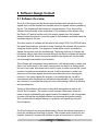
8. Software Design……………………………………………………………………51
8.1 Software Overview………………………………………………………..51
8.2 Emotiv Software…………………………………………………………..52
8.3 Custom PCB (Arduino) Software……………………………………….66
9 Design Summary of Software……………………………………………………..73
9.1 Emotiv Software…………………………………………………..73
9.2 Custom PCB (Arduino) Software……………………………….78
10. Design Summary of Hardware…………………………………………………..88
10.1 Design Summary of Hardware…………………………………………88
10.1.1 RC Car Hardware Design Overview………………………...88
10.1.2 RC Car Processor Overview…………………………………84
10.1.3 RC Car RF Interface Overview………………………………91
10.1.4 RC Car Structural Modification Overview…………………..94
10.1.4.1 Structural Modification Process…………………....94
11. Project Testing…………………………………………………………………….96
11.1 Headset Testing…………………………………………………………96
11.2 Software Testing………………………………………………………...99
11.3 Vehicle Testing…………………………………………………………108
11.3.1 Individual Component Testing……………………………...108
11.4 Arduino Testing………………………………………………………...109
12. Administration……………………………………………………………………118
12.1 Project Budget Estimate……………………………………………….118
12.2 Timeline/Milestones……………………………………………………119
12.2.1 September…………………………………………………….119
12.2.2 October………………………………………………………..119
12.2.3 November……………………………………………………..119
12.2.4 December……………………………………………………..119
12.3 Areas of Assigned Responsibility…………………………………….120
13. Summary and Conclusion…………………………………………………...…122
14. List of Figures…………………………………………………………………....124
15. List of Tables……………………………………………………………………..126
16. References……………………………………………………………………….127
17. Permission of Use……………………………………………………………….131
18. Appendices
iii
1: Executive summary
The idea of having the power to control physical objects with your mind has been
a fantasy of many people ever since first watching Star Wars. So for all of the
people who have ever wanted to use the force, this project is right up your alley.
The project that will be undertaken will be a small remote controlled car with an
onboard computer that will interpret EEG (electroencephalography) readings
from a headset worn by the user, and, depending on the type of brain activity
detected, either move the car forward, backward, left, or right. The reason for
incorporating EEG is to explore the emerging field of brain computer interface
(BCI). Until recently the field of BCI has been primarily focused on that of
neuroprosthetics applications that aim at restoring function to damaged parts of
the body, but now, commercially available headsets make it possible for the field
to broaden its view. Theses commercially available headsets are intended for
use with videogames and integrating with the user’s ordinary computer allowing
for endless possibilities.
The main objective of the project is to design a functioning car that will respond
to a user’s brain activity and respond accordingly. Being used will be an Emotiv
EPOC EEG headset to gather the necessary brain readings to drive the car. To
run our custom architecture we will be using the Intel DH61AG mini-ITX
motherboard with in Intel core i3 processor to communicate with a custom
Arduino PCB that will translate a string sent out by a translation program on the
mainboard and convert it into an 8 bit format that is able to be read by the custom
PCB on the car. The car itself will house another custom PCB that will have a
serial to parallel converter to drive the motor. The car also will have limiters on its
actions, such as a speed limiter, so it does not wildly speed off when a signal is
received and steering limiters, which decrease the turning angle to just 45
degrees so the user is able to control the car more fluidly and accurately.
This paper describes how each of the components listed above were researched
and how they were implemented, including a budget and a timeline for finishing
the EPOC-alypse mind controlled car for the final senior design presentation. In
order to make the car respond as accurately as possible training on the Emotiv
headset is essential. The ability to focus your mind and activate certain areas of
the brain on command is the key to making this entire project work.
No experts or guidance from anyone who has used the headset before or who
has in depth knowledge on the brain were referred to during the course of this
project. This resulted in a well refined knowledge of how specific areas of the
brain worked and what the thoughts that controlled the car actually meant.
1
There are also requirements from the hardware and software interfaces that will
be dealt with, these are listed in the body of this paper. All these requirements
led us to our budget, which since our group is unsponsored, was initially a fairly
small number due to the financial situation of team members. This, however,
changed dramatically due to the hardware that was required to run all of our
systems properly. This is outlined more in the budget section of the paper.
2: Introduction
2.1: Motivation
Brain computer interface seems to be narrowly focused on the medical
applications, but a much broader applicability of BCI exists than just medical
uses. This project aims to expand into the realm of alternative uses for BCI by
applying it to everyday activities. As more is understood about the brain and how
it works, the more its power will want to be harnessed. Manipulating physical
objects just by thinking is the ultimate goal for this area of interface. As a group of
electrical and computer engineers the prospect of this is too enticing to pass up,
therefore a mind controlled car was the perfect choice. The ability to apply this
project to people who no longer and move their arms and legs was also a driving
factor, just by simply replacing the remote for the car with the joystick for a
wheelchair someone who is confined to a bed or otherwise immobile can become
mobile.
2.2: Project Objective/Goals
The objective of this project, on paper, is quite simple: to build a remote
controlled car that is controlled by your mind by using the Emotiv EPOC EEG
headset. We came up with this project due to a unanimous interest by all
members in the group.
Our goal is to control the car using thoughts via Emotiv EPOC.
Control the car using a mini ITX board
Get the commands from Emotiv EPOC and process them.
Design an architecture to connect both the ITX and Emotiv, and that is
extendable to incorporate multiple devices.
2
Establish adequate connections and fine tune the signals for smooth
controlling of the car.
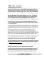
The initial purpose of this project is to practically solve a way to manipulate
physical objects with your mind. The main goal will be to navigate the car using
the headset through a simple obstacle course. This course will consist of left and
right turns on a circular track.
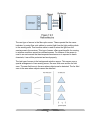
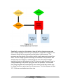
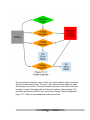
User
with
Headset
•Preforms
desired
thought
•Signal
transmitted
ITX
Mother
Board
•Signal
received
•Signal
interpreted
RC Car
•Remote
activated
•Car moves
in desired
direction
Figure 2.1 Basic flow diagram of how the EPOC-alypse car will work.
There are also many personal goals associated with this project as well. Many of
which included getting hands on experience with the various topics and
technologies, which would like to be pursued further in future careers. The more
experience that is gained while working with a brain computer interface such as
Emotiv’s, the more we can explore the emerging technologies that incorporate
the human brain.
3
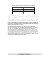
2.3: Specifications
Below is a brief list of specifications that are a necessity for the project. These
guidelines are the main aspects of the design that will have to be obtained for the
project to work. Everything else can be changed.
Headset proficiency
Control four different actions
Mastery of isolating thoughts
2.4 GHz processor
1 GB RAM
50 MB disk space
USB 2.0 port
Range of 40ft
Full range of motion
Motherboard
Car
(Table 2.1) Specifications table
2.4: Previous Works
Using the power of the human mind to control everyday objects had always been
a fantasy for people. The possible applications and benefits of reading and
interpreting brain-waves are endless. Examples of possible uses include medical
devices for doctors and patients, new ways to control devices without a remote
control, etc. Recently, however, several projects have arisen that have started to
make this fictional desire into a reality. Projects such as the BrainDriver, the
SWARM Extreme, RC Mind Control, and Brain-Controlled NXT Robot are
beginning to use brain-waves as a means of allowing a user to control devices
and applications. These projects are very similar to this project because they
incorporate the use of an EEG headset and use data from it to control a device
with brain waves or facial expressions.
4
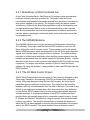
2.4.1: BrainDriver: A Mind Controlled Car
At the Freie Universitat Berlin, Raul Rojas an AI professor have demonstrated
how brain interface can drive an actual car. The project uses the Emotiv
neuroheadset that feeds the commands received from the driver to the drive-bywire system installed on the vehicle. The thoughts control the engine, breaks,
and steering. While nifty the BrainDriver application is still a demonstration and
not road worth because there is a two to three second delay in the response
time. But the researchers say that future applications could be an autonomous
cab ride, where a passenger could decide which route to take when more than
one possibility exist.
2.4.2 The SWARM Extreme
The SWARM Extreme was a project carried out at Northeastern University in
2011 (Bothra). This project used the Emotiv EPOC headset to control an AR
Drone without the use of a remote control. The processor used for this project
was an ARM9 processor which was embedded in the AR Drone and interpreted
signals sent from the laptop running the Emotiv software. The software design
consisted of a client/server architecture that used the signals received from the
headset and processed them into usable signals for the drone (Bothra). A buffer
was used in the client in order to prevent over-whelming the Drone with too many
commands. The project used a library written in Python to hack the Emotiv
software. By using this software, it was possible to attain raw EEG data from the
EPOC headset.
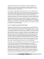
2.4.3: The RC Mind Control Project
The RC Mind Control project was carried out in The Center for Research in Arts,
Technology, Education, and Learning (CRATEL) at Wichita State University.
Initially, this group attempted using the NeuroSky headset, but found that its
capabilities were not sufficient for this project. They found that the NeuroSky
headset could only read brainwaves from one side of the brain. This made it very
difficult to get usable and accurate data. After discovering this, they decided to
use the Emotiv EPOC headset due to its more mature development and more
accurate readings. A very important feature of the EPOC headset was that it
provided them with enough data points to incorporate research done by Jonath
R. Wolpaw and Dennis J. Mcfarland by using an equation that was determined
by these two authors. The equation allowed them to calculate the direction in
which the RC car was supposed to move by using the amplitudes of the signals
sent by the EPOC headset. This group decided to use an Arduino board to
5
communicate with the remote control of the car. Instead of connecting the
Arduino to the circuit on the car, they decided to connect the Arduino to the
actual remote control. The Arduino then sent processed signals to the remote
control which were then sent to the car.
The operation of this prototype required the user's level on concentration to be
above a level of 0.599. The level of concentration as well as the position of the
user's head were determined using the various suites included in the Emotiv SDK
as well as the built-in accelerometers. Once the level of concentration was
interpreted to be above .599, the Arduino processed the received signal and sent
the proper signal to the remote control. The direction in which the car moved was
determined by the position of the user's head. For example, to move the car
forward, the user had to tilt his head up. After a signal was received, the software
waited for the next signal from the headset to reach the Arduino board. When the
user wished to stop the car, he simply relaxed his level of concentration and tilted
his head back to a centered position.
2.4.4: The Brain-Controlled NXT Robot
The Brain-Controlled NXT Robot was a project carried out by a PhD student at
Madeira Interactive Technologies Institute. Although this project does not control
a car, it is a similar project to ours because it uses the EPOC headset to control a
Lego Mindstorms NXT Robot. This project used an ARM7 microprocessor which
was embedded in the robot. This project consisted of two prototypes. One of the
prototypes used the NeuroSky headset and the other used the EPOC headset.
This was done in order to show the different features and functionalities of the
two distinct headsets. The NeuroSky headset used an algorithm provided by
Neurosky in order to get attention and meditation levels of the user. The patterns
that were found by the headset were then used to send commands to the robot.
The Emotiv EPOC headset, on the other hand, used facial expressions as well
as frustration, excitement and other emotions in order to produce data.
The software used on the ARM processor included a Java Virtual Machine called
LeJOS. This was used as the OS for the project because it provided the
"extensibility and adaptability of JAVA" (NXT ROBOT). This was important for
this project because Java was the programming language used in this project
with the use of Eclipse as the IDE. In order to connect the computer and the
robot, a Bluetooth connection was used along with the pccomm and bluecove
libraries found in the LeJOS API. This project used a very similar technique as
the RC Mind Control project because they used a threshold value to determine
when the signal sent by the headset was strong enough to be considered
6
intentional. In order to determine the threshold value, readings were taken for
concentration levels while calm, normal and concentrated. These values were
used to determine a level that would certainly determine when the user was
concentrated. This experiment was conducted with five different users, thus
making the results more general for all users. When the concentration level
dropped below the threshold, the robot was instructed to stop moving. In order to
monitor the attention levels of the user, the NeuroSky headset used the Mindset
development tools along with a software program called LiveGraph, which plotted
the concentration levels of the user with real-time data.
After researching many projects, these three examples were most relevant to the
project that this group will be designing. Different headsets were analyzed as well
as different devices such as cars, drones, boats, etc. This was very useful for this
project because it helped minimize time wasted on ideas and procedures that
would not have worked. By looking at the implementations of other projects,
ideas were found that will allow this project to be more successful.
7
3: Project Definition and Scope
3.1 Definition and Scope
The EPOC-alypse controlled Car is a project that will combine the efforts of both
computer software and hardware components. Both areas of study will work
together in this project in order to control a remote control car by reading and
interpreting EEG waves from the human mind as well as facial expressions. The
final functionality of this project will be to be able to run the developed software
and control the car without having to use any remote controls or having any other
human interaction with the car. The scope of the project will be a final product
that can function as stated above and that can be finished within one semester of
research and one semester of work.
3.2 Span
The span of this project will consist of many fields of study including device
communication, signal processing, hardware manipulation and many others.
Device communication will be used in order to send the signals from one
component to another. Without this knowledge, it will be impossible to
accomplish the main task of the project. Signal processing will be used in the
software aspect of the project. The signals received from the headset will be
processed and categorized as being either cognitive or effective. Once this
classification is done, the signals will be further processed into useful signals for
the car to use. Hardware manipulation will be a very important aspect of this
project. The car that we use in this project will have a custom PCB attached to it
which will contain many sensors and components that will specifically used for
the intentions of receiving signals from the motherboard and transmitting the
correct voltages to the correct wires on the car. This PCB will control the motors
as well as the servo motors and the piezoelectric ultrasonic proximity sensor on
the car. There will also be a custom PCB connected to the motherboard that will
be used in the signal processing aspect of the project. This PCB will be made to
mimic an Arduino board and will convert strings into 8-bit streams of data that will
then be used by the car to determine which command it should execute.
8
3.3 Assumptions
As with any project, there will be some assumptions made while making this
project. First of all, it will be assumed that the environment in which the system is
used will not cause any significant interference with the signals being sent by the
headset. The signals being sent to the motherboard will need to be considered
valid and if any signals are corrupted or lost, there is the possibility that the car
will behave unpredictably. Also, it will be assumed that the user will have a
complete mastery of the headset prior to using the project. Although it would be
beneficial to assure that anyone can use the project, unfortunately the Emotiv
EPOC headset requires much training before the signals sent by the user can be
considered reliable. This is, of course, something that we cannot change and
therefore we will be assuming that the user wearing the headset will be one of
the group members which will have gone through all the necessary training in
order to use the headset effectively.
3.4 Requirements
There will be a couple of specific requirements that will need to be fulfilled by the
end of the project. The most basic requirement will be a functional car that will be
able to respond to the signals sent by the EPOC headset. The other requirement
for the project will be that it will be able to work as long as it is kept in range. The
receiver on the car and the transmitter on the motherboard will have a maximum
range that will ensure reliable signal transmission. The car will need to be able to
function as long as it remains within this range, meaning that there will not be any
bugs or unhandled exceptions in the software. There are no requirements for
how fast the car will travel. This will be determined through testing.
3.5 Measuring Success
The overall success of this project will be measured by how accurate the car's
actions are compared to the signals sent by the user. This will mean that both
correct actions and response times will be taken into account. In order to achieve
these results, it will be important to have hardware components that will meet all
the requirements necessary to run the Emotiv software as well as transmit all the
signals from the headset to the motherboard and from the motherboard to the
car. It will also be important to develop software that will be able to interpret and
process signals efficiently enough to produce real-time execution
9
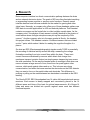
4. Research
Brain-computer interface is a direct communication pathway between the brain
and an external electronic device. The goals of BCI are often directed at assisting
or augmenting human cognitive or sensory motor functions. Recently neural
interface devices have become available on the market for gaming and other
virtual uses. Neurosky, a company who offers one of these headsets gathers raw
EEG data to use with applications on iOS and Android platforms. Their headset
contains one sensor on the frontal lobe to collect multiple mental states. As the
company puts it “the physics of brain waves is virtually identical to the physics of
sound waves where a single microphone can pick up the complexity of the
concert.” Another company who is in the same market is Emotiv, the headset
this project utilizes. This headset contains 14 different sensors that are divided
up into 7 pairs, which makes it better for reading the cognitive thoughts of a
person.
So what are EEG (Electroencephalography) signals exactly? EEG is essentially
the recording of electrical activity across the scalp, measuring the voltage
fluctuations resulting from ionic current flows within the brain. These ionic
current flows are maintained by neurons which obtain their charge from
membrane transport proteins that act as simple pumps transporting ions across
the cells membrane. So the way the headset picks up readings is that when one
neuron releases a large amount of ions, these ions can push against other
neurons, which push against others and so on. This is known as volume
communication, and when that wave reaches the electrodes on the EEG detector
they can exert a force on the metal inside each electrode. This difference in
pushing or pulling on the metal between two electrodes is recorded as the EEG
reading.
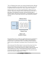
The Emotiv EPOC EEG Neuroheadset has 14 saline felt based electrode sensor
receivers. Each sensor is ideally mapped and conveniently placed in the 14
different areas and lobes of the brain for optimal measurements. All of these 14
lobes and areas are divided into specific regional areas each has different
functional aspects.
10
The FRONTAL LOBE : Planning, Language, Expression and Speech
contains the Motor cortex area involved in movements (movement,
conscious thought , and controls voluntary movement of body parts ),
PARIETAL LOBE: Touch, Taste contains the Somatosensory cortex
areas ( receives and processes sensory signals from the body) ,
OCCIPITAL LOBE visual area (contains the visual cortex ) receives and
processes signals from the retinas of the eyes,
TEMPORAL LOBE :Language Reception.
Figure 4.1 Lobe locations on the brain.
The 14 channels AF3, F7, F3, FC5, T7, P7, O1, O2, P8, T8, FC6, F4, F8, AF4
shows real time brain wave activity divided into common brain wave frequencies
Alpha, Beta, Theta and Delta. The sense 14 locations are given in the Hardware
overview of the Headset section which has a diagram of each of the sensors to
11
be used and how they are each mapped to specific areas for different types of
readings in the brain based on activity.
4.1 Brain Waves
These waves that are produced from the volume communication between
neurons can be classified into; Delta, Theta, Alpha, Beta, and Gamma waves.
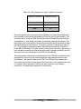
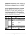
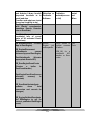
There are also Mu waves but for or project these are irrelevant. The table below
describes the frequency of each wave and what state of mind each occurs at.
Wave Type
Delta
Location
Frontal cortex
Theta
Locations not
related to task
being preformed
Posterior regions,
either side of the
brain
Either sides of the
brain but mostly in
frontal region
Somatosensory
cortex
Alpha
Beta
Gamma
Frequency (Hz)
0 - 4 (high
amplitude)
4-8
States of Mind
Asleep
8 – 13
Relaxed, eyes are
closed
13 – 30
Alert, working,
anxious, busy
30 – 100
Cross modal
sensory
processing (i.e.
combining sight
and smell)
Drowsiness,
Idling, Arousal
(Table 4.1) Brain wave types and characteristics.
The project utilizes mostly Beta and Theta waves, thought delta waves seemed
to present themselves more in the evening when the mind starts to start its night
cycle.
While the type of brain waves that are exhibited are useful for initial training to try
and obtain the proper mind set it is not what is being quantified for the EEG
readings to control the car. This comes from the locations of the sensor pairs
oriented around the skull. These areas are referred to as Brodmann areas.
12
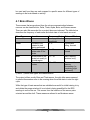
4.2 Brodmann Areas
A Brodmann area is a region of the cerebral cortex defined based on its
cytoarchitectonics, or structure and organization of cells. Many of these areas
have been defined solely on neuronal organization and have since been
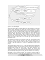
correlated closely to a wide range of cortical functions. Below in figure 4.1is a
rough diagram of where each area is located in the brain.
Figure 4.2 Brodmann areas.
German anatomist Korbinian Brodmann published his maps of cortical areas in
humans, monkeys, and other species in 1909, but a more detailed map was
published by Constantin von Economo and Georg N. Koskinas in 1925.
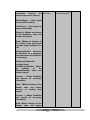
The Emotive headset is located over 7 of the most prominent of these Brodmann
areas, the Dorsolateral prefrontal cortex, frontal eye fields, anterior prefrontal
cortex, primary gustatory cortex, middle temporal gyrus, primary motor cortex,
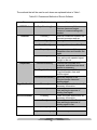
and the somatosensory association cortex. These areas are displayed in table
4.2 in relation to their location in the brain, and in table 6.2 referencing which
sensors are over which area.
13
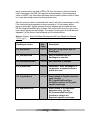
Area Name
Dorsolateral prefrontal cortex
Frontal eye fields
Anterior prefrontal cortex
Primary gustatory cortex
Middle temporal gyrus
Primary motor cortex
Somatosensory association cortex
Brodmann Area Number
9
8
10
43 (not show on diagram)
21
4
7
Table 4.2 Brodmann areas and locations
4.2.1 The Dorsolateral Prefrontal Cortex
Also known as DL-PFC is part of the “primate” part of the brain and actually
consists of Brodmann areas 9-12, 45, 46, and 47. It acts as the highest cortical
area responsible for organization, motor planning, and regulation. “It is
responsible for integration of sensory and mnemonic information and the
regulation of intellectual function and action.” It is involved in all complex mental
activity but requires the additional cortical circuits that are connected to other
regions.
.
4.2.2 Frontal Eye Fields
This area is located in the prefrontal cortex which is ultimately connected to the
frontal cortex of the primate brain close to the skull. Also referred to as FEF the
frontal eye fields control eye movements and visual attention. The area is
activated during the initiation of eye movements such a blinking, rapid eye
movements, and twitches. There is also evidence to suggest that the FEF plays a
role in a purely sensory processing way as well. But together with the
supplementary eye fields, the intraparietal sulcus, and the superior colliculus, the
FEF controls all eye related movement.
14
4.2.3 Anterior Prefrontal Cortex
The anterior prefrontal cortex which is part of Brodmann area 10 which also
includes the rostral and frontopolar prefrontal cortex, is the largest
cytoarchitectonic area in the brain and not much is understood about this region.
Best guess is that this area is involved in strategic processes in memory retrieval
and executive function. It is proposed that ‘cognitive branching’ occurs here
which enables a previously running task to be maintained in a pending state
while the task at hand is comleted.
4.2.4 Primary Gustatory Gyrus
One of the least understood areas of the brain. No official information could be
found.
4.2.5 Middle Temporal Gyrus
Located on the temporal lobe, the middle temporal gyrus’ exact function is
unknown but has been connected with processes ranging from contemplating
distance, recognition of known faces, and accessing word meaning while
reading. It should be noted that this area is for reference while using the Emotive
headset.
4.2.6 Primary Motor Cortex
The primary motor cortex work in unison with the premotor cortex, the
supplementary motor area, and posterior parietal cortex to send synapses down
the spinal column. It contains large neurons called Betz cells, which send long
axons sown the spinal cord. The PMC contains a rough map of the body with
different parts of the body controlled by partially overlapping regions of the cortex
arranged from toe to mouth.
4.2.7 Somatosensory Association Cortex
Also known as SAC, the somatosensory association cortex has been linked to
involvement with speech language and also movement. It has been seen that a
reduction in SAC activity is a response to speaking, so the area appears to be
activated by simple rather than complex sensory stimuli.
15
4.3 Reasons for Specific Testing Reactions
4.3.1 Temperature Change
During headset testing method tried to induce difference brain activity was
drastically changing the temperature of an extremity. This was thought to
produce a different pattern to help control a second action for the 3D cube in the
Cognitiv suite in the Emotiv software, which is explained more in section 6 and
11. The guess was that by altering the temperature of a specific body part, a
change in brain activity would present itself but to the tester’s surprise, it did not.
Temperature responses in the brain are in the preoptic are of the hypothalamus
which is in the midbrain tegmentum (split). It has been seen that “a mechanism is
initiated to deliver more blood to this region to compensate for the temperature
induced drainage of blood out of the brain. A compensatory reaction is generally
observed in mammalian brains to supply oxygenated blood to accommodate
increased oxygen consumption by cells.” (Ogawa et al. 1992)
The problem with this was that the hypothalamus is too far inside the brain to
register its activity on Emotivs, sub-medical grade equipment. Therefore no
stable or strong response was seen.
4.3.2 Music
Another method tested for trying to induce a different kind of response in the
brain was having the user listen to different kinds of music. First off it has been
that people like listening to music for the same reason they like eating or having
sex. All 3 of those activities release the chemical called dopamine. Had this been
researched before testing it could have been deduced just from that statement
that music was not a wise choice for stimuli because it has been seen that brain
patterns of a person eating or having sex are, while elevated, quite erratic in
nature.
Researchers at McGill University in Montreal conducted a study with eight people
who consistently felt chills from particular moments in some of their favorite
music. PET (positron emission tomography) showed that the participant’s brains
pumped out a profuse amount of dopamine while listening to favorite pieces of
music as opposed to just a slightly elevated amount when listening to other
music. “It was seen that dopamine surged in one part of the striatum during the
16
15 seconds leading up to a thrilling moment, and a different part when that
musical highlight finally arrived.”
This information backed up the tests conducted by our group when increased
brain activity for specific genres of music showed up compared to others. The
fact that this region of the brain is always elevated while listening to music was
promising but eventually led nowhere because of the extreme changes in the
elevated activity due to the uses specific taste in music.
4.3.3 Pain
The last testing method tried (for obvious reasons) was that of inflicting pain on
the user by the insertion of a thumb tack into a shoe and then having the tester
put on the shoe.
First off, nociception is what the sensation of pain is called, and while pain seems
to be related to the sense of touch, the two register on a completely different
neurological level. Once pain is detected its sent to the spinal cord and up to the
brain,( it is fascinating to note that the signal crosses over to the opposite side of
the spinal cord and then is sent to the brain, so a feeling of pain on the right side
of the body is a signal that climbs up the left side of the spinal cord) once in the
brain the sense of pain is registered by many areas but most predominantly the
somatosensory association cortex.
As stated above in the previous section, the somatosensory cortex is toward the
top of the brain and close to the skull which makes is easily detectable by the
Emotiv neuroheadset. Once this was seen in testing more was done to provoke a
more intense response. It was found that when pain that is induced by tissue
damage (i.e. cuts and bruises) the nociceptors become even more sensitive to
pain, a phenomenon known as hyperalgesia. When cells are damaged
histamine, serotonin, and prostaglandin are released into the area of the injury
making the neurons send the sensation to the brain quicker. Ultimately the
neurological response is the same, at least for minor injuries.
So because of the Emotiv Neuroheadsets position of sensors O1 and O2 right
over the somatosensory association cortex , described more in section 6, the
external stimuli was decided on being pain.
What was more fascinating that the very predominant display that pain had on an
EEG, was that the brain started to mimic the pain response on the EEG without
any pain being inflicted.
17
What could be gathered about this phenomenon was that, with the tester having
conscious knowledge of how the pain of the tack in the shoe feels, and physically
looking at the shoe with the tack in it, the brain knew it was supposed to be
registering pain to perform the action on the 3D cube in Emotivs Cognitiv suite.
But the tester felt no pain what so ever, the adaptive ability of a trained brain was
absolutely remarkable. Regrettably no published paper on this phenomenon
could be found.
INFLICTING PERSONAL INJURY WAS
ANY OF THE TESTS PREFORMED.
18
NOT DONE FOR CONDUCTING
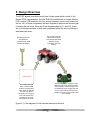
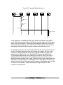
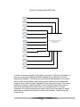
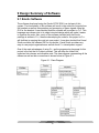
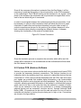
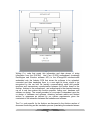
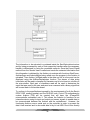
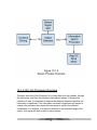
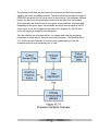
5. Design Overview
The EPOC-alypse controlled car will have 5 major parts which consist of; the
Emotiv EPOC neuroheadset, the Intel DH61AG motherboard, a custom Arduino
PCB, custom PCB located on the car, and an ultrasonic sensor array located on
the car. All 5 of these components will work together to achieve the ultimate goal
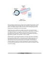
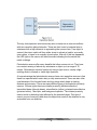
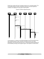
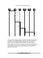
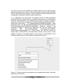
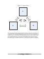
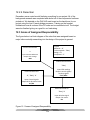
of making the car move. Show are 2 flow diagrams(figures 5.1 and 5.2); these
are a visual representation of that each component looks like and a summary of
what each part does.
Wireless signal sent
from DH61AG
motherboard by USB
wireless transmitter.
The car will house the
custom PCB under the
hood and the HC-SR04
ultrasonic sensor
mounted on the front
bumber.
Custom PCB
The HC-SR04 is the ultrasonic range
finder that will act as a buffer between
the car and any immobile object. The
HC-SR04 will act as a trigger that will
send a code of all 0's to the serial to
parallel converter to stop all motor and
servo function.
The custom PCB will
have a wireless USB
receiver incorporated to
collect the 8 bit data sent
from the main board.
Depending on the type of
8 bit code the serial to
parallel chip will send
commands to the motor.
(figure 5.1) Flow diagram of how onboard electronics will work
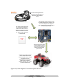
19
Emotiv Headset gathers EEG
information and transmits it via
Bluetooth to the DH61AG
board
The Bluetooth signal is receive via the
Emotiv Bluetooth dongle that plugs into
one of the USB ports. This signal is
then translated into a string and sent to
a custom arduino board.
The custom Arduino board will
be connected via USB to the
DH61AG and will receive the
strings and convert them into 8
bit format needed to move the
car. These are then sent back
to the DH61AG.
Custom
PCB
Once the 8 bit code is back
on the mainboard it is sent
to the car using a wireless
USB receiver/transmitter
pair to the car.
Onboard the car will be another
custom made PCB what will
house the USB receiver and the
processor for the car.
Depending on the 8 bit code
produced by the Arduino,
forward, backward, left, or right
movement should result.
(Figure 5.2) Flow diagram of how entire system will work.
20
6: Hardware Overview
6.1: Headset
The Emotiv EPOC headset is an affordable easy to use marketed EEG recording
device. Targeted at the emerging BCI video games market, Emotiv aims to
enhance the gaming experience. Emotiv’s design also has attracted the interest
of neuroscientists due to the setups low price, running inexpensive experiments
from one’s own computer.
The Emotiv headset is the key to the entire project, being what obtains and
transmits the neuro-signals. The headset comes with 14 independent sensors
that consist of felt pads with gold connections to increase the sensitivity of the
pickups. These felt sensors need to be moist at all time to conduct the potential
difference across the skull, this is done by using a saline solution.
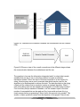
The placement of the headset on ones scalp is also an integral part to the
acquisition of signals. As the headset is carefully slipped on it is key that to place
the sensors with the black rubber insert on the bone just behind the ear lobe, as
shown below in figure X
(Figure 6.1) Shows the correct placement of the headset with respect to the
rubber reference sensor.
21
It should be noted that the two front sensors should be approximately at the
hairline or three fingers above the eyebrows. After the headset is in position
check to see that there is good contact by the reference nodes, this is essential
because a bad connection with these sensors will not produce any readings.
Once the headset is connected via the wireless USB receiver the headset setup
panel is displayed. The main function of this panel is to display the contact quality
feedback for the neuroheadset’s EEG sensors.
The EPOC headset has sixteen electrodes to measure the potential difference
across the skull. However there is no official reference for the user wearing the
headset so the electrodes are actually paired up, and the difference between a
pair is used as the measured signal. So when the user is training a certain action
to manipulate a 3D cube with the Cognitiv suite, it is comparing how the values of
a pair of electrodes change. Therefore whenever it sees a similar change, the
software recognizes that you are trying to perform a specific action on the cube.
(Figure 6.2) A screenshot of the headset setup panel showing all good
connections for all 14 sensors.
22
This image represents the sensor locations as seen when looking down from
above onto the user’s head. Each circle represents one sensor and its
approximate location when wearing the headset.
Number of channels
Channel names
14 (plus CMS/DRL references
AF3, AF4, F3, F4, F7, F8, FC5, FC6,
P3 (CMS), P4 (DRL), P7, P8, T7, T8,
O1, O2
Sequential sampling, Single ADC
128 Hz (2048 Hz internal)
16 bits
0.2 – 45 Hz, digital notch filters at 50
Hz and 60Hz
256 mVpp
AC coupled
Proprietary wireless, 2.4 GHz band
Li-poly
12 hours
Contact quality using patented
system
Sampling method
Sampling rate
Resolution
Bandwidth
Dynamic range
Coupling mode
Connectivity
Battery type
Battery life
Impedance measurement
(Table 6.1) Emotiv neuroheadset specs.
Source: Emotiv. Emotiv Software Development Kit User Manual for Release
1.0.0.5.
23
6.1.1 The Three EMOTIV Acquisition Suites
There are three Emotive acquisition suites; the Expressiv suite, the Affectiv suite,
and the Cognitiv suite. Each of these uses a different kind of interpretation of the
sensor’s signals to display different kinds of reading.
6.1.1.1 The Expressiv Suite
(Figure 6.3) The EXPRESSIV suite control panel.
While in EXPRESSIV suite, the avatar on the left of the screen will actually mimic
the user’s facial expressions. While at the same time the graphs to the right of
the avatar will indicate which of a various amounts of facial expressions are
being registered. These graphs show short history of the detections listed, and
can be interpreted as follows:
24
Blink: low level indicates a non-blink state, while a high level indicates a
blink.
Right Wink / Left Wink: these two detections share a common graph line.
A center level indicates no wink, low level indicates a left wink and high
level indicates a right wink.
Look Right / Left: these two detections share a common graph line and a
single sensitivity slider control. A center level indicates eyes looking
straight ahead, while a low level indicates eyes looking left, and a high
level indicates eyes looking right.
Raise Brow: low level indicates no expression has been detected, high
level indicates a maximum level of expression detected. The graph level
will increase or decrease depending on the level of expression detected.
Furrow Brow: low level indicates no expression has been detected, high
level indicates a maximum level of expression detected. The graph level
will increase or decrease depending on the level of expression detected.
Smile: low level indicates no expression has been detected, high level
indicates a maximum level of expression detected. The graph level will
increase or decrease depending on the level of expression detected.
Clench: low level indicates no expression has been detected, high level
indicates a maximum level of expression detected. The graph level will
increase or decrease depending on the level of expression detected.
Right Smirk / Left Smirk: these two detections share a common graph
line. A center level indicates no smirk, low level indicates a left smirk and
high level indicates a right smirk.
Laugh: low level indicates no expression has been detected, high level
indicates a maximum level of expression detected. The graph level will
increase or decrease depending on the level of expression detected.
25
This control panel also includes sensitivity adjustments by moving the sliders on
the right for each of the corresponding graphs.
EXPRESSIV supports 2 types of signatures that are used to classify input from
the headset as indicating a particular facial expression, a preprogrammed
universal signature or a trained signature. The foremost being what the average
readings for blink, wink, etc. would be and the latter being the use performs an
action, such as blink, and the program remembers it for future use.
6.1.1.2 The Cognitiv Suite
This suite detects and evaluates a user’s real time brainwave activity to discern
the user’s conscious intent to perform distinct physical actions on a real or virtual
object. The detection so designed to work with up to 13 different actions including
directional movements and rotational movements and an extra action that exists
only in the users imagination which is to make something disappear.
The suite allows the user to choose up to four actions that can be recognized at
any given time. The detection reports a single action or neutral, which would be
no activity at a time, along with an action power which represents the detections
certainty that the user has entered the cognitive state associated with that action.
The tricky part being that increasing the number of concurrent actions increases
the difficulty in maintaining conscious control over the Cognitiv detection results.
This is where training would come into play. New users gain control over a single
action quite quickly but learning to control multiple actions requires practice and
adding more actions quickly increases the difficulty,
The Cognitiv suite control panel uses a virtual #D cube to display an animated
representation of the detection output. This cube is used to assist the user in
visualizing the intended action during the training process. In order to enable the
detection, each chosen action, plus the neutral action, must be trained. The suite
enables the EmoEngine to analyze the uses brainwaves and develop a
personalized signature which corresponds to each particular action as well as the
background state of neutral. As the engine refines the signatures for each of the
actions, detections become more precise and easier to perform.
26
(Figure 6.4) the Cognitiv control panel with interactive 3D cube to simulate the
action that the user is intending to accomplish.
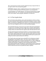
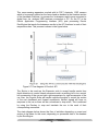
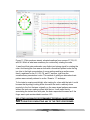
6.1.1.3 The Test Bench
The Test Bench software is a real time EEG reading that displays the output of
all 16 sensors. It can be noted early on that facial expressions such as blinking,
smiling, and teeth clenching, are all very discernible due to the fact that the brain
activity that is signaling these actions is very close to the top of the skull.
It is from the test bench that it can be seen where the increase in brain activity is
coming from for training the Cognitive actions for the car. By being able to see
the level of activity in a specific area of the brain, it is much easier to isolate ones
thoughts and learn to activate the region on demand.
The figures below illustrate a few of the most noticeable readings from a few
facial expressions. Though the sensitivity of the headset limits the detection of
thoughts that can affect the Cognitive suite in manipulating the 3D cube.
27
(Figure 6.5) This is the EEG reading from clenched teeth. The active areas are
areas that are toward the front of the head. The short spike is from a short clench
and the longer one is from prolonged clenching.
28
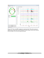
(Figure 6.6) Here, blinking is shown. The spikes in the black circle reflect a
normal blink while the spikes in the red circle reflect a much harder and intense
blink.
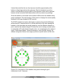
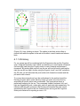
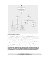
6.1.1.4 Emokey
For our project we will be combining both the Expressiv suite and the Cognitive
suite. Using the Expressiv suite’s facial cue detection to control lateral movement
(left and right) and using the Cognitiv suite to control forward and backward
movement. By winking with ones left eye the car will turn left and by winking the
right the car will turn right. And by using the Cognitiv “push” and “pull” actions for
the 3D cube, we will associate the push action with forward movement and the
pull action with reverse.
To convey these instructions from the motherboard to the arduino board the
Emokey program will be used. Emokey maps out routes for instructions by
associating a specific action with a command. The figure below shows a
preliminary mapping for the car. The commands forward, backward, left, and
right are triggered by push, rotate right, wink left, and wink right respectively. For
instance with the push command, the Emokey will translate the push events
generated by the Cognitiv suite into forward motion as long as the Cognitive
suites push detection is reporting a score > 0.2
29
(Figure 6.7) Emokey mapping for controlling the car.
.
30
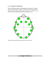
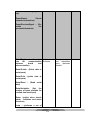
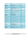
6.1.2 Headset Configuration
There are 16 different sensors on the headset that correspond to 7 different
areas of the brain as shown in figure 6.8. These sensors are arranged into 7
pairs; AF3 and AF4, F3 and F4, F7 and F8, FC5 and FC6, T7 and T8, P7 and
P8, O1 and O2, and DRL and CMS which are reference nodes.
(Figure 6.8) Sensor layout as viewed from the top of the skull.
31
Sensor
Sensor
Region of Brain
Number
Name
Sensor is Located Over
1
AF3
Dorsolateral prefrontal cortex
2
F3
Frontal eye fields
3
AF4
Dorsolateral prefrontal cortex
4
F4
Frontal eye fields
5
F8
Anterior prefrontal cortex
6
FC6
Dorsolateral prefrontal cortex
7
T8
Primary gustatory cortex
8
DRL (reference)
Middle temporal gyrus
9
P8
Primary motor cortex
10
O2
Somatosensory association cortex
11
O1
Somatosensory association cortex
12
P7
Primary motor cortex
13
CMS (reference)
Middle temporal gyrus
14
T7
Primary gustatory cortex
15
F7
Anterior prefrontal cortex
16
FC5
Dorsolateral prefrontal cortex
(Table 6.2) Sensor names and relative locations.
6.1.3 Headset Transmission
The headset actually transmits over Bluetooth and Bluetooth dongle, the Emokit
gets a connection to the Bluetooth device using a standard HID interface. Once
the connection is made it gets 32 byte reports from the device that are encrypted
to the Emokey language, these are then decrypted by using AES. The Emokit
then parses out the gyroscope data and the actual sensor data and sends it to a
queue that can be read in whichever manner is desired.
(Figure 6.9) Emotiv USB Bluetooth
receiver.
32
6.2: The car
The vehicle that will be used will preferably be small in size but it can range in
size from 6” in height to 12” in height. Although a smaller vehicle is preferred, it
cannot be too small as it will need to house multiple pieces of hardware on it in
order for it to function as intended. The vehicle will need to house:
one proximity sensor
a DC drive motor
a DC servo motor
several batteries
many small DC voltage regulators ranging between 5 and 10 volts
serial to parallel converter
receiver between the motherboard and the vehicle
A small Remote control vehicle will be used as a base that includes some of
these components but there will be a printed circuit board that will be created to
hold the rest of the parts needed for this project.
The proximity sensor will be placed on the front of the vehicle using a small
bracket or clip. The sensor will be used to ensure that no damage will be done to
the vehicle due to hitting or bumping into other objects. The sensor should be
small enough to be housed on the vehicle without interfering with other
components and without being interfered with itself. It will preferably be a
capacitive sensor that will be able to detect metallic and non-metallic objects
such as liquids, plastics, or woods from a distance of 35 cm to 1 m. Otherwise it
will be an inductive sensor that can only detect metallic objects from the same
distances.
A lightweight DC drive motor with an operating voltage of 6 volts will be used to
move the vehicle, the motor has a two wire connection where all the power for
the motor used in the vehicle is delivered between the two wires from the
battery. For the purposes of this project, the DC motor should have a maximum
spin of at least a few thousand RPM’s. The driving force of the vehicle will be a
variable DC voltage that is small and light enough to fit on the back of the vehicle
and does not interfere with the performance. The variable DC voltage will
preferably be in the range of 0-9 volts which should be strong enough to move
the vehicle at an acceptable speed.
33
The DC servo motor is the assembly of a normal DC motor, a gear reduction unit,
a position-sensing device, and a control circuit. The servo motor receives a
control signal that represents a desired position of the servo shaft, in turn power
is applied to the DC motor in the servo motor and it rotates within 200 degrees
back and forth until the shaft is in that position. The servo motor has a three wire
connection respectively, the power, ground, and control wires. The power wire
must have a 5 volt high current power source constantly applied to it for it to
function properly.
The two batteries that will be used to power the vehicle will be at least 12 volts
each in order to properly power the DC motor and the motherboard. In addition to
these requirements, the batteries will need to be at least 1000mA/H in order to
give an adequate amount of time to test the vehicles operation.
Voltage regulators will be used in order to properly power the serial to parallel
converter, the DC drive motor, and the DC servo motors. This will be done by
maintaining a constant voltage level so as to avoid any damage to the processor
in any way. One of the voltage regulators will control the DC servo motor to
change in the range of 0 to 5 volts to determine the extent of which the vehicle
will turn. The other voltage regulators will control the DC drive motor and the
serial to parallel converter.
There will need to be a system designed to control both the DC drive motor and
the DC servo motor. The most simple way to adequately control each of the
motors is to use an eight bit serial to parallel converter. This converter will be
needed to control the circuit for the DC drive motor.
The chosen motherboard will need to have a processor with an operating
frequency of at least 2.4GHz and 1Gb of random access memory, (RAM) and
also have at least two USB ports so that the transceiver can be inserted as well
as a mouse so that the programming can be done. The motherboard will be used
to connect the USB transceiver and run the EMOTIV software as well as the
wireless transmitter used to connect to the printed circuit board on the vehicle.
The USB transceiver will receive the information from the headset which in turn
will be sent to the written program and used to control specific actions on the
vehicle. For instance, when a certain brain wave or facial movement is
recognized, that in turn will be linked to an action to move the vehicle in the
forward, backward, left, or right directions. This will in turn be sent via the
wireless transmitter to the vehicle to be used to control the various actions. The
34
transmitter operates at a frequency that is free to use, 2.4 GHz, as to not violate
any laws instituted by the FCC.
6.3 The Motherboard
In order to run the Emotiv SDK as well as the developed software for this project,
a motherboard or mainboard will be used which will be wirelessly connected to
the headset as well as the car. While searching for a correct board, there were
many specifications that needed to be considered. The Emotiv software has a
few minimum requirements that we had to fulfill with our motherboard and
processor. First of all, the processor needed to have a clock rate of at least 2.4
GHz. This meant that we had to look for more modern processors that had higher
clock rates and more processing power. We also needed to find one that had at
least 1 GB of ram and 50 MB of disk space. This was much easier to find, due to
the large availability of memory with modern technology. These specifications, as
well as price, were the most prominent requirements we needed to find in our
motherboard.
After finding many suitable boards for our project, we decided to use the Intel
DH61AG Core i3/i5/i7 Desktop Thin Mini-ITX Motherboard. This motherboard
has many of the specifications we need for our project as well as a few others
that will make the project easier to implement. Some of the more important
specifications for this board were:
-
2.5 GHz processor clock speed
2 GB Memory
Expansion slots for PCI Express
10 USB ports
1 HDMI port
These features of the motherboard will make it easier to not only run the Emotiv
SDK and the developed C++ software, but the HDMI port will also allow us to
connect it to a monitor and view the Emotiv GUI while running the Emotiv
software. One problem we did find with the motherboard was that it did not
include a significant amount of disk space, which meant we needed to find an
external source of space. In order to make up for this, we found the Emphase
Industrial - S1 SATA Flash Module 2 GB. We decided on this module because
the motherboard we are using has SATA connections which can be used for
storage. This flash module has enough memory to be able to handle the Emotiv
SDK as well as the developed software we are writing for the project.
35
7: Hardware Design
7.1: Headset Hardware Design Overview
The hardware for the project will consist of four components; the Emotiv
neuroheadset, the Intel DH61AG core i3 desktop thin mini-ITX motherboard, a
custom built Arduino PCB, and a remote controlled car.
7.1.1 Emotiv Neuroheadset
The Emotive neuroheadset, as described in the overview, is an array of 7 sensor
pairs, 14 sensors total arranged mostly towards the front of the skull. These
sensors measure the dissimilarity between a pair and this difference is recorded
as the signal. The signal is then transmitted via blue tooth to the receiver which is
plugged into the DH61AG motherboard.
7.1.2 DH61AG Motherboard
The DH61AG core i3 mini-ITX motherboard is a second generation Intel core
platform with integrated HD graphics, HDMI, and onboard DC power. It features
the 2-chip Huron River platform which is capable of supporting Intel’s Core
i3/i5/i7 (sandy bridge) processors. The exact processor that has been chosen is
the Intel core i3-2100T Sandy Bridge LGA1155 that runs are 2.5 GHz which is
perfect for that task at hand.
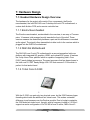
7.1.2.1 Intel Core i3-3220
With the i3-3220, one gets only two physical cores, but the 3220 features hyper
threading which adds an additional two virtual cores. This makes a sizeable
difference in performance over the Pentium models. Due to budget constraints,
the 3220 does lack turbo boost, thought, with its frequency limited to 2.5 GHz it
supports a cache configuration of 2x 256 KB of level 2 cache, 3MB of level 3.
36
7.2: Vehicle Hardware Design
7.2.1: Battery and Power
In order for the vehicle and all the components on it to be properly powered,
there were many things taken into consideration. One of which is what is the total
amount of voltage necessary for all the components being used on the vehicle to
function as required. After looking at the requirements for each of the
components being used, at least two 12 volt rechargeable battery packs will be
used. Rechargeable battery packs offer many benefits that regular non
rechargeable batteries do not offer. One of which being that they can often last
up to five times longer on each charge and are environmentally friendly.
There are many different types of batteries available that can be used for this
project. Many modern batteries use a variety of chemicals to power the reactions
that ultimately make the batteries work. There are Zinc Carbon, Alkaline, Lithium
Ion, Nickel Metal Hydride, and Nickel Cadmium, and Lead Acid. Zinc Carbon
batteries are very common in cheap AAA, AA, C, and D dry cell batteries.
Alkaline batteries are also very common in AA, C, and D dry cell batteries and
gets its name from the potassium hydroxide electrolyte. The lithium Ion
rechargeable battery is used in high performance devices such as cell phones
and digital cameras and Lead Acid rechargeable batteries is the last type and is
most commonly used in car batteries.
Focusing on the rechargeable batteries, the most commonly used is the Lithium
Ion battery. These are the most popularly used on the market for many reasons.
One of which being the fact that they hold their charge long term . It only loses
about 5 percent of its charge per month. Another benefit of this type of battery is
that it has no memory effect. In essence, this means that it is not necessary to
fully discharge the battery before recharging. Lithium Ion batteries can also be
used several hundreds of charging and discharging cycles without loss of use.
There are a few disadvantages to these types of batteries though. Once they are
fabricated, they only last between two to three years whether they have been in
use or not. They are also extremely heat sensitive. If they are in an environment
where there are high temperatures, the Lithium Ion battery packs will degrade
much faster.
37
Nickel Cadmium batteries were one of the first rechargeable batteries available
on the market. One of the greatest disadvantages to its use is the problem known
as the memory effect. In order for the battery to not lose its capacity, it needs to
be fully discharged every single time. This is when Nickel Metal Hydride batteries
came into favor. These batteries have a higher capacity in comparison and are
only minimally affected by the memory effect.
After much consideration, the two chosen 12 volt battery packs used will be
Nickel Metal Hydride (NiMH) with at least 1000mA/H to allow for adequate time
to test the vehicle and all components involved. Nickel Metal Hydride was chosen
because the batteries start out around 1.2 volts, but as it discharges it drops only
to about 1.1 volts before the battery is fully depleted. Even though the NiMH
battery starts at a lower voltage it provides a more usable voltage for a longer
duration of time. It also has a 30 to 40 percent higher capacity over a standard
Nickel Cadmium (NiCd) battery and are simple and easy to store and transport.
The current ratings of the batteries is very important as to have at least 30 to 40
minutes of drive time while powering both the serial to parallel converter as well
as all the vehicle components.
The dimensions of the batteries will most likely be .5” x 3.8” x 2.8” because it will
technically be four AA batteries connected together in each battery pack. The two
battery packs will be connected in series with the common node of the circuit
being that of where the positive of one battery meets the negative of another.
Many of the components in the vehicle will be run off of the positive terminal of
the batteries, so this in turn requires that the drive and servo motors will be run
off of the negative terminals. This will make it so that the other connected
components will still remain active when the battery that controls the vehicle has
been depleted.
It is also extremely necessary for there to be several voltage regulators in place
in order to control the various voltages that are needed to be supplied to each
circuit component. Voltage regulators are designed to regulate a constant voltage
level to all components involved. Since all of the components need between 5
and 12 volts to properly work, the LM7805 voltage regulator will be used. See
figure 7.2.
38
The LM7805 features a simple three terminal regulator with 5,12, and 15 volt
regulator options. It also includes internal thermal overload protection so as to
prevent damage to the component, due to overheating. With adequate heat
sinking the LM7805 can provide up to 1.5A of output current within the
temperature range of 0 to 125 degrees Celsius. Three separate voltage
regulators with different output supply voltages will be used to power all of the
subsystems needed to fully operate the project.
7.2.2: Sensors
In order to preserve the condition of the vehicle and to prevent any damage to it
due to foreign objects, one proximity sensor will be used on its front side. This
sensor will take information and relay it to the processor, where it can in turn
determine how to adjust its position accordingly. The proximity sensor will need
to be small in size and relatively inexpensive. There are many different types of
sensors, each with their own pros and cons. There are inductive, capacitive,
photoelectric, and ultrasonic sensors available.
Inductive proximity sensors are becoming more widely used in detection,
positioning, and counting of ferrous and nonferrous metal substances. They can
also detect metal through a layer of non metal material. The sensor itself is
comprised of an oscillator circuit, which is the actual sensing part, and an output
circuit with a switching device that is completely housed in a resin encapsulated
body.
39
The way that the inductive sensor actually works is when the inductance coil that
creates a magnetic field is disturbed, the circuit responds by closing the output
switch. The magnetic field is created on the front of the sensing face and is the
essential part in making the sensor work properly.
Capacitive proximity sensors are usually used as a last resort when all other
sensing techniques can not be used. They operate by responding to a change in
the “dielectric medium surrounding the active face and can thus be tuned to
sense almost any substance”. They can respond to all substances that have a
high dielectric constant, such as water, oil, fuel, or sugar.
Another benefit to using capacitive sensors is that they can sense a substance
through a layer of glass, plastic, or thin carton as well. These sensors are most
often used in level control of non conductive liquids, granular substances, or
sensing objects through a protective layer such as glass. A disadvantage of
using the capacitive sensors is the fact that deposits of excessive dust and dirt
on or around the sensing face can cause an erratic response and causes a need
of periodic cleaning.
40
The way that capacitive sensors actually work is based on an internal oscillator
with two capacitive plate electrodes. These are then tuned to respond when a
substance with a high dielectric is approaching the sensors face. If an object is
sensed, the output switch will then either close to activate a load for a normally
open option, or open for a normally closed option. After all of this has happened,
the LED light on the sensor will then illuminate indicating the the switch has
made a change.
Photoelectric sensors offer many benefits that other sensors do not. They have
non contact sensing of almost any substance or object up to a range of 10
meters. Photoelectric sensors function by using a light source, usually a light
emitting diode in infrared or visible light spectrum.
A huge advantage that photoelectric sensors have over capacitive sensors is that
these can operate better under dusty or dirty environments. These are also often
used because of the focused beam and long range which helps in sensing
distance and accuracy. There are many different types of photoelectric proximity
sensors. Of these types there are infrared proximity (diffused reflective),
transmitted beam (through beam), retroreflective (reflex), polarized retroreflective
(polarized reflex), fiber optic, and background rejection. The infrared proximity
sensor works by detecting light reflected by the intended target. This type of
sensor is most commonly used when the object that needs to be detected is only
accessible from one direction.
41
Another type of sensor is the transmitted beam photoelectric sensor. This uses
separate infrared transmitters and receivers so that when an object passes
through the infrared beam, it causes the receiver to output a signal. This signal
either closes a normally open switch, or opens a normally closed switch.
The next type of sensor is the retroreflective photoelectric sensor. These types of
sensors operate by sensing the light beam that is reflected back from a target
reflector. Just like the transmitted beam sensor, if an object interrupts the beam,
an electronic output is activated. Polarized retroreflective sensors work almost
the same as retroreflective sensors. The only difference being that it uses a
polarizing filter, designed so that shiny objects are easily detectible, in front of the
transmitter and receiver optics.
42
The next type of sensor is the fiber optic sensor. These operate like the name
indicates, by using fiber optic cables to conduct light from the light emitting diode
to the sensing area. Then another cable is used to return the light from the
sensing area to the receiver. This type of sensor offers great benefits for sensing
in extreme conditions as well as confined spaces. For instance if the sensor is
used in an environment that has temperature extremes or is exposed to harsh
chemicals, it can still be protected and work properly.
The last type of sensor is the background rejection sensor. This sensor uses a
special arrangement of two sensing zones, the near field zone and the far field
zone. The near field zone is the area where objects can be detected. The far field
zone is the area where objects cannot be detected.
43
The cut off between these zones is very sharp and extremely precise, although
this range is adjustable to meet certain needs. These sensors are mostly used
for applications where the objects after a certain range need to be ignored.
Ultrasonic sensors are very useful in detecting objects of different sizes and
materials. They work by using the reflection of high frequency sound waves to
detect parts of the distances to those parts. There are two basic types of
ultrasonic sensors, electrostatic and piezoelectric. The electrostatic sensor uses
capacitive effects for longer range sensing and a wider bandwidth with greater
sensitivity.
The piezoelectric sensor is a little more rugged looking and more inexpensive in
comparison to other sensors and operates by using a charge displacement
during the strain in crystal lattices. When it is necessary to detect transparent
objects, such as a clear plastic, the ultrasonic sensor is the best choice in doing
so.
After reviewing all of the different types of sensors and the pricing of each, the
chosen product for the proximity sensor on the vehicle is the piezoelectric
ultrasonic sensor. This was chosen because of its ability to sense any object with
varying transparency as well as it being weatherproof and able to function in
environments with high humidity, such as that of Florida. The particular chosen
model is the Ultrasonic ranging module: HC-SR04.
44
This particular component is available for purchase from the iteadstudio website.
It only requires a 5 volt DC power supply which works out perfectly with all of the
other components on the vehicle. It has a large sensing distance of 2 centimeters
to 500 centimeters. This ends up being a little over 16 feet which is more than
enough sensing distance required for the scope of this project. In addition to this,
the sensor also has a rectangular size of 20 millimeters by 40 millimeters. This
fits in perfectly with the size of the chosen remote controlled vehicle as to not
hinder its mobility in any way.
The chosen ultrasonic sensor has many capabilities useful to this project. If no
output is detected it sends a 38 millisecond high level signal. This will allow the
vehicle to keep operating without any due changes. It has a very large mean time
to failure of 50,000 hours which should be more than sufficient enough for the
scope of this project. It can also operate in the temperature range of -40 to +80
degrees Celsius, which ends up being up to 176 degrees Fahrenheit. It can
detect objects up to 5 meters away and has a minimum detection range of 2
centimeters, in the range of 15 degrees in front of the sensor. It also sports a
good resolution of .3 centimeters.
7.2.3: RC Car and Accessories
To begin conceptualization of the vehicle and its various accessories, it is
necessary to choose a remote controlled car early on. The vehicle chosen for this
project is the “EZTEC Ford F-150”. This vehicle was primarily chosen for its
being large enough to house all the extra components that are necessary to be
added without interfering with its mobility and its being perfectly within our price
range. The vehicle has a 1:19 scale ratio with dimensions of 5.8 inches tall, 6.1
inches wide, and 10 inches long. It weighs approximately 1.5 pounds which is
lightweight and allows for other components to be added without hindering the
maneuverability of the vehicle. It also has a great low cost of $20, which fits in
nicely with our budget.
45
The servo motor that is inside of the vehicle will be exchanged for one with a
better angular movement. The chosen servo is the “Hitec 31055S HS-55
Economy Sub Micro Universal Servo”.
This servo is a lot more reliable in comparison to other servo motors in this
reasonable price range. It comes out to being $11 with free shipping which fits in
nicely with our vehicles budget. It has an input range of operation at 4.8 to 6 volts
which also coincides acceptably with the output voltage of the LM7805 voltage
regulator. In addition, it has a motor speed of 438 degrees per second, which is
about 73 revolutions per minute (RPM). This high speed of motion is more than
46
adequate for the purpose of this project, especially because the drive motor has
a maximum angular displacement of 40 degrees.
The drive motor in the vehicle will need to be replaced because the current
speed of the vehicle with its current motor is unacceptable. After much
consideration, the “Mabuchi RS-380 Brushed DC Motor” has been chosen.
The motor operates between 3 and 6 volts with a nominal voltage of 6 volts. It
has a no load current of .8mA with a no load speed of 18000 RPM and a light
weight of 71g. The motor as well has a stall torque of 771 g/cm with a stall
current of 24A. For the purposes of this project, those values should never be
reached. To ensure this, a 15A fuse will be placed on the voltage input in order to
prevent damage to the components.
7.2.4 DC drive and servo motors control
The DC drive motor creates somewhat of a complicated situation pertaining to
the hardware design of the vehicle. There will need to be a system designed to
control both the DC drive motor and the DC servo motor. The most simple way to
adequately control each of the motors is to use an eight bit serial to parallel
converter. The converter will need to be used to control the circuit for the DC
drive motor. The part that will be used to accomplish this task is the 74LV8153N
and it is produced by Texas Instruments.
47
This specific part offers an automatic data rate detection feature. This eliminates
the need for an external oscillator and helps lower the cost significantly. Up to
eight devices can share the same bus by using different combinations of A0, A1,
and A2. Power supply levels are referenced to Vcc1 and Vcc2 and can be
configured from 3 volts to 5.5 volts and 3 volts to 12 volts respectively.
Vcc1 is the power supply pin for all inputs and outputs except Y0-Y7. Vcc2 is the
power supply pin for the outputs Y0-Y7. It has a maximum data rate of 24 kbps,
which is more than satisfactory for the scope of this design. The physical size of
this part is .775 inches in length and .5 inches in width, with a height of about .2
inches
Since the DC drive motor that was chosen operates at 6 volts, it is necessary to
create a circuit that has an output of 6 volts as well. This will help to get the most
out of the motor itself. To begin, the input to the circuit would need to be a
parallel binary signal that will come from the processor. This will need to be
48
realized via a serial to parallel converter in order to receive the information from
the processor. This signal will then be weighted as a binary signal and a negative
DC offset will be applied to realize both the positive and negative values. The
output voltage will then be multiplied by 1.5 so that the highest possible output of
the circuit can be acquired. This keeps the output in the linear region of the
power of the MOSFET. The final range of the circuit should be -6 to 6 volts and
allows the vehicle to operate in the forward and reverse directions.
The eighth bit of the parallel output will be used to supply the negative DC offset
for the op amp. When the circuit is at 00000000 and 11111111 the circuit will be
able to zero out in both instances. This also allows for a possibility of 128
different voltage outputs, this is more than sufficient enough for the scope of this
project. The most significant bit will be used to determine the difference between
the positive and then negative. In essence, it will determine whether the vehicle
will drive in the forward direction or the backwards direction. When the input is
00000000 this shows that there is no voltage input, when it is 11111111 it shows
that there is a positive 6 volts, and when the input is 01111111 it is the maximum
negative output of -6 volts.
This binary representation can be manipulated to any voltage between those
given ranges and the voltage reading across the motor will change accordingly.
It is necessary to have a positive 12 volts and negative 12 volts supplied to the
circuit to use as the +/-Vcc that is needed on the MOSFET. This will be done by
connecting the two 6 volt batteries in parallel and putting the ground node at the
connection point between the two. This 12 volt power supply is also needed to
power up the piezoelectric ultrasonic proximity sensor and each of the three
voltage regulators.
The DC servo motor control will be slightly more complicated compared to the
control circuit for the DC drive motor. Using software, it will be configured to use
a pulse width modulation signal with a 50Hz output. The main advantage of using
pulse width modulation is that the power loss is very low. To control the motor the
active high will be from 1 millisecond to 2 milliseconds. A value of less than 1.5
milliseconds will cause the DC servo motor to spin counter clockwise, turning left.
If a value larger than 1.5 milliseconds is recorded, the servo motor will spin
clockwise, turning right.
49
7.2.5 Miscellaneous parts
In order to properly mount each and every necessary component onto the remote
controlled car, there are several miscellaneous parts that are also needed but not
specifically listed. In order to properly mount the DC drive motor there will need
to be a motor mount bought that fits that specific motor. As well as there needing
to be multiple resistors and several wires to connect many of the components
together. In order for proper biasing to help eliminate noise and create a more
clear signal, biasing capacitors will be utilized as well. This is especially important
so to create efficient time response to the ultrasonic piezoelectric proximity
sensor as well as from the readings received from the headset via the usb
receiver.
50
8. Software Design Content
8.1 Software Overview
The bulk of this project will be the developed software that will take the initial
signals sent from the headset and translate them into signals that are useable by
the car. This software will be broken into several sections. First, there will be
software that will reside in the motherboard. This software will be written using
the Emotiv API and its function will to be receive signals from the headset,
determine what the signal is, send the signal to the translator and finally send the
translated signal to the car.
The other section of software will be used in the custom PCB. This PCB will have
the same functionality as an Arduino board, therefore the software will be written
using the Arduino syntax. This segment of code will be used to translate the
signals that are sent from the motherboard. These two sections of software will
be useless without each other because although the Emotiv software will acquire
the signals and filter them to the proper handlers, the signals will only be made
into meaningful commands in the translator.
This software will be managed using wait times. It will be necessary to make sure
there is no "bottle-neck" in this code, meaning that one section is slowing down
the rest of the code. Wait times will be used in order to make sure that the correct
number of signals are received per second. It will be important to make sure
there are not too many signals received or that there are not too few signals
received. If too many signals are received, it is possible that the car will be
overwhelmed with commands and will behave unpredictably. If too few signals
are received, it is possible that a lag will occur, thus making it difficult to achieve
real-time execution.
Testing of this software will consist of using both the headset as well as the
Emotiv EmoComposer. The reason for this is simple. Before any efforts are
made to begin understanding the signals sent by the headset, it will be important
to make sure that the developed software is processing the signals correctly.
This can be achieved without having to use actual, raw signals by using the
EmoComposer.
The EmoComposer is a program distributed by Emotiv that allows developers to
mimic the sending and receiving of signals. This program works exactly like the
headset, meaning it requires the software to open a connection to it and also
51
requires it to close the connection when all signals are received. This will be
extremely useful for this project because it will allow testing to begin before any
actual signals are received. If the code is proven to work with the simulated
signals from the EmoComposer, then it will eliminate many possible sources of
error when the actual signals are included in the translation process.
8.2 Emotiv Software
During the process of designing software for the Emotiv EPOC headset, one of
the initial steps is to determine what architectural style will be used. During the
design of this project, the following styles were considered:
- Client/Server
- Pipes and Filters
- Service-Oriented
- Event-Driven
After much consideration, it was decided that the Emotiv EPOC software would
use an Event-Driven Architectural Style. This style was chosen for this project
rather than the other mentioned styles because it is based entirely on events or
an "identifiable occurrence" (Rouse). This style produces, detects and consumes
events, which means each signal sent from the headset will be considered an
event production and will be detected as well as consumed by the motherboard
and RC car. This is different from the client/server style because this design
creates events and these events trigger processes. In the client/server style, the
client first makes a request to the server, and then the server responds with a
message. This would not be useful for this project because the RC car will not be
requesting signals and the headset will not be waiting for requests but instead,
the headset will send signals whenever the user decides to send a new
command and the car will execute the commands as they are processed and
sent. The Pipes and Filters style was not used in this project because this style
does not handle events very well. The decision making required to handle each
sort of event sent from the headset would not be handled well using this
architectural style. Finally, the Event-Driven style was chosen over the ServiceOriented style because the Event-Driven style was able to handle message
routing. This was considered important because the events sent by the headset
will need to be processed and routed at runtime, meaning there won't be a
consistent data flow at all times. Due to this, the capabilities of the Event-Driven
style were chosen to handle changes in the flow of the system.
A block diagram showing how the Event-Driven style will be applied to this
project is included below in Figure 8.1:
52
Figure 8.1: Emotiv Software Event-Driven Architecture
Events Generator:
Emotiv EPOC Headset
Signal from Headset
(Event)
Emotiv Control
Panel
Dispatcher:
Emotiv Software:
Determine if from Cognitiv
Suite or Effectiv Suite
Cognitiv Signal
Effectiv Signal
Handler 1:
Handler 2:
Process Signal:
Move Forward or
Stop
Process Signal:
Turn Left or Turn
Right
Forward
Backward
Stop
Left
Translator
53
Right
The figure above briefly shows the flow pattern that this section of software will
follow. The events (meaning, the signals sent to the computer) will be generated
by the headset and will be sent to the Emotiv Control Panel. Each of these
signals is referred to as an EmoState. Each EmoState will trigger a new event for
the software to process. From there, a dispatcher will obtain the signal and
determine which handler will be able to interpret and process the signal. The
dispatcher will then send the signal to the proper handler. The handler will then
process the signal and determine what command the signal contains. This
means that the dispatcher will only determine whether the signal was cognitive or
a facial expression. It will be the handler's job to determine the exact command
being sent by the headset. Once the necessary information is acquired from the
signal, it will be sent to the next software phase where the custom PCB will
interpret and translate the signals into useful commands.
The first important task that will need to be done in the software will be to
establish a connection between the headset and the motherboard. The
connection is made with the Emotiv EmoEngine program. This means that in
order to gain access to the data sent by the headset to the processor, the
software will have to connect to the EmoEngine. This is easily done by calling the
EE_EngineConnect() method. A successful connection is confirmed with the
following block of code:
Source: Emotiv. Emotiv Software Development Kit User Manual for Release
1.0.0.5. pg 48
if (EE_EngineConnect() != EDK_OK)
{
throw std::exception("Emotiv Engine start up failed.");
}
Reprinted with Permission from Emotiv
This block of code calls the EE_EngineConnect() method and checks to make
sure that the response received from it is EDK_OK, meaning the connection was
successful. The hexadecimal value 0x0000 corresponds to this response,
meaning if any other hexadecimal number is received, the code throws an
exception and lets the user know that the EmoEngine could not be accessed.
Once a connection is established, the next step will be to begin receiving signals
from the headset. This means the code will need to run in a loop in order to get
all the signals sent from the user until the connection is closed. During each
iteration of the loop, the code will receive a signal from the headset. If the signal
represents a valid state, then a new event will be made which will then be used
to determine whether the received signal represents a new command. The
method used for obtaining the newest event is EE_EngineGetNextEvent(eEvent),
where eEvent is the current event. The result of this method call is an integer,
which can then be used to determine whether the new state is valid or not. If the
54
result corresponds to the state of EDK_OK, then the event is valid and can be
used. Once again, the EDK_OK response is represented by the hexadecimal
value of 0x0000. Any other value will mean that the state is either invalid or there
is no new state being received at that particular time.
After the received state is confirmed to be valid, it will then be necessary to verify
if the received signal represents a new command or if it is the same as the
previous command. Signals received from the headset will be tested with the
EE_EmoEngineEventGetType() method. This method will return the type of the
most recent signal from the headset. The range of event types is shown below in
Appendix 3 of the Emotiv User's Manual and is included below:
Source: Emotiv. Emotiv Software Development Kit User Manual for Release
1.0.0.5. pg 77
EmoEngine events
Hex
Value
Description
EE_UserAdded
0x0010
New user is registered with the
EmoEngine
EE_UserRemoved
0x0020
User is removed from the
EmoEngine’s user list
EE_EmoStateUpdated
0x0040
New detection is available
EE_ProfileEvent
0x0080
Notification from EmoEngine in
response to a request to acquire
profile of a user
EE_CognitivEvent
0x0100
Event related to Cognitiv detection
suite. Use the
EE_CognitivGetEventType
function to retrieve the Cognitivspecific event type.
EE_ExpressivEvent
0x0200
Event related to the Expressiv
detection suite. Use the
EE_ExpressivGetEventType
function to retrieve the
Expressiv-specific event type.
55
EE_InternalStateChanged
0x0400
Not generated for most
applications. Used by Emotiv
Control Panel to inform UI that a
remotely connected application
has modified the state of the
embedded EmoEngine through the
API.
EE_EmulatorError
0x0001
EmoEngine internal error.
Table 8.1 : Event types in Emotiv software. (Reprinted with permission from
Emotiv)
If the signal is not the same command as the previous one (meaning the user
has changed their facial expression or their cognitive command), then the
method will return EE_EmoStateUpdated (0x0040) as its result. This will mean
that a new command is being called and this new EmoState will be placed in the
buffer to be processed by the translator. This is possible due to the format in
which the signals are received by the software. An example signal from the code
is shown in Figure 8.3:
Example Signal Received From Headset
"1.50129,0,2,0,0,0,0,0,0,0,0,0,0,0,0,0,0,0,2,0.4"
These numbers represent the following values: Time, UserID, Wireless Signal
Status, Blink, Wink Left, Wink Right, Look Left, Look Right, Eyebrow, Furrow,
Smile, Clench, Smirk Left, Smirk Right, Laugh, Short Term Excitement, Long
Term Excitement, Engagement/Boredom, Cognitiv Action, Cognitiv Power.
In this example, it is seen that this signal was a Cognitiv Action represented with
the value "2", which is the "push" action and it had 0.4 Cognitiv Power. Using this
sequence of values, the program can quickly and easily determine if this signal is
new or not. This is important because this will save time in the processing and
executing of the signals if all redundant information is removed from the process
as soon as it is received.
The next step to this process will be to send the new EmoState to the
corresponding handler. This project will be using Cognitive and Effective signals
from the headset. A new EmoState will be acquired from the headset whenever
an updated signal is received. The signals from each suite are handled differently
and the Cognitive signals will require prior training in order to process the signals
correctly. Signals from each suite will be handled in separate classes,
CognitiveHandler for cognitive signals and EffectiveHandler for facial
expressions. These two classes will have methods that will be able to take the
56
signals from the suites and extract the necessary information from them in order
to send it to the car. The necessity of two different handlers arises from the fact
that the two suites will send signals using two different formats. The Effective
suite will send its signals using strings and integers. These signals will be easier
to interpret and process. The Cognitive suite, however, will be sending signals in
bits and pieces. There are fourteen sensors on the headset, and it will be
necessary to receive and analyze data from each of the these signals. Due to
this, the handling of effective (facial expression) signals and cognitive signals will
be completely different. The end result, however, will always be a useable signal
that will be sent to the car for execution. The class diagram below shows both
handler classes and how they interact with each other as well as with the Sender
in Figure 8.4:
Figure 8.2: Class Diagram: Handler Interactions
CognitiveHandler
EffectiveHandler
-emoState
-emoState
+Process()
+Send()
+Process()
+Send()
«uses»
«uses»
Sender
-previousSignal
+ExportSignal()
+ExportPreviousSignal()
57
The methods that will be used in each class are explained below in Table 1:
Table 8.2: Classes and Methods of Emotiv Software
Class
Method
Explanation
EPOCMain
BeginReceiving()
Receiver
Connect()
ReceiveSignal()
Makes an instance of the
Receiver class and begins
process of communicating with
headset
Opens a connection between the
mounted processor and car
Gets signal sent from the headset
CreateEvent()
Uses signal to make an EmoState
Dispatch()
Makes an instance of the
Dispatcher class and handles the
signal
Send()
Makes an instance of the Sender
class and sends repeated signal
straight to the car
Dispatcher
DetermineHandler()
Receives an EmoState as a
parameter and determines which
handler is necessary
SendCognitiveHandler() Makes an instance of the
CognitiveHandler class and
handles signal
SendEffectiveHandler() Makes an instance of the
EffectiveHandler class and
handles signal
CognitiveHandler
Process()
Takes EmoState and extracts all
necessary information
Send()
Makes instance of the Sender
class and begins process of
sending final signal
EffectiveHandler
Process()
Takes EmoState and extracts all
necessary information
Send()
Makes instance of the Sender
class and begins process of
sending signal to car
Sender
ExportSignal()
Sends extracted information
ExportPreviousSignal()
58
Re-sends the previous information
Overall, this software will have 3 separate sequences for successful signals. The
first possible sequence will be successfully receiving a new facial expression
command. The sequence for this event is shown below:
Figure 8.3: Effective Signal Sequence
EPOCMain
Receiver
Dispatcher
CognitiveHandler
EffectiveHandler
Sender
BeginReceiving()
Connect()
ReceiveSignal()
CreateEvent()
Dispatch()
DetermineHandler()
[Effective Signal]
SendEffectiveHandler()
Process()
Send()
ExportSignal()
In this sequence, an instance of the EffectiveHandler class will be made and this
will process the signal in order to tell the car to either turn left or turn right,
depending on the command sent by the user. The second possible sequence will
be successfully receiving a new cognitive signal. This sequence is shown below:
59
Figure 8.4: Cognitive Signal Sequence
EPOCMain
Receiver
Dispatcher
CognitiveHandler
EffectiveHandler
Sender
BeginReceiving()
Connect()
ReceiveSignal()
CreateEvent()
Dispatch()
DetermineHandler()
[Cognitive Signal]
SendCognitivHandler()
Process()
Send()
ExportSignal()
This sequence will create an instance of the CognitiveHandler class which will
put together all the raw EEG readings and tell the car to either move forward,
backward or stop, depending on what command the user sent. The final
sequence that will be handled by this code will be successfully receiving a
repeated signal. This will occur, for example, when the car is moving forward and
the user wants the car to continue to move forward. This will be equivalent to
holding down the accelerate button on the remote control of the car. This
sequence is shown below:
60
Figure 8.5: Repeated Signal Received
EPOCMain
Receiver
Dispatcher
CognitiveHandler
EffectiveHandler
Sender
BeginReceiving()
Connect()
ReceiveSignal()
CreateEvent()
[Repeated Signal]
Send()
ExportPreviousSignal()
In this sequence, no handlers will be used. Instead, the Sender class will be
used. After each successful signal, the Sender class will keep track of the signal
that it sent to the translator. If the ExportPreviousSignal method is used, then it
will send the signal that was most recently sent to the translator. This will save
processing time and will allow for more accurate maneuvers by the car.
Any effective signals that are used in this project will be used to turn the car left
or right. The facial expressions that will be used are a right or left wink. In the
Emotiv API, facial expressions using winking can be handled by using "Eye
related actions" (Emotiv, 50). The functions ES_ExpressivIsLeftWink and
ES_ExpressiveIsRightWink will be used at first in order to verify if the user is
winking with their left or right eye. This will determine which eye the user is
winking by returning either true or false. When the correct eye is determined, the
Expressiv action type will be set to either wink left or wink right. This action type
will then be made into a String, which will be passed to the Sender class in order
to send it to the translator. A table showing the strings assigned to each
command is shown below:
61
Table 8.3: Strings Assigned to Facial Expression Commands
Facial Expression
Assigned String
Wink Left
"WL"
Wink Right
"WR"
The Sender will confirm that the string passed is a valid string. If the string sent is
invalid, or if no string is passed, the command will be ignored and the Sender will
wait for the next signal to be sent.
The Emotiv API also allows for the retrieval of the intensity of the command. This
is used to measure the movements made by the user. An example of the use of
this would be to measure how high the user's eyebrow is raised. This aspect will
not be used for the Expressiv actions in this software. A simple wink will always
trigger the same turning action for the car.
The cognitive signals in this project will be used to move the car forward,
backward and to stop the car. These signals will be acquired by using raw EEG
data sent from the headset. This raw data will be taken from each of the 14
sensors by using the EE_GetData function. The name of each sensor will be
used as a parameter in the EE_GetData function in order to know which sensor
is being used to retrieve information. For each command, the most current data
from each sensor will be retrieved. This data will then be used to determine
which command is being sent by the user. The figure below shows the process
for receiving and interpreting the raw EEG data:
62
Figure 8.6: Receiving Raw EEG Data
O1
O2
P7
P8
T7
T8
Combine Individual Signals
to make a Useful
Command
FC5
FC6
F7
F8
F3
F4
AF3
AF4
In order to map these signals to any useful commands, it will first be necessary to
learn how to read and interpret the EEG readings sent to the Emotiv Control
Panel by the headset. This will be done by using the data displays on the control
panel as well as the testbench and learning which sensors on the headset are
triggered when a move forward, backward or stop command is given. Once these
patterns are learned, it will be possible to write conditions which will be able to
read all the raw signals from each sensor into translate them into a single
command. Once these commands are made, they will also be made into strings
which will be passed to the Sender as well as the translator. These strings are
shown below:
63
Table 8.4: String Assigned to each Cognitive Command
Cognitive Command
Assigned String
Move Forward
"MF"
Move Backward
"MB"
Stop
"SP"
Once the signals have been made into EmoStates and these EmoStates have
been handled, the extracted information will then be sent to the translator. The
translator will be a custom PCB that will have the ATmega328 microcontroller
embedded on it, thus giving it the same functionality as an Arduino board. The
data will be sent to the arduino via a socket connection which will allow for data
transfer between the two devices. The socket connection will also be coded in
C++. The physical connection between the motherboard and the PCB will be
made with a USB cable. This was chosen for this project because it will ensure a
more reliable connection and therefore will provide a greater probability that the
data sent from the motherboard to the PCB will be received.
The data transfer between the motherboard and the PCB will be initiated by the
motherboard. As soon as the motherboard has new extracted data from the
EmoStates, it will send the data to the PCB. The PCB will then translate the
information into an 8-bit stream which will be sent back to the motherboard once
it is created. This 8-bit stream will then be sent to the car via a wireless
connection. This data flow sequence is shown below:
64
Figure 8.7: Data Flow from Motherboard to Car
Step 1
Intel DH61AG
Core i3/i5/i7
Desktop Thin
Mini-ITX
Motherboard
Custom PCB with
Step 2
ATmega328
microcontroller
(Translator)
Step 3
Car
In this diagram, it is shown that the motherboard will first send the extracted data
to the translator. The translator will then send back an 8-bit stream to the
motherboard and finally the motherboard will then transmit that 8-bit stream to
the car.
When this software is completed, it will be packaged into a project solution using
Visual Studio. This solution will contain all the source code as well as the
necessary header files and libraries in order to run the code successfully.
65
8.3 Custom PCB (Arduino) Software
Programming the Arduino is done with sketches written in C into the text input
area provided by Arduino software environment that gives the Arduino the
instructions to follow by compiling and uploading the sketches to the Arduino
board. The purpose of using the Arduino PCB is to program its ATmega328
microcontroller with a software translation program- thus functioning as the
translator of the signals received as needed for this project. A picture of an
Arduino is below.
It translates the signals received into signals that the circuits on car can use
enabling its control. Input is to be received from the motherboard when a new
command or events such as Cognitiv thoughts or Facial expressions is created
by the functions in the EMOTIV API software such as the information contained
in the EmoState. EmoStates data is then extracted by methods and contains
the string of the processed data which is then sent to the Translator by the
Sender class. Procedures, responses and actions vary depending on the
information being processed based off of the type of the demand.
Allowing the microcontroller and the motherboard to send and receive
information from each other by opening socket connections the software on the
Arduino PCB ATmega328 microcontroller receives the extracted string
information from the motherboard the software. Then the software translates this
string so into a new eight bit binary stream which is sent back to the
motherboard. Next, the motherboard sends this eight bit binary stream to the car
for the desired motion action response of the event that triggered it via serial to
parallel converter.
66
Figure 8.8. Illustrates the connection between the motherboard and the Arduino
PCB
DH61AG
mainboard
Serial to Parallel Converter
CAR
Figure 8.9 Shows a view of the overall connections at the different stages shows
the communication between the motherboard and the car.
The question is how are the information interpreted and if so what data is made
available that can be of use to solve this problem to create an effective
translation scheme? Since the input of the microcontroller is in the format of a
string, this string may serve as a convenient data which may be used for the
algorithm to be implemented to achieve this task. The data provided on the string
contains all the content that is needed to implore a strategic algorithm. What if
each string being read can be mapped and assigned to a unique binary number?
If so how many unique numbers is needed, or is this number equal to the total
number of commands that can be read and if so how would we know this in a
timely manner before programming? Most of all is this amount truly needed? The
answer to these questions comes from the objective of this project. Since it was
67
decided that only the Cognitiv and the Expressiv suites only were to be used and
that in the project the only desired actions is to move the car forward, backward,
left, right and to stop the car which are actually already mapped with each of their
respective event detection groups and assigned strings from the control panel of
the EMOTIV API software with the desired action to control the car with a
corresponding string as noted earlier in document.
For instance, for the cognitive detection group commands containing move
forward, move backward and stop responses are assigned the strings MF, MB
and SP respectively. Just as for the Facial Expressive group commands contains
Wink Left (WL) and Wink Right. Each string is assigned a unique control as
explicitly hinted out by each commands abbreviation and that each event was
assigned a specific control. For example, the MF triggered event expects a
motion action to moves the car forward, the MB event moves the car backward,
SP stops the car, WL makes a left turn and the WR performs a left turn of the
car. Each event type, along with its assigned string and the desired effect,
corresponding response to each of the event on the car, and their description are
labeled on the tables below as well throughout the document.
Detection
Group
Events
Command
Cognitiv:
thought
Move
Forward
Speeds
up
and
Accelerates the RC car
Stop
Think
MF
forward or
cognitive
push
Think
to MB
move
backward/
back
Or
cognitive
pull
SP
Wink Left
Wink Right
Turn left
Turn right
The car makes a left turn
Moves the RC car to the
right
Move
backward
Expressiv:
Facial
express
Assigned
String
WL
WF
Description
Decelerates the RC car ,
reverses
its
current
direction
Stops the car
Table 8.5 list of events and corresponding commands
68
Now it is determined the assigned string values for each command is assigned
and sent to the Arduino PCB ATmega328 microcontroller to have access to them
an algorithm can be implemented to translate this string into an eight bit binary to
be recognized by the car in order to perform the control analogous to it’s string.
This is done by again assigning a unique binary to each command available. The
decided values of each command are shown in this updated table below
revealing each commands assignment and detail.
Each string is sent to the translator program bit by bit via serial USB of the
Arduino PCB. For every string a binary code is assigned by comparing with them
to their equivalent American Standard Code for Information Interchange (ASCII).
A unique binary value is then assigned each code. Once each has been
converted, the bit is sign extended to ensure there are all of the same lengths of
eight bit binary. Once translation program is done the information new eight bit
binary signal will be sent back to the motherboard where the serial to parallel
conversion to conform to the compatibility of the car.
Arduino contains procedures and libraries that will be very useful to implementing
this program.
Figure 8.10 Setup Command
The above figure shows a procedure called setup( ). Setup ( ) is similar to the
main procedure in a C program. It doesn’t take in any input and returns void. In
this procedure variables are initialized and libraries begin to be used in this
function. This procedure runs when a sketch starts.
Figure 8.11 Arduino code with adaptive response
The loop ( ) function iterates the statements within them repeatedly allowing
control of the Arduino PCB board by allowing the program to change and
respond as it iterates. Both the setup and loop functions are structures to the
language for the Arduino programming language.
69
Arduino has control structures that may be used such as if, if...else, for, while ,
switch case, and return for conditional operations, control overflow, repeat code
or loop conditionally and etc. Arithmetic are performed with = (assignment
operator) storing the value to the right of the equal sign in the variable to the left
of the equal sign, + / - for addition and subtraction, * for multiplication, / for
division and % for modulo. These are followed by comparison operations with ==
for equal to,! = not equal to and etc similar to C. The data types are void,
Boolean, char, byte, int, word, string, array and etc.
Functions such as Bits and Bytes and Communication will be used in the
translation program to read and write bits. Serial communication library
communicates between the Arduino board d via serial ports on digital pins 0 (RX)
,1 (TX) and the motherboard through USB. In particular the Arduino environment
contains many libraries one of which the Serial library contains a set of
procedures as shown in the figure below.
Figure 8.12 Serial library overview
For example this library procedural statement call is a saying that the procedure
begin is in the serial library. The input to this procedure is the baud rate which is
how fast the connection can read and write the bits on a wire.
Figure 8.13 Serial begin function
70
Information is being communicated through serial data transfer by setting pins to
either high or low, this is shown in the figure below how bits 0 or 1 being
transferred one bit at a time due to the USB serial connection between a
computer system and a particular model of an Arduino.
Figure 8.14 Information pathway from DH61AG to Arduino.
When the software is compiled it is translated into binary data. Each bit are sent
one at a time through a USB cable connection to the ATmega328 microcontroller
of the Arduino PCB during uploading. The RX LED emits when the Arduino
receives data and the TX LED lights up once it is transferring data. The data and
output can be seen on the Arduino environment serial monitor. The Arduino
language has an abundance of functions and libraries. Listed was only a handful
of the many options of functions that can be used for the translation program.
How will this program be stored and written in the microcontroller? This is
through the unique architectural design of the microcontroller. The ATmega328
microcontroller embedded onto the Arduino PCB is a high performance Atmel 8bit AVR Reduced Instruction Set Computer (RISC) . This microcontroller is
pictured below.
71
Figure 8.15 Microcontroller
The microcontroller combines flash memory with read-while write capabilities , 1
KB EEPROM, 23 I/O lines, 32 general purpose registers , serial programmable
Universal Synchronous Asynchronous Receiver Transmitter (USART) , a byteoriented 2-wire serial interface, SPI serial port device operating between 1.8-5.5
volts which corresponds to the demands of the motherboard, circuits within the
car and the rest of the features needed for our project. Each of these features is
important to allow communication between the motherboard and the Arduino
PCB and the motherboard and the car. These features also help with the storing
of the software so that it may be accessed when needed through wired
connections and to process this information and all in real time and quickly with
as minimal delay as possible. Instructions are executed in a single clock cycle so
to balance power and processing.
72
9 Design Summary of Software
9.1 Emotiv Software
The software developed using the Emotiv EPOC SDK is a vital part of this
system. The functionality of this software will result in the retrieval of signals from
the headset as well as interpretation and processing of these signals using the
GUI for the headset. It was decided that this software will be written in C++. This
language was chosen due to its object-oriented design which will make it easier
to organize the code. Also, much of the software included with the Emotiv
package is written in C++, therefore developing the code for this project in C++
will facilitate in merging the code into one project. It was also decided that Visual
Studio would be the selected IDE for this project. Visual Studio provides very
easy-to-use project organization as well as much C++ development support.
One of the main advantages of using C++ as the programming language for this
project is the fact that it is object-oriented. This will allow the code to be
organized into classes and reusable code. The class diagram representing all the
classes as well as their connections is shown below in Figure 9.1:
Figure 9.1: Class Diagram
73
The Emotiv Research Edition SDK comes with several GUIs as well as its own
API that proved to be very helpful for this portion of software. Along with all
these features, Emotiv also included a user manual with example code that
allowed the group to become more familiar with the API. The first task to be
completed will be to write code that will establish a connection between the
motherboard and the headset. This will be important because the headset is
already programmed to send signals that are processed and displayed on the
GUI. A connection between the processor and the headset will allow for
extraction of this data which means it will be possible to manipulate it and use it
however necessary.
Once a connection is confirmed, the next step will be to begin receiving signals
from the headset. This will need to be a continuous process to make sure all
signals are received until the user decides to disconnect the headset from the
computer. In order to do this, the block of code that will receive and handle all
signals from the headset will be placed in a while loop that will continue to run
until the code breaks out of it.
During each iteration of the loop, the code will receive a signal from the headset.
If the signal represents a valid state, then a new event will be made which will
then be used to determine whether the received signal represents a new
command. According to the Emotiv User's Manual, "For near real-time
responsiveness, most applications should poll for new EmoStates at least 10-15
times per second." (User's Manual). This means that it will be important to make
sure the loop runs enough times to record real-time readings from the headset.
This, however, brings up another problem. With so many loops and signals, there
is a possibility that the program will be overwhelmed with data. In order to avoid
this, each signal will first be tested in order to check if the command is new or if it
is the same command as the current, running command. The code will follow the
diagram in Figure 9.2:
74
Figure 9.2: Flow Chart for Determination of New Signal
HeadSet
False
New Signal?
(EmoUpdated
Re-Send
Previous
Comand
True
Buffer for New
Commands
This diagram shows that any signals that are not new will be ignored and the
code will simply wait for the headset to send a new signal. This does not mean,
however, that nothing will be done. If the same signal is received, then the same
command will be sent to the car, which will be equivalent to holding down a
button on the remote control of the car. The importance of this step is that it will
reduce the amount of time needed to process signals because the repeated
command will not be sent through the translation process. Instead, it will notify
the car that the same command as the previous one should be executed. In
order to save time, the signals are not processed during this stage. They are only
checked to make sure that the raw data does not match the data received from
the previous signal.
As signals are confirmed to be new signals, they will also be checked for
compatibility. This means, for example, if the current command is moving the car
forward and the new command is to turn left, then the new command will be
executed along with the current command. However, if the current command is
moving forward and the new command stops the car, then the current command
will be stopped and the new command will be applied until the user changes the
command again.
For this project, signals will be taken from both the Cognitiv Suite and the
Expressiv Suite. The Cognitiv Suite receives the EEG waves sent by the headset
75
and applies them to commands such as "pull" and "rotate" which can lead to
physical movements. The Expressiv Suite uses facial expressions to send
commands. Both of these suites together will be used to control the RC car. The
signals will be filtered once they are received by the processor and will be sent to
the corresponding handler. The handlers will know how to process the signal and
will extract the necessary information from it. Figure 9.3 below shows the data
flow for this segment:
Figure 9.3: Data Flow for Signal Filtering to Correct Handler
Dispatcher
Cognitive
Cognitive or
Expressive?
Cognitive
Handler
Expressive
Expressive
Handler
A sender class will be the last class in this code, which will be used to send all
the extracted information from the current EmoState to be translated into a
useable signal for the car. The overall sequence for this software is shown below
and a breakdown of the different possible sequences is included in the software
design content:
76
Figure 9.4: Sequence Diagram of Developed Emotiv Software
EPOCMain
Receiver
Dispatcher
CognitiveHandler
EffectiveHandler
Sender
BeginReceiving()
Connect()
ReceiveSignal()
LOOP
CreateEvent()
ALT
[eventType == EE_EmoStateUpdated]
Dispatch()
DetermineHandler()
ALT
[Cognitive Signal]
SendCognitivHandler()
Process()
Send()
ExportSignal()
[Effective Signal]
SendEffectiveHandler()
Process()
Send()
ExportSignal()
[Repeated Signal]
Send()
ExportPreviousSignal()
77
Once all the necessary information is extracted from the EmoStates, it will be
necessary to send the information to the microcontroller on the PCB connected
to the motherboard. This PCB will function as the translator for our signals. In this
phase of the software, the information will be processed into signals that can be
sent to the car which will give it commands.
In order to send signals between the motherboard and the microcontroller, it will
be necessary to open a socket connection which will allow the devices to send
information to each other and receive information from each other as well. A
socket connection was chosen for this portion of the software because it is the
best connection when directly connecting two different devices. A diagram
showing the functionality of the socket is included below:
Figure 9.5: Socket Connection
Motherboard
Socket
PCB with MicroController
Once the translation process is complete, the new data, which will be an 8-bit
stream will be sent back to the motherboard and the motherboard will then send
the 8-bit stream to the car.
9.2 Custom PCB (Arduino) Software
Arduino is an open source microcontroller built onto a printed circuit board (PCB)
to provide the necessary electronic connections. The Arduino functions as an
interactive device by receiving input from sensors to manipulate devices that are
connected to it. With a microcontroller embedded onto the PCB, input and output
port signals are provided that enables digital information to be communicated
between the Arduino and a physical real world peripheral. The Serial port on the
controller, allowing processed information to be passed in a bidirectional manner
sends one bit at a time in the order that they are initiated in a stream of buffer.
Ports can be selected so that they are connected to a desired corresponding
external device such as computers, monitors and etc. through Universal Serial
Buffer (USB). I/O operations can be used for read and write or to turn off and on
materials and devices by having the pins being set to high or low. Connections
are shown in the figure below.
78
Figure 9.6 Input/Output paths through the Arduino
The microcontroller is preprogrammed with Arduino software environment and
uses sketches which are instructions to tell what the Arduino to do. Once a
sketch program is completed it is verified and compiled which debug the code
and translate it into an application that is compatible with the Arduino hardware in
order to upload the written software onto the Arduino board. The board must be
reset either done manually (pressing a black button on the board) or
automatically depending on the type of Arduino used in order to upload a new
sketch onto the microcontroller. Arduino is very popular because of how it is open
source and ease of use of hardware and software. There are many different
types of Arduino boards and there are also many tutorials that could be found
online for first timers in the initial set up process, tutorials on how to program onto
the Arduino for those wishing to create, design and find new ways to interact with
many objects. Arduino is highly accessibility and available for purchase with the
software available to download for free online. So much ingenuity has sparked so
much that one may able to decide to build a custom Arduino PCB with simple
tutorials readily available online.
The Emotiv EPOC EEG reading headset capabilities of transmitted the Radio
Frequency (RF) signals from the user and extract information such as cognitive
thoughts and facial expressions and converting them into digital form to be
processed and inquired is a major part of this project that must be absolutely
achieved.
79
This neuro-sensing apparatus coupled with its FELT electrode EEG sensors
which to be properly placed on the users head as detailed in the Headset section
of the Hardware Overview, to process the brainwaves results once converted to
digital form via wireless USB receivers connection to PC. On the PC is the
Emotiv Application Programming Interface (API) post processing Emotiv
EmoEngine that sends the brainwave results to the API functions in each of their
respective suites. This process is shown in the figure below.
Figure 9.7 Flow diagram of Emotiv’s API
The Suite’s to be used are the Expressiv suite to accept handle events from
facial detections to control lateral movements such as winking left to turn control
left movements of the car and wink right expressions for right movements of the
car. Also, the Cognitiv Suite will handle cognitive thoughts to control the motion
of the car’s backward and forward movements. Neutral signals will have no
response to the car so there will be a slowdown to stop action. This is achieved
by using the Emokey to map and translate the car to the each of their
corresponding commands.
The state diagram below shows the flow of activities depending on event and
actions to be taken for this event, depending on processed data of the headset
by the EmoEngine.
80
Figure 9.8 Data path for Emotiv
In is during these steps that EmoStates are evoked by the signals, the
commands are handled by its corresponding EMOTIV API functions and
methods that are built in, will be sent as string values to a translator program
once the necessary information is gathered by the occurring event.
The chosen DH61AG core i3 mini-ITX motherboard as detailed in the Hardware
Design section of this document given its specifications such as the USB which is
needed for connections and communication between the headset’ containing the
read in brainwave information from the headset to the PC via USB transceivers
to run the EMOTIV software. The connection between the motherboard and the
PCB on the car is established thru the wireless transmitter in order to send
information to be interpreted by the translator software program to control the car
specifically, coordinating each desired response of the user of the headset’s
processed data with the corresponding action all with an operation frequency of
81
2.4 GHz and 1 GB of RAM. The processor outputs a parallel binary signal to the
circuit. Also some other requirements is that when the input is 00000000 there
is no voltage input, when it is 11111111 a positive 6 volts is applied and
01111111 means that the max negative output of -6 volts, with the most
significant bit being used to determine positive and negative. This is achieved by
an eight bit serial to parallel converter to control the circuits for the motor inside
of the car with the Texas Instrument 74LV8153N which has a maximum data rate
of 24 kbps.
The program will be written specifically in C++ to provide an object oriented
interface between the hardware and software of this project. The interaction
between the hardware and software in real time is a necessity. The hardware
events, the predefined EmoState events (structures containing the information
about the current state of the Emotiv detections) and the Suite-specific events
from EmoEngine’s processing the results of the Emotive headset using the
Emotiv API library of built in functions are like modules or classes in C++
enabling code and software applications to be written which can manage,
translate and communicate results. The data structure of the EmoState contains
predefined EmoState values that’s information being extracted by the C++ code
to be written, which as explained earlier can designate control to the car to either
Move Forward (MF), Move Backward (MB), Turn Left (TL), Turn Right (TR) or
(Stop) SP by recognizing brain signals and corresponding with each of the
commands processed from the user of the headset with Cognitiv Suit (cognitive)
events Push/Think move Forward, Pull/Think to move backward or Expressiv
Suite (expressive) events Wink Left, Right Wink or Neutral (no recognized
thought ) respectively.
82
Writing C++ code that sends this information and data stream of string
information from the DH61AG Intel Core i3-3220 motherboard (containing
EmoEngine and Emotive software API) to the ATmega328 microcontroller
embedded onto the Arduino PCB that stores the software to be uploaded,
converted and then translating them to a new eight bit binary signal to be
recognized by the car built via (serially communicating) serial and parallel
receivers and transreciever communication between the mother board to the
Arduino, Arduino to the motherboard , and motherboard to the electrical sensing
car all in real time makes this function possible, linking and hardware and
software co design. The overall procedure of our project is dependent upon the
co design of hardware and software, obtaining accurate results and desired
actions or responses as defined by our system requirements given the
constraints of the interaction between the hardware and software.
The C++ code specific for the Arduino as discussed in the Arduino section of
document functioning as this translation process (translating the extracted stream
83
of strings from the EmoState data structure information – bit by bit) can be
modeled also using the classes’ data structure of the object oriented way of
design of the C++ library for the hardware & software design demands of the
project.
Class
ArduinoMain
ArduinoComm
Method
StartComm()
Starts the communication
process
between
motherboard and Arduino,
instantiates
ArduinoComm
class
ArduinoOpen()
Opens ports and sockets for
communication between the
motherboard and the Arduino
PCB microcontroller
Arduinobegin()
Sets the data transfer rate for
the serial data transmission
Arduino_bitRead()
Receives and reads bytes
extracted
information
exported
from
thr
ExportSignal of the Sender
class from the open serial port
containing
ArduinoDisplaybytes() Displays the bits of data
received
ArduinoEnd()
Ends serial communication
Arduino_bitSend()
ArduinoTranslate
Expanation
ASCII()
Compare()
84
Sends unique byte that was
assigned to each pair bytes
recognized as a different
command from the translation
scheme;
instantiates
ArduinoTranslate class
Obtains the ASCII value for
the corresponding byte read
Compares the ASCII value of
the byte obtained to the
commands that can be
recognized i.e. MF,MB etc.
Assign()
Assign a unique binary code
to
the
recognized
and
corresponding command that
is read
The table above describes typical class data structure along with the expected
method functions that will be used for each class. This describes the overall
object oriented software design of the C++ code specific to the Arduino and the
algorithm to be written to allow the correct and effective translation mechanism
for the project. The objects creating in each of the classes listed above such as
the Arduino Communication and Arduino Translated each use different each
uses functions provided by and similar to that of the Arduino software
programming language. For instance the methods described in the Arduino
Communication class is similar to the functions used by the serial library that
uses begin, end, print, and read bytes functions to set data rates, enable/disable
serial communication, print messages and data and read characters from the
serial ports. So similarities between the Arduino programming language (wiring
based) and the objected oriented C++ code can drawn out to show the hardware
software co design of the project. The Arduino code as detailed in the Arduino
section of this document is essentially C++ functions that can be called from the
code to be written. This is made possible by installing the Arduino libraries which
contains a collection of codes that makes possible connections between the
Arduino PCB and the motherboard to run the code.
85
The information to be extracted is contained inside the EmoState data structure
and by being processed by each of their respective handlers after the necessary
handler is determined by using the correlated methods. Once the Export Signal
method from the Sender class is called and sends the extracted information and
this information is obtained by the Arduino via sockets with functions StartComm,
ArduinoOpen and ArduinoBegin being called once the program in the Arduino is
uploaded. Then Arduino_bitRead reads in the data one bit at a time and can be
displayed using the ArduinoDisplaybytes function. The stream of data string
information will be read in character by character one bit at a time into a buffer on
the microntroller. Each pair of characters read will be used to determine the
event that was read by the user and used as a command with a binary signal that
will be sent back to the mother board.
To conform to the specifications imposed by the requirements of both the Emotiv
EPOC EEG reading headset and the DH61AG core i3 mini-ITX motherboard a
custom Arduino PCB will be created that will have the ATmega328
microcontroller embedded onto it. This allows the Arduino to functions as an
interactive device using its input and output port sensor signals to enable data to
be communicated between the Arduino and the motherboard. However, the
functioning Arduino uses a serial port on the controller in order to process the
data it has received and to also send data bit by bit via USB. Due to this directly
86
sending new data to the car is difficult since it needs parallel signals. Below is a
figure of a reference Arduino PCB with ATmega328 microcontroller. This is just a
reference to the Arduino that will be built for this project.
Figure 9.9 Reference Arduino board
Instead with the Arduino socket connections that are provided enabled, data can
be received directly and sent between the motherboard and the microcontroller.
Once the data is received the Arduino can translate the information into an eight
bit binary stream which contains the relevant information of the sent EmoState
back to the motherboard. Having the Arduino PCB
with ATmega328
microcontroller contain the software program to be written to translate the eight
bit binary stream it received as input.
Since the microcontroller is preprogrammed with Arduino software which is also
uses C++ and is easy to use to write a sketch program that can be compiled and
uploaded to the microcontroller and be easily be reset manually it was
determined that the Arduino was compatible. Also the cost, vast amount of online
resources or references and the option to make a custom Arduino made this a
very great choice.
The translated new eight bit binary being sent back to the motherboard satisfies
the requirement of a communication between the motherboard that contains the
USB receiver to receive headset data and the EmoEngine running EMOTIV API
software and procedures, and the Arduino PCB containing the software. Once
the new eight bit binary received back into the motherboard will then be sent to
the car through wireless connection using an eight bit serial to parallel converter.
87
10 Design Summary of Hardware
10.1: Design Summary of Hardware
10.1.1: RC Car Hardware Design Overview
One of the most important aspects of this project is the electrical design of the
car. It is first necessary to identify the basic structure and how every component
will need to work together to perform the given task. The information will start
with the headset and that will be sent to the processor on the motherboard. This
motherboard will be housed inside of a small box in order to extend the range of
the headset to the vehicle. Otherwise the headset range is only 5 feet and would
not work well for the scope of this project. The motherboard will then transmit the
signals to the arduino which will translate the information. That information will
then be sent back to the motherboard. This signal then is sent via wireless
transmitter to the custom pcb on the vehicle. This custom pcb will house the
serial to parallel converter that will then tell the DC drive motor to drive forward or
backwards and the DC servo motor to turn left or right.
The processor will need to accept input from the usb transceiver which also
received information from the EMOTIV headset. That input will then need to be
interpreted on the processor and sent to the Arduino to be used to control the
various functions of the vehicle. Once the Arduino interprets these values and
converts them into single eight bit binary values, it will then send those values
back to the processor. From there the processor will send them out via wireless
transmitter to a receiver located on the custom made pcb located on the vehicle.
This input will then be interpreted by the series to parallel converter. This will
output an eight bit value which will allow the DC drive motor to drive forward,
backwards, or stop. It will also be used to control the car by turning left or right by
utilizing the servo motor. There will also be information from the ultrasonic sensor
that will be used to make the vehicle stop if it comes within a certain range of any
object. The ultrasonic piezoelectric proximity sensor will be wired directly to the
series to parallel convertor. When an object is detected, it will give a value of
00000000, which in essence turns the vehicle motors off. The following block
diagram depicts the basic process of the vehicle.
88
Specifically, coming from the batteries, there will be the ultrasonic sensor and
three voltage regulators with each one connected to a separate component. The
ultrasonic sensor will be connected from the battery to the processor. The
processor can then decide if the vehicle is within a safe range and proceed from
there. The first voltage regulator will simply be connected to the processor and
will step down the voltage to a value that can be used. The second voltage
regulator will go from the batteries to the DC drive motor and will need to vary in
voltage depending on a specific input given from the processor. The third and
final voltage regulator will control the DC servo motor and will also need to vary
in voltage based on a given input from the processor. The block diagram in figure
10.1.2 offers a more detailed and clear view.
89
The piezoelectric ultrasonic sensor will be set to detect objects within 5 inches to
allow for proper reaction time. This way, it will never encounter objects to harm
the integrity of the vehicle. The sensor sends out pulses, if the sensor finds that
an object is within this range it will send that information to the processor. The
processor will then stop the DC drive motor from running. The block diagram in
figure 10.1.3 offers a more detailed and clear view of this.
90
10.1.2: RC Car Processor Overview
The basic structure of the Processor is to collect data from the headset, through
the transceiver, and from the ultrasonic piezoelectric sensor. Following this
collection of data, it is important to analyze the data and determine whether the
information is significant. If the information received is significant and causes a
change, the processor then sends that new signal to each of the affected
components. For instance, if an object is detected in the specified range of the
sensor, that signal will then be sent to the processor.
91
The processor will then use that received information and send thus another
signal to the serial to parallel converter. That then sends out an eight bit signal of
00000000, which tells the DC drive motor to stop running. The processor will also
receive the input from the transceiver which receives input from the headset.
That information will then be sent to a program in the processor to be decoded.
Depending on the given input, the processor will either send a signal to the DC
servo motor to turn left or right a certain amount of degrees. Or, the DC drive
motor will simply go forward or stop altogether.
The last step that the processor will do is to update and clear the necessary
information to make way for the new incoming information. The following figure
10.1.4 offers a basic flowchart for a more clear understanding of how the
processor works from a hardware point of view.
92
In order to begin, there will first need to be a location in the memory where all of
the data received is stored. An array, each of length three, will be used to store
the data from the DC drive motor, the DC servo motor, and the piezoelectric
ultrasonic proximity sensor. In addition to this, there will need to be two more
arrays to hold the information for the control of the vehicle. Specifically, the
arrays will hold two separate elements being the new information and the old
information. There will also need to be a buffer that receives the input from the
headset.
Data communication between the EMOTIV headset and the remote controlled
car will take place through the USB receiver and the processor. The given USB
receives the headset data and transmits that data in a serial fashion to the
processor. From there, the remote controlled car will transmit 1 byte for the
sensor data, 3 bytes for a voltage reading from across the DC drive motor, and
another 3 bytes corresponding to the voltage reading for the battery power of the
power source operating the controls of the remote controlled car. Three bytes is
more than sufficient enough for each individual voltage reading because then
there can be 512 different unique values represented.
In addition to these memory locations, there will need to be a set of functions that
are called along the way in order to break this seemingly daunting task into
smaller, more approachable tasks. A function will be created to read the sensor
values and the information received from the headset. It will also compare the
new data that is collected with the previous data. This function will then return an
answer as to whether the data is different enough to change a movement on the
car.
After each of the individual component readings have been taken and the new
information has been stored in each of the individual memory locations. Then it
will be necessary to analyze this given data. This analysis will take these new
values and compare them with the old averages to see if there is a difference. All
of the new averages will be used to go to the output buffer. In the case that the
values are not different enough from the previous values, there will be no change
to the vehicle and the previous task will continue.
93
10.1.3: RC Car RF Interference Overview
There are many environmental issues in RF communication which include many
uncontrollable concerns. Among these are the weather such as rain, snow, heat,
signal obstruction, etc. These should not be of concern for the aspect of this
project though. There is no snow in Florida, so this would not ever be a problem.
The remote controlled vehicle would never be driven in the rain and heat should
not be of any concern so long as the car is properly insulated. Given all of these
precautions, it is impossible to completely eliminate noise or avoid complete
obstruction of the signal between the transceiver and the headset and the
vehicle. This being said, it is important to use the headset and the vehicle within
the specified range given with the EMOTIV headset in order to reduce as much
interference as possible. To design our own transceiver would be impractical, it
would cost much more than the budget allows and would most likely sacrifice
efficiency, range, and size. Therefore, the USB receiver that came with the
headset will be used.
Synchronization must take place to ensure that communication between each of
the devices is effective. Each component must be awaiting the moment when it
receives data, to submit said data, and know exactly what to do with all of the
data. All of this will be accounted for under the integration process with its
respective programming platform. Synchronization can not take place when there
are significant radio frequency interferences, a lack of battery power, or
physically blocked transmissions. Thus a connection would not be able to be
established and the corresponding control operations could not be executed.
10.1.4: RC Car Structural Modification Overview
Since the remote controlled car is being purchased instead of being made from
scratch, some basic structural modifications will need to take place in order for
each of the necessary components to be properly and safely fastened. The
piezoelectric ultrasonic proximity sensor that will detect objects in the vehicles
way and will need to be attached to the front of the vehicle where the headlights
are located. In addition to this, in order to properly mount the processor, PCB,
and batteries, the entire plastic body of the vehicle will need to be detached.
Since the vehicle will be purchased already manufactured, the positions of the
DC drive motor and the DC servo motor should not be changed in any way. The
actual DC drive motor and servo motor parts and connecting wires will however
94
be changed. The PCB for the DC drive and servo motors will be mounted a few
inches away from the actual motors. This way it will prevent as much damped
feedback as possible. The processor will be placed as far as possible from the
DC drive and servo motors in order to minimize interference. It will also be placed
close to the edge of the vehicle so that the attached usb flash drive receiver will
have an adequate amount of room and will not interfere with any of the other
components. Another necessary structural modification will be to create some
more space for the added battery inside the vehicle. The current space is not
large enough to accommodate both of the required batteries to run the vehicle
and all the necessary added components.
10.1.4.1 Structural Modification Process
In order to properly secure the various components to the vehicle, proper
precautions must be taken. Four small screws will be used in order to fasten the
PCB to the frame of the vehicle to ensure stability. The piezoelectric ultrasonic
proximity sensor and the MOSFET that will be used to power the motor will also
need to be securely fastened to the vehicle. A heat sink for the MOSFET will be
necessary and physically mounted to the vehicles chassis using four small
screws. In addition to this, the batteries used to power everything will need to be
securely fastened so that the vehicle will always run properly. The batteries will
be stacked into the cavity that will be made in the vehicle and sealed in place.
The receiver will also need to be securely mounted onto the vehicle by use of
soldering onto the printed circuit board, which will be located in the bed of the
truck that is being used. This will allow the circuit board to be out of the way of
any of the parts that allow the vehicle to move.
95
11. Project Testing
11.1 Headset Testing
For initial testing and training for the headset, many different approaches were
taken to ensure the optimal performance.
(Figure 11.1.) Final training skill rating for both the push and rotate actions.
Initial training on the headset was conducted by using the Cognitiv suite and
simply trying to figure out how to move the 3D cube at first. Simple tests were
conducted to try and establish an adequate “neutral” state, such as listening to
relaxing music. This approach wound up producing a relatively noisy neutral
base line due to the fact that the music was causing brain activity towards the
back middle of the scull. The second approach was to sit in a quiet room and
look out a window. This resulted in a fairly stable neutral state, but when training
began on trying to push the cube, the neutral signal was still too noisy to detect
initial attempts to push the cube. For the 3rd attempt to establish a clean neutral
state, the headset was worn in a room with no light and as little outside noise as
96
possible. This produced an ideal neutral state from which all other signals would
be more easily registered.
After the neutral state was established, pushing the cube was the first action
imposed on the cube. Since this was the first recorded action any brain activity
could be recorded to push the cube, but this activity had to be refined to a single
thought or concentrating on a specific thought. Difficulty followed training due to
the fact that it was initially hard to visualize that specific thought pattern, so a
physical movement was introduced to associate with that thought. A slight up or
down movement of the head while having the user’s eye fixed on the cube
became the easiest to associate with the push action. After a few training session
the push skill for the Cognitive suite was recorded at 95% efficient at detecting
the specific thought pattern.
As stated in previous sections adding more actions for the cube to preform
dramatically increased the difficulty of produce that action. After mastering the
“push” action, rotate right was the next action to be added. Trying to coming up
with a new thought process, at first, only wound up, only just, activating the push
action, so it was determined from the research outlined in section 4, that an
external stimulus would work to produce different signal patterns in different
areas of the brain, specifically the somatosensory association cortex. Among
methods tried; were having the user experience a sudden temperature change
on an extremity. This produced results but not ones stable enough or ones that
lasted long enough to rotate the cube as desired. Playing different genres of
music a different volume levels was also tried, but all auditory responses were
erratic and did not produce a stable enough signal, this was attributed to a
changing of the beat and tempo of the music. It was later researched as
explained in section 4, that while the brain is listening to music the chemical
dopamine is released, which makes us feel pleasure and euphoria. Because of
the music the EEG reading produced were in a raised state but we unstable
because as the music got more or less intense, the amount of dopamine
released varied.
97
Figure 11.2 Pain produces steady, elevated readings from sensors P7, P8, O1,
and O2. Which is what was necessary for continuously rotating the cube.
It was found that pain produced a very distinct and strong signal for rotating the
cube. And having the user wear a shoe with a thumb tack placed under the big
toe (due to the high concentration of nerve endings and large surface area
there), registered on the O1, O2, P8, and P7 sensors, right over the
somatosensory association cortex. This method of getting an alternative brain
pattern was comically referred to as the “Ocean’s 11” technique.
To the tester’s surprise and delight, after training for a time with the tack it could
be seen that by simply looking at the shoe with the tack in relatively close
proximity to the foot that was originally on; the same signal patterns were seen
without the tack ever making contact with the toe. It was noted that by
associating the tacked shoe with pain, the brain responded the same as if the
finger was in pain as described in section 4.3.3.
INFLICTING ANY MAJOR OR PERMANENT PERSONAL INJURY WAS
NOT DONE FOR CONDUCTING ANY OF THE TESTS PREFORMED.
98
11.2 Software Testing
The software to be produced is one that is capable of translating from the
electrical sensing circuit box located on car the acquired neuro-signals and use
these RF electrical signals as inputs to control a remotely an RC car that is
designed. The software on this box translates the EEG signals into an FR signal
that will be interpreted to the four basic directive actions commands – left, right,
forward and backward. These commands are shown below:
Event Name
Internal
Stimulus
External
Responses &
Description of
event
Turn left
Wink left
Think left
Turn Right
Wink Right
Think right
Move forward
Think go move up/
forward
Moves the RC car a
certain degrees
towards the left
direction
Moves the RC car a
set degrees to the
right
Speeds up and
Accelerates the RC
car by a preset
speed
Move backward
Think move back/
backward
Stop
Stop thinking
Internal
data
and
State
Decelerates the RC
car by a set amount
of speed defined ,
reverses its current
direction
Decelerates the RC
car by a predefined
speed and slows it
down to a complete
stop
(Table 11.1.) Table of Expected events to occur with response to coordinate
corresponding actions
99
Some overviews of the software are knowledge of programming languages such
as C and C++ in order to provide correct feedback controls. 2.4 GHz Intel
Pentium 4 processor (or equivalent), Microsoft Windows XP with Service Pack 2,
Windows Vista or Windows 7, 1 GB of RAM, 50MB disk space available and One
or Two unused USB 2.0 ports are some of the minimum System Requirements
for the Emotiv EPOC SDK. Also EDK.dll must be installed in order for an
Application created by Emotiv EmoEngine and Microsoft Visual Studio 2005 (VC
8.0.CRT version 8.0.50727.762 or later) SP1. Please see user’s manual from
emotiv.com for details.
There are a number of events to be expected and handled as outlined by the
table above. Each event is grouped to their respective suites. Depending on the
type of detection groups there are associated with either EMOTIV’s Cognitive
suite or the Expressive suite. The Cognitiv detection group which houses the
methods and functions to handle the cognitive type events from the headset are
grouped within the EMOTIV API’s Cognitiv Suite. This is similar to how the
Expressiv detection group holds the functions to handle all facial expressive type
events received which are in EMOTIV API’s Expressiv Suite. Thus the Cognitive
detection group handles the events such as commands to think forward
movement or a forward push, think backward movement or pull and a neutral
command which is to stop. Similarly, The Expressive detection group handles
commands relevant to facial expressions such as winking left and winking right.
Thinking to move the car forward, stopping or making the car go backward or
alternatively winking left or right, are extensively relative to each of their
respective or commands just as each command are inclusive to their respective
suits as shown in the diagram below.
100
Figure 11.2.1 Case Diagram
Inputs and Outputs will be evaluated based upon the expectations of each API
function’s return statements and values and consistent arguments for inputs.
Also to be made in the software testing activity is test performance, bugs reports
and design. The test must demonstrate a working and completed software by
repeated test runs with various test cases which may include different input
arguments. What demonstrates working software is each user command
corresponds to the desired response. So the software must be able to translate
EEG signal into corresponding events which must then provide that specific
event as a control for the RC car to move turn left, right, and move forwards or
backwards and etc.
This software must function as an extension of the user. The software provides
the key to control a car that responds to the users’ brain activity. The car
movements must be according to the brain activity. Testing will based on this
principle in that the software is to conform to specifications required of this
project.
An application will be written in C or C ++ that uses the Emotiv API (Application
programming interface). The API consists of Emotiv data structures such as the
EmoState which contains the current state of the Emotiv Detections. The
EmoState is the result of communication between the Emotiv EEG
(electroencephalography) Neuroheadset and the EmoEngine which receives the
preprocessed EEG and gyroscope data, and then performs post processing –
translating the Emotiv detection results. The information contained inside the
EmoState can be used for in both the Emotiv detection suites (e.g. the Affectiv
101
Suite and Cognitive Suite). The users’ facial expressions are monitored through
Expressiv Suite as the Cognitiv Suite measures and interprets conscious
thoughts all in real time.
In order to establish connection between the EmoEngine – EE_EngineConnect
or EE_EngineRemoteConnect is called depending on the headset used and the
connection
is
closed
by
calling
EE_EngineDisconnnect().
EE_EngineDisconnect() must be called before the end of the running application
EmoState are triggered through events such as EmoStateHandle and
EmoEngineEventHandle.
EE_EmoEngineEventCreate
allocates
the
corresponding Emotiv API functions and EmoEngineEventFree frees and
dealocates memory from an allocated and newly created event.
EE_EmoEngineEventGetEmoState() and EE_EmoStateUpdated retrieves the
changes in states of users. EE_UserAdded monitors input devices and
EE_CognitivEvent is for the Cognitiv Suite. EE_EngineGetNextEvent() retrieves
events that are called by the EmoEngine in order to communicate with the
running application. The following sequence diagram is used to show this
process
EngineConnect
EventGetEMOState &
EMOUpdate
EventCreate
EmoGetNextEvent
EmoEngine Message
EmoStateHandle
User Added
EmoState
EmoEngine Message
EventFree
Cognitive or Expressive
Close Procedure
End Connection
Figure 11.3 Sequence Diagram for Application Communication
102
EngineDisconnect
The types of events to be handled are Hardware-related events, New Emostate
events and Suite-specific events. These events relate to communication between
Emotiv input devices and computer, cognitive states and facial expressions, and
configuration to Expressiv detection suites respectively.
In our Application will utilize both the Expressiv Suite for facial expression
recognition and the Cognitiv Suite for cognitive measurements. In the Expressiv
Suite the following Emotiv API functions will be used to acquire the task of
reading the users’ facial expression ES_ExpressivGetUpperFaceAction(eState) :
reads upper facial action , ES_ExpressivGetLowerFaceAction(eState) : reads
lower face action. The ES_ExpressivGetUpperFaceActionPower(eState) and the
ES_ExpressivGetLowerFaceActionPower(eState) functions measures the
respective strengths of each facial expression. We will also record eyelid
movement
with
ES_ExpressivIsBlink(),
ES_ExpressivIsLeftWink(),
ES_ExpressivIsLookingRight(), etc. These Emotiv API functions returns an
integer value or EDK_OK for a successful API function or Error codes. A class
diagram is shown in the figure below to show each of the Expressive suits
functions relations with to the EmoState that generated this suite.
Figure 11.4 Emotiv syntax for expressions and corresponding values. (Used with
permission from Emotiv.)
103
Figure 11.4 (Table 3) from the Developers SDK User Manual shows the syntax to
some expressions and there corresponding values for each expression type.
Also are a listed of events from the user’s manual.
Figure 11.5 Syntax for expressions in Emotive language.(Used with permission
from Emotiv)
For
the
Cognitiv
Suite
uses
API
functions
such
as
ES_CognitivGetCurrentAction(),
and
ES_CognitivGetCurrentActionPower()
similar to Expressiv Suite commands but instead monitors conscious mental
thoughts.The figure below shows the events according to each of their respective
detection groups. In the figure below is a more detatailed view relationships with
each API function and each of their respective suites.
104
Figure 11.6 API functions associated with their respective suites.
In order to test every aspect of this software, it will be important to include unit
tests, integration testing and system testing. Before any tests are done with the
physical headset, all the software will be tested using the Emotiv EmoComposer.
This is an emulator of the EmoEngine, which sends signals to the computer as if
it were the actual headset. This will allow the software to be tested without any
loss of signal or interference. Once the software is proven to work with the
EmoComposer, then all the tests will be repeated using the physical headset.
The process of testing this project is intended to accomplish the following tasks:
a) Verify that all methods work as stated
b) Confirm that all signals are being received correctly
c) Assure that there are no bugs or unhandled exceptions in the code
d) Make certain that signals are being processed correctly
e) Confirm that the processor is sending the signals correctly to the car
Although it is very important to ensure that the software works correctly, these
tests will not prove that any individual can use the prototype. This is due to the
fact that the Emotiv EPOC headset requires much training to master, and
105
therefore it would not be possible to pick someone at random and have them test
our project. However, it would be possible to verify that the software works as
written by using the EmoComposer because then the tests will not require the
tester to use the headset during the testing process.
The first tests that will be carried out will be the unit tests. These will be the
earliest tests because they will consist of testing specific methods in the classes
of this project. The unit tests will consist mostly of Assert statements, which will
verify that the results received by a certain method are equivalent to the
expected results. These unit tests will be placed in their own test classes that will
be included in the source code.
In order to implement integration testing, generic parameters will be used in
various classes to make sure that they are working together correctly. For
example, the Dispatcher will be given sample data and it will be verified that it
sends the signal to the correct handler. This will not include any communication
between the mounted processor and the car.
The final test phase will consist of system testing. This will be the most important
series of tests in which the headset will make a connection with the processor
and signals will travel through the entire translation process, beginning with the
headset and finishing with the processor sending the correct command. These
tests will verify that the project not only performs normally, but can also handle
unusual and unexpected scenarios. The process of system testing is shown
visually below in Figure 11.7:
106
Figure 11.7: System Testing
C
A
B
This figure shows that all modules should be tested and unit tests should also be
completed. This is necessary because it minimizes the difficulty in determine any
sources of error if all modules have already been proven to work correctly. Each
arrow signifies that testing of more than one module and the circular arrows in
the middle signify a complete system test, involving all the modules put together.
107
11.3 Vehicle Testing
11.3.1 Individual Component Testing
It is very important to devise a system to adequately test the hardware on the
vehicle. Each system, subsystem, and individual component must be tested in
order to see if they work respectively. To get an accurate idea of how each of
the components are working, all of the batteries, DC drive motor, DC servo
motor, voltage regulators, piezoelectric ultrasonic proximity sensor, and receiver
must be thoroughly tested.
The first item that must be tested is the battery. It will be run through five full
charge cycles with a constant draw of 2 watts. This specific test will verify the
capacity of the battery as that that was given. After this test is performed, a more
adequate representation of the power output of the battery will be shown. This
test will also be run five times and each value will be recorded. These tests will
be run for both of the batteries. Assuming these batteries give the values that
were specified from the manufacturer, the next steps can be taken.
The voltage regulator that will be used to control the voltage of the DC drive
motor on the vehicle will also need to be tested. An eight bit binary input will be
used and changed to each of the possible 256 values. These output voltage
readings will then be recorded and compared to simulations that will be run. If the
recorded values match those obtained in the simulations, the next tests can be
started.
The DC drive motor that will control when the vehicle moves forward or
backwards will be the next component to be tested. In order to safely test this,
the voltage regulator will still need to be connected. Depending on the voltage
applied to the motor, the resulting revolutions per minute will be recorded and
subsequently plotted on a graph. The graph will show the revolutions per minute
as a function of the voltage being supplied. It is important to test this after the DC
drive motor is put into the vehicle because the weight of the vehicle will
drastically change the results obtained. After the vehicle is fully assembled and
functioning properly with all the components added, this test will be done again.
This will give a better understanding of what the bounds of the motor are with all
the other parts added and working as well.
The DC servo motor that will be used in controlling the direction that the vehicle
turns will need to be tested next. The way that the servo motor works is that it is
able to turn a certain amount of degrees depending on the applied voltage. In
order to see exactly how much the DC servo motor turns a voltage test will need
108
to be done. Twenty possible inputs will be given varying from the minimum input
voltage and ending at the maximum input voltage allowed. This will give a better
understanding of exactly what the preferred input voltage will be to turn the
vehicle the desired amount.
11.4 Arduino Testing
With the limitations and specific requirements given by the demands of this
project the Arduino PCB ATmega328 microcontroller and its need to function as
communication device between the motherboard that will be able to translate the
information received into a signal to be used for the car. The design of the
appropriate software to be programming into the microcontroller to function as
this translator was obtained. The inputs arguments to be expected of the
microcontroller are a string data that contains the information needed to interpret
the command. The commands to be used are to move the car forward,
backward, left, and right and to stop the car.
Commands containing move forward, move backward and stop responses are
assigned the strings MF, MB and SP respectively. Just as for the Facial
Expressive group commands contains Wink Left (WL) and Wink Right. The MF
triggered event corresponds to moves the car forward, the MB event moves the
car backward, SP stops the car, WL makes a left turn and the WR performs a left
turn of the car.
The assigned string values that are attached to its relative command sent to the
ATmega328 microcontroller. The objective of this software and test will be based
on its ability to achieve its desired goal of converting this string into a unique and
meaningful eight bit binary to be recognized by the car in order to perform the
control. Knowing that each string is sent to the translator program bit by bit via
serial USB of the Arduino PCB string a binary code is assigned by comparing
with them to their equivalent ASCII. A unique binary value is then assigned each
code. The new eight bit binary signal will be sent back to the motherboard.
Arduino contains procedures and libraries that will be very useful to implementing
this program.
Procedures such as Setup ( ) ,The loop ( ) function to iterates the statement ,
Arduino has control structures that may be used such as if, if...else, for, while ,
switch case, and return for conditional operations, control overflow, repeat code
or loop conditionally and comparison operations will be used in the program.
Functions such as Bits and Bytes, Communication will be used in the translation
program to read and write bits. The serial communication library will be of
primary use for communication between the Arduino board and the motherboard.
The software is compiled it is translated into binary data. Each bit is sent one at a
time through a USB cable connection to the ATmega328 microcontroller of the
Arduino PCB. The program will be stored in the ATmega328 microcontroller.
Data is communicated between the Arduino and the motherboard. Arduino
109
receives the data and can translate the information into an eight bit binary stream
back to the motherboard. Thus communication requirements are satisfied .
Listed below is a detailed Specific testing requirements for the Arduino Software
Requirement 1
Statement: Program will translate a stream of strings into a binary
Arduino software is the source
Depends on the EmoState
Possible communication conflicts between the board and PCB
This will be evaluated by the output and input arguments of the Arduino.
Requirement 2
Program shall handle strings as input
The source comes from the EmoState send procedure
Depends on input string value sent by send procedure
Conflicting data types may be a possible conflict
Evaluation Method: If the send sends a successful transmission
message then the data has been sent and received successfully
Requirement 3
The software should handle the relevant string
Arduino translation scheme and ASCII
Depends on the method used, to assign unique values or just there ASCII
values through comparison operations
No conflicts
The binary assignment should change and be unique for each individual
string
110
Requirement 4
A unique Binary code should be assigned to each new individual event string
No source
Depends on the string value
No conflicts
Output result of the corresponding binary value should be displayed and check if
it matches the desired binary
Requirement 5
New Binary must be sent back one bit at a time
No Source
Depends on Serial communication procedure
Some possible conflicts is communication between the motherboard and the the
Arduino PCB
This is evaluated by checking if the motherboard received the signals (The TX
pin should be lit for communication transfer data) and written back to the
motherboard
111
The functional Requirements of the Arduino software are to load software
embedded microcontroller, handle various string arguments, and to display data
on Arduino’s serial monitor. The software must interface with the input data
arguments such as the strings MF, MB and etc. Also it must output the data
which are binary versions of the strings reads serially. Expressive events are TL
or TR strings and Cognitive events are MF, MB or SP. Data must be sent and
received in a serial communication manner between the motherboard and the
Arduino and each binary signal assigned to each of these event strings must be
unique relative to one another. The software must run on the ATmega328
microcontroller and the transfer process should be responsive, performed in an
adequate amount of time and easy to use.
In order to isolate possible errors and to verify the correct output and response
as desired is acquired individual tests cases will be based off of each of the
Emotiv API functions as well as the Arduino functions will be extensively tested
with various test cases. This is to ensure correct communication and data is
being communicated between each of the functions determining if the desired
input and output is communicated. Test cases will be described by who ran the
test, what function specifically was tested, when was it run and marked as either
a success or fail depending on if the correct information;, signal or data has been
communicated between relative functions. Success means that signals have
been successfully communicated where as failure identifies incorrect data or no
communication. Such informative can be obtained from the Emotiv API functions
as each function has a signal to notify user if it’s corresponding task has been
achieved successfully with errors or EDK_OK signals type. This is shown in the
table below.
112
Emotiv API function Library
and Arduino Library function
(expected functions to be
used) and also
Function and what was tested
(based on its ability to do)
EmoEngine (Communcitation
with Emotiv neuroheadset,
translates Emotiv Detection
into an EmoState)
Specific Suit
Detection or
Particular
Software
EmoState(A
datastructure
containing info of current
state of all activated Emotiv
Detections)
EE_EngineConnect (Connect Emotiv
App to EmoEngine)
Engine
not
suite specific
EE_EngineDisconnect
(disconnects
connect
between App and EmoEngine)
EmoStateHandle
(Alocates
appropriate Emotiv API)
EE_EmoEngineEventCreate
(Creates
a
buffer
for
EmoEventHandler)
EmoEngineEventFree(frees an
allocated
memory
for
emostate)
EE_EmoStateUpdated(gets
updates
users
facial
expression and records the
changes)
EE_EngineGetNextEvent(asks
the EMoEngine to get the
current published EmoEngine
event)
113
Output
or
Evaluation
method(success
or fail)
Who
tested
and
When
String values to Lee/
confirm success Chris
of failure
EDK_OK for a
successful
API
function or Error
codes
ES_ExpressivGetUpperFaceA
ction(eState)(reads upper facial action)
Expressiv
suite
EDK_OK for a Lee/
successful
API Chris
function or Error
codes
Cognitiv
EDK_OK for a
successful
API
function or Error
codes
Opens
a Chris
connection
between
the
mounted
processor and car
ES_ExpressivGetLowerFaceA
ction(eState – (reads lower
face action.)
ES_ExpressivGetUpperFaceA
ctionPower(eState)
-(measures the intensity of
each facial expression)
ES_ExpressivGetLowerFaceA
ctionPower(eState)
ES_ExpressivIsLeftWink
(records blink expression)
ES_ExpressivIsLookingRight
(records look right expression
and action event)
Receiver
114
Connect
–(
Opens
a Emotiv
connection
between
the Software
mounted processor and car)
ReceiveSignal – (Gets signal
sent from the headset)
CreateEvent - (Uses signal to
make an EmoState)
Dispatch – (Makes an instance
of the Dispatcher class and
handles the signal)
Send –(Makes an instance of
the Sender class and sends
repeated signal straight to the
car)
DetermineHandler –(Receives
an EmoState as a parameter
and determines which handler
is necessary)
SendCognitiveHandler
–
(handles signal
SendEffectiveHandler Makes
an
instance
of
the
EffectiveHandler class and
handles signal)
Process – (Takes EmoState
and extracts all necessary
information
Send – (Makes instance of the
Sender class and begins
process of sending final
signal)
Process –( Makes EmoState
and extracts all necessary
information)
Send- (Makes instance of the
Sender class and begins
115
Dependent upon
particular method
process of sending signal to
car)
ExportSignal(Sends
extracted information)
ExportPreviousSignal – (Resends
the
previousinformation)
Serial.Begin–sets the data Arduino
rate
for
communication Software
between
board
and
microcontroller)
Serial.Println –(Prints data to
serial ports)
Serial.Print –(prints data to
serial ports)
Serial.Read
data)
–
(Read
serial
Serial.Avialable(Get
the
number of bytes available for
readind from serial port)
Setup –(called when sketch
starts , initializes and starts
functions)
Loop – (performs a set of
116
Binary
signals Lee
and
dependent
upon
particular
function
instructions iteratively)
Compare –(this procedure
compares each bit to ASCII
equivalent or to specific
values)
Assign- (gives a unique value
for each string read)
Table 11.2 Emotive commands and corresponding suites and functions.
117
12. Administration
12.1 Project Budget Estimate
The goal was to build a mind controlled car that would be modestly priced and
affordable to four broke college seniors. Never factored in, were plans for any
possible consumer interest or make it marketable, so when the initial cap of
$1000-$1100 that had been set was smashed by the harsh reality of “things ain’t
so cheap” it didn’t hinder any of the proposed ideas, just social lives. The
following chart shows some of the materials and the estimates for how much the
project will cost, but it will be expected to change even more than it already has
as the second semester progresses. We have been pursuing Intel to donate the
DH61AG motherboard with the Intel i3 processor to our project due to our groups
financial instability but have yet to hear back from them. If we do get the board
sponsored by Intel the project budget would decrease dramatically ($250 - $300)
which would allow us to expand more into the different kinds of sensors and
other add on we could incorporate into the actual car.
Parts
Emotiv EPOC headset
PCB board
Motherboard
Flash disk module
Remote Control Car
DC Drive Motor
DC Servo Motor
Voltage Regulators
Miscellaneous parts
Ultrasonic Sensor
Total:
Price Per Part
$750.00
$100.00
$250.00-$325.00
$35.00
$45.00
$15.00
$15.00
$3.00
$50.00
$10.00
Quantity
1
1
1
1
1
1
1
3
1
(Table 12.1) Budget estimate for senior design 1.
118
Total Price
$750.00
$100.00
$250.00-$325.00
$35.00
$45.00
$15.00
$15.00
$9.00
$50.00
$10.00
$1279.00-$1354.00
12.2 Timeline/Milestones
12.2.1 September
This moth the major goal was the final decision for our design idea. We all
brainstormed to come up with the final idea so that it would meet all of the
desired bullet points for the electrical engineering criteria. Once the idea was
settled upon we split the research up amongst the group according to either
computer engineering or electrical engineering. The research would include what
kind of EEG headset would be best suited for our needs, what kind of board
would meet all of our requirements and be most cost efficient, and if we were
going to design and build out own car or buy one and adapt it to our needs. We
also have started looking for potential sponsors.
12.2.2 October
For October we still haven’t found any potential sponsors, so we have started
fundraising from friends and family to ease some of the financial stress. The
Emotiv EPOC headset was ordered and delivered so testing could begin on that
to ensure knowledge of proper use by the time the second semester comes
around. We also figured out that the original platform we wanted to run the
Emotiv software on was not powerful enough and have started searching for a
better replacement that can support the 2.4 GHz needed. this also reduced the
work load on the computer engineers eliminating the need to learn python to
write the architecture.
12.2.3 November
In November we finalized most of the designs for the project, with the exception
of the motherboard we will be using. We have figured out all of the specs
including the proper processor needed but still cannot decide between the Intel
DH77DF or the DH61AG mini-ITX motherboards. Training with the headset has
taught us that this project will not be as simple to pick up and play with for
anyone. We’ve discovered that a minimum of 5 hours training is required to
become fluid enough in thought manipulation to accomplish the tasks that are
required to move the car with ease. We settled on the car that will be used in the
final project along with the kind of motors, servos, and transmitter/receiver pair.
119
12.2.4 December
December was a crucial month finalizing everything for our project. All of the
background research was completed and almost all of the components had been
picked out. We decided on the DH61AG main board as the back bone for our
project using the Intel i3 sandy bridge processor. Training on the headset
finished and now all motions of the 3D cube can be controlled at will. The budget
was also finalized giving us a goal for our fundraising.
12.3 Areas of Assigned Responsibility
The figure below is a block diagram of the roles that were assigned based on
major before actually researching into the design of the project in general.
Legend
Research = ‘R’
To be acquired = ‘TBAq’
Design = ‘D’
Completed = ‘C’
Emotive Neuroheadset
‘C’
Input: Potential difference
Output: EEG readings
Mike
DH61AG Motherboard
‘TBAq’
Input: EEG readings
Output: control signals/
wireless signals
Chris/Mike
Custom Arduino PCB
‘R’, ‘TBAQ’, ‘D’
Input: Control signals
Output: 8 bit directional code
Lee/Kat
Radio Controlled Car
‘TBAq’, ‘D’
Input: Wireless signal
Output: Car moves
Kat
Figure 12.1 Areas of Assigned Responsibility
120
The people responsible for each portion of the project had to obtain materials
and conduct research independently.
The headset block which included; initial testing, training, and connectivity
The Motherboard block includes; initial set up, hardware installation,
wireless communication and custom architecture for translation program.
The Arduino PCB will incorporate designing, and programming the
transmitting sequencing for wirelessly communicating with the car.
The Car will comprise; design of a custom PCB, motor and servo install,
sensor install, and battery.
Once these roles changed, it helped to better understand which direction the
project was going to head in. some research still to be conducted includes exact
parts for the onboard PCB for the car, wireless transmitters/receivers, and coding
for the Arduino board.
With regards to the paper, parts were assigned accordingly to the area of interest
that was initially assigned to each individual. Our responsibilities with the paper
included;
Keeping within the laws of ethics.
Researching and citing sources accurately and in a orderly fashion.
Keeping our budget within the set estimate of funding.
Meeting in an orderly fashion as well as keeping track of what occurs
during each meeting.
Getting the paper done by the deadline set by the professor of the class.
These rules will be adhered to so that we may be able to show good effort
towards the final evaluation of our project and of our peers during the next
semester within Senior Design II. Once these guidelines are followed we will be
able to demonstrate a mastery of skill as well as finalize our development
throughout our college career.
121
13. Summary/Conclusion
It was the general goal of the group to learn about the detection, function, and
implementation of EEG readings in a practical instead of medical way. The
EPOC-alypse car allowed us to gain experience with dealing with raw EEG data
and transforming that data into a code that could be recognized and be used with
a remote control car. Researching and designing the actual device has proven to
be a very exciting process.
Because there were many more aspects to this project than originally anticipated,
designing such a system to incorporate everything that was called for, meant that
each member of the project became specialized in a specific area of expertise,
be it the headset, motherboard, or car. All the members of the group though have
learned the essentials of the components and understand what is necessary to
make the car run properly.
It can be noted that the learning curve in general for this project was quite steep,
with none of the group members having no background in most of the subjects
that this project required. Leaning about the inner workings of the brain is
something most electrical and computer engineers don’t have to worry about, but
for proper operation of the headset it was important to know what area of the
brain a sensor pair is situated over and what that specific area of the brain is
responsible for.
While difficult for our budget, not having a sponsor proved to be quite beneficial
for the creativity of the team. Being able to come up with loop holes around
certain problems that were holding up progress without having any outside
constraint from a client was to put it simply; nice. The group could be as
extravagant or minimal with a certain aspect of the project as they saw fit. As an
example take the motherboard. Our original platform to run our software on was
a raspberry pie, due to its size and multiple functionalities it seemed like a good
choice.
Come to find out later that it was highly improbable that we would be able to
develop a custom architecture to interpret EEG signals and would need an
extravagant 2.4 GHz to run the Emotiv software on a much larger board. If there
had been a sponsor and they had put restrictions on parts or board specs it could
be said that that would have made life exceedingly more difficult for the group.
122
Learning about the different areas of the brain was also a fascinating experience,
seeing a predicted response from a certain stimuli and then being able to tell
which area of the brain it came from is definitely a skill not many people can say
they have. This knowledge came into play the most while testing the headset and
training for the 3D cube to perform a second action other than push. This initial
roadblock was caused by the brains natural inability to switch from one area of
activity to another without the influence of external stimuli. So when a tack was
introduced into a shoe and worn to try and train, it was predicted that a response
in the somatosensory association cortex would present itself, which it did. This
reaction to pain was initially what caused the cube to rotate right. But after a
couple weeks of training simply having the shoe with the tack next to the foot it
was typically on, and concentrating on the pain that it would yield, produced a
readout identical to a readout if the tack shoe was being worn. The brains ability
to learn this association over such a short time was incredible, and to be able to
see the physical patters produced made it that much better.
The brain computer interface aspect of this project limits users to those who have
proficient control over isolating thoughts by training with the headset for a period
of time. So it does not accommodate our original goal of anyone just being able
to put on the Emotiv EPOC headset and being able to drive the car.
The EPOC-alypse car is a design that has a very specific niche. The market for
BCI technologies hasn’t yet emerged as a mainstream thing. It is reserved for
those who want to explore and learn about the emerging field. So there is no
target audience or market that this project is directed towards, the ultimate goal
of this project is to educate ourselves and others about the used for brain
computer interface and possibly pass on our knowledge to those who one day
might be able to bring BCI into everyday life.
123
14. List of Figures
Figure Number
Figure 2.1
Figure 4.1
Figure 4.2
Figure 5.1
Figure 5.2
Figure 6.1
Figure 6.2
Figure 6.3
Figure 6.4
Figure 6.5
Figure 6.6
Figure 6.7
Figure 6.8
Figure 6.9
Figure 7.1
Figure 7.2
Figure 7.2.1
Figure 7.2.2
Figure 7.2.3
Figure 7.2.4
Figure 7.2.5
Figure 7.2.6
Figure 7.2.7
Figure 7.2.8
Figure 7.2.9
Figure 7.2.10
Figure 7.2.11
Figure 7.2.12
Figure 8.1
Figure 8.2
Figure 8.3
Figure 8.4
Figure 8.5
Figure 8.6
Figure 8.7
Figure Name
Goals associated with each section
Lobe Locations
Brodmann area locations
Flow diagram of entire system
Onboard electronics flow diagram
EMOTIV headset
Headset setup
The EXPRESSIV suite
The Cognitiv control panel
Sample EEG reading
Sample EEG reading
Emokey mapping
Above view sensor layout
EMOTIV USB Bluetooth receiver
Intel Core i3
LM78XX Voltage regulator
Inductive Sensor
Capacitive Sensor
Diffused Reflective
Through Beam
Retroreflective
Ultrasonic Sensor
Ultrasonic Ranging Module: HC-SR04
EZTEC Ford F-150
Hitec 31055S HS-55 EconomySub
Mabuchi RS-380 Brushed DC Motor
Serial to Parallel Converter
Serial to Parallel Converter Pin layout
EMOTIV Software Event Driven
Architecture
Class Diagram: Handler Interactions
Effective Signal Sequence
Cognitive Signal Sequence
Repeated Signal Received
Received Raw EEG Data
Data Flow from Motherboard to Car
124
Page
Number
3
11
13
19
20
21
22
24
27
28
29
30
31
32
36
39
40
41
42
42
43
44
45
46
46
47
48
48
53
57
59
60
61
63
65
Figure 8.8
Figure 8.9
Figure 8.10
Figure 8.11
Figure 8.12
Figure 8.13
Figure 8.14
Figure 8.15
Figure 9.1
Figure 9.2
Figure 9.3
Figure 9.4
Figure 9.5
Figure 9.6
Figure 9.7
Figure 9.8
Figure 9.9
Figure 10.1.1
Figure 10.1.2
Figure 10.1.3
Figure 10.1.4
Figure 11.1
Figure 11.2
Figure 11.2.2
Figure 11.3
Figure 11.4
Figure 11.5
Figure 11.6
Figure 11.7
Figure 12.1
Connections Between DH61AG and
Arduino
Connections Between DH61AG and Car
Setup Function
Adaptive Responses Code
Serial Library Overview
Serial Begin Function
Information Pathway from DH61AG to
Arduino
Microcontroller
Class Diagram
Flow Chart for Determination of New
Signal
Data Flow for Signal Filtering
Sequence Diagram of developed
EMOTIV software
Socket Connections
I/O paths for Arduino
Flow Diagram for Emotiv API
Data Path for Emotiv API
Reference Arduino
Vehicle Electrical Overview
Power Overview
Sensor Process Overview
Processor Hardware Overview
Final Training Skill Rating
Case Diagram
Case Diagram
Sequence Diagram of Application
Communication
Function Relations Relative to
EmoState Generated
Syntax for Expressions
API Respective Suites
System Testing
Areas of Assigned Responsibility
125
67
67
69
69
70
70
71
72
73
75
76
77
78
79
80
81
87
89
90
91
92
96
98
101
102
103
104
105
107
120
15. List of Tables
Table Number
Table 2.1
Table Name
Project Specifications
Page Number
4
Table 4.1
12
Table 11.1
Brain Wave types and
characteristics
Brodmann areas and
locations
Emotiv Neuroheadset
Specifications
Sensor Names and
Relative Locations
Event Types in Emotiv
Software
Classes and Methods in
Emotiv Software
Strings Assigned to
Facial Expressions
Strings assigned to
Cognitive Commands
List of Events and
Corresponding
Commands
Expected Events
Table 11.2
Table 12.1
Code functions
Budget Estimate
113
119
Table 4.2
Table 6.1
Table 6.2
Table 8.1
Table 8.2
Table 8.3
Table 8.4
Table 8.5
126
14
23
32
55
58
62
64
68
99
16. References
Bishop, Bryon. "Emotiv EPOC EEG Headset Hacked." Emotiv EPOC EEG
Headset Hacked. H plus Magazine, 13 Sept. 2010. Web. 27 Nov. 2012.
<http://hplusmagazine.com/2010/09/13/emotiv-epoc-eeg-headsethacked/>.
"Emotiv Epoc." LabVIEW Hacker. N.p., n.d. Web. 27 Nov. 2012.
<http://labviewhacker.com/epoc.php>.
Fairclough, Steve. "Physiological Computing." : Emotiv EPOC and the
Triple Dilemma of Early Adoption. Physiological Computing, 13 Dec. 2010.
Web. 27 Nov. 2012. <http://www.physiologicalcomputing.net/?p=1191>.
Herman, Stephen L. Industrial Motor Control: Workbook and Lab Manual,
6E. 6th ed. Clifton Park, NY: Delmar Cengage Learning, 2010. Print.
"Proximity Sensor." Www.sensors-transducers.machinedesign.com.
Machine Design, n.d. Web. 12 Nov. 2012. <http://www.sensorstransducers.machinedesign.com/guiEdits/Content/bdeee4/bdeee4_7.aspx
Torres, Gabriel. "Everything You Need to Know About The Motherboard."
Hardware Secrets. N.p., 10 Feb. 2010. Web. 14 Nov. 2012.
<http://www.hardwaresecrets.com/article/Everything-You-Need-to-KnowAbout-The-Motherboard-Voltage-Regulator-Circuit/616/1>.
"What Is the Difference between a DC Motor and Servo Motor?" The
Handy Board. N.p., n.d. Web. 14 Nov. 2012.
<http://handyboard.com/hb/faq/hardware-faqs/dc-vs-servo/>.
"Choosing and Using Nickel-Metal-Hydride (NiMH) Rechargeable
Batteries." Http://www.stefanv.com. N.p., n.d. Web. 16 Nov. 2012.
<http://www.stefanv.com/electronics/using_nimh.html>.
"What's the Best Battery?" Www.BatteryUniversity.com. N.p., n.d. Web. 16
Nov. 2012.
<http://batteryuniversity.com/learn/article/whats_the_best_battery>.
"Sensors: Proximity." Www.EngineersHandbook.com. N.p., n.d. Web. 17
Nov. 2012.
<http://www.engineershandbook.com/Components/proximitysensors.htm>
127
Whitlock, Bill. "UNDERSTANDING and Controlling RF Interference."
Sound & Video Contractor. N.p., 1 Feb. 1999. Web. 18 Nov. 2012.
<http://svconline.com/mag/avinstall_understanding_controlling_rf/>.
Brain, Marshall, Charles W. Bryant and Clint Pumphrey. "How Batteries
Work" 01 April 2000. HowStuffWorks.com.
<http://electronics.howstuffworks.com/everyday-tech/battery.htm> 18
Nov. 2012.
Berman, Eric, Kalyn Kovac, and Bruno Umeadi. Mind-controlled R/C Car.
Tech. N.p., n.d. Web.
<http://cratel.wichita.edu/blogs/eecsfinalreportspr2012mindcontrolledrccar/
>.
Bothra, Jitendra, and Baturalp Torun. "SWARM Extreme." SWARM
Extreme. N.p., n.d. Web. <http://www.slideshare.net/bet3/swarmextreme>.
Emotiv. Emotiv Software Development Kit User Manual for Release
1.0.0.5.
Rouse, Margaret. "Event-Driven Architecture (EDA)." SearchSOA. N.p.,
n.d. Web. <http://searchsoa.techtarget.com/definition/event-drivenarchitecture>.
Vourvopoulos, A., Brain-controlled NXT Robot - Tele-operating a robot
through brain electrical activity, Bachelor's Thesis, Department of
Engineering and Computing, Coventry University, UK, (2011).
Bruce CJ, Goldberg ME, Bushnell MC, Stanton GB. (1985). "Primate
frontal eye fields. II. Physiological and anatomical correlates of electrically
evoked eye movements.". Journal of Neurophysiology 54 (3): 714–
734. PMID 4045546.
Kirchner H, Barbeau EJ, Thorpe SJ, Régis J, Liégeois-Chauvel C. (2009).
"Ultra-Rapid Sensory Responses in the Human Frontal Eye Field
Region".Journal of Neuroscience 29 (23): 7599–
7606.doi:10.1523/JNEUROSCI.1233-09.2009.
Philip David Zelazo and Ulrich Muller: Executive function in typical and
atypical development, in: Usha Goswam (ed): Blackwell Handbook of
Child Cognitive Development, 2002
.
128
Philip David Zelazo and Ulrich Muller: Executive function in typical and
atypical development, in: Usha Goswam (ed): Blackwell Handbook of
Child Cognitive Development, 2002
Brodmann K. Vergleichende Lokalisationslehre der Grosshirnrinde.
Leipzig : Johann Ambrosius Bart, 1909
Brent A. Vogt, Deepak N. Pandya, Douglas L. Rosene (August 1987).
"Cingulate cortex of the rhesus monkey: I. Cytoarchitecture and thalamic
afferents". The Journal of Comparative Neurology 262 (2): 256–270.
Burgess, P.W., Dumontheil, I., & Gilbert, S.J. (2007). The gateway
hypothesis of rostral prefrontal cortex (area 10) function. Trends in
Cognitive Science, Vol. 11, No. 7
Ramnani N, Owen AM. (2004). Anterior prefrontal cortex: insights into
function from anatomy and neuroimaging. Nat Rev Neurosci. 5(3):184-94.
Semendeferi K, Armstrong E, Schleicher A, Zilles K, Van Hoesen GW.
(2001). Prefrontal cortex in humans and apes: a comparative study of area
10. Am J Phys Anthropol.
Rivara CB, Sherwood CC, Bouras C, and Hof PR (2003). "Stereologic
characterization and spatial distribution patterns of Betz cells in the human
primary motor cortex". The anatomical record. Part A, Discoveries in
molecular, cellular, and evolutionary biology 270: 137-151
Lassek, A.M. (1941). "The pyramidal tract of the monkey". J. Comp.
Neurol 74: 193-202.
“Human brain.” www.en.wikipedia.org. Web. 12 Oct 2012
< http://en.wikipedia.org/wiki/Human_brain >.
Busey, Tom. “Brain Structure.” www.cognitrn.psych.indiana.edu.
University of Indiana, Web. 1 Nov 2012
<http://cognitrn.psych.indiana.edu/busey/Q301/BrainStructure.html>.
“Arduino.” www.en.wikipedia.org. Web. 29 Nov 2012
< http://en.wikipedia.org/wiki/Arduino >.
129
“Printed circuit board.” www.en.wikipedia.org. Web 20 Sept 2012
<http://en.wikipedia.org/wiki/Printed_circuit_board >.
“Arduino Tutorial.” www.ladyada.net. 27 April 2012. Web. 1 Dec 2012
<http://www.ladyada.net/learn/arduino/index.html >.
“ATmega328.” www.atmel.com. Web. 1 Dec 2012
<http://www.atmel.com/devices/atmega328.aspx?tab=overview>.
“ARDUINO.” arduino.cc/en/. Web. 1 Dec 2012
<http://arduino.cc/en/ >.
Ogawa S, Tank DW, Menon R, Ellermann JM, Kim SG, Merkle H, and
Ugurbil K. Intrinsic signal changes accompanying sensory stimulation:
functional brain mapping with magnetic resonance imaging. Proc Natl
Acad Sci USA 89: 5951–5955, 1992.
Pierce, Kate. "The Brain Responds To Music The Same Way As Eating."
The Huffington Post. TheHuffingtonPost.com, 10 Jan. 2011. Web. 05 Dec.
2012.
Purves, D., Augustine, G. J., Fitzpatrick, D., Hall, W., LaMantia, A.,
McNamara, J. O., & White, L. E. (Eds.). (2008). Neuroscience (4th ed.).
Sunderland, MA: Sinauer Associates.
130
17. Permission of use
[Christopher] Hello, I would like to know who I would need to talk to in order to get
written permission to use and cite the User's Manual included in the LITE SDK. I was
directed to the media page earlier, but that does not have anything for the User's Manual.
The purpose of this is strictly for research documentation and WILL NOT be used for
any other purpose. Please let me know.
[Kimberly] Hello, welcome to Emotiv! My name is Kimberly. How may I help you
today?
[Kimberly] I answered your support ticket.
[Christopher] Oh, perfect. You are who I wanted to speak to
[Kimberly] The information that I gave you is the only information that is available to be
used.
[Christopher] Ok, so there is no way of attaining permission to use the manual? We just
want to be able to use some of the figures included, such as the enums and data structrues
in order to explain how the sdk is used
[Christopher] it is for a research document for my university
[Christopher] the user's manual is included in the download that is open to the public,
but we are not sure if we need permissions to use it
[Kimberly] I will be glad to ask, however, we have not allowed it in the past except for
those images, etc. that I mentioned in the support ticket.
[Christopher] Ok, please let me know. This is crucial for our research and we would like
to make it as thorough as possible
[Christopher] Maybe there is someone else I can talk to in regards to this?
[Kimberly] Do you have SDKLite?
[Kimberly] Or one of the other SDKs?
[Christopher] Yes, we have SDKLite as well as the research SDK
[Kimberly] Then you can use if for the purposes that you stated as long as it is correctly
mentioned.
[Christopher] Thank you very much. I very much appreciate your help!
[Christopher] We will be sure to include all necessary citations and references
[Kimberly] Thank you for contacting Emotiv.
131