1
GE Healthcare
Technical Publications
Direction 5306802-100
Rev.4
LOGIQ 100 PRO Basic User Manual
R1.x.x
Operating Documentation
AprovedDcumnt-53068210TPH_r4.pdfage2o39
SethGEHCMyworkspmdinaufc.
Stae:RELA-DocumnisrldfChg.bj/OP
Copyright 2008 By General Electric Co.
Regulatory Requirement
This product complies with regulatory requirements of the following European
Directive 93/42/EEC concerning medical devices.
This manual is a reference for the LOGIQ 100 PRO. It applies to all versions of the
R1.x.x software for the LOGIQ 100 PRO ultrasound system.
GE Healthcare
GE Healthcare: Telex 3797371
P.O. Box 414, Milwaukee, Wisconsin 53201 U.S.A.
(Asia, Pacific, Latin America, North America)
AprovedDcumnt-53068210TPH_r4.pdfage3o9
SethGEHCMyworkspmdinaufc.
Stae:RELA-DocumnisrldfChg.bj/OP
GE Ultraschall: TEL: 49 212.28.02.208
Deutschland GmbH & Co. KG: FAX: 49 212.28.02.431
Beethovenstrasse 239
Postfach 11 05 60
D-42655 Solingen GERMANY
Revision History
Reason for Change
REV
DATE
REASON FOR CHANGE
Rev.1
Jan 15, 2008
Initial Release for Logiq 100 PRO Tarang.
Rev.2
March 29, 2008
Updated Safety Information
Rev.3
May 05, 2008
Updated Safety Information
Rev.4
June 05, 2008
Updated Safety Information
List of Effective Pages
PAGE NUMBER
REVISION
NUMBER
PAGE NUMBER
REVISION
NUMBER
Title Page
Rev.4
Chapter 9
Rev.4
Revision History
Rev.4
Chapter 10
Rev.4
Regulatory Requirements
Rev.4
Chapter 11
Rev.4
Table of Contents
Rev.4
Chapter 12
Rev.4
Chapter 1
Rev.4
Chapter 13
Rev.4
Chapter 2
Rev.4
Chapter 14
Rev.4
Chapter 3
Rev.4
Chapter 15
Rev.4
Chapter 4
Rev.4
Index
Rev.4
Chapter 5
Rev.4
Chapter 6
Rev.4
Chapter 7
Rev.4
Chapter 8
Rev.4
Please verify that you are using the latest revision of this document. Information
pertaining to this document is maintained on ePDM (GE Healthcare electronic Product
Data Management). If you need to know the latest revision, contact your distributor, local
GE Sales Representative or in the USA call the GE Ultrasound Clinical Answer Center at
1 800 682 5327 or 1 262 524 5698.
AprovedDcumnt-53068210TPH_r4.pdfageo39
SethGEHCMyworkspmdinaufc.
Stae:RELA-DocumnisrldfChg.bj/OP
LOGIQ 100 PRO Basic User Manual
Direction 5306802-100 Rev.4
i-1
This page intentionally left blank.
AprovedDcumnt-53068210TPH_r4.pdfage5o39
SethGEHCMyworkspmdinaufc.
Stae:RELA-DocumnisrldfChg.bj/OP
i-2
LOGIQ 100 PRO Basic User Manual
Direction 5306802-100 Rev.4
Regulatory Requirements
Conformance Standards
This product complies with the regulatory requirement of the
following:
•
Council Directive 93/42/EEC concerning medical devices:
the CE label affixed to the product testifies compliance to
the Directive.
The location of the CE marking is shown in Safety chapter of
this manual.
Authorized EU Representative
European registered place of business:
GE Medical Systems Information Technologies GmbH
(GEMS IT GmbH)
Munzinger Strasse 3, D-79111 Freiburg, GERMANY
Tel: +49 761 45 43 -0; Fax: +49 761 45 43 -233
AprovedDcumnt-53068210TPH_r4.pdfage6o39
SethGEHCMyworkspmdinaufc.
Stae:RELA-DocumnisrldfChg.bj/OP
LOGIQ 100 PRO Basic User Manual
Direction 5306802-100 Rev.4
i-3
Conformance Standards (continued)
•
International Organization of Standards (ISO)
•
•
ISO 10993-1 Biological evaluation of medical devices.
Underwriters’ Laboratories, Inc. (UL), an independent
testing laboratory.
•
UL 60601-1 Medical Electrical Equipment, Part 1
General Requirements for Safety.
ETL ( Electronic Testing Laboratory) certificate by
ITS,Based on UL 2601-1
•
Medical Device Good Manufacturing Practice Manual
issued by the FDA (Food and Drug Administration,
Department of Health, USA).
•
General Electric Healthcare Ultrasound is ISO 9001 and
ISO 13485 certified.
Certifications
Original Documentation
•
AprovedDcumnt-53068210TPH_r4.pdfage7o39
SethGEHCMyworkspmdinaufc.
Stae:RELA-DocumnisrldfChg.bj/OP
i-4
The original document was written in English.
LOGIQ 100 PRO Basic User Manual
Direction 5306802-100 Rev.4
Table of Contents
Conformance Standards - - - - - - - - - - - - - - - - - - - - - - - - - - - - - - - - - - - i-3
Certifications - - - - - - - - - - - - - - - - - - - - - - - - - - - - - - - - - - - - - - - - - - - i-4
Original Documentation - - - - - - - - - - - - - - - - - - - - - - - - - - - - - - - - - - - - i-4
Table of Contents
Chapter 1 — Introduction
System Overview
Attention - - - - - - - - - - - - - - - - - - - - - - - - - - - - - - - - - - - - - - - - - - - - Principles of Operation - - - - - - - - - - - - - - - - - - - - - - - - - - - - - - - - - - Indications for Use - - - - - - - - - - - - - - - - - - - - - - - - - - - - - - - - - - - - - Contraindications - - - - - - - - - - - - - - - - - - - - - - - - - - - - - - - - - - - - - - Prescription Device - - - - - - - - - - - - - - - - - - - - - - - - - - - - - - - - - - - - - -
1-2
1-3
1-4
1-4
1-4
Contact Information
Contacting GE Healthcare Ultrasound - - - - - - - - - - - - - - - - - - - - - - - - 1-5
Manufacturer - - - - - - - - - - - - - - - - - - - - - - - - - - - - - - - - - - - - - - - - - - 1-9
Chapter 2 — Safety
Safety Precautions
Precaution Levels - - - - - - - - - - - - - - - - - - - - - - - - - - - - - - - - - - - - - - - 2-2
Hazard Symbols - - - - - - - - - - - - - - - - - - - - - - - - - - - - - - - - - - - - - - - - 2-3
Patient Safety- - - - - - - - - - - - - - - - - - - - - - - - - - - - - - - - - - - - - - - - - - 2-5
Equipment and Personnel Safety - - - - - - - - - - - - - - - - - - - - - - - - - - - - 2-8
Device Labels- - - - - - - - - - - - - - - - - - - - - - - - - - - - - - - - - - - - - - - - - 2-12
EMC (Electromagnetic Compatibility) - - - - - - - - - - - - - - - - - - - - - - - - 2-16
Patient Environmental Devices- - - - - - - - - - - - - - - - - - - - - - - - - - - - - 2-25
Warning Label Location- - - - - - - - - - - - - - - - - - - - - - - - - - - - - - - - - - 2-28
Chapter 3 — Preparing the System for Use
Preparing The System For Use
Introduction - - - - - - - - - - - - - - - - - - - - - - - - - - - - - - - - - - - - - - - - - - - 3-2
Before the system arrives - - - - - - - - - - - - - - - - - - - - - - - - - - - - - - - - - 3-3
Environmental Requirements - - - - - - - - - - - - - - - - - - - - - - - - - - - - - - - 3-4
System Overview
System Graphics - - - - - - - - - - - - - - - - - - - - - - - - - - - - - - - - - - - - - - - 3-5
Peripheral/Accessory Connection- - - - - - - - - - - - - - - - - - - - - - - - - - - - 3-6
Footswitch (Option)- - - - - - - - - - - - - - - - - - - - - - - - - - - - - - - - - - - - - - 3-8
Two Probe Port (Option) - - - - - - - - - - - - - - - - - - - - - - - - - - - - - - - - - - 3-9
L200 Probe Adapter (Option) - - - - - - - - - - - - - - - - - - - - - - - - - - - - - - 3-11
System Positioning/Transporting
Moving the System - - - - - - - - - - - - - - - - - - - - - - - - - - - - - - - - - - - - - 3-12
Powering the System
Connecting and Using The System- - - - - - - - - - - - - - - - - - - - - - - - - - 3-16
AprovedDcumnt-53068210TPH_r4.pdfage8o39
SethGEHCMyworkspmdinaufc.
Stae:RELA-DocumnisrldfChg.bj/OP
LOGIQ 100 PRO Basic User Manual
Direction 5306802-100 Rev.4
i-5
Acclimation Time - - - - - - - - - - - - - - - - - - - - - - - - - - - - - - - - - - - - - Power On- - - - - - - - - - - - - - - - - - - - - - - - - - - - - - - - - - - - - - - - - - - Power Up Sequence - - - - - - - - - - - - - - - - - - - - - - - - - - - - - - - - - - Power Off- - - - - - - - - - - - - - - - - - - - - - - - - - - - - - - - - - - - - - - - - - - Circuit Breaker - - - - - - - - - - - - - - - - - - - - - - - - - - - - - - - - - - - - - - - -
3-18
3-19
3-20
3-21
3-22
Adjusting the Display Monitor
Brightness and Contrast - - - - - - - - - - - - - - - - - - - - - - - - - - - - - - - - - 3-23
Probes
Introduction - - - - - - - - - - - - - - - - - - - - - - - - - - - - - - - - - - - - - - - - - Connecting a Probe - - - - - - - - - - - - - - - - - - - - - - - - - - - - - - - - - - - Cable Handling - - - - - - - - - - - - - - - - - - - - - - - - - - - - - - - - - - - - - - Disconnecting a Probe - - - - - - - - - - - - - - - - - - - - - - - - - - - - - - - - - Storing the Probe - - - - - - - - - - - - - - - - - - - - - - - - - - - - - - - - - - - - - -
3-24
3-24
3-25
3-26
3-26
Operator Controls
Operator Panel Map - - - - - - - - - - - - - - - - - - - - - - - - - - - - - - - - - - - - 3-27
Image Display
Overview - - - - - - - - - - - - - - - - - - - - - - - - - - - - - - - - - - - - - - - - - - - - 3-33
Chapter 4 — Preparing for an Exam
Beginning an Exam
Introduction - - - - - - - - - - - - - - - - - - - - - - - - - - - - - - - - - - - - - - - - - - Beginning a New Patient - - - - - - - - - - - - - - - - - - - - - - - - - - - - - - - - - Exam Category Selection - - - - - - - - - - - - - - - - - - - - - - - - - - - - - - - - Scanning a New Patient - - - - - - - - - - - - - - - - - - - - - - - - - - - - - - - - - Helpful Hints- - - - - - - - - - - - - - - - - - - - - - - - - - - - - - - - - - - - - - - - - - -
4-2
4-3
4-3
4-5
4-6
Chapter 5 — Optimizing the Image
Optimizing B-Mode
Intended Uses - - - - - - - - - - - - - - - - - - - - - - - - - - - - - - - - - - - - - - - - - 5-2
Depth - - - - - - - - - - - - - - - - - - - - - - - - - - - - - - - - - - - - - - - - - - - - - - - 5-5
Gain - - - - - - - - - - - - - - - - - - - - - - - - - - - - - - - - - - - - - - - - - - - - - - - - 5-6
Focus - - - - - - - - - - - - - - - - - - - - - - - - - - - - - - - - - - - - - - - - - - - - - - - 5-7
Automic Tissue Optimization (ATO) - - - - - - - - - - - - - - - - - - - - - - - - - - 5-8
TGC - - - - - - - - - - - - - - - - - - - - - - - - - - - - - - - - - - - - - - - - - - - - - - - - 5-9
Reverse - - - - - - - - - - - - - - - - - - - - - - - - - - - - - - - - - - - - - - - - - - - - - - 5-9
Inverse - - - - - - - - - - - - - - - - - - - - - - - - - - - - - - - - - - - - - - - - - - - - - 5-10
Dynamic Range - - - - - - - - - - - - - - - - - - - - - - - - - - - - - - - - - - - - - - - 5-11
Edge Enhance - - - - - - - - - - - - - - - - - - - - - - - - - - - - - - - - - - - - - - - - 5-12
Frame Average- - - - - - - - - - - - - - - - - - - - - - - - - - - - - - - - - - - - - - - - 5-13
Multi Frequency - - - - - - - - - - - - - - - - - - - - - - - - - - - - - - - - - - - - - - - 5-14
Image Softner- - - - - - - - - - - - - - - - - - - - - - - - - - - - - - - - - - - - - - - - - 5-15
Optimizing B/B-Mode
B/B-Mode- - - - - - - - - - - - - - - - - - - - - - - - - - - - - - - - - - - - - - - - - - - - 5-16
Optimizing M-Mode
Intended Use - - - - - - - - - - - - - - - - - - - - - - - - - - - - - - - - - - - - - - - - - 5-17
Introduction - - - - - - - - - - - - - - - - - - - - - - - - - - - - - - - - - - - - - - - - - - 5-17
Typical exam protocol - - - - - - - - - - - - - - - - - - - - - - - - - - - - - - - - - - - 5-17
Optimizing B/M-Mode
B/M-Mode - - - - - - - - - - - - - - - - - - - - - - - - - - - - - - - - - - - - - - - - - - - 5-19
AprovedDcumnt-53068210TPH_r4.pdfage9o3
SethGEHCMyworkspmdinaufc.
Stae:RELA-DocumnisrldfChg.bj/OP
i-6
LOGIQ 100 PRO Basic User Manual
Direction 5306802-100 Rev.4
Quad Image
Quad Image - - - - - - - - - - - - - - - - - - - - - - - - - - - - - - - - - - - - - - - - - - 5-20
Chapter 6 — Scanning/Display Functions
Zoom
Introduction - - - - - - - - - - - - - - - - - - - - - - - - - - - - - - - - - - - - - - - - - - - 6-2
Freezing Image
Introduction - - - - - - - - - - - - - - - - - - - - - - - - - - - - - - - - - - - - - - - - - - - 6-3
Freezing an Image - - - - - - - - - - - - - - - - - - - - - - - - - - - - - - - - - - - - - - 6-3
CINE
Overview - - - - - - - - - - - - - - - - - - - - - - - - - - - - - - - - - - - - - - - - - - - - - 6-4
Activating CINE - - - - - - - - - - - - - - - - - - - - - - - - - - - - - - - - - - - - - - - - 6-5
Annotating an Image
Introduction - - - - - - - - - - - - - - - - - - - - - - - - - - - - - - - - - - - - - - - - - - - 6-7
Annotation Library- - - - - - - - - - - - - - - - - - - - - - - - - - - - - - - - - - - - - - - 6-8
Body Patterns- - - - - - - - - - - - - - - - - - - - - - - - - - - - - - - - - - - - - - - - - 6-13
Image Archive
Introduction - - - - - - - - - - - - - - - - - - - - - - - - - - - - - - - - - - - - - - - - - To Store Images - - - - - - - - - - - - - - - - - - - - - - - - - - - - - - - - - - - - - - To Recall/Erase Images - - - - - - - - - - - - - - - - - - - - - - - - - - - - - - - - Multiple Selection - - - - - - - - - - - - - - - - - - - - - - - - - - - - - - - - - - - - - -
6-18
6-18
6-19
6-20
VCR & Printer Operations
VCR Operations - - - - - - - - - - - - - - - - - - - - - - - - - - - - - - - - - - - - - - - 6-21
Printer Operations- - - - - - - - - - - - - - - - - - - - - - - - - - - - - - - - - - - - - - 6-21
Chapter 7 — General Measurements and Calculations
Introduction
Overview - - - - - - - - - - - - - - - - - - - - - - - - - - - - - - - - - - - - - - - - - - - - General Instructions - - - - - - - - - - - - - - - - - - - - - - - - - - - - - - - - - - - - Cursors - - - - - - - - - - - - - - - - - - - - - - - - - - - - - - - - - - - - - - - - - - - - - Selecting a calculation- - - - - - - - - - - - - - - - - - - - - - - - - - - - - - - - - - - Erasing Measurements - - - - - - - - - - - - - - - - - - - - - - - - - - - - - - - - - - -
7-2
7-2
7-3
7-3
7-4
Mode Measurements
B-Mode Measurements - - - - - - - - - - - - - - - - - - - - - - - - - - - - - - - - - - - 7-5
M-Mode Measurements- - - - - - - - - - - - - - - - - - - - - - - - - - - - - - - - - - 7-10
Time Interval Measurement - - - - - - - - - - - - - - - - - - - - - - - - - - - - - - - 7-11
Generic Measurements
B-Mode Measurements - - - - - - - - - - - - - - - - - - - - - - - - - - - - - - - - - - 7-13
M-Mode Measurements- - - - - - - - - - - - - - - - - - - - - - - - - - - - - - - - - - 7-17
Chapter 8 — Abdomen and Small Parts
Abdomen/Small Parts Exam Preparation
Introduction - - - - - - - - - - - - - - - - - - - - - - - - - - - - - - - - - - - - - - - - - - - 8-2
General Guidelines - - - - - - - - - - - - - - - - - - - - - - - - - - - - - - - - - - - - - - 8-2
Abdomen
B-Mode Measurements - - - - - - - - - - - - - - - - - - - - - - - - - - - - - - - - - - - 8-3
Radiology/Abdominal Report Page - - - - - - - - - - - - - - - - - - - - - - - - - - - 8-5
Recording Summary Reports - - - - - - - - - - - - - - - - - - - - - - - - - - - - - - - 8-6
Small Parts
B-Mode Measurements - - - - - - - - - - - - - - - - - - - - - - - - - - - - - - - - - - - 8-7
AprovedDcumnt-53068210TPH_r4.pdfage10of349
SethGEHCMyworkspmdinaufc.
Stae:RELA-DocumnisrldfChg.bj/OP
LOGIQ 100 PRO Basic User Manual
Direction 5306802-100 Rev.4
i-7
Small Parts Report Page - - - - - - - - - - - - - - - - - - - - - - - - - - - - - - - - - - 8-9
Chapter 9 — Obstetrics
OB Generic Information
Exam Preparation - - - - - - - - - - - - - - - - - - - - - - - - - - - - - - - - - - - - - - - 9-2
To Start an Obstetrics Exam - - - - - - - - - - - - - - - - - - - - - - - - - - - - - - - 9-3
OB Measurements and Calculations
Introduction - - - - - - - - - - - - - - - - - - - - - - - - - - - - - - - - - - - - - - - - - - - 9-4
OB Measurements Author Selection - - - - - - - - - - - - - - - - - - - - - - - - - - 9-5
OB Measurement Packages - - - - - - - - - - - - - - - - - - - - - - - - - - - - - - - 9-6
OB Measurements - - - - - - - - - - - - - - - - - - - - - - - - - - - - - - - - - - - - - 9-10
Obstetrics General Measurements - - - - - - - - - - - - - - - - - - - - - - - - - 9-28
Obstetrics Report Pages
Overview - - - - - - - - - - - - - - - - - - - - - - - - - - - - - - - - - - - - - - - - - - - Recording Summary Reports - - - - - - - - - - - - - - - - - - - - - - - - - - - - - OB Reports - - - - - - - - - - - - - - - - - - - - - - - - - - - - - - - - - - - - - - - - - Measurement Averaging Page - - - - - - - - - - - - - - - - - - - - - - - - - - - - Anatomical Survey Page - - - - - - - - - - - - - - - - - - - - - - - - - - - - - - - - OB Trend Graph Page - - - - - - - - - - - - - - - - - - - - - - - - - - - - - - - - - -
9-30
9-30
9-31
9-50
9-54
9-56
Obstetrics User Tables
Overview - - - - - - - - - - - - - - - - - - - - - - - - - - - - - - - - - - - - - - - - - - - Specifications - - - - - - - - - - - - - - - - - - - - - - - - - - - - - - - - - - - - - - - - OB Table Editor - - - - - - - - - - - - - - - - - - - - - - - - - - - - - - - - - - - - - - Entering OB Table Data - - - - - - - - - - - - - - - - - - - - - - - - - - - - - - - - Measurement with User Table - - - - - - - - - - - - - - - - - - - - - - - - - - - - Invoking Report Page - - - - - - - - - - - - - - - - - - - - - - - - - - - - - - - - - - Erasing User Table - - - - - - - - - - - - - - - - - - - - - - - - - - - - - - - - - - - - -
9-60
9-60
9-61
9-62
9-66
9-67
9-68
Chapter 10 — Gynecology
Gynecology Measurements
Introduction - - - - - - - - - - - - - - - - - - - - - - - - - - - - - - - - - - - - - - - - - - 10-2
General Guidelines - - - - - - - - - - - - - - - - - - - - - - - - - - - - - - - - - - - - - 10-2
Gynecology Measurements - - - - - - - - - - - - - - - - - - - - - - - - - - - - - - 10-3
Gynecology Report Pages
Overview - - - - - - - - - - - - - - - - - - - - - - - - - - - - - - - - - - - - - - - - - - - - 10-6
Recording Summary Reports - - - - - - - - - - - - - - - - - - - - - - - - - - - - - - 10-8
Chapter 11 — Cardiology
Cardiology Exam Preparation
Introduction - - - - - - - - - - - - - - - - - - - - - - - - - - - - - - - - - - - - - - - - - - 11-2
General Guidelines - - - - - - - - - - - - - - - - - - - - - - - - - - - - - - - - - - - - - 11-2
Cardiology Measurements
Overview - - - - - - - - - - - - - - - - - - - - - - - - - - - - - - - - - - - - - - - - - - - Auto Sequence Measurement - - - - - - - - - - - - - - - - - - - - - - - - - - - - CUBED/TEICH Formula Measurements - - - - - - - - - - - - - - - - - - - - - BULLET Formula Measurements - - - - - - - - - - - - - - - - - - - - - - - - - - Simpson Formula Measurements - - - - - - - - - - - - - - - - - - - - - - - - - - Single Plane Ellipsoid Formula Measurements - - - - - - - - - - - - - - - - Bi Plane Ellipsoid Formula Measurements - - - - - - - - - - - - - - - - - - - Cardiac Calculations - - - - - - - - - - - - - - - - - - - - - - - - - - - - - - - - - - - -
AprovedDcumnt-53068210TPH_r4.pdfage11of349
SethGEHCMyworkspmdinaufc.
Stae:RELA-DocumnisrldfChg.bj/OP
i-8
11-3
11-3
11-4
11-5
11-6
11-7
11-8
11-9
LOGIQ 100 PRO Basic User Manual
Direction 5306802-100 Rev.4
Cardiology Report Page
Recording Summary Reports - - - - - - - - - - - - - - - - - - - - - - - - - - - - - 11-10
Chapter 12 — Urology
Urology Exam Preparation
Introduction - - - - - - - - - - - - - - - - - - - - - - - - - - - - - - - - - - - - - - - - - - 12-2
General Guidelines - - - - - - - - - - - - - - - - - - - - - - - - - - - - - - - - - - - - - 12-2
Urology Measurements
Obstetrics Measurements - - - - - - - - - - - - - - - - - - - - - - - - - - - - - - - - 12-3
Generic Measurements - - - - - - - - - - - - - - - - - - - - - - - - - - - - - - - - - - 12-4
Urology Report Page
Patient Information - - - - - - - - - - - - - - - - - - - - - - - - - - - - - - - - - - - - Measurement Information - - - - - - - - - - - - - - - - - - - - - - - - - - - - - - - Reporting Section Information - - - - - - - - - - - - - - - - - - - - - - - - - - - - Recording Summary Reports - - - - - - - - - - - - - - - - - - - - - - - - - - - - - -
12-6
12-7
12-7
12-8
Chapter 13 — Customizing the system
Help for Control and Direct Keys
System Configuration
Overview - - - - - - - - - - - - - - - - - - - - - - - - - - - - - - - - - - - - - - - - - - - - 13-3
System Presets Menu - - - - - - - - - - - - - - - - - - - - - - - - - - - - - - - - - - - 13-3
Europe OB Table Author Presets - - - - - - - - - - - - - - - - - - - - - - - - - - - 13-6
Imaging Presets
Overview - - - - - - - - - - - - - - - - - - - - - - - - - - - - - - - - - - - - - - - - - - - - 13-8
Factory Default Presets - - - - - - - - - - - - - - - - - - - - - - - - - - - - - - - - - - 13-8
Customizing Imaging Parameters- - - - - - - - - - - - - - - - - - - - - - - - - - 13-12
Gray Scale Map Curve - - - - - - - - - - - - - - - - - - - - - - - - - - - - - - - - - 13-13
Chapter 14 — Probes and Biopsy
Probe Overview
Ergonomics - - - - - - - - - - - - - - - - - - - - - - - - - - - - - - - - - - - - - - - - - - 14-2
Cable handling - - - - - - - - - - - - - - - - - - - - - - - - - - - - - - - - - - - - - - - - 14-2
Probe orientation - - - - - - - - - - - - - - - - - - - - - - - - - - - - - - - - - - - - - - 14-3
Labeling- - - - - - - - - - - - - - - - - - - - - - - - - - - - - - - - - - - - - - - - - - - - - 14-3
LOGIQ 100 PRO Applications - - - - - - - - - - - - - - - - - - - - - - - - - - - - - 14-6
Specifications - - - - - - - - - - - - - - - - - - - - - - - - - - - - - - - - - - - - - - - - - 14-6
Probe Usage - - - - - - - - - - - - - - - - - - - - - - - - - - - - - - - - - - - - - - - - - 14-7
Care and Maintenance - - - - - - - - - - - - - - - - - - - - - - - - - - - - - - - - - - 14-7
Probe Safety - - - - - - - - - - - - - - - - - - - - - - - - - - - - - - - - - - - - - - - - - 14-8
Special handling instructions - - - - - - - - - - - - - - - - - - - - - - - - - - - - - 14-10
Probe handling and infection control - - - - - - - - - - - - - - - - - - - - - - - - 14-12
Probe Cleaning Process - - - - - - - - - - - - - - - - - - - - - - - - - - - - - - - - 14-13
Coupling gels - - - - - - - - - - - - - - - - - - - - - - - - - - - - - - - - - - - - - - - - 14-17
Planned Maintenance - - - - - - - - - - - - - - - - - - - - - - - - - - - - - - - - - - 14-18
Returning/Shipping Probes and Repair Parts- - - - - - - - - - - - - - - - - - 14-18
Probe Discussion
Introduction - - - - - - - - - - - - - - - - - - - - - - - - - - - - - - - - - - - - - - - - Probe Naming Conventions - - - - - - - - - - - - - - - - - - - - - - - - - - - - - Linear Probes - - - - - - - - - - - - - - - - - - - - - - - - - - - - - - - - - - - - - - Convex Probes - - - - - - - - - - - - - - - - - - - - - - - - - - - - - - - - - - - - - -
AprovedDcumnt-53068210TPH_r4.pdfage12of349
SethGEHCMyworkspmdinaufc.
Stae:RELA-DocumnisrldfChg.bj/OP
LOGIQ 100 PRO Basic User Manual
Direction 5306802-100 Rev.4
14-19
14-19
14-20
14-20
i-9
Biopsy Special Concerns
Precautions Concerning the Use of Biopsy Procedures - - - - - - - - - - 14-21
Preparing for a Biopsy
Displaying the Guidezone - - - - - - - - - - - - - - - - - - - - - - - - - - - - - - Preparing the Biopsy Guide Attachment - - - - - - - - - - - - - - - - - - - - Biopsy Needle Path Verification - - - - - - - - - - - - - - - - - - - - - - - - - - The Biopsy Procedure- - - - - - - - - - - - - - - - - - - - - - - - - - - - - - - - - Post Biopsy - - - - - - - - - - - - - - - - - - - - - - - - - - - - - - - - - - - - - - - - E72 Probe Biopsy Guide Assembly - - - - - - - - - - - - - - - - - - - - - - - -
14-23
14-26
14-35
14-36
14-37
14-38
Surgery/Intra-operative Use
Preparing for Surgery/Intra-operative Procedures - - - - - - - - - - - - - - 14-41
Chapter 15 — User Maintenance
System Data
LOGIQ 100 PRO Features/Specifications - - - - - - - - - - - - - - - - - - - - - 15-2
Clinical Measurement Accuracy - - - - - - - - - - - - - - - - - - - - - - - - - - - - 15-7
System Care and Maintenance
Overview - - - - - - - - - - - - - - - - - - - - - - - - - - - - - - - - - - - - - - - - - - Inspecting the System - - - - - - - - - - - - - - - - - - - - - - - - - - - - - - - - - Daily Maintenance - - - - - - - - - - - - - - - - - - - - - - - - - - - - - - - - - - - Weekly Maintenance- - - - - - - - - - - - - - - - - - - - - - - - - - - - - - - - - - Monthly Maintenance - - - - - - - - - - - - - - - - - - - - - - - - - - - - - - - - - Cleaning the system - - - - - - - - - - - - - - - - - - - - - - - - - - - - - - - - - - -
15-10
15-10
15-11
15-12
15-12
15-13
Assistance
Supplies/Accessories - - - - - - - - - - - - - - - - - - - - - - - - - - - - - - - - - - 15-21
Index
AprovedDcumnt-53068210TPH_r4.pdfage13of349
SethGEHCMyworkspmdinaufc.
Stae:RELA-DocumnisrldfChg.bj/OP
i-10
LOGIQ 100 PRO Basic User Manual
Direction 5306802-100 Rev.4
Chapter 1
Introduction
This chapter consists of information concerning
indications for use/contra-indications, contact
information, and how this documentation is organized.
AprovedDcumnt-53068210TPH_r4.pdfage14of349
SethGEHCMyworkspmdinaufc.
Stae:RELA-DocumnisrldfChg.bj/OP
LOGIQ 100 PRO Basic User Manual
Direction 5306802-100 Rev.4
1-1
Introduction
System Overview
Attention
This manual contains necessary and sufficient information to
operate the system safely. Advanced equipment training may be
provided by a factory trained Application Specialist for the
agreed-upon time period.
Read and understand all instructions in this manual before
attempting to use the LOGIQ 100 PRO system.
Keep this User’s Manual with the equipment at all times.
Periodically review the procedures for operation and safety
precautions.
AprovedDcumnt-53068210TPH_r4.pdfage15of349
SethGEHCMyworkspmdinaufc.
Stae:RELA-DocumnisrldfChg.bj/OP
1-2
LOGIQ 100 PRO Basic User Manual
Direction 5306802-100 Rev.4
System Overview
Principles of Operation
Medical ultrasound images are created by computer and digital
memory from the transmission and reception of mechanical
high-frequency waves applied through a transducer. The
mechanical ultrasound waves spread through the body,
producing an echo where density changes occur. For example,
in the case of human tissue, an echo is created where a signal
passes from an adipose tissue (fat) region to a muscular tissue
region. The echoes return to the transducer where they are
converted back into electrical signals.
These echo signals are highly amplified and processed by
several analog and digital circuits having filters with many
frequency and time response options, transforming the highfrequency electrical signals into a series of digital image signals
which are stored in memory. Once in memory, the image can be
displayed in real-time on the image monitor. All signal
transmission, reception and processing characteristics are
controlled by the main computer. By selection from the system
control panel, the user can alter the characteristics and features
of the system, allowing a wide range of uses, from obstetrics to
peripheral vascular examinations.
Transducers are accurate, solid-state devices, providing multiple
image formats. The digital design and use of solid-state
components provides highly stable and consistent imaging
performance with minimal required maintenance. Sophisticated
design with computer control offers a system with extensive
features and functions which is user-friendly and easy to use.
AprovedDcumnt-53068210TPH_r4.pdfage16of349
SethGEHCMyworkspmdinaufc.
Stae:RELA-DocumnisrldfChg.bj/OP
LOGIQ 100 PRO Basic User Manual
Direction 5306802-100 Rev.4
1-3
Introduction
Indications for Use
The LOGIQ 100 PRO is intended for use by a qualified
physician for ultrasound evaluation. Specific clinical applications
and exam types include:
•
Radiology/Abdominal
•
Obstetrics
•
Gynecology
•
Small Parts
•
Urology
•
Pediatric
•
Neonatal Cephalic
•
Musculo-skeletal Conventional and Superficial
•
Transrectal
•
Transvaginal
Contraindications
The LOGIQ 100 PRO ultrasound system is not intended for
ophthalmic use or any use causing the acoustic beam to pass
through the eye.
Prescription Device
CAUTION: United States law restricts this device to sale or use
by, or on the order of a physician.
AprovedDcumnt-53068210TPH_r4.pdfage17of349
SethGEHCMyworkspmdinaufc.
Stae:RELA-DocumnisrldfChg.bj/OP
1-4
LOGIQ 100 PRO Basic User Manual
Direction 5306802-100 Rev.4
Contact Information
Contact Information
Contacting GE Healthcare Ultrasound
For additional information or assistance, please contact your
local distributor or the appropriate support resource listed on the
following pages:
INTERNET
http://www.gehealthcare.com
http://www.gehealthcare.com/usen/ultrasound/products/
probe_care.html
USA
Clinical Questions
GE Healthcare TEL: (1) 800-437-1171
Ultrasound Service Engineering FAX: (1) 414-721-3865
9900 Innovation Drive
Wauwatosa, WI 53226
For information in the United States, Canada, Mexico and parts
of the Caribbean, call the Customer Answer Center
TEL: (1) 800-682-5327 or (1) 262-524-5698
In other locations, contact your local Applications, Sales or
Service Representative.
Service Questions
For service in the United States, call GE CARES
TEL: (1) 800-437-1171
For service for compact products in the United States, call
TEL: (1) 877-800-6776
In other locations, contact your local Service Representative.
Accessories
Catalog Requests
To request the latest GE Accessories catalog or equipment
brochures in the United States, call the Response Center
TEL: (1) 800-643-6439
In other locations, contact your local Applications, Sales or
Service Representative.
AprovedDcumnt-53068210TPH_r4.pdfage18of349
SethGEHCMyworkspmdinaufc.
Stae:RELA-DocumnisrldfChg.bj/OP
LOGIQ 100 PRO Basic User Manual
Direction 5306802-100 Rev.4
1-5
Introduction
Contacting GE Healthcare Ultrasound (continued)
Placing an Order
To place an order, order supplies or ask an accesory-related
question in the United States, call the GE Access Center
TEL: (1) 800-472-3666
In other locations, contact your local Applications, Sales or
Service Representative.
CANADA
GE Healthcare TEL: (1) 800-664-0732
Ultrasound Service Engineering
9900 Innovation Drive
Wauwatosa, WI 53226
Customer Answer Center TEL: (1) 262-524-5698
LATIN & SOUTH
AMERICA
GE Healthcare TEL: (1) 262-524-5300
Ultrasound Service Engineering
9900 Innovation Drive
Wauwatosa, WI 53226
Customer Answer Center TEL: (1) 262-524-5698
EUROPE
ASIA
JAPAN
AprovedDcumnt-53068210TPH_r4.pdfage19of349
SethGEHCMyworkspmdinaufc.
Stae:RELA-DocumnisrldfChg.bj/OP
1-6
GE Ultraschall
TEL: 0130 81 6370 toll free
Deutschland GmbH & Co. KG TEL: (33) 130.831.300
Beethovenstrasse 239 FAX: (49) 212.28.02.431
Postfach 11 05 60
D-42655 Solingen
GE Ultrasound Asia (Singapore) TEL: 65-291 8528
Service Department - Ultrasound FAX: 65-272-3997
298 Tiong Bahru Road #15-01/06
Central Plaza
Singapore 169730
GE Yokogawa Medical Systems TEL: (81) 426-48-2950
Customer Service Center FAX: (81) 426-48-2902
LOGIQ 100 PRO Basic User Manual
Direction 5306802-100 Rev.4
Contact Information
Contacting GE Healthcare Ultrasound (continued)
ARGENTINA
GEME S.A. TEL: (1) 639-1619
Miranda 5237 FAX: (1) 567-2678
Buenos Aires - 1407
AUSTRIA
GE GesmbH Medical Systems Austria TEL: 0660 8459 toll free
Prinz Eugen Strasse 8/8 FAX: +43 1 505 38 74
A-1040 WIEN TLX: 136314
BELGIUM
GE Medical Systems Benelux TEL: 0 800 11733 toll free
Gulkenrodestraat 3 FAX: +32 0 3 320 12 59
B-2160 WOMMELGEM TLX: 72722
BRAZIL
DENMARK
FRANCE
GERMANY
GREECE
ITALY
LUXEMBOURG
GE Sistemas Medicos TEL: 0800-122345
Av Nove de Julho 5229 FAX: (011) 3067-8298
01407-907 Sao Paulo SP
GE Medical Systems TEL: +45 4348 5400
Fabriksparken 20 FAX: +45 4348 5399
DK-2600 GLOSTRUP
GE Medical Systems TEL: 05 49 33 71 toll free
738 rue Yves Carmen FAX: +33 1 46 10 01 20
F-92658 BOULOGNE CEDEX
GE Ultraschall TEL: 0130 81 6370 toll free
Deutschland GmbH & Co. KG TEL: (49) 212.28.02.207
Beethovenstrasse 239 FAX: (49) 212.28.02.431
Postfach 11 05 60
D-42655 Solingen
GE Medical Systems Hellas TEL: +30 1 93 24 582
41, Nikolaou Plastira Street FAX: +30 1 93 58 414
G-171 21 NEA SMYRNI
GE Medical Systems Italia TEL: 1678 744 73 toll free
Via Monte Albenza 9 FAX: +39 39 73 37 86
I-20052 MONZA TLX: 3333 28
TEL: 0800 2603 toll free
AprovedDcumnt-53068210TPH_r4.pdfage2o39
SethGEHCMyworkspmdinaufc.
Stae:RELA-DocumnisrldfChg.bj/OP
LOGIQ 100 PRO Basic User Manual
Direction 5306802-100 Rev.4
1-7
Introduction
Contacting GE Healthcare Ultrasound (continued)
MEXICO
NETHERLANDS
POLAND
PORTUGAL
RUSSIA
SPAIN
SWEDEN
SWITZERLAND
TURKEY
AprovedDcumnt-53068210TPH_r4.pdfage21of349
SethGEHCMyworkspmdinaufc.
Stae:RELA-DocumnisrldfChg.bj/OP
1-8
GE Sistemas Medicos de Mexico S.A. de C.V.
Rio Lerma #302, 1° y 2° Pisos TEL: (5) 228-9600
Colonia Cuauhtemoc FAX: (5) 211-4631
06500-Mexico, D.F.
GE Medical Systems Nederland B.V. TEL: 06 022 3797 toll free
Atoomweg 512 FAX: +31 304 11702
NL-3542 AB UTRECHT
GE Medical Systems Polska TEL: +48 2 625 59 62
Krzywickiego 34 FAX: +48 2 615 59 66
P-02-078 WARSZAWA
GE Medical Systems Portuguesa S.A.
TEL: 05 05 33 7313 toll free
Rua Sa da Bandeira, 585 FAX: +351 2 2084494
Apartado 4094 TLX: 22804
P-4002 PORTO CODEX
GE VNIIEM TEL: +7 095 956 7037
Mantulinskaya UI. 5A FAX: +7 502 220 32 59
123100 MOSCOW TLX: 613020 GEMED SU
GE Medical Systems Espana TEL: +34 (91) 663 25 00
Hierro 1 Arturo Gimeno FAX: +34 (91) 663 25 01
Poligono Industrial I TLX: 22384 A/B GEMDE
E-28850 TORREJON DE ARDOZ
GE Medical Systems TEL: 020 795 433 toll free
PO-BOX 1243 FAX: +46 87 51 30 90
S-16428 KISTA TLX: 12228 CGRSWES
GE Medical Systems (Schweiz) AG TEL: 155 5306 toll free
Sternmattweg 1 FAX: +41 41 421859
CH-6010 KRIENS
GE Medical Systems Turkiye A.S. TEL: +90 212 75 5552
Mevluk Pehliran Sodak FAX: +90 212 211 2571
Yilmaz Han, No 24 Kat 1
Gayretteppe
ISTANBUL
LOGIQ 100 PRO Basic User Manual
Direction 5306802-100 Rev.4
Contact Information
Contacting GE Healthcare Ultrasound (continued)
UNITED KINGDOM
OTHER
COUNTRIES
GE Medical Systems TEL: 0800 89 7905 toll free
Coolidge House FAX: +44 753 696067
352 Buckingham Avenue
SLOUGH
Berkshire SL1 4ER
NO TOLL FREE TEL: international code + 33 1 39 20 0007
Manufacturer
Wipro GE Healthcare PVT Limited
No.4, Kadugodi Indistrial Area,
Bangalore,
Karnataka,
INDIA, 560067
TEL: 91-80-41801000
FAX: 91-80-28452924
AprovedDcumnt-53068210TPH_r4.pdfage2o39
SethGEHCMyworkspmdinaufc.
Stae:RELA-DocumnisrldfChg.bj/OP
LOGIQ 100 PRO Basic User Manual
Direction 5306802-100 Rev.4
1-9
Introduction
AprovedDcumnt-53068210TPH_r4.pdfage23o9
SethGEHCMyworkspmdinaufc.
Stae:RELA-DocumnisrldfChg.bj/OP
1-10
LOGIQ 100 PRO Basic User Manual
Direction 5306802-100 Rev.4
Chapter 2
Safety
Describes the safety and regulatory information
pertinent for operating this ultrasound system.
AprovedDcumnt-53068210TPH_r4.pdfage2o39
SethGEHCMyworkspmdinaufc.
Stae:RELA-DocumnisrldfChg.bj/OP
LOGIQ 100 PRO Basic User Manual
Direction 5306802-100 Rev.4
2-1
Safety
Safety Precautions
Precaution Levels
Icon description
Various levels of safety precautions may be found on the
equipment and different levels of concern are identified by one
of the following flag words and icons which precede the
precautionary statement.
DANGER
WARNING
CAUTION
NOTE:
AprovedDcumnt-53068210TPH_r4.pdfage25o39
SethGEHCMyworkspmdinaufc.
Stae:RELA-DocumnisrldfChg.bj/OP
2-2
Indicates that a specific hazard is known to exist which through
inappropriate conditions or actions will cause:
•
Severe or fatal personal injury
•
Substantial property damage.
Indicates that a specific hazard is known to exist which through
inappropriate conditions or actions may cause:
•
Severe personal injury
•
Substantial property damage.
Indicates that a potential hazard may exist which through
inappropriate conditions or actions will or can cause:
•
Minor injury
•
Property damage.
Indicates precautions or recommendations that should be used
in the operation of the ultrasound system, specifically:
•
Maintaining an optimum system environment
•
Using this Manual
•
Notes to emphasize or clarify a point.
LOGIQ 100 PRO Basic User Manual
Direction 5306802-100 Rev.4
Safety Precautions
Hazard Symbols
Icon Description
Potential hazards are indicated by the following icons:
Table 2-1:
Icon
Potential Hazard
SethGEHCMyworkspmdinaufc.
Stae:RELA-DocumnisrldfChg.bj/OP
Usage
• Patient/user infection due to
contaminated equipment.
• Cleaning and care
instructions
• Sheath and glove
guidelines
• Electrical micro-shock to patient, e.g.,
ventricular
• Probes
• ECG, if applicable
• Connections to back
panel
• Console, accessories or optional
storage devices that can fall on patient,
user, or others.
• Collision with persons or objects may
result in injury while maneuvering or
during system transport.
• Injury to user from moving the console.
• Moving
• Using brakes
• Transporting
• Patient injury or tissue damage from
ultrasound radiation.
• ALARA, the use of
Power Output following
the ‘as low as
reasonably achievable’
principle
• Risk of explosion if used in the
presence of flammable anesthetics.
• Flammable anesthetic
• Patient/user injury or adverse reaction
from fire or smoke.
• Patient/user injury from explosion and
fire.
• Replacing fuses
• Outlet guidelines
LOGIQ 100 PRO Basic User Manual
Direction 5306802-100 Rev.4
AprovedDcumnt-53068210TPH_r4.pdfage26o39
Potential Hazards
Source
ISO 7000
No. 0659
2-3
Safety
Important Safety Considerations
The following topic headings (Patient Safety, and Equipment
and Personnel Safety) are intended to make the equipment user
aware of particular hazards associated with the use of this
equipment and the extent to which injury can occur if
precautions are not observed. Additional precautions may be
provided throughout the manual.
CAUTION
Improper use can result in serious injury. The user must be
thoroughly familiar with the instructions and potential hazards
involving ultrasound examination before attempting to use the
device. Training assistance is available from GE Healthcare if
needed.
The equipment user is obligated to be familiar with these
concerns and avoid conditions that could result in injury.
AprovedDcumnt-53068210TPH_r4.pdfage27o39
SethGEHCMyworkspmdinaufc.
Stae:RELA-DocumnisrldfChg.bj/OP
2-4
LOGIQ 100 PRO Basic User Manual
Direction 5306802-100 Rev.4
Safety Precautions
Patient Safety
Related Hazards
WARNING
The concerns listed can seriously affect the safety of patients
undergoing a diagnostic ultrasound examination.
Patient
identification
Always include proper identification with all patient data and
verify the accuracy of the patient's name and ID numbers when
entering such data. Make sure correct patient ID is provided on
all recorded data and hard copy prints. Identification errors could
result in an incorrect diagnosis.
Diagnostic
information
Equipment malfunction or incorrect settings can result in
measurement errors or failure to detect details within the image.
The equipment user must become thoroughly familiar with the
equipment operation in order to optimize its performance and
recognize possible malfunctions. Applications training is
available through the local GE representative. Added
confidence in the equipment operation can be gained by
establishing a quality assurance program.
CAUTION
Allowing the machine to transmit acoustic output with the probe
not in use (or in its holder) can cause the transducer to build up
heat. Freeze the image when the machine is not in use.
AprovedDcumnt-53068210TPH_r4.pdfage28o39
SethGEHCMyworkspmdinaufc.
Stae:RELA-DocumnisrldfChg.bj/OP
LOGIQ 100 PRO Basic User Manual
Direction 5306802-100 Rev.4
2-5
Safety
Related Hazards (continued)
Mechanical
hazards
The use of damaged probes or improper use and manipulation
of intracavity probes can result in injury or increased risk of
infection. Inspect probes often for sharp, pointed, or rough
surface damage that could cause injury or tear protective
barriers. Never use excessive force when manipulating
intracavity probes. Become familiar with all instructions and
precautions provided with special purpose probes.
The use of damaged probes can result in injury or increased risk
of infection. Inspect probes often for sharp, pointed, or rough
surface damage that could cause injury or tear protective
barriers. Become familiar with all instructions and precautions
provided with special purpose probes.
Electrical
Hazard
CAUTION
AprovedDcumnt-53068210TPH_r4.pdfage29o3
SethGEHCMyworkspmdinaufc.
Stae:RELA-DocumnisrldfChg.bj/OP
2-6
A damaged probe can also increase the risk of electric shock if
conductive solutions come in contact with internal live parts.
Inspect probes often for cracks or openings in the housing and
holes in and around the acoustic lens or other damage that
could allow liquid entry. Become familiar with the probe's use
and care precautions outlined in Probes and Biopsy.
Ultrasound transducers are sensitive instruments which can
easily be damaged by rough handling. Take extra care not to
drop transducers and avoid contact with sharp or abrasive
surfaces. A damaged housing, lens or cable can result in
patient injury or serious impairment or operation.
LOGIQ 100 PRO Basic User Manual
Direction 5306802-100 Rev.4
Safety Precautions
Related Hazards (continued)
CAUTION
Ultrasound can produce harmful effects in tissue and
potentially result in patient injury. Always minimize exposure
time and keep ultrasound levels low when there is no medical
benefit. Use the principle of ALARA (As Low As Reasonably
Achievable), increasing output only when needed to obtain
diagnostic image quality. Observe the acoustic output display
and be familiar with all controls affecting the output level. See
the Bioeffects section of the Acoustic Output chapter in the
Advanced Reference Manual for more information.
CAUTION
Do not use with Defibrillator.
This equipment does not have a defibrillator approved applied
part.
Training
It is recommended that all users receive proper training in
applications before performing them in a clinical setting. Please
contact the local GE representative for training assistance.
ALARA training is provided by GE Application Specialists. The
ALARA education program for the clinical end-user covers basic
ultrasound principles, possible biological effects, the derivation
and meaning of the indices, ALARA principles, and examples of
specific applications of the ALARA principle.
AprovedDcumnt-53068210TPH_r4.pdfage3o9
SethGEHCMyworkspmdinaufc.
Stae:RELA-DocumnisrldfChg.bj/OP
LOGIQ 100 PRO Basic User Manual
Direction 5306802-100 Rev.4
2-7
Safety
Equipment and Personnel Safety
Related Hazards
WARNING
This equipment contains dangerous voltages that are capable
of serious injury or death.
If any defects are observed or malfunctions occur, stop
operating the equipment and perform the proper action for the
patient. Inform a qualified service person and contact a Service
Representative for information.
There are no user serviceable components inside the console.
Refer all servicing to qualified service personnel only.
WARNING
Only approved and recommended peripherals and accessories
should be used.
All peripherals and accessories must be securely mounted to
the LOGIQ 100 PRO.
AprovedDcumnt-53068210TPH_r4.pdfage31of349
SethGEHCMyworkspmdinaufc.
Stae:RELA-DocumnisrldfChg.bj/OP
2-8
WARNING
The LOGIQ 100 PRO is not intended to be used as a storage
device; backup of the Patient and Image Database is your
institution’s responsibility. GE is NOT responsible for any lost
patient information or for lost images.
DANGER
The concerns listed below can seriously affect the safety of
equipment and personnel during a diagnostic ultrasound
examination.
Explosion
Hazard
Risk of explosion if used in the presence of flammable
anesthetics.
LOGIQ 100 PRO Basic User Manual
Direction 5306802-100 Rev.4
Safety Precautions
Related Hazards (continued)
CAUTION
Electrical
Hazard
CAUTION
Smoke &
Fire Hazard
This equipment provides no special means of protection from
high frequency (HF) burns that may result from using an
electrosurgical unit (ESU). To reduce the risk of HF burns,
avoid contact between the patient and ultrasound transducer
while operating the ESU. Where contact cannot be avoided, as
in the case of TEE monitoring during surgery, make sure the
transducer is not located between the ESU active and
dispersive electrodes and keep the ESU cables away from the
transducer cable.
To avoid injury:
•
Do not remove protective covers. No user serviceable
parts are inside. Refer servicing to qualified service
personnel.
•
To assure adequate grounding, connect the attachment
plug to a reliable (hospital grade) grounding outlet (having
equalization conductor
).
•
Never use any adaptor or converter of a three-prong-totwo-prong type to connect with a mains power plug. The
protective earth connection will loosen.
•
Do not place liquids on or above the console. Spilled liquid
may contact live parts and increase the risk of shock.
•
Plug any peripherals into the LOGIQ 100 PRO AC power
outlet.
Do not use this equipment if a safety problem is known to exist.
Have the unit repaired and performance verified by qualified
service personnel before returning to use.
The system must be supplied from an adequately rated
electrical circuit. The capacity of the supply circuit must be as
specified.
AprovedDcumnt-53068210TPH_r4.pdfage32o9
SethGEHCMyworkspmdinaufc.
Stae:RELA-DocumnisrldfChg.bj/OP
LOGIQ 100 PRO Basic User Manual
Direction 5306802-100 Rev.4
2-9
Safety
Related Hazards (continued)
Biological
Hazard
AprovedDcumnt-53068210TPH_r4.pdfage3o9
SethGEHCMyworkspmdinaufc.
Stae:RELA-DocumnisrldfChg.bj/OP
2-10
For patient and personnel safety, be aware of biological
hazards while performing invasive procedures. To avoid the
risk of disease transmission:
•
Use protective barriers (gloves and probe sheaths)
whenever possible. Follow sterile procedures when
appropriate.
•
Thoroughly clean probes and reusable accessories after
each patient examination and disinfect or sterilize as
needed. Refer to Probes and Biopsy for probe use and
care instructions.
•
Follow all infection control policies established by your
office, department or institution as they apply to personnel
and equipment.
CAUTION
Contact with natural rubber latex may cause a severe
anaphylactic reaction in persons sensitive to the natural latex
protein. Sensitive users and patients must avoid contact with
these items. Refer to package labeling to determine latex
content and FDA’s March 29, 1991 Medical Alert on latex
products.
CAUTION
Allowing the machine to transmit acoustic output with the probe
not in use (or in its holder) can cause the transducer to build up
heat. Always turn off acoustic output or freeze the image when
not in use. The system’s acoustic output remains transmitting
when the user controls are being used.
LOGIQ 100 PRO Basic User Manual
Direction 5306802-100 Rev.4
Safety Precautions
Related Hazards (continued)
CAUTION
Archived data is managed at the individual sites. Performing
data backup (to any device) is recommended.
CAUTION
Do not unpack the LOGIQ 100 PRO. This must be performed
by qualified service personnel only.
AprovedDcumnt-53068210TPH_r4.pdfage3o9
SethGEHCMyworkspmdinaufc.
Stae:RELA-DocumnisrldfChg.bj/OP
LOGIQ 100 PRO Basic User Manual
Direction 5306802-100 Rev.4
2-11
Safety
Device Labels
Label Icon Description
The following table describes the purpose and location of safety
labels and other important information provided on the
equipment.
Table 2-2:
Label/Icon
Purpose/Meaning
Location
Identification and Rating Plate
• Manufacturer’s name and country of origin
• Date of manufacture
• Model and serial numbers
• Electrical ratings (Volts, Amps, phase, and
frequency)
See Figure 2-2 for
location
information.
Type/Class Label
Used to indicate the degree of safety or
protection.
IP Code (IPX8)
Indicates the degree of protection provided
by the enclosure per IEC60 529. Can be
used in operating room environment.
Foot switch
Type BF Applied Part (man in the box)
symbol is in accordance with IEC 60878-0203.
Probe marked
Type BF
“ATTENTION” - Consult accompanying
documents” is intended to alert the user to
refer to the operator manual or other
instructions when complete information
cannot be provided on the label.
Various
“CAUTION” - Dangerous voltage” (the
lightning flash with arrowhead) is used to
indicate electric shock hazards.
Inside of console
“Mains OFF” indicates the power off position
of the mains power breaker.
See Figure 2-2 for
location
information.
“Mains ON” indicates the power on position
of the mains power breaker.
See Figure 2-2 for
location
information.
“Protective Earth” indicates the protective
earth (grounding) terminal.
Internal
SethGEHCMyworkspmdinaufc.
Stae:RELA-DocumnisrldfChg.bj/OP
2-12
AprovedDcumnt-53068210TPH_r4.pdfage35o9
Label Icons
LOGIQ 100 PRO Basic User Manual
Direction 5306802-100 Rev.4
Safety Precautions
Table 2-2:
Label/Icon
Label Icons
Purpose/Meaning
Location
“Equipotentiality” indicates the terminal to be
used for connecting equipotential conductors
when interconnecting (grounding) with other
equipment.
Connection of additional protective earth
conductors or potential equalization
conductors is not necessary in most cases
and is only recommended for situations
involving multiple equipment in a high-risk
patient environment to provide assurance
that all equipment is at the same potential
and operates within acceptable leakage
current limits. An example of a high-risk
patient would be a special procedure where
the patient has an accessible conductive
path to the heart such as exposed cardiac
pacing leads.
Rear of console
Alternating Current symbol is in accordance
with IEC 60878-01-14.
Rear Panel,
Circuit breaker
label of console
and front panel (if
applicable).
This symbol indicates that waste electrical
and electronic equipment must not be
disposed of as unsorted municipal waste and
must be collected separately. Please contact
an authorized representative of the
manufacturer for information concerning the
decommissioning of your equipment.
Rear Panel
No hazardous substance, above the
maximum concentration value, is present.
Maximum concentration values for electronic
information products, as set by the People’s
Republic of China Electronic Industry
Standard SJ/T11364-2006, include the
hazardous substances of lead, mercury,
hexavalent chromium, cadmium,
polybrominated biphenyl (PBB), and
polybrominated diphenyl ether (PBDE).
AprovedDcumnt-53068210TPH_r4.pdfage36o9
SethGEHCMyworkspmdinaufc.
Stae:RELA-DocumnisrldfChg.bj/OP
LOGIQ 100 PRO Basic User Manual
Direction 5306802-100 Rev.4
2-13
Safety
Table 2-2:
Label/Icon
AprovedDcumnt-53068210TPH_r4.pdfage37o9
SethGEHCMyworkspmdinaufc.
Stae:RELA-DocumnisrldfChg.bj/OP
2-14
Label Icons
Purpose/Meaning
Location
Indicates the presence of hazardous
substance(s) above the maximum
concentration value. Maximum concentration
values for electronic information products, as
set by the People’s Republic of China
Electronic Industry Standard SJ/T113642006, include the hazardous substances of
lead, mercury, hexavalent chromium,
cadmium, polybrominated biphenyl (PBB),
and polybrominated diphenyl ether (PBDE).
“10” indicates the number of years during
which the hazardous substance(s) will not
leak or mutate so that the use of this product
will not result in any severe environmental
pollution, bodily injury, or damage to any
assets.
Rear Panel, China
Rating Plate
Do not use the following devices near this
equipment: cellular phone, radio receiver,
mobile radio transmitter, radio controlled toy,
broadband power lines, etc. Use of these
devices near this equipment could cause this
equipment to perform outside the published
specifications. Keep power to these devices
turned off when near this equipment.
Rear Panel
LOGIQ 100 PRO Basic User Manual
Direction 5306802-100 Rev.4
Safety Precautions
Label Icon Description (continued)
Classifications
Type of protection against electric shock
Class I Equipment (*1)
Degree of protection against electric shock
Type BF Applied part (*2) (for Probes marked with BF symbol)
System is Ordinary Equipment (IPX0)
Footswitch is IPX8
*1. Class I Equipment
EQUIPMENT in which protection against electric shock does not
rely on BASIC INSULATION only, but includes an earth ground.
This additional safety precaution prevents exposed metal parts
from becoming LIVE in the event of an insulation failure.
*2. Type BF Applied Part
TYPE BF APPLIED PART providing a specified degree of
protection against electric shock, with particular regard to
allowable LEAKAGE CURRENT.
Table 2-3:
Patient leakage current
Normal Mode
Single fault condition
Less than 100 microA
Less than 500 microA
SethGEHCMyworkspmdinaufc.
Stae:RELA-DocumnisrldfChg.bj/OP
LOGIQ 100 PRO Basic User Manual
Direction 5306802-100 Rev.4
AprovedDcumnt-53068210TPH_r4.pdfage38o9
Type BF Equipment
2-15
Safety
EMC (Electromagnetic Compatibility)
AprovedDcumnt-53068210TPH_r4.pdfage39o
SethGEHCMyworkspmdinaufc.
Stae:RELA-DocumnisrldfChg.bj/OP
2-16
NOTE:
This equipment generates, uses and can radiate radio
frequency energy. The equipment may cause radio frequency
interference to other medical and non-medical devices and radio
communications. To provide reasonable protection against such
interference, this product complies with emissions limits for a
Group 1, Class A Medical Devices Directive as stated in EN
60601-1-2. However, there is no guarantee that interference will
not occur in a particular installation.
NOTE:
If this equipment is found to cause interference (which may be
determined by turning the equipment on and off), the user (or
qualified service personnel) should attempt to correct the
problem by one or more of the following measure(s):
•
Reorient or relocate the affected device(s)
•
Increase the separation between the equipment and the
affected device
•
Power the equipment from a source different from that of the
affected device
•
Consult the point of purchase or service representative for
further suggestions.
NOTE:
The manufacturer is not responsible for any interference caused
by using other than recommended interconnect cables or by
unauthorized changes or modifications to this equipment.
Unauthorized changes or modifications could void the users’
authority to operate the equipment.
NOTE:
To comply with the regulations on electromagnetic interference
for a Class A FCC Device, all interconnect cables to peripheral
devices must be shielded and properly grounded. Use of cables
not properly shielded and grounded may result in the equipment
causing radio frequency interference in violation of the FCC
regulations.
LOGIQ 100 PRO Basic User Manual
Direction 5306802-100 Rev.4
Safety Precautions
EMC (Electromagnetic Compatibility) (continued)
EMC Performance
All types of electronic equipment may characteristically cause
electromagnetic interference with other equipment, either
transmitted through air or connecting cables. The term EMC
(Electromagnetic Compatibility) indicates the capability of
equipment to curb electromagnetic influence from other
equipment and at the same time not affect other equipment with
similar electromagnetic radiation from itself.
Proper installation following the service manual is required in
order to achieve the full EMC performance of the product.
The product must be installed as stipulated in Notice upon
Installation of Product.
In case of issues related to EMC, please call your service
personnel.
The manufacturer is not responsible for any interference caused
by using other than recommended interconnect cables or by
unauthorized changes or modifications to this equipment.
Unauthorized changes or modifications could void the users’
authority to operate the equipment.
AprovedDcumnt-53068210TPH_r4.pdfageo39
SethGEHCMyworkspmdinaufc.
Stae:RELA-DocumnisrldfChg.bj/OP
LOGIQ 100 PRO Basic User Manual
Direction 5306802-100 Rev.4
2-17
Safety
EMC Performance (continued)
CAUTION
Do not use devices which intentionally transmit RF signals
(cellular phones, transceivers, or radio controlled products),
other than those supplied by GE (wireless microphone,
broadband over power lines, for example) unless intended for
use with this system, in the vicinity of this equipment as it may
cause performance outside the published specifications.
Keep power to these devices turned off when near this
equipment.
Medical staff in charge of this equipment is required to instruct
technicians, patients and other people who may be around this
equipment to fully comply with the above regulation.
Portable and mobile radio communications equipment (e.g. twoway radio, cellular/cordless telephones and similar equipment)
should be used no closer to any part of this system, including
cables, than determined according to the following method:
Table 2-4:
Portable and mobile radio communications equipment distance
requirements
Frequency Range:
150 kHz - 80 MHz
80 MHz - 800 MHz
800 MHz - 2.5 GHz
Calculation Method:
d=[3.5/V1] square root
of P
d = [3.5/E1] square root
of P
d = [7/E1] square root of
P
Where: d= separation distance in meters, P = rated power of the transmitter, V1=compliance value for
conducted RF, E1 = compliance value for radiated RF
If the maximum
transmitter power in
watts is rated
The separation distance in meters should be
5
2.6
2.6
5.2
20
5.2
5.2
10.5
100
12.0
12.0
24.0
AprovedDcumnt-53068210TPH_r4.pdfage1of349
SethGEHCMyworkspmdinaufc.
Stae:RELA-DocumnisrldfChg.bj/OP
2-18
LOGIQ 100 PRO Basic User Manual
Direction 5306802-100 Rev.4
Safety Precautions
Notice upon Installation of Product
Separation distance and effect from fixed radio communications
equipment: field strengths from fixed transmitters, such as base
stations for radio (cellular/cordless) telephones and land mobile
radios, amateur radio, AM and FM radio broadcast, and TV
broadcast transmitter cannot be predicted theoretically with
accuracy. To assess the electromagnetic environment due to
fixed RF transmitters, an electromagnetic site survey should be
considered. If the measured field strength in the location in
which the ultrasound system is used exceeds the applicable RF
compliance level as stated in the immunity declaration, the
ultrasound system should be observed to verify normal
operation. If abnormal operation is observed, additional
measures may be necessary, such as re-orienting or relocating
the ultrasound system or using an RF shielded examination
room may be necessary.
1. Use either power supply cords provided by GE Healthcare
or ones designated by GE Healthcare. Products equipped
with a power source plug should be plugged into the fixed
power socket which has the protective grounding conductor.
Never use any adaptor or converter to connect with a power
source plug (e.g. three-prong-to-two-prong converter).
2. Locate the equipment as far away as possible from other
electronic equipment.
3. Be sure to use only the cables provided by or designated by
GE Healthcare. Connect these cables following the
installation procedures (e.g. wire power cables separately
from signal cables).
4. Lay out the main equipment and other peripherals following
the installation procedures described in the Option
Installation manuals.
AprovedDcumnt-53068210TPH_r4.pdfage2o39
SethGEHCMyworkspmdinaufc.
Stae:RELA-DocumnisrldfChg.bj/OP
LOGIQ 100 PRO Basic User Manual
Direction 5306802-100 Rev.4
2-19
Safety
General Notice
1. Designation of Peripheral Equipment Connectable to This
Product.
The equipment indicated in Chapter 15 can be hooked up to
the product without compromising its EMC performance.
Avoid using equipment not designated in the list. Failure to
comply with this instruction may result in poor EMC
performance of the product.
2. Notice against User Modification
The user should never modify this product. User
modifications may cause degradation in EMC performance.
Modification of the product includes changes in:
a. Cables (length, material, wiring, etc.)
b. System installation/layout
c.
System configuration/components
d. Securing system parts (cover open/close, cover
screwing)
3. Operate the system with all covers closed. If a cover is
opened for some reason, be sure to shut it before starting/
resuming operation.
4. Operating the system with any cover open may affect EMC
performance.
AprovedDcumnt-53068210TPH_r4.pdfage3o9
SethGEHCMyworkspmdinaufc.
Stae:RELA-DocumnisrldfChg.bj/OP
2-20
LOGIQ 100 PRO Basic User Manual
Direction 5306802-100 Rev.4
Safety Precautions
Peripheral Update for EC countries
The following is intended to provide the users in EC countries
with updated information concerning the connection of the
LOGIQ 100 PRO to image recording and other devices or
communication networks.
Peripheral used in
the patient
environment
Peripheral used in
the non-patient
environment
The LOGIQ 100 PRO has been verified for overall safety,
compatibility and compliance with the following on-board image
recording devices:
•
Sony UP897 MDW/UPD897 B&W Video Graphic Printer
(Option)
•
USB Memory Stick (Option)
•
USB Footswitch (Option)
•
HP Laserjet Printer (Option)
•
TWO Probe Port (Option)
•
L200 Probe Adapter (Option)
Connection may also be made to a CE Marked and IEC/
EN 60950 compliant modem using one of the serial or USB
ports on the system.
The LOGIQ 100 PRO may also be used safely while connected
to devices other than those recommended above if the devices
and their specifications, installation, and interconnection with the
system conform to the requirements of IEC/EN 60601-1-1.
AprovedDcumnt-53068210TPH_r4.pdfageo39
SethGEHCMyworkspmdinaufc.
Stae:RELA-DocumnisrldfChg.bj/OP
LOGIQ 100 PRO Basic User Manual
Direction 5306802-100 Rev.4
2-21
Safety
Peripheral Update for EC countries (continued)
General precautions for installing an alternate on-board device
would include:
1. The added device must have appropriate safety standard
conformance and CE Marking.
2. The total power consumption of the added devices, which
connect to the LOGIQ 100 PRO and are used
simultaneously, must be less than or equal to the rated
supply of the LOGIQ 100 PRO.
3. There must be adequate heat dissipation and ventilation to
prevent overheating of the device.
4. There must be adequate mechanical mounting of the device
and stability of the combination.
5. Risk and leakage current of the combination must comply
with IEC/EN 60601-1.
6. Electromagnetic emissions and immunity of the combination
must conform to IEC/EN 60601-1-2.
General precautions for installing an alternate off-board, remote
device or a network would include:
1. The added device(s) must have appropriate safety standard
conformance and CE Marking.
2. The added device(s) must be used for their intended
purpose having a compatible interface.
3. Signal or mains isolation devices and additional protective
earth may be needed to assure compliance with IEC/
EN 60601-1-1.
CAUTION
AprovedDcumnt-53068210TPH_r4.pdfage5o39
SethGEHCMyworkspmdinaufc.
Stae:RELA-DocumnisrldfChg.bj/OP
2-22
The connection of equipment or transmission networks other
than as specified in the user instructions can result in an
electric shock hazard or equipment malfunction. Substitute or
alternate equipment and connections requires verification of
compatibility and conformity to IEC/EN 60601-1-1 by the
installer. Equipment modifications and possible resulting
malfunctions and electromagnetic interference are the
responsibility of the owner.
LOGIQ 100 PRO Basic User Manual
Direction 5306802-100 Rev.4
Safety Precautions
Declaration of Emissions
This system is suitable for use in the following environment. The
user must assure that it is used only in the electromagnetic
environment as specified.
Table 2-5:
Emission Type
CISPR 11
RF Emissions
Compliance
Group 1
Class A
AprovedDcumnt-53068210TPH_r4.pdfage6o39
SethGEHCMyworkspmdinaufc.
Stae:RELA-DocumnisrldfChg.bj/OP
LOGIQ 100 PRO Basic User Manual
Direction 5306802-100 Rev.4
Declaration of Emissions
Electromagnetic Environment
This system uses RF energy only for its internal function.
Therefore, RF emissions are very low and are not likely to
cause any interference in nearby electronic equipment. It is
suitable for use in all establishments, other than domestic
establishments and those directly connected to the public
low-voltage power supply network that supplies buildings
used for domestic purposes.
2-23
Safety
Declaration of Immunity
This system is suitable for use in the following environment. The
user must assure that the system is used according to the
specified guidance and only in the electromagnetic environment
listed.
Table 2-6:
Immunity Type
Equipment
Capability
Declaration of Immunity
Regulatory
Acceptable Level
IEC 61000-4-2
Static discharge
(ESD)
± 6 kV contact
± 6 kV contact
± 8 kV air
± 8 kV air
IEC 61000-4-4
Electrical fast
transient/burst
± 2 kV for
mains
± 2 kV for mains
± 1 kV for SIP/SOP
± 1 kV for SIP/
SOP
IEC 61000-4-5
Surge Immunity
± 1 kV
differential
± 1 kV differential
± 2 kV common
± 2 kV
common
< 50T (> 95%
dip) for 0.5
cycle;
400T (60 0ip)
for 5 cycles;
700T (30 0ip)
for 25 cycles;
< 50T (>95%
dip) for 5 sec
< 50T (> 95% dip) for
0.5 cycle;
400T (60 0ip) for 5
cycles;
700T (30 0ip) for 25
cycles;
< 50T (>95% dip) for 5
sec
IEC 61000-4-8
Power frequency
(50/60 Hz)
magnetic field
3 A/m
3 A/m
IEC 61000-4-6
Conducted RF
3 VRMS
150 kHz - 80
MHz
3 VRMS
150 kHz - 80 MHz
IEC 61000-4-3
Radiated RF
3 V/m
80 MHz - 2.5
GHz
3 V/m
80 MHz - 2.5 GHz
IEC 61000-4-11
Voltage dips, short
interruptions and
voltage variations
on mains supply
EMC Environment and Guidance
Floors should be wood, concrete, or
ceramic tile. If floors are covered with
synthetic material, the relative humidity
should be at least 30%.
Mains power quality should be that of a
typical commercial and/or hospital
environment. If the user requires
continued operation during power mains
interruptions, it is recommended that the
system be powered from a UPS or a
battery.
NOTE: UT is the a.c. mains voltage prior
to application of the test level.
Power frequency magnetic fields should
be at levels characteristic of a typical
location in a typical commercial and/or
hospital environment.
Separation distance to radio
communication equipment must be
maintained according to the method
below. Interference may occur in the
vicinity of equipment marked with the
symbol:
Image degradation or interference may
occur due to conducted RF noise on the
equipment mains power supply or other
signal cable. Such interference is easily
recognized and distinguishable from
patient anatomy and physiological
waveforms. Interference of this type may
delay the examination without affecting
diagnostic accuracy. Additional mains/
signal RF isolation or filtering may be
needed if this type interference occurs
frequently.
NOTE: These guidelines may not apply in all situations. Electromagnetic propagation is affected by
absorption and reflection from structures, objects, and people. If noise generated from other electronic
equipment is near the probe’s center frequency, noise may appear on the image. Good power line isolation
is required.
AprovedDcumnt-53068210TPH_r4.pdfage7o39
SethGEHCMyworkspmdinaufc.
Stae:RELA-DocumnisrldfChg.bj/OP
2-24
LOGIQ 100 PRO Basic User Manual
Direction 5306802-100 Rev.4
Safety Precautions
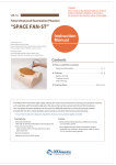
Patient Environmental Devices
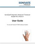
Figure 2-1.
AprovedDcumnt-53068210TPH_r4.pdfage8o39
SethGEHCMyworkspmdinaufc.
Stae:RELA-DocumnisrldfChg.bj/OP
LOGIQ 100 PRO Basic User Manual
Direction 5306802-100 Rev.4
Patient Environmental Devices
2-25
Safety
Patient Environmental Devices (continued)
1. Brightness Control: This control adjusts the brightness of the
display to the operator interface
2. Contrast Control: This control adjusts the contrast of the
display to the operator interface
3. Power On/Off(I/O): Use to turn On/Off the Main AC power to
the system.
4. Monitor: It displays the image and scan parameter data.
5. Handle: Use to aid in the movement of the system.
6. Gel Holder: Use to hold gel bottle when the L100 system is
being moved.
7. Probe Holder: The probe can be stored in the probe holder,
when not in use.
8. Probe Connector: connects the probe to the system
9. Keyboard: Used for patient data entry, and to change scan
parameter for image annotation, VCR controld and selection
of various function menus.
10. Video in: Enables an External signal (VCR play back)
11. Shutter: Connects the Video graphic printer for remote
operation.
12. Foot Switch: An optional foot Switch is provided as an
accessory to be used in parallel with or as an alternative to
the Freeze key.Enables the foot switch to freeze a real time
image.
13. Video Out: Enables the connection of a video signal to
external equipment Video graphic printer,VCR recording
14. Power Socket:Connects the main AC input
15. Circuit Breaker: The circuit breaker automatically shuts off
power to the system in case power over load.
16. USB Port: Used for printer and image transfer to USB Flash
Drive.
AprovedDcumnt-53068210TPH_r4.pdfage9o3
SethGEHCMyworkspmdinaufc.
Stae:RELA-DocumnisrldfChg.bj/OP
2-26
LOGIQ 100 PRO Basic User Manual
Direction 5306802-100 Rev.4
Safety Precautions
Acceptable Devices
The Patient Environmental devices shown on the previous page
are specified to be suitable for use within the PATIENT
ENVIRONMENT.
CAUTION
DO NOT connect any probes or accessories without approval
by GE within the PATIENT ENVIRONMENT.
See ‘Peripheral Update for EC countries’ on page 2-21 for
more information.
Unapproved Devices
CAUTION
DO NOT use unapproved devices.
If devices are connected without the approval of GE, the
warranty will be INVALID.
Any device connected to the LOGIQ 100 PRO must conform to
one or more of the requirements listed below:
1. IEC standard or equivalent standards appropriate to
devices.
2. The devices shall be connected to PROTECTIVE EARTH
(GROUND).
Accessories, Options, Supplies
CAUTION
Unsafe operation or malfunction may result. Use only the
accessories, options and supplies approved or recommended
in these instructions for use.
AprovedDcumnt-53068210TPH_r4.pdfage5o39
SethGEHCMyworkspmdinaufc.
Stae:RELA-DocumnisrldfChg.bj/OP
LOGIQ 100 PRO Basic User Manual
Direction 5306802-100 Rev.4
2-27
Safety
Warning Label Location
Figure 2-2.
AprovedDcumnt-53068210TPH_r4.pdfage51of349
SethGEHCMyworkspmdinaufc.
Stae:RELA-DocumnisrldfChg.bj/OP
2-28
Label Location
LOGIQ 100 PRO Basic User Manual
Direction 5306802-100 Rev.4
Safety Precautions
Warning Label Location (continued)
Figure 2-3. RoHS Label
Figure 2-4.
WEEE Caution Label
Figure 2-5.
AprovedDcumnt-53068210TPH_r4.pdfage52o39
SethGEHCMyworkspmdinaufc.
Stae:RELA-DocumnisrldfChg.bj/OP
LOGIQ 100 PRO Basic User Manual
Direction 5306802-100 Rev.4
ESD Label
2-29
Safety
Warning Label Location (continued)
Figure 2-6.
AprovedDcumnt-53068210TPH_r4.pdfage53o9
SethGEHCMyworkspmdinaufc.
Stae:RELA-DocumnisrldfChg.bj/OP
2-30
Warning Label
LOGIQ 100 PRO Basic User Manual
Direction 5306802-100 Rev.4
Safety Precautions
Warning Label Location (continued)
Figure 2-7.
Figure 2-8.
AprovedDcumnt-53068210TPH_r4.pdfage5o39
SethGEHCMyworkspmdinaufc.
Stae:RELA-DocumnisrldfChg.bj/OP
LOGIQ 100 PRO Basic User Manual
Direction 5306802-100 Rev.4
Caution Label
Rating Plate Label
2-31
Safety
Warning Label Location (continued)
Figure 2-9.
Figure 2-10.
AprovedDcumnt-53068210TPH_r4.pdfage5o39
SethGEHCMyworkspmdinaufc.
Stae:RELA-DocumnisrldfChg.bj/OP
2-32
TUV Label
Danger/Caution Label
LOGIQ 100 PRO Basic User Manual
Direction 5306802-100 Rev.4
Safety Precautions
Warning Label Location (continued)
Figure 2-11.
Figure 2-12.
AprovedDcumnt-53068210TPH_r4.pdfage56o39
SethGEHCMyworkspmdinaufc.
Stae:RELA-DocumnisrldfChg.bj/OP
LOGIQ 100 PRO Basic User Manual
Direction 5306802-100 Rev.4
Gost Label
CISPR Label
2-33
Safety
Warning Label Location (continued)
L1(Figure 2-3)
Rohs Label (China Only).
L2(Figure 2-4)
WEEE Label: This symbol indicates that the waste
of electrical and electronic equipment must not be
disposed as unsorted municipal waste and must be
collected separately. Please contact an authorized
representative of the manufacturer for information
concerning the decommissioning of your
equipment.
L3(Figure 2-5)
ESD Label.
L4(Figure 2-6)
Warning Label: Possible shock hazard. Do not
remove covers or panels. No user serviceable parts
are inside. Refer servicing to qualified service
personnel.
L5(Figure 2-7)
Do not use the following devices near this
equipment: cellular phone, radio receiver, mobile
radio transmitter, radio controlled toy, etc. Use of
these devices near this equipment could cause this
equipment to perform outside the
publishedspecifications. Keep power to these
devices turned off when near this equipment.
AprovedDcumnt-53068210TPH_r4.pdfage57o39
SethGEHCMyworkspmdinaufc.
Stae:RELA-DocumnisrldfChg.bj/OP
2-34
L6(Figure 2-8)
Rating Plate Label.
L7(Figure 2-9)
TUV Label: TUV Listing and Certification Mark is
used to designate conformance to nationally
recognized product safety standards. The Mark
bears the name and/or logo of the testing laboratory,
product category, safety standard to which
conformity is assessed, and a control number
L8(Figure 2-10)
Danger/Caution Label: Prescription Device: United
States law restricts this device to sale or use by or
on the order of a physicians U.S.A. Only
L9(Figure 2-11)
Gost Label (Russia Only).
L10(Figure 2-12)
The CE Mark of Conformity indicates this equipment
conforms with the Council Directive 93/42/EEC
CISPR CAUTION: The LOGIQ 100 PRO conforms
to the CISPR11, Group 1, Class A of the
international standard for Electromagnetic
disturbance characteristics.
LOGIQ 100 PRO Basic User Manual
Direction 5306802-100 Rev.4
Chapter 3
Preparing the System for Use
Describes the site requirements, console overview,
system positioning/transporting, powering on the
system, adjusting the display monitor, probes and
operator controls.
AprovedDcumnt-53068210TPH_r4.pdfage58o39
SethGEHCMyworkspmdinaufc.
Stae:RELA-DocumnisrldfChg.bj/OP
LOGIQ 100 PRO Basic User Manual
Direction 5306802-100 Rev.4
3-1
Preparing the System for Use
Preparing The System For Use
Introduction
NOTE:
Only qualified physicians or sonographers should perform
ultrasound scanning on human subjects for medical diagnostic
reasons. Request training, if needed.
Do not attempt to install the system alone. General Electric,
Affiliate, or Distributor Field Engineers and Application
Specialists will install and setup the system. See ‘Contact
Information’ on page 1-5 for more information.
The LOGIQ 100 PRO does not contain any operator serviceable
internal components. Ensure that unauthorized personnel do not
tamper with the unit.
Perform regular preventive maintenance. See ‘System Care and
Maintenance’ on page 15-10 for more information.
Maintain a clean environment. Turn off, and if possible,
disconnect the system before cleaning the unit. See ‘System
Care and Maintenance’ on page 15-10 for more information.
Never set liquids on the unit to ensure that liquid does not drip
into the control panel or unit.
AprovedDcumnt-53068210TPH_r4.pdfage59o3
SethGEHCMyworkspmdinaufc.
Stae:RELA-DocumnisrldfChg.bj/OP
3-2
LOGIQ 100 PRO Basic User Manual
Direction 5306802-100 Rev.4
Preparing The System For Use
Before the system arrives
NOTICE
This medical equipment is approved, in terms of the prevention
of radio wave interference, to be used in hospitals, clinics and
other institutions which are environmentally qualified. The use of
this equipment in an inappropriate environment may cause
some electronic interference to radios and televisions around
the equipment.
Ensure that the following is provided for the new system:
•
A separate power outlet with a 3 amp circuit breaker for 120
VAC (USA) or 2 amp circuit breaker for 220-240 VAC
(Europe, Latin America, and Asia).
•
Take precautions to ensure that the console is protected
from electromagnetic interference.
Precautions include:
•
Operate the console at least 15 feet away from motors,
typewriters, elevators, and other sources of strong
electromagnetic radiation.
•
Operation in an enclosed area (wood, plaster or
concrete walls, floors and ceilings) helps prevent
electromagnetic interference.
•
Special shielding may be required if the console is to be
operated in the vicinity of radio broadcast equipment.
In order to properly install the system, certain hardware must be
in place and operational within the room where the console is
used.
AprovedDcumnt-53068210TPH_r4.pdfage6o39
SethGEHCMyworkspmdinaufc.
Stae:RELA-DocumnisrldfChg.bj/OP
LOGIQ 100 PRO Basic User Manual
Direction 5306802-100 Rev.4
3-3
Preparing the System for Use
Environmental Requirements
The system should be operated, stored, or transported within
the parameters outlined below. Either its operational
environment must be constantly maintained or the unit must be
turned off.
NOTE:
You may get an overheating message with regard to fan speed.
Ensure adequate system/room ventilation.
Table 3-1:
Operational
Storage
Transport (<16hrs.)
10 - 40 degrees C
10 - 60 degrees C
-40 - 60 degrees C
50 - 104 degrees F
14 - 140 degrees F
-40 - 140 degrees F
Humidity
30 - 75%
non-condensing
30 - 90%
non-condensing
30 - 90%
non-condensing
Pressure
700 - 1060hPa
700 - 1060hPa
700 - 1060hPa
Temperature
SethGEHCMyworkspmdinaufc.
Stae:RELA-DocumnisrldfChg.bj/OP
3-4
AprovedDcumnt-53068210TPH_r4.pdfage61of349
System Environmental Requirements
LOGIQ 100 PRO Basic User Manual
Direction 5306802-100 Rev.4
System Overview
System Overview
System Graphics
The following are illustrations of the console:
Figure 3-1.
LOGIQ 100 PRO System
1. Brightness Rotary
2. Contrast Rotary
3. Power On/Off Switch
4. Monitor
5. Handle
6. Gel Holder
7. Probe Holder
8. Probe Connector
9. keyboard
10. Rear Panel
11. Cable Hook
AprovedDcumnt-53068210TPH_r4.pdfage62o39
SethGEHCMyworkspmdinaufc.
Stae:RELA-DocumnisrldfChg.bj/OP
LOGIQ 100 PRO Basic User Manual
Direction 5306802-100 Rev.4
3-5
Preparing the System for Use
Peripheral/Accessory Connection
Peripheral/Accessory Connector Panel
LOGIQ 100 PRO peripherals and accessories can be properly
connected using the rear connector panel located behind the
rear door.
CAUTION
Each outer (case) ground line of peripheral/accessory
connectors are Earth Grounded.
Signal ground lines are Not Isolated.
CAUTION
For compatiblity reasons, use only GE approved probes,
peripherals or accessories.
Be sure to plug the power supply cable of the peripherals to the
connector panel of the system to avoid unexpected electrical
shock.
DO NOT connect any probes or accessories without approval
by GE.
CAUTION
AprovedDcumnt-53068210TPH_r4.pdfage63o9
SethGEHCMyworkspmdinaufc.
Stae:RELA-DocumnisrldfChg.bj/OP
3-6
The connection of equipment or transmission networks other
than as specified in these instructions can result in electric
shock hazard. Alternate connections will require verification of
compatibility and conformity to IEC/EN 60601-1-1 by the
installer.
LOGIQ 100 PRO Basic User Manual
Direction 5306802-100 Rev.4
System Overview
Peripheral/Accessory Connector Panel (continued)
Figure 3-2.
Rear Panel Connectors
1. Power Connector - for the power cord.
2. Foot Switch - connects optional foot switch.
3. Shutter - connects the VGP for remote operation.
4. Video in - Enables an external signal (VCR play back).
5. Video Out - Enables the connection of a video signal to
external equipment Video graphic printer, VCR recording.
6. Thermal Circuit Breaker - The circuit breaker automatically
shuts off power to the system in case power over load.
7. USB Port - diagnose the status of hardware boards
connected to the system.
AprovedDcumnt-53068210TPH_r4.pdfage6o39
SethGEHCMyworkspmdinaufc.
Stae:RELA-DocumnisrldfChg.bj/OP
LOGIQ 100 PRO Basic User Manual
Direction 5306802-100 Rev.4
3-7
Preparing the System for Use
Footswitch (Option)
Use only the recommended optional multi-functional footswitch.
Figure 3-3.
Footswitch
The foot switch, which is the remote FREEZE device, is
connected to the rear panel of the system.
This extra FREEZE switch is provided to enhance flexibility to
freeze image.
AprovedDcumnt-53068210TPH_r4.pdfage65o39
SethGEHCMyworkspmdinaufc.
Stae:RELA-DocumnisrldfChg.bj/OP
3-8
LOGIQ 100 PRO Basic User Manual
Direction 5306802-100 Rev.4
System Overview
Two Probe Port (Option)
Use only the recommended optional two probe port.
Figure 3-4.
1. Probe Lock
2. Probe Connector1
3. Probe Connector2
Two Probe Probe connector
4. LED
5. Probe Change Switch
6. Two probe port connector
The two probe port is an option that serves as an interface to
attach two probes to the single probe capable LOGIQ 100 PRO
system. It enables users to switch between probes without
disconnecting the probes.
The two probe port module can be connected or disconnected at
any time regardless of whether the system is powered ON or
OFF.
AprovedDcumnt-53068210TPH_r4.pdfage6o39
SethGEHCMyworkspmdinaufc.
Stae:RELA-DocumnisrldfChg.bj/OP
LOGIQ 100 PRO Basic User Manual
Direction 5306802-100 Rev.4
3-9
Preparing the System for Use
Two Probe Port (Option) (continued)
Follow the below instructions to attach two probe port:
•
Remove the probe from the probe connector if any
connected.
•
Lift the probe holder vertically.
•
Align the two probe connector with the system port and
carefully push in place.
•
Lock the two probe port by turning probe port lock in to 3 ‘O’
clock position.
•
Replace the probe holder correctly.
•
Connect the two probes in to the two probe connectors.
Actiavting the probe
To activate the probe:
AprovedDcumnt-53068210TPH_r4.pdfage67o39
SethGEHCMyworkspmdinaufc.
Stae:RELA-DocumnisrldfChg.bj/OP
3-10
•
Press the Probe change switch on the two probe port to
toggle between the two connected probes.
•
The appropriate probe is activated and The LED toggles to
indicate the probe change.
LOGIQ 100 PRO Basic User Manual
Direction 5306802-100 Rev.4
System Overview
L200 Probe Adapter (Option)
Use only the recommended optional L200 probe adapter.
Figure 3-5.
L200 Probe Adapter
1. Probe Lock
2. Probe Connector
3. L200 Probe Connector
The L200 Probe Adapter is an option that serves as an interface
to attach L200 probes to the LOGIQ 100 PRO system.
Follow the below instructions to attach L200 probe adapter:
•
Remove the probe from the probe connector if any
connected.
•
Lift the probe holder vertically.
•
Align the L200 probe adapter with the system port and
carefully push in place.
•
Lock the two probe port by turning probe port lock in to 3 ‘O’
clock position.
•
Replace the probe holder correctly.
AprovedDcumnt-53068210TPH_r4.pdfage68o39
SethGEHCMyworkspmdinaufc.
Stae:RELA-DocumnisrldfChg.bj/OP
LOGIQ 100 PRO Basic User Manual
Direction 5306802-100 Rev.4
3-11
Preparing the System for Use
System Positioning/Transporting
Moving the System
When moving or transporting the system, follow the precautions
below to ensure the maximum safety for personnel, the system,
and other equipment.
Before moving the system
1. Press the Power On/Off switch to power off. See ‘Power
On’ on page 3-19 for more information.
2. Unplug the power cord.
3. All cables from off-board peripheral devices (external
printer, external hard drive, etc.) must be disconnected from
the console.
4. Disconnect the footswitch from the console.
5. Ensure that no loose items are left on the console.
6. Wind the power cable around cable hooks located on the
rear panel.
AprovedDcumnt-53068210TPH_r4.pdfage69o3
SethGEHCMyworkspmdinaufc.
Stae:RELA-DocumnisrldfChg.bj/OP
3-12
LOGIQ 100 PRO Basic User Manual
Direction 5306802-100 Rev.4
System Positioning/Transporting
Before moving the system (continued)
To prevent damage to the Power Cord, DO NOT pull
excessively on the cord or make sharp bends while
wrapping.
Figure 3-6.
Location of hook
a. Hook
AprovedDcumnt-53068210TPH_r4.pdfage7o39
SethGEHCMyworkspmdinaufc.
Stae:RELA-DocumnisrldfChg.bj/OP
LOGIQ 100 PRO Basic User Manual
Direction 5306802-100 Rev.4
3-13
Preparing the System for Use
Before moving the system (continued)
7. Connect all probes to be used while off site.
NOTE:
If more than two (2) probes are intended to be used, store
the additional probes securely.
8. Store all other probes in their original cases or in soft cloth
or foam to prevent damage.
9. Store sufficient gel and other essential accessories in the
provided space.
AprovedDcumnt-53068210TPH_r4.pdfage71of349
SethGEHCMyworkspmdinaufc.
Stae:RELA-DocumnisrldfChg.bj/OP
3-14
LOGIQ 100 PRO Basic User Manual
Direction 5306802-100 Rev.4
System Positioning/Transporting
Transporting the System
Use extra care when transporting the system using vehicles. In
addition to the instructions used when moving the system (See
‘Moving the System’ on page 3-12 for more information.), also
perform the following:
1. Keep the unit up right.
2. Prevent vibration damage by driving cautiously. Avoid
unpaved roads, excessive speeds, and erratic stops or
starts.
AprovedDcumnt-53068210TPH_r4.pdfage72o39
SethGEHCMyworkspmdinaufc.
Stae:RELA-DocumnisrldfChg.bj/OP
LOGIQ 100 PRO Basic User Manual
Direction 5306802-100 Rev.4
3-15
Preparing the System for Use
Powering the System
Connecting and Using The System
To connect the system to the electrical supply:
1. Ensure that the wall outlet is of the appropriate type.
2. Ensure that the power switch is turned off.
3. Unwrap the power cable. Make sure to allow sufficient slack
in the cable so that the plug is not pulled out of the wall if the
system is moved slightly.
CAUTION
Use the appropriate power cord provided by or designated
by GE Healthcare.
4. Attach the power plug to the system and secure it in place
by using the retaining clamp.
5. Push the power plug securely into the wall outlet.
CAUTION
Use caution to ensure that the power cable does not
disconnect during system use.
If the system is accidentally unplugged, data may be lost.
AprovedDcumnt-53068210TPH_r4.pdfage73o9
SethGEHCMyworkspmdinaufc.
Stae:RELA-DocumnisrldfChg.bj/OP
3-16
LOGIQ 100 PRO Basic User Manual
Direction 5306802-100 Rev.4
Powering the System
Connecting and Using The System (continued)
WARNING
To avoid risk of fire, the system power must be supplied from a
separate, properly rated outlet. See ‘Before the system arrives’
on page 3-3 for more information.
Under no circumstances should the AC power plug be altered,
changed, or adapted to a configuration rated less than
specified. Never use an extension cord or adapter plug.
To help assure grounding reliability, connect to a “hospital
grade” or “hospital only” grounded power outlet.
Figure 3-7.
Example Plug and Outlet Configurations
1. 100 -120 VAC
2. 220-240 VAC
AprovedDcumnt-53068210TPH_r4.pdfage7o39
SethGEHCMyworkspmdinaufc.
Stae:RELA-DocumnisrldfChg.bj/OP
LOGIQ 100 PRO Basic User Manual
Direction 5306802-100 Rev.4
3-17
Preparing the System for Use
Acclimation Time
After being transported, the unit requires one hour for each 2.5
degree increment its temperature is below 10 degree C or above
40 degree C.
SethGEHCMyworkspmdinaufc.
Stae:RELA-DocumnisrldfChg.bj/OP
System Acclimation Time Chart
Degree C
60
55
50
45
40
35
30
25
20
15
10
Degree F
140
131
122
113
104
95
86
77
68
59
50
hours
8
6
4
2
0
0
0
0
0
0
0
Degree C
5
0
-5
-10
-15
-20
-25
-30
-35
-40
Degree F
41
32
23
14
5
-4
-13
-22
-31
-40
hours
2
4
6
8
10
12
14
16
18
20
3-18
AprovedDcumnt-53068210TPH_r4.pdfage75o39
Table 3-2:
LOGIQ 100 PRO Basic User Manual
Direction 5306802-100 Rev.4
Powering the System
Power On
Press the Power On/Off switch to turn the power on. The circuit
breaker must also be in the on position. For circuit breaker
location, See ‘Circuit Breaker’ on page 3-22 for more
information.
Figure 3-8.
Power On/Off Location
a. Power On/Off Switch
AprovedDcumnt-53068210TPH_r4.pdfage76o39
SethGEHCMyworkspmdinaufc.
Stae:RELA-DocumnisrldfChg.bj/OP
LOGIQ 100 PRO Basic User Manual
Direction 5306802-100 Rev.4
3-19
Preparing the System for Use
Power Up Sequence
The system is initialized. During this time:
•
The system boots up and the status is reflected on the
monitor.
Figure 3-9.
If problems occur, freeze the image and take a picture for
reference. This will help if there is a need to call for service.
HINTS
•
NOTE:
Power Up Graphic Sequence
Probes are initialized for immediate operation.
If no probe is connected, the system goes into freeze mode.
After initialization is complete, all lighted buttons on the Control
Panel light and the default B-Mode screen is displayed in the
monitor display.
AprovedDcumnt-53068210TPH_r4.pdfage7o39
SethGEHCMyworkspmdinaufc.
Stae:RELA-DocumnisrldfChg.bj/OP
3-20
LOGIQ 100 PRO Basic User Manual
Direction 5306802-100 Rev.4
Powering the System
Power Off
To power off the system:
1. To shutdown the system, press the Power On/Off switch at
the front of the system for 5 to 6 seconds.
2. Disconnect the probes.
Clean or disinfect all probes as necessary. Store them in
their shipping cases to avoid damage.
3. If daily maintenance is to be performed, turn off the circuit
breaker.
NOTE:
Do not pull the power cable without turning off the circuit
breaker. For circuit breaker location, See ‘Circuit Breaker’
on page 3-22 for more information.
AprovedDcumnt-53068210TPH_r4.pdfage78o39
SethGEHCMyworkspmdinaufc.
Stae:RELA-DocumnisrldfChg.bj/OP
LOGIQ 100 PRO Basic User Manual
Direction 5306802-100 Rev.4
3-21
Preparing the System for Use
Circuit Breaker
The Circuit Breaker is located at the rear panel of the system.
On supplies main power to all internal systems. Off removes
main power from all internal systems. The circuit breaker
automatically shuts off power to the system in case of a power
overload.
If a power overload occurs:
1. Turn off all peripheral devices.
2. Switch OFF the main power switch to the console.
3. Reactivate the Circuit Breaker switch.
NOTE:
If the Circuit Breaker switch does not remain in the On position
or trips again:
1. Disconnect the power cord.
2. Call Service immediately
DO NOT attempt to use the system.
Figure 3-10.
Circuit Breaker Location
a. Circuit Breaker
b. Power Connector
AprovedDcumnt-53068210TPH_r4.pdfage79o3
SethGEHCMyworkspmdinaufc.
Stae:RELA-DocumnisrldfChg.bj/OP
3-22
LOGIQ 100 PRO Basic User Manual
Direction 5306802-100 Rev.4
Adjusting the Display Monitor
Adjusting the Display Monitor
Brightness and Contrast
Adjusting the monitor's contrast and brightness is one of the
most important factors for proper image quality. If these controls
are set incorrectly, the Gain, TGC, Dynamic Range and even
Power Output may have to be changed more often than
necessary to compensate.
The proper setup displays a complete gray scale. The lowest
level of black should just disappear into the background and the
highest white should be bright, but not saturated.
To adjust the brightness:
a. Turn the CONTRAST Rotary pot,which is positioned on
the inclined face of the front panel,clockwise or
counterclockwise to get a sharp image and a complete
range of gray shades.The lowest level of block should
just disappear into the background and highest white
should be bright but not saturated.
b. Similarly,turn the BRIGHTNESS Rotary pot,Which is
Positioned above the contrast rotary Pot,Clockwise or
Counter clockwise to increase the brightness until the
background is just one shade above black.
Figure 3-11.
AprovedDcumnt-53068210TPH_r4.pdfage8o39
SethGEHCMyworkspmdinaufc.
Stae:RELA-DocumnisrldfChg.bj/OP
LOGIQ 100 PRO Basic User Manual
Direction 5306802-100 Rev.4
Monitor Screen
3-23
Preparing the System for Use
Probes
Introduction
Use Only approved probes. All Imaging probes can be plugged
into any of the two standard probe port. Probes can be
connected or disconnected from the system at any time
regardless of whether the LOGIQ 100 PRO system is powered
ON/OFF.
Connecting a Probe
Probes can be connected at any time, regardless of whether the
console is powered on or off. To ensure that the ports are not
active, place the system in the image freeze condition.
To connect a probe:
1. Place the probe’s carrying case on a stable surface and
open the case.
2. Carefully remove the probe and unwrap the probe cord.
3. DO NOT allow the probe head to hang free. Impact to the
probe head could result in irreparable damage. Use the
integrated cable management hook to wrap the cord.
Inspect the probe before and after each use for damage or
degradation to the housing, strain relief, lens, seal and
connector. DO NOT use a transducer which appears
damaged until functional and safe performance is verified. A
thorough inspection should be conducted during the
cleaning process.
AprovedDcumnt-53068210TPH_r4.pdfage81of349
SethGEHCMyworkspmdinaufc.
Stae:RELA-DocumnisrldfChg.bj/OP
3-24
LOGIQ 100 PRO Basic User Manual
Direction 5306802-100 Rev.4
Probes
Connecting a Probe (continued)
4. Turn the connector locking handle counterclockwise.
5. Align the connector with the probe port and carefully push
into place.
Before inserting the connector into the probe port, inspect
the probe connector pin. If the pin is bent, do not use the
probe until it has been inspected and repaired/replaced by a
GE Service Representative.
6. Turn the connector locking handle clockwise to secure the
probe connector.
7. Carefully position the probe cord so that it is free to move
and is not resting on the floor
8. When the probe is connected, it is automatically activated.
Cable Handling
Take the following precautions with probe cables:
•
Do not bend the cable acutely
•
Avoid crossing cables between probes.
AprovedDcumnt-53068210TPH_r4.pdfage82o39
SethGEHCMyworkspmdinaufc.
Stae:RELA-DocumnisrldfChg.bj/OP
LOGIQ 100 PRO Basic User Manual
Direction 5306802-100 Rev.4
3-25
Preparing the System for Use
Disconnecting a Probe
Probes can be disconnected at any time. However, the probe
should not be active when disconnecting the probe.
To disconnect a probe:
1. Ensure the probe is deactivated. Deactivate by selecting
another probe or pressing Freeze.
2. Move the probe locking handle counterclockwise.
3. Pull the probe and connector straight out of the probe port.
4. Carefully slide the probe and probe connector away from
the probe port and around the right side of the keyboard.
5. Ensure the cable is free.
6. Be sure that the probe head is clean before placing the
probe in its storage box or a wall hanging unit.
Storing the Probe
It is recommended that all probes be stored in the provided
carrying case or in the wall rack designed for probe storage.
Carrying case:
AprovedDcumnt-53068210TPH_r4.pdfage83o9
SethGEHCMyworkspmdinaufc.
Stae:RELA-DocumnisrldfChg.bj/OP
3-26
•
First place the probe connector into the carrying case.
•
Carefully wind the cable into the carrying case.
•
Carefully place the probe head into the carrying case. DO
NOT use excessive force or impact the probe head.
LOGIQ 100 PRO Basic User Manual
Direction 5306802-100 Rev.4
Operator Controls
Operator Controls
Operator Panel Map
Controls are grouped together by function for ease of use. See
the callouts for this figure on the following page.
Figure 3-12.
AprovedDcumnt-53068210TPH_r4.pdfage8o39
SethGEHCMyworkspmdinaufc.
Stae:RELA-DocumnisrldfChg.bj/OP
LOGIQ 100 PRO Basic User Manual
Direction 5306802-100 Rev.4
Operator Panel
3-27
Preparing the System for Use
Operator Panel Map (continued)
1. Function Keys (New Patient, ID/Name,
Comment, and Preset)
2. TGC
3. Measurement Keys
4. Auto, Zoom keys
5. Gain/Cine Control
6.
7.
8.
9.
10.
Imaging keys.
Freeze Key
Record Key
Archive Keys
External Video
Function Keys
Patient
WARNING
SethGEHCMyworkspmdinaufc.
Stae:RELA-DocumnisrldfChg.bj/OP
To avoid patient identification errors, always verify the
identification with the patient. Make sure the correct patient
identification appears on all screens and hard copy prints.
ID/Name
Pressing ID/NAME allows modification of patient data without
erasing patient image, measurements, calculations and
summary reports.
Comment
The Comment key enables the image text editor. Use the
Trackball and Spacebar to move the cursor.
PRESET
Press PRESET to select the default scan parameters stored for
the probe connected. Parameter scan be predefined using the
Control-W function.
3-28
AprovedDcumnt-53068210TPH_r4.pdfage85o39
Enters Patient screen.
LOGIQ 100 PRO Basic User Manual
Direction 5306802-100 Rev.4
Operator Controls
Mode, Display and Record
Gain
The GAIN/ROTATE knob adjusts the amplification of the
returning echoes in both B and M–Modes.
When the image is frozen, this knob activates the cine memory
and can be used to move around the cine gauge. When the
image is frozen and ‘body pattern’ is selected it rotates the probe
marker for body pattern
TGC Controls
Used to vary the gain of the received echoes at a specific depth.
B-Mode
Activates B-Mode format.
M-Mode
Toggles between B/M and M-Mode formats.
Dual B-Mode
During dual display modes the L and R keys activate the Left or
Right displayed image.
ATO (AO)
Used to optimize the tissue images in image scan area.
Zoom
Zoom is used to enlarge the ROI (Region Of Interest) of the
image.
AprovedDcumnt-53068210TPH_r4.pdfage86o39
SethGEHCMyworkspmdinaufc.
Stae:RELA-DocumnisrldfChg.bj/OP
LOGIQ 100 PRO Basic User Manual
Direction 5306802-100 Rev.4
3-29
Preparing the System for Use
Mode, Display and Record (continued)
Reverse
The Reverse key toggles the left/right orientation of the scan
image.
Freeze
The Freeze key is used to stop the acquisition of ultrasound
data and freeze the image in system memory. Pressing Freeze
a second time continues live image data acquisition.
Dynamic Range
DYNAMIC RANGE adjusts the intensities of returning echoes.
Scroll Key
Scroll enables scrolling the live image Left/Right, Up/Down on
the BMode Format.
Body Pattern
Press Body Pattern to select a body pattern from the currently
active body pattern package.
Pressing the Body Pattern key at the end of each menu (Either
Abdomen/Urology/SP/CD or OB/GYN) takes you to the next
Body Pattern Package automatically.
AprovedDcumnt-53068210TPH_r4.pdfage87o39
SethGEHCMyworkspmdinaufc.
Stae:RELA-DocumnisrldfChg.bj/OP
3-30
LOGIQ 100 PRO Basic User Manual
Direction 5306802-100 Rev.4
Operator Controls
Mode, Display and Record (continued)
External Video
EXTERNAL VIDEO enables an external video signal (VCR
playback) to be viewed on the LOGIQ 100 PRO system monitor.
Back Space
BACK SPACE erases individual characters to the left of the
cursor while entering alphanumeric information.
Record Key
RECORD prints the images or report pages on Video Graphic
Printer.
Return Key
Return Key moves the cursor next line or next field.
Control/Enter Key
CONTROL/ENTER activates all control functions.
Store Key
STORE key stores the images.
Recall Key
RECALL key recalls the stored images.
AprovedDcumnt-53068210TPH_r4.pdfage8o39
SethGEHCMyworkspmdinaufc.
Stae:RELA-DocumnisrldfChg.bj/OP
LOGIQ 100 PRO Basic User Manual
Direction 5306802-100 Rev.4
3-31
Preparing the System for Use
Measurement and Annotation
Clear
The Clear key is generally used to erase functions, such as
annotations/comments, body patterns and measurements.
Pressing the Clear key again exits the selected function.
Measurement
The Measure key is used in all types of basic measurements. It
also becomes the “mouse” arrow for making selections along
with the Set key (to fix or finish a selection). When the Measure
key is pressed, the measurement is displayed.
Depth Key
The Depth controls the image display depth.
Focus Key
FOCUS enables the selection of the optimal focal depth for
transmit.
Set
The Set key is used for various functions, but is generally used
to fix or finish an operation (e.g. to fix a measurement caliper).
Trackball
The Trackball is used with almost every key function in this
group. Trackball control depends on the last key function
pressed.
AprovedDcumnt-53068210TPH_r4.pdfage89o3
SethGEHCMyworkspmdinaufc.
Stae:RELA-DocumnisrldfChg.bj/OP
3-32
LOGIQ 100 PRO Basic User Manual
Direction 5306802-100 Rev.4
Image Display
Image Display
Overview
The LOGIQ 100 PRO system offers a variety of display formats.
Each format shows the operator valuable information relating to
patient data and system scan parameters.
Figure 3-13.
AprovedDcumnt-53068210TPH_r4.pdfage9o3
SethGEHCMyworkspmdinaufc.
Stae:RELA-DocumnisrldfChg.bj/OP
LOGIQ 100 PRO Basic User Manual
Direction 5306802-100 Rev.4
Monitor Display
3-33
Preparing the System for Use
Image Display (continued)
1.
2.
3.
4.
5.
6.
7.
8.
9.
AprovedDcumnt-53068210TPH_r4.pdfage91of349
SethGEHCMyworkspmdinaufc.
Stae:RELA-DocumnisrldfChg.bj/OP
3-34
Institution/Hospital Name
Image Archive Information.
Patient ID.
Patient Name.
Date.
Time.
Probe.
Biopsy.
Gray Bar.
10.
11.
12.
13.
14.
15.
16.
17.
18.
Cine Status.
Body Pattern.
Calculation Area.
Gain.
Dynamic Range.
Depth.
Print out status.
Main Menu.
Archive Memory Status.
LOGIQ 100 PRO Basic User Manual
Direction 5306802-100 Rev.4
Chapter 4
Preparing for an Exam
Describes how to begin an exam.
AprovedDcumnt-53068210TPH_r4.pdfage92o3
SethGEHCMyworkspmdinaufc.
Stae:RELA-DocumnisrldfChg.bj/OP
LOGIQ 100 PRO Basic User Manual
Direction 5306802-100 Rev.4
4-1
Preparing for an Exam
Beginning an Exam
Introduction
Begin an exam by entering new patient information.
The operator should enter as much information as possible,
such as:
1. Patient ID
2. Patient Name
The patient's name and ID number is retained with each
patient's image and transferred with each image during
archiving or hard copy printing.
CAUTION
AprovedDcumnt-53068210TPH_r4.pdfage93o
SethGEHCMyworkspmdinaufc.
Stae:RELA-DocumnisrldfChg.bj/OP
4-2
To avoid patient identification errors, always verify the
identification with the patient. Make sure the correct patient
identification appears on all screens and hard copy prints.
LOGIQ 100 PRO Basic User Manual
Direction 5306802-100 Rev.4
Beginning an Exam
Beginning a New Patient
Figure 4-1.
Patient Entry Menu
Pressing the Patient key on the Operator Panel displays the
Patient screen on the monitor.
•
Enter Patient Identification (16 characters) using
alphanumeric keys,
•
Press RETURN to go to the Patient Name field (28
characters).
Enter Patient Name.
•
Press RETURN or NEW PATIENT to register the inputs and
exit out of the menu (or)
Press CLEAR to exit NEW PATIENT and abort entry if
required.
NOTE:
To modify only Patient Information with out erasing other data,
Press the ID/NAME key. Pressing ID/NAME allows modification
of patient data without erasing patient image, measurements,
calculations, and summary reports.
Exam Category Selection
Select from 7 exam application categories:Abdomen, Obstetrics,
Gynecology, Cardiology, Urology, Small Parts, and User
Defined.
AprovedDcumnt-53068210TPH_r4.pdfage9o3
SethGEHCMyworkspmdinaufc.
Stae:RELA-DocumnisrldfChg.bj/OP
LOGIQ 100 PRO Basic User Manual
Direction 5306802-100 Rev.4
4-3
Preparing for an Exam
Exam Category Selection (continued)
The Exam Category can be selected using the CONTROL D.
Follow the below instructions to select any one of available
exam categories.
•
Press “Control” D.
•
Select any of the following options.
•
•
1 for abdomen
•
2 for Obstetrics
•
3 for Gynecology
•
4 for Cardiology
•
5 for Urology
•
6 for Small Parts
•
7 for User Defined
Press “Control” key to invoke selected exam category.
Figure 4-2.
AprovedDcumnt-53068210TPH_r4.pdfage95o3
SethGEHCMyworkspmdinaufc.
Stae:RELA-DocumnisrldfChg.bj/OP
4-4
Exam Category Selection
LOGIQ 100 PRO Basic User Manual
Direction 5306802-100 Rev.4
Beginning an Exam
Scanning a New Patient
•
Position the patient in a lying down position and apply
Acoustic gel to the probe and on the patient. Position the
transducer on the patient, adjust the imaging controls to
produce a high quality image.
•
Begin the scan on the patient.
•
A realtime image appears on the monitor through the
following controls:
•
Orient the probe on the patient based on the study to be
performed or view to be obtained.
•
Increase or decrease the overall Gain, TGC and
Dynamic Range to obtain the desired Image quality.
•
If the image is not bright, increase the overall Gain until
the appropriate brightness is obtained. The amplitude of
returning echoes should be optimally displayed.
•
Increase Dynamic Range to get a smoother image.
•
Decrease Dynamic Range to get an image with more
contrast.
•
Position the Focus marker in the area of interest.
•
Press Freeze to stop image acquisition.
•
Refer to the General Measurements chapter for details on
making generic measurements.
•
Enter comments on the image area, if required, by pressing
the Comments key.
•
Use Record key to print the image on VGP/HP Laserjet or to
store the image permanently.
AprovedDcumnt-53068210TPH_r4.pdfage96o3
SethGEHCMyworkspmdinaufc.
Stae:RELA-DocumnisrldfChg.bj/OP
LOGIQ 100 PRO Basic User Manual
Direction 5306802-100 Rev.4
4-5
Preparing for an Exam
Helpful Hints
HINTS
If power is lost while entering new patient data, data will not be
saved.
The following rules apply when filling in data on the new patient
menu.
•
Press Caps Lock to type uppercase letters. Press Caps
Lock again to type lowercase letters.
•
Press Back Space to erase characters and correct errors.
•
Use the Trackball to move the cursor to the desired item.
•
When pressing the Set key at the EXIT field, the system
returns to B-Mode live scanning.
•
To start over, press New Patient.
NOTE: User and factory-dependent presets are dependent
upon the exam category selected when filling the new patient
menu.
AprovedDcumnt-53068210TPH_r4.pdfage97o3
SethGEHCMyworkspmdinaufc.
Stae:RELA-DocumnisrldfChg.bj/OP
4-6
LOGIQ 100 PRO Basic User Manual
Direction 5306802-100 Rev.4
Chapter 5
Optimizing the Image
Describes how to adjust the image. This chapter is
broken into the following sections: B-Mode, B/B-Mode,
B/M-Mode and M-Mode.
AprovedDcumnt-53068210TPH_r4.pdfage98o3
SethGEHCMyworkspmdinaufc.
Stae:RELA-DocumnisrldfChg.bj/OP
LOGIQ 100 PRO Basic User Manual
Direction 5306802-100 Rev.4
5-1
Optimizing the Image
Optimizing B-Mode
Intended Uses
B-Mode is intended to provide two-dimensional images and
measurement capabilities concerning the anatomical structure
of soft tissue.
Figure 5-1.
AprovedDcumnt-53068210TPH_r4.pdfage9o3
SethGEHCMyworkspmdinaufc.
Stae:RELA-DocumnisrldfChg.bj/OP
5-2
B-Mode Display
LOGIQ 100 PRO Basic User Manual
Direction 5306802-100 Rev.4
Optimizing B-Mode
Typical B-Mode Exam Protocol
A typical examination using B-Mode might proceed
1. Record exam-related patient information. Verify system
configuration (probes and presets).
2. Position the patient and the console for optimum operator
and patient comfort. Perform the scan.
3. Complete the study by collecting all the data.
AprovedDcumnt-53068210TPH_r4.pdfage100of349
SethGEHCMyworkspmdinaufc.
Stae:RELA-DocumnisrldfChg.bj/OP
LOGIQ 100 PRO Basic User Manual
Direction 5306802-100 Rev.4
5-3
Optimizing the Image
B-Mode Scanning Hints
HINTS
These B-Mode controls produce the following results:
Auto Optimize: Improves imaging performance while reducing
optimization time. Available in B-Mode.
Frequency: Changes system parameters to best optimize for a
particular patient type.
Gray Map: Affects the presentation of B-Mode information.
Choose the gray map prior to making other adjustments. There
is an interdependency between gray maps, gain, and dynamic
range. If you change a map, revisit gain and dynamic range
settings.
Dynamic Range: Affects the amount of gray scale information
displayed. If you increase the gain, you may want to decrease
the Dynamic Range.
Edge Enhance: Affects the amount of border crispness.
Frame Average: Smooths the image by averaging frames.
Affects the amount of speckle reduction.
TGC: Adjust TGC to adjust Gain in specific areas.
Focus position: The best focusing is at the focal zone
location. Put focal zone(s) at the area of interest. Be conscious
of where the focal zones are. Focal zones must be moved to
track at the center of the anatomy of interest.
Image Softner: Image softner brings out the differences on the
image by softening the gray scale..
AprovedDcumnt-53068210TPH_r4.pdfage101of349
SethGEHCMyworkspmdinaufc.
Stae:RELA-DocumnisrldfChg.bj/OP
5-4
LOGIQ 100 PRO Basic User Manual
Direction 5306802-100 Rev.4
Optimizing B-Mode
Depth
Description
Depth controls the distance over which the B-Mode images
anatomy. To visualize deeper structures, increase the depth. If
there is a large part of the display which is unused at the bottom,
decrease the depth.
Adjusting
Each adjustment cycles you to the next Depth setting. Imaging
and display parameters adjust automatically.
To increase/decrease, adjust Depth.
Values
Depth increments vary by probe and application. Depth displays
on the monitor in centimeters.
Benefits
Depth adjusts your field of view. It increases your field of view to
look at larger or deeper structures; it decreases your field of
view to look at structures near the skin line.
Affect on other
controls
After adjusting the depth, you may need to adjust the TGC and
focus.
Changing Depth,
HINTS
•
Clears Cine memory.
•
Erases realtime calculations graphics on the display (but not
the completed results on the worksheet page).
Make sure enough space is left below the anatomy of interest
to demonstrate shadowing or enhancement.
AprovedDcumnt-53068210TPH_r4.pdfage102of349
SethGEHCMyworkspmdinaufc.
Stae:RELA-DocumnisrldfChg.bj/OP
LOGIQ 100 PRO Basic User Manual
Direction 5306802-100 Rev.4
5-5
Optimizing the Image
Gain
Description
B-Mode Gain increases or decreases the amount of echo
information displayed in an image. It may have the effect of
brightening or darkening the image if sufficient echo information
is generated.
Adjusting
Gain values vary depending on the probe; they are not
associated with a particular position of the knob.
To decrease/increase, rotate Gain.
Values
Gain displays on the monitor in Gn (dB).
NOTE:
Benefits
Gain allows you to balance echo contrast so that cystic
structures appear echo-free and reflecting tissue fills in.
Affect on other
controls
Gain and TGC interact by adding together.
SethGEHCMyworkspmdinaufc.
Stae:RELA-DocumnisrldfChg.bj/OP
5-6
AprovedDcumnt-53068210TPH_r4.pdfage103of49
Maximum gain is factory preset to an optimum setting to
eliminate noise in the display.
LOGIQ 100 PRO Basic User Manual
Direction 5306802-100 Rev.4
Optimizing B-Mode
Focus
Description
Increases the number of focal zones or moves the focal zone(s)
so that you can tighten up the beam for a specific area. A
graphic caret corresponding to the focal zone position(s)
appears on the right edge of the image.
Adjusting
To move the focal zone to the near/far field, adjust Focus
Position.
NOTE:
Each adjustment cycles you to the next setting.
Values
Focus zone number and position vary depending on the depth,
zoom, probe, application, and frequency setting selected.
Benefits
Focus optimizes the image by increasing the resolution for a
specific area.
Affect on other
controls
Changing the focal number affects the frame rate. The greater
number of focal zones, the slower the frame rate.
AprovedDcumnt-53068210TPH_r4.pdfage104of39
SethGEHCMyworkspmdinaufc.
Stae:RELA-DocumnisrldfChg.bj/OP
LOGIQ 100 PRO Basic User Manual
Direction 5306802-100 Rev.4
5-7
Optimizing the Image
Automic Tissue Optimization (ATO)
Description
ATO lets you optimize the image based upon a specified region
of interest or anatomy within the B-Mode image in order to
improve the contrast of the displayed image data. Auto Optimize
is available in B-Mode, specifically in single or multi image, on
live images and while in zoom.
NOTE:
Adjusting
To activate/dactivate, press the AO key.
NOTE:
SethGEHCMyworkspmdinaufc.
Stae:RELA-DocumnisrldfChg.bj/OP
When ATO is active, the probe orientation marker is highlighted.
Values
Auto Optimize is active until you deactivate it.
Affect on other
controls
You may need to adjust the Gain.
5-8
AprovedDcumnt-53068210TPH_r4.pdfage105of349
Auto is not available on archived images.
LOGIQ 100 PRO Basic User Manual
Direction 5306802-100 Rev.4
Optimizing B-Mode
TGC
Description
TGC amplifies returning signals to correct for the attenuation
caused by tissues at increasing depths. TGC slide pots are
spaced proportionately to the depth. The area each pot
amplifies varies as well. A TGC curve may appear on the display
(if preset), matching the controls that you have set (except
during zoom). You can choose to deactivate the TGC curve on
the image.
Adjusting
To decrease/increase TGC, move slide pot to the left/right.
NOTE:
TGC adjusts automatically when using zoom. The TGC curve
does not change while in CINE.
Values
When you change the depth, TGC is rescaled across the new
depth range. Each pot is proportionately scaled across the
depth.
Benefits
TGC balances the image so that the density of echoes is the
same throughout the image.
Reverse
Description
Flips the image 180 degrees left/right.
Adjusting
To flip the image 180 degrees, select Reverse.
Values
The image rotates in 180 degrees left/right. Reverse settings
vary by probe and application.
Benefits
Used for anatomical correctness.
CAUTION
When reading a reverse image, be careful to observe the probe
orientation to avoid possible confusion over scan direction or
left/right image reversal.
AprovedDcumnt-53068210TPH_r4.pdfage106of349
SethGEHCMyworkspmdinaufc.
Stae:RELA-DocumnisrldfChg.bj/OP
LOGIQ 100 PRO Basic User Manual
Direction 5306802-100 Rev.4
5-9
Optimizing the Image
Inverse
Description
Flips the image 180 degrees up/down.
Adjusting
To flip the image 180 degrees up/down:
SethGEHCMyworkspmdinaufc.
•
The image rotates in 180 degrees up/down.
The image rotates in 180 degrees up/down. Invert settings vary
by probe and application.
Benefits
Used for anatomical correctness.
5-10
Stae:RELA-DocumnisrldfChg.bj/OP
Press “SHIFT” + Reverse.
Values
CAUTION
AprovedDcumnt-53068210TPH_r4.pdfage107of349
•
When reading a invert image, be careful to observe the probe
orientation to avoid possible confusion over scan direction or
up/down image inversion.
LOGIQ 100 PRO Basic User Manual
Direction 5306802-100 Rev.4
Optimizing B-Mode
Dynamic Range
Description
Dynamic Range controls how echo intensities are converted to
shades of gray, thereby increasing the adjustable range of
contrast. The Dynamic Range control name changes to
Compression on frozen images.
Adjusting
To increase/decrease, adjust Dynamic Range.
Values
The settings cycle in 6dB steps from 30 dB to 72 dB. The current
value displays. Dynamic Range values vary by probe,
application, and frequency settings.
Dynamic Range levels are returned to the factory or user preset
value when you change the following: Probe, Exam Category,
Exam Calcs, New Patient, or Multi Frequency.
Benefits
Dynamic Range is useful for optimizing tissue texture for
different anatomy. Dynamic Range should be adjusted so that
the highest amplitude edges appear as white while lowest levels
(such as blood) are just visible.
Affect on other
controls
Dynamic range operates only in realtime, not in Freeze or CINE.
It also affects Gain.
AprovedDcumnt-53068210TPH_r4.pdfage108of349
SethGEHCMyworkspmdinaufc.
Stae:RELA-DocumnisrldfChg.bj/OP
LOGIQ 100 PRO Basic User Manual
Direction 5306802-100 Rev.4
5-11
Optimizing the Image
Edge Enhance
Description
Edge Enhance brings out subtle tissue differences and
boundaries by enhancing the gray scale differences
corresponding to the edges of structures. Adjustments to MMode's edge enhancement affects the M-Mode only.
Adjusting
To cycle through settings, adjust Edge Enhance:
Figure 5-2.
•
Press “Control” I.
•
Select the intensity(0,1,2,3) of Edge Enhance.
NOTE:
By default the Edge Enhance is set to 2(Mid)
•
SethGEHCMyworkspmdinaufc.
Stae:RELA-DocumnisrldfChg.bj/OP
Press “Control” key to affect the changes.
Values
Off, Low, Med, and High. The current value displays on the .
Values vary by probe, application, and multi frequency setting.
Values are returned to the preset value when you change:
Probe, Exam Category, Exam Calcs, New Patient, or Multi
Frequency.
Benefits
Edge Enhance cleans out the B-Mode image/M-Mode timeline
by subduing some of the gray scale in order to highlight the
vessel wall or organ. This is helpful when you cannot
differentiate between the chambers of the heart.
Affect on other
controls
Edge Enhance operates in realtime only; not in Freeze or CINE.
5-12
AprovedDcumnt-53068210TPH_r4.pdfage109of34
Edge Enhance Selection
LOGIQ 100 PRO Basic User Manual
Direction 5306802-100 Rev.4
Optimizing B-Mode
Frame Average
Description
Temporal filter that averages frames together, thereby using
more pixels to make up one image. This has the effect of
presenting a smoother, softer image.
Adjusting
To adjust frame averaging, adjust Frame Average:
Figure 5-3.
•
Press “Control” A.
•
Select the average value.
•
•
0 for Frame Average off.
•
1 for 25%
•
2 for 50%
•
3 for 75%
Press “Control” key to affect the changes.
Values
Frame Average values vary by probe, application, and multi
frequency setting.
Benefits
Smooths the image.
SethGEHCMyworkspmdinaufc.
Stae:RELA-DocumnisrldfChg.bj/OP
LOGIQ 100 PRO Basic User Manual
Direction 5306802-100 Rev.4
AprovedDcumnt-53068210TPH_r4.pdfage110of349
Frame Average Selection
5-13
Optimizing the Image
Multi Frequency
Description
Multi Frequency mode lets you downshift to the probe's next
lower frequency or shift up to a higher frequency.
Adjusting
To select a new frequency,
Figure 5-4.
SethGEHCMyworkspmdinaufc.
Stae:RELA-DocumnisrldfChg.bj/OP
•
Press “Control” M .
•
Select the desired frequency by using numeric keys.
•
Press “Control” key to affect the changes.
NOTE:
Frequency change is not active when the image is frozen.
NOTE:
Changing frequency resets those parameters which are
presettable by frequency to their preset values for the current
frequency.
Values
Vary, depending on the probe.
Benefits
This optimizes the probe's wide band imaging capabilities at
multiple frequencies to image at greater depths.
5-14
AprovedDcumnt-53068210TPH_r4.pdfage111of349
Multi Frequency Selection
LOGIQ 100 PRO Basic User Manual
Direction 5306802-100 Rev.4
Optimizing B-Mode
Image Softner
Description
Image softner brings out the differences on thye image by
softening the gray scale.
Adjusting
To adjust frame averaging, adjust Image Softner:
Figure 5-5.
•
Press “Control” K.
•
Select the image softner value.
•
•
0 for off.
•
1 for on.
Press “Control” key to affect the changes.
Values
Image Softner values vary by probe, application, and multi
frequency setting.
Benefits
Softening the image.
SethGEHCMyworkspmdinaufc.
Stae:RELA-DocumnisrldfChg.bj/OP
LOGIQ 100 PRO Basic User Manual
Direction 5306802-100 Rev.4
AprovedDcumnt-53068210TPH_r4.pdfage112of349
Image Softner Selection
5-15
Optimizing the Image
Optimizing B/B-Mode
B/B-Mode
Press the L/R key to display dual B-Modes to find the shapes of
an organs. Press the L key to activate the left image. When the
R key is pressed, the right image becomes active while freezing
the left image and vice versa. Press the B-Mode key to return to
a single B-Mode display.
Figure 5-6.
NOTE:
AprovedDcumnt-53068210TPH_r4.pdfage113of349
SethGEHCMyworkspmdinaufc.
Stae:RELA-DocumnisrldfChg.bj/OP
5-16
Dual Image Display
When L/R images are frozen by the Freeze key, the L/R keys
cannot unfreeze the two images.
LOGIQ 100 PRO Basic User Manual
Direction 5306802-100 Rev.4
Optimizing M-Mode
Optimizing M-Mode
Intended Use
M-Mode is intended to provide a display format and
measurement capability that represents tissue displacement
(motion) occurring over time along a single vector.
Introduction
M-Mode is used to determine patterns of motion for objects
within the ultrasound beam. The most common use is for
viewing motion patterns of the heart.
Typical exam protocol
A typical examination using M-Mode might proceed as follows:
1. Get a good B-Mode image. Survey the anatomy and place
the area of interest near the center of the B-Mode image.
2. Press M-Mode.
3. Adjust the Sweep Speed, TGC, Gain, and Focus Position as
needed.
4. Trackball to position the mode cursor over the area that you
want to display in M-Mode.
5. Press Freeze to stop the M trace.
6. Record the trace to the internal memory by pressing either
the P1/P2 key (programmable through the System
Configuration screen) or to the hard copy device.
7. Press Freeze to continue imaging.
8. To exit, press B-Mode.
AprovedDcumnt-53068210TPH_r4.pdfage114of349
SethGEHCMyworkspmdinaufc.
Stae:RELA-DocumnisrldfChg.bj/OP
LOGIQ 100 PRO Basic User Manual
Direction 5306802-100 Rev.4
5-17
Optimizing the Image
M-Mode Display
Figure 5-7.
AprovedDcumnt-53068210TPH_r4.pdfage115of349
SethGEHCMyworkspmdinaufc.
Stae:RELA-DocumnisrldfChg.bj/OP
5-18
M-Mode Display
LOGIQ 100 PRO Basic User Manual
Direction 5306802-100 Rev.4
Optimizing B/M-Mode
Optimizing B/M-Mode
B/M-Mode
LOGIQ 100 PRO supports a combination of brightness mode
and Motion mode. Press the M-Mode key to acquire a B/MMode image from the B-Mode image. The B-Mode image
appears on the left side and the M-Mode image appears on the
right side. Use the Trackball to move the M-line on the B-Image
to get the corresponding M-Image display. Press the B-Mode
key to return to the original display.
Figure 5-8.
NOTE:
When the B-Mode key is pressed in B/M Mode, the system
returns to B-Mode while retaining current scan values. It erases
measurements. Dynamic Range and Gain Control adjustments
affect the M-Mode image as well as the B-Mode image.
SethGEHCMyworkspmdinaufc.
Stae:RELA-DocumnisrldfChg.bj/OP
LOGIQ 100 PRO Basic User Manual
Direction 5306802-100 Rev.4
AprovedDcumnt-53068210TPH_r4.pdfage116of349
B/M-Mode Display
5-19
Optimizing the Image
Quad Image
Quad Image
Press the A,S,D,F alphanumeric keys while in B or B/B imaging
modes to display Quad B- Mode images.
Figure 5-9.
AprovedDcumnt-53068210TPH_r4.pdfage117of349
SethGEHCMyworkspmdinaufc.
Stae:RELA-DocumnisrldfChg.bj/OP
5-20
Quad Image Display
LOGIQ 100 PRO Basic User Manual
Direction 5306802-100 Rev.4
Quad Image
Quad Image (continued)
•
When the A alphanumeric key is pressed,the top left image
becomes active.
•
When the S alphanumeric key is pressed,the top Right
image becomes active
•
When the D alphanumeric key is pressed,the Bottom left
image becomes active
•
When the F alphanumeric key is pressed,the Bottom Right
image becomes active
Only one image among the four will be live at a given time,
Other three will be in Frozened Mode
Press the B-Mode key to return to a single B-Mode display
AprovedDcumnt-53068210TPH_r4.pdfage118of349
SethGEHCMyworkspmdinaufc.
Stae:RELA-DocumnisrldfChg.bj/OP
LOGIQ 100 PRO Basic User Manual
Direction 5306802-100 Rev.4
5-21
Optimizing the Image
AprovedDcumnt-53068210TPH_r4.pdfage119of349
SethGEHCMyworkspmdinaufc.
Stae:RELA-DocumnisrldfChg.bj/OP
5-22
LOGIQ 100 PRO Basic User Manual
Direction 5306802-100 Rev.4
Chapter 6
Scanning/Display Functions
Describes additional ways in which to adjust the image.
In addition, describes additional ways to get useful
information electronically.
AprovedDcumnt-53068210TPH_r4.pdfage120of349
SethGEHCMyworkspmdinaufc.
Stae:RELA-DocumnisrldfChg.bj/OP
LOGIQ 100 PRO Basic User Manual
Direction 5306802-100 Rev.4
6-1
Scanning/Display Functions
Zoom
Introduction
Zoom is used to magnify an image. The magnification factor for
zoom is fixed at 2. The system adjusts all imaging parameters
accordingly.
To magnify an image, press Zoom. The zoomed image appears
at the default location of image area. Move the Trackball to the
Region of Interest (ROI). The zoomed image is updated
dynamically.
Press Clear or Zoom to deactivate the zoom functionality while
in zoom.
NOTE:
AprovedDcumnt-53068210TPH_r4.pdfage121of349
SethGEHCMyworkspmdinaufc.
Stae:RELA-DocumnisrldfChg.bj/OP
6-2
No Measurements can be performed on zoomed images.
LOGIQ 100 PRO Basic User Manual
Direction 5306802-100 Rev.4
Freezing Image
Freezing Image
Introduction
Freezing a real-time image stops all movement and allows you
to measure and print the image.
This allows for measurements, annotations and printing or
storage into temporary image memory.
NOTE:
While the image is frozen, all Power Output is suspended.
NOTE:
Selecting a new probe unfreezes the image.
Freezing an Image
To freeze an image:
•
Press Freeze.
If you are in a mixed mode, both screen formats stop
immediately. Deactivating Freeze restarts both modes and
places a black bar on the trace to indicate the time
discontinuity.
To reactivate the image:
•
NOTE:
Press Freeze again.
Deactivating Freeze erases all measurements and
calculations from the display (but not from the report page).
Freezing an Image (Footswitch Option)
You can also freeze the image via the footswitch.
AprovedDcumnt-53068210TPH_r4.pdfage122of349
SethGEHCMyworkspmdinaufc.
Stae:RELA-DocumnisrldfChg.bj/OP
LOGIQ 100 PRO Basic User Manual
Direction 5306802-100 Rev.4
6-3
Scanning/Display Functions
CINE
Overview
Cine images are constantly being stored by the system and are
available for playback or manual review via CINE.
Timeline data is constantly being stored in ten second intervals.
CINE images can be viewed frame by frame via CINE Gauge or
through a CINE loop.
CINE is useful for focusing on images during a specific part of
the heart cycle or to view short segments of a scan session.
CINE memory is erased when changing the following: probe or
scan mode.
Post Processing functions can be performed while in CINE, for
example: Measurements, Calculations, Annotations and Body
Patterns.
To exit a CINE image:
•
AprovedDcumnt-53068210TPH_r4.pdfage123of49
SethGEHCMyworkspmdinaufc.
Stae:RELA-DocumnisrldfChg.bj/OP
6-4
Unfreeze the image by changing the mode or pressing
Freeze.
LOGIQ 100 PRO Basic User Manual
Direction 5306802-100 Rev.4
CINE
Activating CINE
To activate CINE:
NOTE:
•
Press Freeze.
•
Rotate the B/M Gain/Cine Scroll knob to activate Cine.
•
Rotate the Cine Scroll dial left(backward) and right(forward)
to move through the images in Cine Memory.
•
The Current frame on the Cine gauge moves and the Cine
frame number is displayed on the left side of the screen.
Provision for storing 64 display memory frames is provided.
Figure 6-1.
AprovedDcumnt-53068210TPH_r4.pdfage124of39
SethGEHCMyworkspmdinaufc.
Stae:RELA-DocumnisrldfChg.bj/OP
LOGIQ 100 PRO Basic User Manual
Direction 5306802-100 Rev.4
CINE Image
6-5
Scanning/Display Functions
CINE Gauge
Figure 6-2. Cine guage
Press 4 to toggle the cine gauge on or off.
Select any desired cine frame by rotating the Gain/Rotate/Cine
knob. A Cine Loop can be created so that the cine frame moves
from start point to end point.
AprovedDcumnt-53068210TPH_r4.pdfage125of349
SethGEHCMyworkspmdinaufc.
Stae:RELA-DocumnisrldfChg.bj/OP
6-6
•
Press 1(Startframe). Move the cursor to the desired start
frame and press 1(startframe) again.
•
Press 2(Endframe). Move the cursor to the desired frame
and press 2(Endframe) again.
•
Press 3(Loop) to replay the cine frame.
•
Press 4 to Turn Off/On Cine Gauge.
•
Press 5 to Turn Off/On Cine Menu.
LOGIQ 100 PRO Basic User Manual
Direction 5306802-100 Rev.4
Annotating an Image
Annotating an Image
Introduction
The comment function provides the capability to type the
comments of free text and/or insert the pre-defined comments
from the comment library.
Pressing the Comment key initiates the comment mode. This
assigns the trackball function to controlling the cursor and allows
comments to be entered via the keyboard.
•
Press Enter to move to the next line.
•
Use Back Space to erase individual characters to the left of
the cursor.
•
Moving the Trackball moves the cursor to a different
location on the screen.
Pressing CONTROL-C sets home position of cursor.
•
Erase all annotations by invoking “New Patient” or by
pressing the Clear key.
•
Press Comment again to terminate the comment mode.
AprovedDcumnt-53068210TPH_r4.pdfage126of349
SethGEHCMyworkspmdinaufc.
Stae:RELA-DocumnisrldfChg.bj/OP
LOGIQ 100 PRO Basic User Manual
Direction 5306802-100 Rev.4
6-7
Scanning/Display Functions
Annotation Library
Press the SHIFT+A keys to select annotations library menu.
An Annotation Library is available with a total of 69 annotations.
Each Diagnostics category has a different set of annotations.
a. Abdomen has 2 sets of annotations
b. OB has 4 sets of annotations
c.
Gyn has 2 sets of annotations
d. Cardiac has 2 sets of annotations
e. Urology has 2 sets of annotations
f.
Small Parts has 4 sets of annotations
The appropriate exam category comment menu replaces the
Top Menu. Press the appropriate corresponding numeric key to
display the annotation on the image.
On pressing the numeric keys the desired annotation can be
selected from the Top Menu and displays the selected
annotation on the screen.
The alphanumeric key ’A’ can also be used to sequentially go
through each text in the list. On reaching the last annotations of
the list by using the Alphanumeric Key ’A’, the next set of
annotation list of that diagnostic category can be selected.
Abdomen Annotation List
Figure 6-3.
1.
2.
3.
4.
5.
Pancreas
Gall Bladder
Spleen
IVC
Liver
Figure 6-4.
1.
2.
3.
4.
AprovedDcumnt-53068210TPH_r4.pdfage127of349
SethGEHCMyworkspmdinaufc.
Stae:RELA-DocumnisrldfChg.bj/OP
6-8
Abdomen Annotation Top Menu
Abdomen Annotation Top Menu
Adrenal
Renal Pelvis
Ureter
Bladder
LOGIQ 100 PRO Basic User Manual
Direction 5306802-100 Rev.4
Annotating an Image
Obstetrics Annotation List
Figure 6-5. Obstetrics Annotation Top Menu
1.
2.
3.
4.
5.
6.
4 Chamber Heart
MVr
TV
Plum Valve
AV
Apical 4 Chamber
Figure 6-6. Obstetrics Annotation Top Menu
1.
2.
3.
4.
5.
Uterus
Endometrium
Gest Sac
Yolk Sac
Placenta
Figure 6-7. Obstetrics Annotation Top Menu
1.
2.
3.
4.
5.
Uterus
Endometrium
Gest Sac
Yolk Sac
Placenta
Figure 6-8. Obstetrics Annotation Top Menu
1.
2.
3.
4.
Spine
4 Chamber Heart
Cervix
Femur
AprovedDcumnt-53068210TPH_r4.pdfage128of349
SethGEHCMyworkspmdinaufc.
Stae:RELA-DocumnisrldfChg.bj/OP
LOGIQ 100 PRO Basic User Manual
Direction 5306802-100 Rev.4
6-9
Scanning/Display Functions
Gynecology Annotation List
Figure 6-9.
1.
2.
3.
4.
5.
Gynecology Annotation Top Menu
Uterus
Endometrium
Dominant Follicle
Bladder
Ovum
Figure 6-10.
Gynecology Annotation Top Menu
1. Free Fulid
2. Bowel
AprovedDcumnt-53068210TPH_r4.pdfage129of34
SethGEHCMyworkspmdinaufc.
Stae:RELA-DocumnisrldfChg.bj/OP
6-10
LOGIQ 100 PRO Basic User Manual
Direction 5306802-100 Rev.4
Annotating an Image
Cardiology Annotation List
Figure 6-11. Cardiology Annotation Top Menu
1.
2.
3.
4.
5.
6.
7.
MV
AoV
TV
IVS
PV
IVC
Aorta
Figure 6-12.
1.
2.
3.
4.
Cardiology Annotation Top Menu
Percardium
Myocardium
Endocardium
Sub Coastal
Urology Annotation List
Figure 6-13.
1.
2.
3.
4.
Urology Annotation Top Menu
Semvesicle
Fibromusc Stroma
Small List
Bladder
Figure 6-14.
Urology Annotation Top Menu
1. Urethera
2. Rectum
AprovedDcumnt-53068210TPH_r4.pdfage130of349
SethGEHCMyworkspmdinaufc.
Stae:RELA-DocumnisrldfChg.bj/OP
LOGIQ 100 PRO Basic User Manual
Direction 5306802-100 Rev.4
6-11
Scanning/Display Functions
Small Parts Annotation List
Figure 6-15.
1.
2.
3.
4.
5.
Nipple
Lymphnode
Radial
Antiradial
Axillarytrail
Figure 6-16.
1.
2.
3.
4.
Small Parts Annotation Top Menu
Spermcord
Epididymmis
Small List
Varicocele
Figure 6-17.
1.
2.
3.
4.
5.
Small Parts Annotation Top Menu
Small Parts Annotation Top Menu
Bowel
Medistinum
Hernia
Trachea
Node
Figure 6-18.
Small Parts Annotation Top Menu
1. Submand Gland
2. Muscle
3. Nodule
AprovedDcumnt-53068210TPH_r4.pdfage131of349
SethGEHCMyworkspmdinaufc.
Stae:RELA-DocumnisrldfChg.bj/OP
6-12
LOGIQ 100 PRO Basic User Manual
Direction 5306802-100 Rev.4
Annotating an Image
Body Patterns
An additional way to annotate the image display is with body
patterns. Body patterns are a simple graphic of a portion of the
anatomy that is frequently scanned. The body pattern and probe
marker can serve as a reference for a patient and probe
positioning when images are archived or scanned.
To activate body patterns, press the Body Pattern/Ellipse
control. Its placement on the screen can vary with the format of
the display; for example, in Dual B-Mode the body pattern
display area is different than in B-Mode.
A probe mark is associated with the body patterns and illustrates
the probe position on the body pattern. This marker can be
placed with the Trackball and rotated with the Body Pattern/
Ellipse control.
Depending on the exam category, the body pattern menu
displays on the screen. Select the respective numeric key to
display the corresponding Body Pattern on the right side of the
image.
AprovedDcumnt-53068210TPH_r4.pdfage132of349
SethGEHCMyworkspmdinaufc.
Stae:RELA-DocumnisrldfChg.bj/OP
LOGIQ 100 PRO Basic User Manual
Direction 5306802-100 Rev.4
6-13
Scanning/Display Functions
Abdomen/Cardiology/Urology/Small Parts Body Patterns
1.
2.
3.
4.
5.
AprovedDcumnt-53068210TPH_r4.pdfage133of49
SethGEHCMyworkspmdinaufc.
Stae:RELA-DocumnisrldfChg.bj/OP
6-14
SUP: Supine
LGT: Left Side
RGT: Right Side
LOB: Left Oblique
ROB: Right Oblique
Figure 6-19.
Abdomen/Cardiology/Urology/Small Parts Body
Pattern Menu
Figure 6-20.
Abdomen/Cardiology/Urology/Small Parts Body
Pattern Package
6.
7.
8.
9.
10.
PRN: Prone
BRS: Breast
NEC: Neck
LMA: Left Mammo
RMA: Right Mammo
LOGIQ 100 PRO Basic User Manual
Direction 5306802-100 Rev.4
Annotating an Image
OB/GYN Body Patterns
Figure 6-21.
Obstetrics/Gynecology Body Pattern Top Menu
Figure 6-22.
1.
2.
3.
4.
MAMA: OB Patient
FTS1: Fetus1
FTS2: Fetus 2
FTS3: Fetus 3
AprovedDcumnt-53068210TPH_r4.pdfage134of39
SethGEHCMyworkspmdinaufc.
Stae:RELA-DocumnisrldfChg.bj/OP
LOGIQ 100 PRO Basic User Manual
Direction 5306802-100 Rev.4
Obstetrics/Gynecology Package
5.
6.
7.
8.
FTS4: Fetus 4
FTS5: Fetus 5
UTRS1: Uterus1
UTRS2: Uterus2
6-15
Scanning/Display Functions
Veterinary Body Patterns
Figure 6-23.
Veterinary Body Pattern Menu
Figure 6-24.
AprovedDcumnt-53068210TPH_r4.pdfage135of349
SethGEHCMyworkspmdinaufc.
Stae:RELA-DocumnisrldfChg.bj/OP
6-16
Veterinary Package
LOGIQ 100 PRO Basic User Manual
Direction 5306802-100 Rev.4
Annotating an Image
Veterinary Body Patterns (continued)
1. DG_SUP: Dog supine
8. CW_R:Cow Right
2. DG_R: Dog Right
9. CW_L: Cow Left
3. DG_L: Dog Left
10. HR_UT: Horse Uterus
4. CT_SUP: Cat supine
11. HR_R: Horse Right
5. CT_R:Cat Right
12. HR_L: Horse Left
6. CT_L: Cat Left
13. HR_RR: Horse Rear
7. CW_UT: Cow Uterus
14. HR_FT: Horse Front
NOTE:
Vet application is not supported in this product.
AprovedDcumnt-53068210TPH_r4.pdfage136of349
SethGEHCMyworkspmdinaufc.
Stae:RELA-DocumnisrldfChg.bj/OP
LOGIQ 100 PRO Basic User Manual
Direction 5306802-100 Rev.4
6-17
Scanning/Display Functions
Image Archive
Introduction
The Image Archiving function can be used to store images for
future reference. The Stored images will be retained even when
the system is powered off.
The System can store up to 112 images.
Operations such as image store, recall and erase can be
initiated using direct keys from the Archive menu screen.
In addition to the scan image, the system will also store patient
data, measurements(and the report pages) and the other
system scan data. These can be retrieved while recalling the
image.
To exit Image Archive ,Press Clear .The patient information prior
is restored.
To Store Images
Follow the below instructions to store patient images on to the
system:
AprovedDcumnt-53068210TPH_r4.pdfage137of349
SethGEHCMyworkspmdinaufc.
Stae:RELA-DocumnisrldfChg.bj/OP
6-18
•
Scan the image. Press the “Freeze” key.
•
Press “Store” key.
•
Enter Comments in the Field and press enter.
•
Press “Store” key again, to store the image.
LOGIQ 100 PRO Basic User Manual
Direction 5306802-100 Rev.4
Image Archive
To Recall/Erase Images
On pressing “Recall” key, the image archive screen appears on
the screen.
To exit Image Archive, press Freeze. The Patient information
prior to recalling is restored.
Figure 6-25. Image Archive Screen
Select the required Image from the Image Archive Screen.
Reviewing the images
Press “1” to view the image from image archive screen.
Clearing the images
Move the Trackball to select images:
•
On pressing “2” from image archive screen:
Clear images?1:Yes 2:No appears on the screen. On
selecting “1”, the selected patient information clears from
the image archive. On selecting “2”, the system quits
clearing the images from archive screen.
•
On pressing “3” from image archive screen, clears all the
images from the image archive screen.
AprovedDcumnt-53068210TPH_r4.pdfage138of349
SethGEHCMyworkspmdinaufc.
Stae:RELA-DocumnisrldfChg.bj/OP
LOGIQ 100 PRO Basic User Manual
Direction 5306802-100 Rev.4
6-19
Scanning/Display Functions
Multiple Selection
On selecting “4” from image archive screen the enables
following selections:
Figure 6-26.
Multiple Selection Menu
•
On selecting “1”, the system allows you to select one image
data.
•
On selecting “2”, the system allows you to select all images
data.
•
On selecting “3”, the system allows you to transfer the
selected images to USB Flash Drive.
•
On selecting “4”, the selections get cleared.
•
On selecting “5”, the system exits from multiple selection
menu.
USB Transfer
The Image Transfer is used to store and view images from the
LOGIQ 100 PRO on PC by using USB Flash drive.
The images can be stored as a JPEG file and given to the
patients on a USB Flash drive.
NOTE:
To view images on a PC, the PC should support USB port with
Windows Operating system.
USB Transfer option enables you to transfer the selected
images to external USB Flash Drive.
•
Select the image to be transfer by multiple selection menu.
On pressing “3” from multiple selection menu, the selected
image transfer to the USB Flash drive.
•
On pressing “2” from multiple selection menu, all the images
get selected.
On pressing “3” from multiple selection menu, all the images
transfer to the USB Flash drive.
NOTE:
AprovedDcumnt-53068210TPH_r4.pdfage139of34
SethGEHCMyworkspmdinaufc.
Stae:RELA-DocumnisrldfChg.bj/OP
6-20
Please be ensure that USB Flash drive to be connected before
attempting to transfer images to USB Flash drive. If USB stick is
not connected to the L100 PRO system, the system will prompt
"USB Flash Drive is not connected".
LOGIQ 100 PRO Basic User Manual
Direction 5306802-100 Rev.4
VCR & Printer Operations
VCR & Printer Operations
VCR Operations
An optional video cassette recorder is provided for the LOGIQ
100 PRO.
Press the EXTERNAL VIDEO key to enable an external video
(i.e. VCR Playback) to be viewed on the LOGIQ 100 PRO
system monitor.
Printer Operations
VGP Operations
Press the RECORD key to record the image which is on the
display monitor and to print on a video graphic printer
automatically.
USB Printer Operations
The Images and Report Pages of the LOGIQ 100 PRO can be
printed on HP Laser Jet printer through the USB port on the
Rear Panel of the LOGIQ 100 PRO.
•
Scan and obtain the image to print (or) Press “CONTROL R”
to display report.
•
Press SHIFT + RECORD.
The first image or report is transferred to the printer. The
Printout Status “I5” appears denoting 5 images are still
pending. The Receive LED on the printer flashes to indicate
data transfer is in process.
Obtain the next image to be printed and repeat the above
steps. Once six images are transferred to the printer it
automatically starts the print operation.
AprovedDcumnt-53068210TPH_r4.pdfage140of349
SethGEHCMyworkspmdinaufc.
Stae:RELA-DocumnisrldfChg.bj/OP
LOGIQ 100 PRO Basic User Manual
Direction 5306802-100 Rev.4
6-21
Scanning/Display Functions
Supported Print
Formats
The following image print formats available for LOGIQ 100 PRO:
•
To Print 2 Images:
Press SHIFT + RECORD to send the 1st image to print and
then Press SHIFT + RECORD once again to send the 2nd
image to the printer. Press CTRL J to eject the page (to print
only 2 images).
•
To Print 4 Images:
Press SHIFT + RECORD for four images. Press CTRL J to
eject the page (to print only 2 images).
•
To Print 6 Images:
Press SHIFT + RECORD for six images.Once 6 images are
sent the printer, it automatically starts printing the images.
Figure 6-27. Image Print Formats
AprovedDcumnt-53068210TPH_r4.pdfage141of349
SethGEHCMyworkspmdinaufc.
Stae:RELA-DocumnisrldfChg.bj/OP
6-22
LOGIQ 100 PRO Basic User Manual
Direction 5306802-100 Rev.4
VCR & Printer Operations
Supported Print
Formats
(continued)
•
To Print 2 Images and one report:
Press SHIFT + RECORD to send the 1st image to print and
then Press SHIFT + RECORD once again to send the 2nd
image to the printer.
Press SHIFT + RECORD while report is on display.
Press CTRL J to eject the page (to print only 2 images).
•
To Print 1 report:
Press SHIFT + RECORD while report is on display. Press
CTRL J to eject the page (to print only 2 images).
Figure 6-28.
AprovedDcumnt-53068210TPH_r4.pdfage142of349
SethGEHCMyworkspmdinaufc.
Stae:RELA-DocumnisrldfChg.bj/OP
LOGIQ 100 PRO Basic User Manual
Direction 5306802-100 Rev.4
Image/Report Print Formats
6-23
Scanning/Display Functions
AprovedDcumnt-53068210TPH_r4.pdfage143of49
SethGEHCMyworkspmdinaufc.
Stae:RELA-DocumnisrldfChg.bj/OP
6-24
LOGIQ 100 PRO Basic User Manual
Direction 5306802-100 Rev.4
Chapter 7
General Measurements and
Calculations
Describes how to perform general measurements and
calculations.
AprovedDcumnt-53068210TPH_r4.pdfage144of39
SethGEHCMyworkspmdinaufc.
Stae:RELA-DocumnisrldfChg.bj/OP
LOGIQ 100 PRO Basic User Manual
Direction 5306802-100 Rev.4
7-1
General Measurements and Calculations
Introduction
Overview
Measurements and calculations derived from ultrasound images
are intended to supplement other clinical procedures available
to the attending physician. The accuracy of measurements are
not only determined by system accuracy, but also by the use of
proper medical protocols by the user. When appropriate, be sure
to note any protocols associated with a particular measurement
or calculation. Formulas and databases used within the system
software that are associated with specific investigations are
noted. Please refer to the original article describing the
investigators recommended clinical procedures.
Basic Measurements are made after the image is captured and
frozen.
General Instructions
You can take measurements in all modes and image formats,
including real-time or frozen. Prior to making measurements,
Press Freeze to stop image acquisition. Trace measurements
can only be made in the B-Mode area. Ellipse measurements
can only be made in the B-Mode area in the frozen state.
Up to 4 measurement values are updated on the display at one
time. Record all desired measurements displayed on the screen
before erasing them.
AprovedDcumnt-53068210TPH_r4.pdfage145of349
SethGEHCMyworkspmdinaufc.
Stae:RELA-DocumnisrldfChg.bj/OP
7-2
LOGIQ 100 PRO Basic User Manual
Direction 5306802-100 Rev.4
Introduction
Cursors
While you are making a measurement, the measurement caliper
is either active (open plus sign) or fixed (closed plus sign).
Once the measurement sequence is complete, the cursor
symbol changes to one of the following.
Figure 7-1.
Fixed Caliper Symbols
Selecting a calculation
When you take measurements, you can select the calculation
before you take the measurement or after you take it. For
example, in Obstetrics, if you select the calculation before you
take the measurement, the estimated fetal age is displayed as
you take the measurement. If you select the calculation after you
take the measurement, the estimated fetal age is displayed after
you complete the measurement.
NOTE:
After you take a measurement, if you select a calculation and
the measurement is not applicable for the calculation, then the
system assumes you want to start the calculation. The system
then uses the calculation for the next measurement.
AprovedDcumnt-53068210TPH_r4.pdfage146of349
SethGEHCMyworkspmdinaufc.
Stae:RELA-DocumnisrldfChg.bj/OP
LOGIQ 100 PRO Basic User Manual
Direction 5306802-100 Rev.4
7-3
General Measurements and Calculations
Erasing Measurements
The following actions erase measurements from the system’s
memory:
HINTS
AprovedDcumnt-53068210TPH_r4.pdfage147of349
SethGEHCMyworkspmdinaufc.
Stae:RELA-DocumnisrldfChg.bj/OP
7-4
•
If the measurement has not been completed, pressing
Clear once clears the current measurement and the open
ended cursor appears on the screen. Pressing Clear a
second time clears the open ended cursor. Pressing Clear
a third time clears all measurements on the screen and
exits out of the Measurement menu.
•
If the measurement is complete, pressing Clear once
clears all data from the display and exits out of the
Measurement menu.
•
If you make a new measurement that exceeds the
maximum number of allowable measurements, the system
erases the first (oldest) measurement and adds the new
measurement.
•
If you press New Patient , the system erases all
measurements and calculations on the display.
LOGIQ 100 PRO Basic User Manual
Direction 5306802-100 Rev.4
Mode Measurements
Mode Measurements
B-Mode Measurements
Two basic measurements can be made in B-Mode.
•
Distance
•
Circumference and Area
•
Ellipse Method
•
Trace Method
AprovedDcumnt-53068210TPH_r4.pdfage148of349
SethGEHCMyworkspmdinaufc.
Stae:RELA-DocumnisrldfChg.bj/OP
LOGIQ 100 PRO Basic User Manual
Direction 5306802-100 Rev.4
7-5
General Measurements and Calculations
Distance Measurement
One Distance
Measurement
Distance Measurements are made in the B-Mode portion of the
image.
To make a distance measurement:
1. Press Freeze to stop image acquisition
NOTE:
Freezing the image is not mandatory when performing a
distance measurement.
2. Press Measure once; an active caliper displays.
3. To position the active caliper at the start point, move the
Trackball.
4. To fix the start point, press Set.
The system fixes the first caliper and displays a second
active caliper.
Distance in mm or cm appears on the right side of the
screen.
5. To position the second active caliper at the end point, move
the Trackball.
6. To complete the measurement, press Set.
The system displays the distance value in “mm” on the
Measurement Summary window.
Press Measure key to toggle between which cursor to be active.
HINTS
AprovedDcumnt-53068210TPH_r4.pdfage149of34
SethGEHCMyworkspmdinaufc.
Stae:RELA-DocumnisrldfChg.bj/OP
7-6
•
Before you complete a measurement:
•
To toggle between active calipers, press Measure.
•
To erase the second caliper and the current data
measured and start the measurement again, press
Clear once.
LOGIQ 100 PRO Basic User Manual
Direction 5306802-100 Rev.4
Mode Measurements
Distance Measurement (continued)
Two Distance
Measurement
To perform a two distance measurement, perform a distance
measurement as described in ‘One Distance Measurement’ on
page 7-6.
When you have completed a one distance measurement, an
open ended cursor appears on the screen. Repeat steps 3
through 6 from the ‘One Distance Measurement’ on page 7-6.
The system displays the two distance values (d1,d2) on the
Measurement Summary window.
Three Distance
Measurement
To perform a three distance measurement, perform a distance
measurement as described in ‘One Distance Measurement’ on
page 7-6.
When you have completed a one distance measurement, an
open ended cursor appears on the screen. Repeat steps 3
through 6 from the ‘One Distance Measurement’ on page 7-6.
The system displays the two distance values (d1,d2) on the
Measurement Summary window.
When you have completed two distance measurements, an
open ended cursor appears on the screen. Repeat steps 3
through 6 from the ‘One Distance Measurement’ on page 7-6.
The system displays the three distance measurements (d1, d2,
and d3) on the Measurement Summary window.
AprovedDcumnt-53068210TPH_r4.pdfage150of349
SethGEHCMyworkspmdinaufc.
Stae:RELA-DocumnisrldfChg.bj/OP
LOGIQ 100 PRO Basic User Manual
Direction 5306802-100 Rev.4
7-7
General Measurements and Calculations
Circumference and area (Ellipse) Measurement
You can use an ellipse to measure circumference and area. To
measure with an ellipse:
1. Press Freeze to stop image acquisition.
2. Press Measure once; an active caliper displays.
3. To position the active caliper, move the Trackball.
4. To fix the start point, press Set. The system fixes the first
caliper and displays a second active caliper.
Distance in mm appears on the right side of the screen.
5. To position the second caliper, move the Trackball to the
measurement end point.
6. Rotate the Ellipse control, an ellipse having an initial circle
shape appears.
7. To position the ellipse and to size the measured axes (move
the calipers), move the Trackball.
8. Rotate the Ellipse control to adjust the minor axis.
9. To toggle between active calipers, press Measure.
10. To complete the measurement, press Set. The system
displays the area value in the Measurement Summary
window.
HINTS
AprovedDcumnt-53068210TPH_r4.pdfage151of349
SethGEHCMyworkspmdinaufc.
Stae:RELA-DocumnisrldfChg.bj/OP
7-8
Before you complete the ellipse measurement:
•
To erase the ellipse and the current data measured, press
Clear once. The original caliper is displayed to restart the
measurement.
•
To exit the measurement function without completing the
measurement, press Clear a second time.
LOGIQ 100 PRO Basic User Manual
Direction 5306802-100 Rev.4
Mode Measurements
Circumference and area (trace) measurement
To trace the circumference of a portion of the anatomy and
calculate its area:
1. Press Freeze to stop image acquisition
NOTE:
Freezing the image is not mandatory when performing a
trace measurement.
2. Press Measure twice to display a dot cursor on the screen.
3. To position the trace caliper at the start point, move the
Trackball.
4. To fix the trace start point, press Set. The trace caliper
changes to an active caliper.
The display on the right side of the screen shows the
circumference in mm and Area in cm2.
5. To trace the measurement area, move the Trackball around
the anatomy. A dotted line shows the traced area.
The circumference displayed on the right of the screen will
change with the tracing.
6. To complete the measurement, press Set.
NOTE:
Even if the trace is incomplete, pressing SET a second time
will cause a straight line to automatically join the start and
end points of the trace.
The system displays the circumference and the area in the
Measurement Summary window.
7. If necessary, repeat measurements by following the same
procedure.
HINTS
Before you complete the trace measurement:
•
To erase the dotted line but not the trace caliper, press
Clear once.
•
To clear the trace caliper and the current data measured,
press Clear twice.
AprovedDcumnt-53068210TPH_r4.pdfage152of349
SethGEHCMyworkspmdinaufc.
Stae:RELA-DocumnisrldfChg.bj/OP
LOGIQ 100 PRO Basic User Manual
Direction 5306802-100 Rev.4
7-9
General Measurements and Calculations
M-Mode Measurements
Tissue Depth Measurement
Tissue depth measurement in M-Mode functions the same as
distance measurement in B-Mode. It measures the vertical
distance between calipers.
1. Press Freeze to stop image acquisition.
2. Press Measure once; a cursor with a vertical dotted line
appears.
3. To position the active caliper at the most anterior point you
want to measure, move the Trackball.
4. To fix the start point, press Set.
The system fixes the first caliper and displays a second
active caliper.
5. To position the second caliper at the most posterior point
you want to measure, move the Trackball.
6. To complete the measurement, press Set.
The system displays the vertical distance between the two
points in the Measurement Summary window.
AprovedDcumnt-53068210TPH_r4.pdfage153of49
SethGEHCMyworkspmdinaufc.
Stae:RELA-DocumnisrldfChg.bj/OP
7-10
LOGIQ 100 PRO Basic User Manual
Direction 5306802-100 Rev.4
Mode Measurements
Time Interval Measurement
To measure a horizontal time interval:
1. Press Freeze to stop image acquisition.
2. Press Measure twice to measure the time interval between
an event; an open ended caliper appears on the screen.
NOTE:
If the appropriate measurement was already performed, the
elapsed time is calculated and displayed.
3. To position the caliper at the start point, move the Trackball.
4. To fix the first caliper, press Set. The system fixes the first
caliper and displays a second active caliper.
5. To position the second caliper at the end point, move the
Trackball.
6. To complete the measurement, press Set. The system
displays the time interval (in seconds) between the two
calipers in the Measurement Summary window.
AprovedDcumnt-53068210TPH_r4.pdfage154of39
SethGEHCMyworkspmdinaufc.
Stae:RELA-DocumnisrldfChg.bj/OP
LOGIQ 100 PRO Basic User Manual
Direction 5306802-100 Rev.4
7-11
General Measurements and Calculations
Generic Measurements
The general measurement menu is common to all diagnostic
categories.
To invoke the general measurements menu, press the
MEASUREMENT key in B, B/B, B/M or MModes. The general
measurement menu appears at the bottom of the screen.
Figure 7-2.
Generic Measurement Menu
To select an item, Press the appropriate NUMERIC key.
AprovedDcumnt-53068210TPH_r4.pdfage155of349
SethGEHCMyworkspmdinaufc.
Stae:RELA-DocumnisrldfChg.bj/OP
7-12
LOGIQ 100 PRO Basic User Manual
Direction 5306802-100 Rev.4
Generic Measurements
B-Mode Measurements
Area Measurement
Scan to obtain a section of the anatomical organ whose
circumference/area is to be measured
1. Press Freeze to stop image acquisition.
2. Press Measure to display the Measurement Menu. Press
the numeric key “0” to display the Generic Measurement
Menu.
3. Press the appropriate numeric key to select Area in the Top
Menu.
Figure 7-3.
Area Measurement
Circumference and area can be measured by three methods:
a. Two Distance
b. Ellipse Method
c.
Trace Method
For the details of these measurement methods, See ‘B-Mode
Measurements’ on page 7-5 for more information.
AprovedDcumnt-53068210TPH_r4.pdfage156of349
SethGEHCMyworkspmdinaufc.
Stae:RELA-DocumnisrldfChg.bj/OP
LOGIQ 100 PRO Basic User Manual
Direction 5306802-100 Rev.4
7-13
General Measurements and Calculations
Volume Measurement
There are three geometric volume models available for the
LOGIQ 100 PRO. The system automatically chooses the model
based on the number of measurements provided.
Table 7-1:
Model
Input
Measurements
Spherical
• 1 Distance
Prolate
Spheroid
• 2 Distance
• 1 Ellipse
Spheroidal
• 3 Distance
• 2 Distance and 1
Ellipse
• 1 Distance and 1
Ellipse
• 2 Ellipse
Supported Geometrical Models
Volume Calculation
Examples
Formula
1. When an ellipse measures volume, the system takes the
long and short axes of the ellipse to calculate volume.
2. When two ellipses measure volume, the system uses the
long and short axes of the first ellipse and the first axis of the
second ellipse to calculate volume. The second axis of the
second ellipse is not used in the calculation as it is equal to
one of the axes of the first ellipse.
NOTE:
AprovedDcumnt-53068210TPH_r4.pdfage157of349
SethGEHCMyworkspmdinaufc.
Stae:RELA-DocumnisrldfChg.bj/OP
7-14
Proper understanding of this system behavior is necessary to
prevent obtaining wrong results in calculation of volume using
two ellipse measurements.
LOGIQ 100 PRO Basic User Manual
Direction 5306802-100 Rev.4
Generic Measurements
A/B Ratio
In B-Mode, you can calculate A/B ratio by diameter or by area.
For example, using A/B ratio you can calculate ratio between
femur length (FL) and humerus length (HL) or FL and head
circumference (HC) or HC and abdominal circumference (AC).
1. Take two one dimensional measurements whose A/B ratio
needs to be calculated.
2. Select A/B Ratio from the Top Menu.
A/B ratio is calculated and displayed in the Measurement
Summary window.
Figure 7-4.
NOTE:
Both measurements must be made before selecting the A/B
ratio. If the two measurements are not made before selecting A/
B Ratio, an error message appears on the screen.
SethGEHCMyworkspmdinaufc.
Stae:RELA-DocumnisrldfChg.bj/OP
LOGIQ 100 PRO Basic User Manual
Direction 5306802-100 Rev.4
AprovedDcumnt-53068210TPH_r4.pdfage158of349
Ratio Calculation
7-15
General Measurements and Calculations
Biopsy Depth Measurement
To measure the desired depth for needle insertion during a
biopsy:
1. Press CONTROL B ENTER or the alphanumeric key ‘B’ to
turn the Biopsy Zone Display ON.
2. Press Measure once to invoke the biopsy depth; an active
caliper displays on the image area.
3. To position the active caliper along the center line, move the
Trackball.
The biopsy depth values are computed and displayed on the
Measurement Summary window.
4. To exit out of the measurement mode, press Clear.
AprovedDcumnt-53068210TPH_r4.pdfage159of34
SethGEHCMyworkspmdinaufc.
Stae:RELA-DocumnisrldfChg.bj/OP
7-16
LOGIQ 100 PRO Basic User Manual
Direction 5306802-100 Rev.4
Generic Measurements
M-Mode Measurements
Heart Rate
To calculate the heart rate from M-Mode:
1. Obtain an image and press Measure. Select HR from the
Generic Measurement menu.
The system displays an active caliper.
NOTE:
If the appropriate measurement was already performed the
Heart Rate is calculated and displayed.
2. To position the caliper at a recognizable point in the first
cycle, move the Trackball.
3. To fix the first caliper, press Set.
The system displays a second active caliper.
4. To position the caliper at the identical point in the next cycle,
you need to move the Trackball.
Figure 7-5. Heart Rate Measurement
5. To complete the measurement, press Set.
The heart rate is displayed on the calculation result area of
the screen in beats per minute.
AprovedDcumnt-53068210TPH_r4.pdfage160of349
SethGEHCMyworkspmdinaufc.
Stae:RELA-DocumnisrldfChg.bj/OP
LOGIQ 100 PRO Basic User Manual
Direction 5306802-100 Rev.4
7-17
General Measurements and Calculations
Velocity Measurement
To calculate the Velocity from M-Mode:
•
Obtain an image and press Measure. Select VEL from the
Generic Measurement menu.
The system displays an active caliper.
NOTE:
If the appropriate measurement was already performed the
Velocity is calculated and displayed.
•
To position the caliper at a recognizable point in the first
cycle, move the Trackball.
•
To fix the first caliper, press Set.
The system displays a second active caliper.
•
Use the TRACKBALL to move the second open ended
cursor to a point such that the dotted line is tangential to the
steepest slope of the M-Mode trace of the structure of
interest.
•
To position the caliper at the identical point in the next cycle,
you need to move the Trackball.
Figure 7-6.
•
Velocity Measurement
To complete the measurement, press Set.
The Velocity is displayed on the calculation result area ofthe
screen.
AprovedDcumnt-53068210TPH_r4.pdfage161of349
SethGEHCMyworkspmdinaufc.
Stae:RELA-DocumnisrldfChg.bj/OP
7-18
LOGIQ 100 PRO Basic User Manual
Direction 5306802-100 Rev.4
Chapter 8
Abdomen and Small Parts
Describes how to perform Abdomen and Small
Partsmeasurements and calculations.
AprovedDcumnt-53068210TPH_r4.pdfage162of349
SethGEHCMyworkspmdinaufc.
Stae:RELA-DocumnisrldfChg.bj/OP
LOGIQ 100 PRO Basic User Manual
Direction 5306802-100 Rev.4
8-1
Abdomen and Small Parts
Abdomen/Small Parts Exam
Preparation
Introduction
Measurements and calculations derived from ultrasound images
are intended to supplement other clinical procedures available
to the attending physician. The accuracy of measurements is not
only determined by the system accuracy, but also by use of
proper medical protocols by the user. When appropriate, be sure
to note any protocols associated with a particular measurement
or calculation. Formulas and databases used within the system
software that are associated with specific investigators are so
noted. Be sure to refer to the original article describing the
investigator's recommended clinical procedures.
Calculation formulas are available in the Measurement
Formulae chapter of advanced reference manual.
General Guidelines
New Patient information must be entered before beginning an
exam. See ‘Beginning an Exam’ on page 4-2 for more
information.
Any measurement can be repeated by selecting that
measurement again from the Control Menu.
After pressing the Measure key, the measurement screen
appears on the screen. Press the appropriate numeric key to
perform the respective measurements. Press Numeric Key “0”
to display the next available abdominal measurements.
AprovedDcumnt-53068210TPH_r4.pdfage163of49
SethGEHCMyworkspmdinaufc.
Stae:RELA-DocumnisrldfChg.bj/OP
8-2
LOGIQ 100 PRO Basic User Manual
Direction 5306802-100 Rev.4
Abdomen
Abdomen
B-Mode Measurements
The following measurements are available for the Abdomen
exam category.
•
Generic Measurement Menu
•
Obstetrics Measurement Menu
Figure 8-1.
Abdomen Measurements
Obstetrics Measurements
Refer the obstetrics chapter for more information on doing
obstetrics measurements.
AprovedDcumnt-53068210TPH_r4.pdfage164of39
SethGEHCMyworkspmdinaufc.
Stae:RELA-DocumnisrldfChg.bj/OP
LOGIQ 100 PRO Basic User Manual
Direction 5306802-100 Rev.4
8-3
Abdomen and Small Parts
Generic Measurements
On selecting NEXT (numeric “0” key) on the measurement
menu displays generic measurements. Select the appropriate
numeric key to perform the respective measurement.
AprovedDcumnt-53068210TPH_r4.pdfage165of349
SethGEHCMyworkspmdinaufc.
Stae:RELA-DocumnisrldfChg.bj/OP
8-4
C&A(Area)
Measurement
See ‘Area Measurement’ on page 7-13 for more information.
VLM(Volume)
Measurement
See ‘Volume Measurement’ on page 7-14 for more information.
A/B (Ratio)
Measurement
See ‘A/B Ratio’ on page 7-15 for more information.
Heart Rate
Measurement
See ‘Heart Rate’ on page 7-17 for more information.
Veocity
Measurement
See ‘Velocity Measurement’ on page 7-18 for more information.
Time
Measurement
See ‘Time Interval Measurement’ on page 7-11 for more
information.
LOGIQ 100 PRO Basic User Manual
Direction 5306802-100 Rev.4
Abdomen
Radiology/Abdominal Report Page
Overview
Pressing “Ctrl R” or R displays the obstetrics report page while
in the abdomen exam category.The performed abdominal
measurements are automatically transferred to the report
pages.The patient details, entered during new patient
registration, get transferred to the report pages. The Report
page provides a data entry to enter comments regarding the
patient diagnostics. Refer “OB Report Pages” for more
information.
AprovedDcumnt-53068210TPH_r4.pdfage166of349
SethGEHCMyworkspmdinaufc.
Stae:RELA-DocumnisrldfChg.bj/OP
LOGIQ 100 PRO Basic User Manual
Direction 5306802-100 Rev.4
8-5
Abdomen and Small Parts
Recording Summary Reports
Press the Record key to print the report page on the video
graphic printer when the report page is displayed on the screen.
CAUTION
LOGIQ 100 PRO does not provide report archive.
Ensure that the measurement report has been recorded prior
to creating a new patient.
AprovedDcumnt-53068210TPH_r4.pdfage167of349
SethGEHCMyworkspmdinaufc.
Stae:RELA-DocumnisrldfChg.bj/OP
8-6
LOGIQ 100 PRO Basic User Manual
Direction 5306802-100 Rev.4
Small Parts
Small Parts
B-Mode Measurements
The following measurements available for small parts exam
category.
•
Generic Measurement Menu
•
Obstetrics Measurement Menu
Figure 8-2.
Small Parts Measurements
Obstetrics Measurements
Refer the obstetrics chapter for more information on doing
obstetrics measurements.
AprovedDcumnt-53068210TPH_r4.pdfage168of349
SethGEHCMyworkspmdinaufc.
Stae:RELA-DocumnisrldfChg.bj/OP
LOGIQ 100 PRO Basic User Manual
Direction 5306802-100 Rev.4
8-7
Abdomen and Small Parts
Generic Measurements
On selecting NEXT (numeric “0” key) on the measurement
menu displays generic measurements. Select the appropriate
numeric key to perform the respective measurement.
AprovedDcumnt-53068210TPH_r4.pdfage169of34
SethGEHCMyworkspmdinaufc.
Stae:RELA-DocumnisrldfChg.bj/OP
8-8
C&A(Area)
Measurement
See ‘Area Measurement’ on page 7-13 for more information.
VLM(Volume)
Measurement
See ‘Volume Measurement’ on page 7-14 for more information.
A/B (Ratio)
Measurement
See ‘A/B Ratio’ on page 7-15 for more information.
Heart Rate
Measurement
See ‘Heart Rate’ on page 7-17 for more information.
Veocity
Measurement
See ‘Velocity Measurement’ on page 7-18 for more information.
Time
Measurement
See ‘Time Interval Measurement’ on page 7-11 for more
information.
LOGIQ 100 PRO Basic User Manual
Direction 5306802-100 Rev.4
Small Parts
Small Parts Report Page
Overview
Pressing “Ctrl R” or R displays the obstetrics report page while
in the small parts exam category.The performed abdominal
measurements are automatically transferred to the report
pages.The patient details, entered during new patient
registration, get transferred to the report pages. The Report
page provides a data entry to enter comments regarding the
patient diagnostics. Refer “OB Report Pages” for more
information.
AprovedDcumnt-53068210TPH_r4.pdfage170of349
SethGEHCMyworkspmdinaufc.
Stae:RELA-DocumnisrldfChg.bj/OP
LOGIQ 100 PRO Basic User Manual
Direction 5306802-100 Rev.4
8-9
Abdomen and Small Parts
Recording Summary Reports
Press the Record key to print the report page on the video
graphic printer when the report page is displayed on the screen.
CAUTION
LOGIQ 100 PRO does not provide report archive.
Ensure that the measurement report has been recorded prior
to creating a new patient.
AprovedDcumnt-53068210TPH_r4.pdfage171of349
SethGEHCMyworkspmdinaufc.
Stae:RELA-DocumnisrldfChg.bj/OP
8-10
LOGIQ 100 PRO Basic User Manual
Direction 5306802-100 Rev.4
Chapter 9
Obstetrics
Describes how to perform obstetric measurements and
calculations, and how to use OB graphs and reports.
AprovedDcumnt-53068210TPH_r4.pdfage172of349
SethGEHCMyworkspmdinaufc.
Stae:RELA-DocumnisrldfChg.bj/OP
LOGIQ 100 PRO Basic User Manual
Direction 5306802-100 Rev.4
9-1
Obstetrics
OB Generic Information
Exam Preparation
Prior to an ultrasound examination, the patient should be
informed of the clinical indication, specific benefits, potential
risks, and alternatives, if any. In addition, if the patient requests
information about the exposure time and intensity, it should be
provided. Patient access to educational materials regarding
ultrasound is strongly encouraged to supplement the information
communicated directly to the patient. Furthermore, these
examinations should be conducted in a manner and take place
in a setting which assures patient dignity and privacy.
•
Prior material knowledge and approval of the presence of
nonessential personnel with the number of such personnel
kept to a minimum.
•
An intent to share with the parents per the physician’s
judgement, either during the examination or shortly
thereafter, the information derived.
Ultrasound examinations performed solely to satisfy the family's
desire to know the fetal sex, to view the fetus, or to obtain a
picture of the fetus should be discouraged.
AprovedDcumnt-53068210TPH_r4.pdfage173of49
SethGEHCMyworkspmdinaufc.
Stae:RELA-DocumnisrldfChg.bj/OP
9-2
LOGIQ 100 PRO Basic User Manual
Direction 5306802-100 Rev.4
OB Generic Information
To Start an Obstetrics Exam
New Patient information must be entered before beginning an
exam. See ‘Beginning an Exam’ on page 4-2 for more
information.
•
Scan to obtain a section of the anatomical organ whose
abdominal measurements to be perform. See ‘Scanning a
New Patient’ on page 4-5 for more information..
•
Press Freeze to unfreeze the image.
•
Press the Measurement key.
The Obstetrics measurement screen appears on the screen.
Press the appropriate numeric key to perform the respective
measurements. Pressing numeric key “0” displays the next
available obstetrics/generic measurements.
Any measurement can be repeated by selecting that
measurement again from the control menu.
AprovedDcumnt-53068210TPH_r4.pdfage174of39
SethGEHCMyworkspmdinaufc.
Stae:RELA-DocumnisrldfChg.bj/OP
LOGIQ 100 PRO Basic User Manual
Direction 5306802-100 Rev.4
9-3
Obstetrics
OB Measurements and Calculations
Introduction
Measurements and calculations derived from ultrasound images
are intended to supplement other clinical procedures available
to the attending physician. The accuracy of measurements is not
only determined by the system accuracy, but also by use of
proper medical protocols by the user. When appropriate, be sure
to note any protocols associated with a particular measurement
or calculation. Formulas and databases used within the system
software that are associated with specific investigators are so
noted. Be sure to refer to the original article describing the
investigator's recommended clinical procedures.
When you make measurements, you can select the calculation
before you make the measurement or after you make it. If you
select the calculation before you make the measurement, the
Results Window shows the estimated fetal age as you make the
measurement. If you select the calculation after you make the
measurement, the estimated fetal age is displayed after you
complete the measurement. The measurements steps in this
section tell you to select the calculation before you make the
measurement.
The following pages describe how to make OB measurements
and calculations. The measurements are organized by mode,
and within mode are listed in alphabetical order.
Out of Range – If the system indicates that a measurement is
out of range (OOR), it means the following:
•
AprovedDcumnt-53068210TPH_r4.pdfage175of349
SethGEHCMyworkspmdinaufc.
Stae:RELA-DocumnisrldfChg.bj/OP
9-4
The measurement is outside of the range for the data used
in the calculation. That means that the measurement is
either less than or more than the range of measurements
used to determine fetal age based on the measurement.
LOGIQ 100 PRO Basic User Manual
Direction 5306802-100 Rev.4
OB Measurements and Calculations
OB Measurements Author Selection
Before performing OB measurements, the author for the
respective OB measurement should be required. It is
recommended that, prior to performing obstetrics
measurements, the author should be configurable through
“Measurements configuration setup”. See ‘Europe OB Table
Author Presets’ on page 13-6 for more information.
AprovedDcumnt-53068210TPH_r4.pdfage176of349
SethGEHCMyworkspmdinaufc.
Stae:RELA-DocumnisrldfChg.bj/OP
LOGIQ 100 PRO Basic User Manual
Direction 5306802-100 Rev.4
9-5
Obstetrics
OB Measurement Packages
There are five Obstetrics measurement packages and five user
programmable obstetrics tables are available on the LOGIQ 100
PRO which enable calculations of the Gestational Age of the
fetus. To select the measurement version, See ‘System Presets
Menu’ on page 13-3 for more information..
OB Specific Measurements-US/ASUM Versions
Figure 9-1.
US/ASUM Version Measurements Menu
The OB versions consist of the following measurements:
•
BPD (Biparietal Diameter)
See ‘Biparietal Diameter (BPD)’ on page 9-15 for more
information.
•
AC (Abdominal Circumference)
See ‘Abdominal Circumference (AC)’ on page 9-10 for more
information.
•
HC (Head Circumference)
See ‘Head Circumference (HC)’ on page 9-21 for more
information.
•
FL (Femur Length)
See ‘Femur Length (FL)’ on page 9-17 for more information.
•
CRL (Crown Rump Length)
See ‘Crown Rump Length (CRL)’ on page 9-16 for more
information.
•
AFI (Amniotic Fluid Index)
See ‘Amniotic Fluid Index (AFI)’ on page 9-11 for more
information.
•
EDD (Estimated Date of Delivary)
See ‘Estimated Date of Confinement (EDC/EDD)’ on
page 9-24 for more information.
•
EFW (Estimated Fetal Weight)
•
HIP Measurement
See ‘HIP Dysplasia Measurement (HIP)’ on page 9-25 for
more information.
AprovedDcumnt-53068210TPH_r4.pdfage177of349
SethGEHCMyworkspmdinaufc.
Stae:RELA-DocumnisrldfChg.bj/OP
9-6
LOGIQ 100 PRO Basic User Manual
Direction 5306802-100 Rev.4
OB Measurements and Calculations
OB Specific Measurements—Tokyo University Version
Figure 9-2. Tokyo University Version Measurement Menu
The Tokyo version consists of the following measurements:
•
GS (Gestational Sac)
See ‘Gestational Sac (GS)’ on page 9-20 for more
information.
•
BPD (Biparietal Diameter)
See ‘Biparietal Diameter (BPD)’ on page 9-15 for more
information.
•
CRL (Crown Rump Length)
See ‘Crown Rump Length (CRL)’ on page 9-16 for more
information.
•
FL (Femur Length)
See ‘Femur Length (FL)’ on page 9-17 for more information.
•
LV (Length Of Vertebra)
See ‘Length of Vertebra (LV)’ on page 9-23 for more
information..
•
APTD&TTD (Anteroposterior Trunk Diameter & Transverse
Trunk Diameter)
See ‘Anteroposterior Trunk Diameter & Transverse Trunk
Diameter (APTD & TTD)’ on page 9-13 for more information.
•
EDC (Estimated Date of Confinement)
See ‘Estimated Date of Confinement (EDC/EDD)’ on
page 9-24 for more information.
•
EFBW (Estimated Fetal Body Weight)
AprovedDcumnt-53068210TPH_r4.pdfage178of349
SethGEHCMyworkspmdinaufc.
Stae:RELA-DocumnisrldfChg.bj/OP
LOGIQ 100 PRO Basic User Manual
Direction 5306802-100 Rev.4
9-7
Obstetrics
OB Specific Measurements—Osaka University Version
Figure 9-3.
Osaka University Version Measurement Menu
The Osaka version consists of the following measurements:
•
CRL (Crown Rump Length)
See ‘Crown Rump Length (CRL)’ on page 9-16 for more
information.
•
BPD (Biparietal Diameter)
See ‘Biparietal Diameter (BPD)’ on page 9-15 for more
information.
•
FTA (Fetal Trunk Cross sectional Area)
See ‘Fetal Trunk Cross Sectional Area (FTA)’ on page 9-18
for more information.
•
HL (Humerus Bone Length)
See ‘Humerus Bone Length (HL)’ on page 9-22 for more
information.
•
FL (Femur Length)
See ‘Femur Length (FL)’ on page 9-17 for more information.
•
GS (Gestational Sac)
See ‘Gestational Sac (GS)’ on page 9-20 for more
information.
•
EDC (Estimated Date of Confinement)
See ‘Estimated Date of Confinement (EDC/EDD)’ on
page 9-24 for more information.
•
AprovedDcumnt-53068210TPH_r4.pdfage179of34
SethGEHCMyworkspmdinaufc.
Stae:RELA-DocumnisrldfChg.bj/OP
9-8
EFBW (Estimated Fetal Body Weight)
LOGIQ 100 PRO Basic User Manual
Direction 5306802-100 Rev.4
OB Measurements and Calculations
OB Specific Measurements—European Version
Figure 9-4.
•
European Version Measurement Menu
GS (Gestational Sac)
See ‘Gestational Sac (GS)’ on page 9-20 for more
information.
•
CRL (Crown Rump Length)
See ‘Crown Rump Length (CRL)’ on page 9-16 for more
information.
•
BPD (Biparietal Diameter)
See ‘Biparietal Diameter (BPD)’ on page 9-15 for more
information.
•
HC (Head Circumference)
See ‘Head Circumference (HC)’ on page 9-21 for more
information.
•
AC (Abdominal Circumference)
See ‘Abdominal Circumference (AC)’ on page 9-10 for more
information.
•
FL (Femur Length)
See ‘Femur Length (FL)’ on page 9-17 for more information.
•
BD (Binocular Distance)
See ‘Binocular Distance (BD)’ on page 9-14 for more
information.
•
TAD (Transverse Abdominal Diameter)
See ‘Transverse Abdominal Diameter (TAD)’ on page 9-24
for more information.
•
OFD (Occipito Frontal Diameter)
See ‘Occipito Frontal Diameter (OFD)’ on page 9-24 for
more information.
•
FT (Foot Distance)
See ‘Foot Distance (Ft)’ on page 9-19 for more information.
•
HIP Measurement
See ‘HIP Dysplasia Measurement (HIP)’ on page 9-25 for
more information.
AprovedDcumnt-53068210TPH_r4.pdfage180of349
SethGEHCMyworkspmdinaufc.
Stae:RELA-DocumnisrldfChg.bj/OP
LOGIQ 100 PRO Basic User Manual
Direction 5306802-100 Rev.4
9-9
Obstetrics
OB Measurements
Follow the below process to calculate OB version specific
measurements. For OB measurement formulas, see the
Measurement Formulas chapter.
Abdominal Circumference (AC)
Two measurement procedures (pre-selection and postselection) help to achieve flexibility in making AC
measurements.
The AC measurement can be calculated by using a Two
Distance, Ellipse or Trace Method.
The method of measurement can be set through “Configuration
setup”. See ‘System Presets Menu’ on page 13-3 for more
information. for more information.
For details on performing these measurements, See ‘B-Mode
Measurements’ on page 7-13 for more information.
Pre Selection
Select the appropriate numeric key in the OB measurement
menu and then perform the measurement.
The Gestational Age is calculated and displayed in the
measurement summary window.
Post Selection
AprovedDcumnt-53068210TPH_r4.pdfage181of349
SethGEHCMyworkspmdinaufc.
Stae:RELA-DocumnisrldfChg.bj/OP
9-10
First perform the measurement and then assign the completed
measurement to AC. The Gestational Age will be displayed on
the Measurement Summary window.
LOGIQ 100 PRO Basic User Manual
Direction 5306802-100 Rev.4
OB Measurements and Calculations
Amniotic Fluid Index (AFI)
To calculate the amniotic fluid index, you make measurements
of the four quadrants of the uterine cavity. The system adds
these four measurements together to calculate the Amniotic
Fluid Index.
Select the appropriate numeric key in the OB measurement
menu.
Perform 4 Distance Measurements in the proper scan planes to
arrive at the Amniotic Fluid Index calculation. The AFI, along
with the distances, display in the Measurement Summary
window of the display.
If any distance measurements are available before invoking the
Amniotic Fluid Index, only the remaining distance
measurements need to be made to arrive at AFI. Unfreezing the
image after doing one AFI measurement does not erase the
results in the Measurement Summary Window. You can
continue on with the remaining calculations to arrive at the AFI
value.
AprovedDcumnt-53068210TPH_r4.pdfage182of349
SethGEHCMyworkspmdinaufc.
Stae:RELA-DocumnisrldfChg.bj/OP
LOGIQ 100 PRO Basic User Manual
Direction 5306802-100 Rev.4
9-11
Obstetrics
Amniotic Fluid Index (AFI) (continued)
The normal values are considered to be:
36-40 weeks:
0-5 cm = very low
5.1-8.0cm = low
8.1 - 18.0 cm = normal
>18.0 = high
Dr. Rutherford/Dr. Phelan, Obstetrics and Gynecology, Volume
70, No. 3, Part 1, p. 353-6, Sept. 1987.28-40 weeks:
15.0 cm = average
>20.0 - 24.0 = hydramnios
<5.0-6.0 = Oligohydramnios
Dr. C.C. Smith, The Female Patient, Volume 15, p. 85-97, March
1990.
Figure 9-5.
AFI Measurement Planes
1. Sagittal
2. Transverse
AprovedDcumnt-53068210TPH_r4.pdfage183of49
SethGEHCMyworkspmdinaufc.
Stae:RELA-DocumnisrldfChg.bj/OP
9-12
LOGIQ 100 PRO Basic User Manual
Direction 5306802-100 Rev.4
OB Measurements and Calculations
Anteroposterior Trunk Diameter & Transverse Trunk Diameter (APTD &
TTD)
APTD and TTD are distance measurements which are required
for calculation of the Estimated Fetal Body Weight in the Tokyo
University Version.
•
Select the appropriate numeric key in the Measurement
Menu.
•
Perform two one distance measurements. The first distance
measurement is assigned to calculate APTD, the second
distance is assigned to calculate TTD.
The Measurement summary window displays APTD, and
TTD. See ‘One Distance Measurement’ on page 7-6 for
more information on how to perform one distance
measurements.
Figure 9-6.
AprovedDcumnt-53068210TPH_r4.pdfage184of39
SethGEHCMyworkspmdinaufc.
Stae:RELA-DocumnisrldfChg.bj/OP
LOGIQ 100 PRO Basic User Manual
Direction 5306802-100 Rev.4
APTD&TTD Measurement
9-13
Obstetrics
Binocular Distance (BD)
Binocular Distance is the measurement taken between the two
sockets of the fetal eyes to estimate the fetal age.
•
Select the appropriate numeric key in the Measurement
Menu.
If the relevant Distance Measurement is already available,
the Gestational Age is calculated and displays in the
Measurement Summary Window of the display.
•
Perform one distance measurement. The distance
measured is assigned to calculate Binocular Distance.
The Measurement summary window displays BD along with
GA calculated. See ‘One Distance Measurement’ on
page 7-6 for more information on how to perform one
distance measurements.
Figure 9-7.
AprovedDcumnt-53068210TPH_r4.pdfage185of349
SethGEHCMyworkspmdinaufc.
Stae:RELA-DocumnisrldfChg.bj/OP
9-14
Binocular Distance Measurement
LOGIQ 100 PRO Basic User Manual
Direction 5306802-100 Rev.4
OB Measurements and Calculations
Biparietal Diameter (BPD)
Biparietal Diameter is the measurement taken between two
parietal eminence of the fetal head to estimate the fetal age.
•
Select the appropriate numeric key in the Measurement
Menu.
If the relevant Distance Measurement is already available,
The Gestational Age is calculated and appears in the
Measurement Summary Window of the display.
•
Perform one distance measurement. The distance
measured is assigned to calculate Biparietal Diameter.
The Measurement summary window displays BPD along
with GA calculated. See ‘One Distance Measurement’ on
page 7-6 for more information on how to perform one
distance measurements.
Figure 9-8.
AprovedDcumnt-53068210TPH_r4.pdfage186of349
SethGEHCMyworkspmdinaufc.
Stae:RELA-DocumnisrldfChg.bj/OP
LOGIQ 100 PRO Basic User Manual
Direction 5306802-100 Rev.4
Biparietal Diameter Measurement
9-15
Obstetrics
Crown Rump Length (CRL)
Crown Rump Length measures the distance from the head to
the rump (gluteal region) of the fetal body to estimate the fetal
age.
•
Select the appropriate numeric key in the Measurement
Menu.
If the relevant Distance Measurement is already available,
The Gestational Age is calculated and appears in the
Measurement Summary Window of the display.
•
Perform one distance measurement.The distance measured
is assigned to calculate Crown Rump Length, The
Measurement summary window displays CRL along with
GA calculated. See ‘One Distance Measurement’ on
page 7-6 for more information on how to perform one
distance measurements.
Figure 9-9.
AprovedDcumnt-53068210TPH_r4.pdfage187of349
SethGEHCMyworkspmdinaufc.
Stae:RELA-DocumnisrldfChg.bj/OP
9-16
CRL Measurement
LOGIQ 100 PRO Basic User Manual
Direction 5306802-100 Rev.4
OB Measurements and Calculations
Femur Length (FL)
Femur Length is the measurement taken of the thigh bone from
the greater trochanter to the condyle of the fetal body to
estimate the fetal age.
•
Select the appropriate numeric key in the Measurement
Menu.
If the relevant Distance Measurement is already available,
The Gestational Age is calculated and appears in the
Measurement Summary Window of the display.
•
Perform one distance measurement. The distance
measured is assigned to calculate Femur Length.
The Measurement summary window displays FL along with
GA calculated. See ‘One Distance Measurement’ on
page 7-6 for more information on how to perform one
distance measurements.
Figure 9-10.
AprovedDcumnt-53068210TPH_r4.pdfage188of349
SethGEHCMyworkspmdinaufc.
Stae:RELA-DocumnisrldfChg.bj/OP
LOGIQ 100 PRO Basic User Manual
Direction 5306802-100 Rev.4
FL Measurement
9-17
Obstetrics
Fetal Trunk Cross Sectional Area (FTA)
Fetal Age Estimation is arrived at by measuring the crosssectional area of the fetal trunk. Two measurement procedures
(pre-selection and post-selection) help achieve flexibility in
making FTA measurements.
Figure 9-11.
FTA Measurement
The FTA measurement can be arrived at by using Two Distance,
Ellipse or Trace Method.
The method of measurement can be set through “Configuration
setup”. See ‘System Presets Menu’ on page 13-3 for more
information. for more information.
For details on performing these measurements, See ‘B-Mode
Measurements’ on page 7-13 for more information.
Pre Selection:
Select the appropriate numeric key in the OB measurement
menu and then perform the measurement.
The Gestational Age is calculated and displayed in the
measurement summary window.
Post Selection
AprovedDcumnt-53068210TPH_r4.pdfage189of34
SethGEHCMyworkspmdinaufc.
Stae:RELA-DocumnisrldfChg.bj/OP
9-18
First perform the measurement and then assign the completed
measurement to FTA. The Gestational Age will be displayed on
the Measurement Summary window.
LOGIQ 100 PRO Basic User Manual
Direction 5306802-100 Rev.4
OB Measurements and Calculations
Foot Distance (Ft)
Figure 9-12.
Ft Measurement
Foot Distance is the measurement taken from the heel to the toe
of the fetus to estimate the fetal age.
•
Select the appropriate numeric key in the Measurement
Menu.
If the relevant Distance Measurement is already available,
The Gestational Age is calculated and appears in the
Measurement Summary Window of the display.
•
Perform one distance measurement. The distance
measured is assigned to calculate Foot Distance.
The Measurement summary window displays FT along with
GA calculated. See ‘One Distance Measurement’ on
page 7-6 for more information on how to perform one
distance measurements.
AprovedDcumnt-53068210TPH_r4.pdfage190of349
SethGEHCMyworkspmdinaufc.
Stae:RELA-DocumnisrldfChg.bj/OP
LOGIQ 100 PRO Basic User Manual
Direction 5306802-100 Rev.4
9-19
Obstetrics
Gestational Sac (GS)
Figure 9-13.
GS Measurement
Gestational Sac is the measurement taken of the Sac of the
fetus.
•
Select the appropriate numeric key in the OB Measurement
Menu.
If the relevant Distance Measurement is already available,
The Gestational Age is calculated and appears in the
Measurement Summary Window of the display.
•
NOTE:
AprovedDcumnt-53068210TPH_r4.pdfage191of349
SethGEHCMyworkspmdinaufc.
Stae:RELA-DocumnisrldfChg.bj/OP
9-20
Perform one distance measurement.The distance measured
is assigned to calculate GS, The Measurement summary
window displays GS along with GA calculated. See ‘One
Distance Measurement’ on page 7-6 for more information
on how to perform one distance measurements.
In the US OB version, you need three distance measurements
to calculate the GS measurement.
LOGIQ 100 PRO Basic User Manual
Direction 5306802-100 Rev.4
OB Measurements and Calculations
Head Circumference (HC)
Two measurement procedures (pre-selection and postselection) help achieve flexibility in making HC measurements.
Figure 9-14.
HC Measurement
The HC measurement can be arrived at by using a Two
Distance, Ellipse or Trace Method.
The method of measurement can be set through “Configuration
setup”. See ‘System Presets Menu’ on page 13-3 for more
information. for more information.
For details on performing these measurements, See ‘B-Mode
Measurements’ on page 7-13 for more information.
Pre Selection
Select the appropriate numeric key in the OB measurement
menu and then perform the measurement.
The Gestational age is calculated and displayed on the
measurement summary window of the screen.
Post selection
First perform the measurement and then assign the completed
measurement to HC. The Gestational Age will be displayed on
the Measurement Summary window.
AprovedDcumnt-53068210TPH_r4.pdfage192of349
SethGEHCMyworkspmdinaufc.
Stae:RELA-DocumnisrldfChg.bj/OP
LOGIQ 100 PRO Basic User Manual
Direction 5306802-100 Rev.4
9-21
Obstetrics
Humerus Bone Length (HL)
Figure 9-15.
HL Measurement
The measurement of the Humerus Bone Length (the shoulder
bone) is taken from the greater tubercule to the trochea to
estimate the fetal age.
•
Select the appropriate numeric key in the OB Measurement
Menu.
If the relevant Distance Measurement is already available,
the Gestational Age is will be calculated and appears in the
Measurement Summary Window of the display.
•
Perform one distance measurement. The distance
measured is assigned to calculate HL.
The Measurement summary window displays HL along with
GA calculated. See ‘One Distance Measurement’ on
page 7-6 for more information on how to perform one
distance measurements.
AprovedDcumnt-53068210TPH_r4.pdfage193of49
SethGEHCMyworkspmdinaufc.
Stae:RELA-DocumnisrldfChg.bj/OP
9-22
LOGIQ 100 PRO Basic User Manual
Direction 5306802-100 Rev.4
OB Measurements and Calculations
Length of Vertebra (LV)
Figure 9-16.
LV Measurement
Length of Vertebra is the length of the Vertebra measurement
from the Cervical to the Coccyx of the fetal body to estimate the
fetal age.
•
Select the appropriate numeric key in the OB Measurement
Menu.
If the relevant Distance Measurement is already available,
the Gestational Age is calculated and appears in the
Measurement Summary Window of the display.
•
Perform one distance measurement. The distance
measured is assigned to calculate LV.
The Measurement summary window displays LV along with
GA calculated. See ‘One Distance Measurement’ on
page 7-6 for more information on how to perform one
distance measurements.
AprovedDcumnt-53068210TPH_r4.pdfage194of39
SethGEHCMyworkspmdinaufc.
Stae:RELA-DocumnisrldfChg.bj/OP
LOGIQ 100 PRO Basic User Manual
Direction 5306802-100 Rev.4
9-23
Obstetrics
Occipito Frontal Diameter (OFD)
OFD is the longest measurement taken from the head
circumference or measured from the front to the back of the
head of the fetus.
•
Select the appropriate numeric key in the OB Measurement
Menu.
If the relevant Distance Measurement is already available,
The Gestational Age is calculated and appears in the
Measurement Summary Window of the display.
•
Perform one distance measurement. The distance
measured is assigned to calculate OFD.
The Measurement summary window displays OFD along
with GA calculated. See ‘One Distance Measurement’ on
page 7-6 for more information on how to perform one
distance measurements.
Transverse Abdominal Diameter (TAD)
•
Select appropriate numeric key in the Measurement Menu.
If the relevant Distance Measurement is already available,
The Gestational Age is calculated and appears in the
Measurement Summary Window of the display.
•
Perform one distance measurement.The distance measured
is assigned to calculate TAD, The Measurement summary
window displays TAD along with GA calculated. See ‘One
Distance Measurement’ on page 7-6 for more information
on how to perform one distance measurements.
Estimated Date of Confinement (EDC/EDD)
Use this method to arrive at the Estimated Date of Confinement
from Estimated Gestational Age(EGA).
•
Select appropriate numeric key in the Measurement Menu.
GA: __W__D appears on the screen.
•
Enter the number of gestation weeks, and the number of
days.
•
Press SET.
The EDC/EDD appears in the Calculation Result Area of the
Display.
AprovedDcumnt-53068210TPH_r4.pdfage195of349
SethGEHCMyworkspmdinaufc.
Stae:RELA-DocumnisrldfChg.bj/OP
9-24
LOGIQ 100 PRO Basic User Manual
Direction 5306802-100 Rev.4
OB Measurements and Calculations
HIP Dysplasia Measurement (HIP)
The HIP calculation assists in assessing the development of the
infant hip. In this calculation, three straight lines are
superimposed on the image and aligned with the anatomical
features. The two angles are computed, displayed, and can be
used by the physician in making a diagnosis.
The three lines are:
•
The baseline connects the osseous acetabulum convexity to
the point where the joint capsule and the perichondrium
unite with the iliac bone.
•
The inclination line connects the osseous convexity to
labrum acetabulare.
•
The Acetabulum roof line connects the lower edge of the
osilium to the osseous convexity. for more information on
how to perform one distance measurements.
The Alpha angle is the supplement of the angle between 1 and
3. It characterizes the osseous convexity. The Beta angle is the
angle between lines 1 and 2. It characterizes the bone
supplementing additional roofing by the cartilaginous convexity.
Figure 9-17.
AprovedDcumnt-53068210TPH_r4.pdfage196of349
SethGEHCMyworkspmdinaufc.
Stae:RELA-DocumnisrldfChg.bj/OP
LOGIQ 100 PRO Basic User Manual
Direction 5306802-100 Rev.4
HIP Dysplacia
9-25
Obstetrics
HIP Dysplasia Measurement (HIP) (continued)
a. Ilium
b. Iliac Bone
c. Labrum
d. Bony Roof
e. Cartilaginous acetabular roof
f. Femoral Head
To make a Hip Dysplasia measurement:
•
From the Menu, select HIP. A horizontal dotted line displays.
•
To place the baseline, move the Trackball. Position the
crosshairs edge at the osseous convexity of the ilium.
•
To rotate or change inclination, adjust the trackball control or
Gain/Rotate.
•
To fix the baseline, press Set.
The system displays a second dotted line at an angle.
•
To place the line along the inclination line of the osseous
convexity to labrum acetabulare, move the Trackball.
•
To rotate or change inclination, adjust the trackball control or
Gain/Rotate.
•
To fix the second line, press Set.
The system displays a third dotted line at an angle.
•
To place the caliper along the acetabular roof line, move the
Trackball.
•
To fix the third line, press Set.
The system displays the hip measurements (alpha and
beta) in the Results Window.
AprovedDcumnt-53068210TPH_r4.pdfage197of349
SethGEHCMyworkspmdinaufc.
Stae:RELA-DocumnisrldfChg.bj/OP
9-26
LOGIQ 100 PRO Basic User Manual
Direction 5306802-100 Rev.4
OB Measurements and Calculations
Measurement Hints
HINTS
If an OB measurement has not been completed, pressing
Clear once clears the current measurement and the open
ended cursor appears on the screen. Pressing Clear a second
time clears the open ended cursor. Pressing Clear three times
clears all measurements on the screen and exits out of the
Measurement menu.
If an OB Measurement is complete, pressing Clear twice clears
all data from the display and exits out of the Measurement
menu. This does not clear data entered on to the report pages.
NOTE:
If the distance measurements do not relate to the OB
Calculations to be calculated, erase all previous measurements
by pressing Clear and start again.
Calculation Error Messages
The calculation error messages and their explanation are given
in table below
Table 9-1:
Message
Expansion
SethGEHCMyworkspmdinaufc.
Stae:RELA-DocumnisrldfChg.bj/OP
Explanation
O.O.R
Out of Range
The calculation is out of range. The
measured value is too large or too small.
N.M
No Measure
Calculations were attempted before
allmeasurement steps are made.
ILG
Illegal
Wrong Mode Selected
ERR
Error
The denominator was zero
LOGIQ 100 PRO Basic User Manual
Direction 5306802-100 Rev.4
AprovedDcumnt-53068210TPH_r4.pdfage198of349
Calculation Error Messages
9-27
Obstetrics
Obstetrics General Measurements
Press numeric key “0” to toggle between Obstetrics and Generic
measurements.
Press the appropriate numeric key to perform the respective
measurements displayed on the Measurement Menu.
Figure 9-18.
AprovedDcumnt-53068210TPH_r4.pdfage199of34
SethGEHCMyworkspmdinaufc.
Stae:RELA-DocumnisrldfChg.bj/OP
9-28
General OB Measurement Menu
LOGIQ 100 PRO Basic User Manual
Direction 5306802-100 Rev.4
OB Measurements and Calculations
Obstetrics General Measurements (continued)
C&A(Area) Measurement
See ‘Area Measurement’ on page 7-13 for more information.
VLM(Volume) Measurement
See ‘Volume Measurement’ on page 7-14 for more information.
A/B (Ratio) Measurement
See ‘A/B Ratio’ on page 7-15 for more information.
Heart Rate Measurement
See ‘Heart Rate’ on page 7-17 for more information.
Veocity Measurement
See ‘Velocity Measurement’ on page 7-18 for more information.
Time Measurement
See ‘Time Interval Measurement’ on page 7-11 for more
information.
AprovedDcumnt-53068210TPH_r4.pdfage2o39
SethGEHCMyworkspmdinaufc.
Stae:RELA-DocumnisrldfChg.bj/OP
LOGIQ 100 PRO Basic User Manual
Direction 5306802-100 Rev.4
9-29
Obstetrics
Obstetrics Report Pages
Overview
Accurate and complete report presentation starts at the
beginning of the patient exam. This section explains how to
display, edit, exit and print a hard copy of the Obstetrical Report
Pages.
The following obstetric reporting pages are available for the
LOGIQ 100 PRO:
•
OB Reports (Obstetrics Report)
The five versions (U.S., ASUM, Tokyo University, Osaka
University, and European) are explained.
•
Measurement Averaging Page (Obstetrics Detailed Report)
•
Anatomical Survey Page (Obstetrics Summary Report)
•
OB Trend Graph Page
•
OB User Tables
Recording Summary Reports
Press the Record key to print the report page on the video
graphic printer when the report page is displayed on the screen.
CAUTION
LOGIQ 100 PRO does not provide report archive.
Ensure that the measurement report has been recorded prior
to creating a new patient.
AprovedDcumnt-53068210TPH_r4.pdfage21of349
SethGEHCMyworkspmdinaufc.
Stae:RELA-DocumnisrldfChg.bj/OP
9-30
LOGIQ 100 PRO Basic User Manual
Direction 5306802-100 Rev.4
Obstetrics Report Pages
OB Reports
Displaying and Exiting the Report Page
To activate the Report Page:
•
Press “Control R” to display the exam category specific
report page.
The Report Page corresponding to the active OB version is
displayed.
To deactivate the Report Page:
•
NOTE:
Press “Control” or “Clear” key to exit the Report Page
display and return to the normal ultrasound image display.
Ensure that the diagnostic category selected is Obstetrics.
Edit Fields
The Report Page for the U.S., Australia, Tokyo University,
Osaka University, and European versions contain edit fields.
Use alphanumeric keys to enter details. The Trackball can be
used to move from one field to the next.
Use the Trackball to move the cursor and Edit the use fields as
required.
USE Field
Input Use field as any one of the following values: N, Y or D.
N
Measurement not meant for use with the Average calculation.
Y
Measurement meant for use with the Average calculation.
D
Delete the measurement completely and use field for next
measurement.
NOTE:
The Delete use field will take affect when reinvoking the report
page.
AprovedDcumnt-53068210TPH_r4.pdfage2o39
SethGEHCMyworkspmdinaufc.
Stae:RELA-DocumnisrldfChg.bj/OP
LOGIQ 100 PRO Basic User Manual
Direction 5306802-100 Rev.4
9-31
Obstetrics
US Report Page Format
Figure 9-19.
AprovedDcumnt-53068210TPH_r4.pdfage23o9
SethGEHCMyworkspmdinaufc.
Stae:RELA-DocumnisrldfChg.bj/OP
9-32
US Version Report Page
LOGIQ 100 PRO Basic User Manual
Direction 5306802-100 Rev.4
Obstetrics Report Pages
Patient
Information
The ID, generated automatically during the registration of a new
patient, is automatically transferred to the report page.
The Name, entered as part of patient registration, is
automatically transferred to the report pages.
The patient Age, Enter patient age.
The referring physician, Enter the name of the referring
physician (up to 16 characters).
A Referred For field is available on the report page for entering
the reason for the referral (up to 30 characters).
OB Exam
Information
LMP (Last Menstrual Period): The LMP, entered in the Patient
data entry menu, automatically appears on the report page.
GA (Gestational Age): The GA, entered in the patient data entry
menu, automatically appears on the report page.
Gravida (total number of pregnancies): The Gravida, entered in
the patient data entry menu, automatically appears on the report
page.
Para (total number of deliveries): The Para value, entered in the
patient data entry menu, automatically appears on the report
page.
AprovedDcumnt-53068210TPH_r4.pdfage2o39
SethGEHCMyworkspmdinaufc.
Stae:RELA-DocumnisrldfChg.bj/OP
LOGIQ 100 PRO Basic User Manual
Direction 5306802-100 Rev.4
9-33
Obstetrics
OB Specific
Measurements
BPD: The Biparietal Diameter in mm, last measured or
averaged, automatically appears on the report page. The GA, as
per the Hadlock table, is given in weeks and days.
HC: The Head Circumference in mm, last measured or
averaged, automatically appears on the report page. The GA, as
per the Hadlock table, is given in weeks and days.
OFD: The Occipito Frontal Diameter, calculated from HC,
automatically appears on the report page.
AC: The Abdominal Circumference in mm, last measured or
averaged, automatically appears on the report page. The GA, as
per the Hadlock table, is given in weeks and days.
TAD and APD (Transverse Abdominal Diameter and Abdominal
Anterior-Posterior Diameter): The TAD and APD are obtained
only when the abdominal circumference is measured by either
the two distance or ellipse methods. The Trace method does not
give TAD or APD. In either case, TAD is the first distance
measured and APD the next.
FL: The Femur Length, last measured or averaged,
automatically appears on the report page. The EGA, as per the
Hadlock table, is given in weeks and days.
CRL: The Crown Rump Length, last measured or averaged,
automatically appears on the report page. The EGA, as per the
Hadlock table, is given in weeks and days.
CI (Cephalic Index): The ratio of BPD to OFD (Occipito Frontal
Diameter)
Cephalic Index (%) = 100 x BPD / OFD
normal value is 79±8%.
NOTE:
AprovedDcumnt-53068210TPH_r4.pdfage25o39
SethGEHCMyworkspmdinaufc.
Stae:RELA-DocumnisrldfChg.bj/OP
9-34
Cephalic index’s
The HC should have been measured for calculation of Cephalic
Index. The OFD is taken as the long axis of HC. If HC has been
measured by the trace method, then the Cephalic Index is not
calculated.
LOGIQ 100 PRO Basic User Manual
Direction 5306802-100 Rev.4
Obstetrics Report Pages
OB Specific
Measurements
(continued)
FL/BPD: The ratio of femur length to biparietal diameter, in
percent. The displayed values are used for calculation. If either
is missing, the field is blank. FL/BPD normal ratio is 79±8% (23
weeks to term).
FL/AC: The ratio of femur length to abdominal circumference, in
percent. The displayed FL and AC values are used for the
calculation. If either is missing, the field is blank. FL/AC normal
ratio is 22± 2% (21 weeks to term).
HC/AC: The ratio of head circumference to abdominal
circumference, in percent. The displayed HC/AC values are
used for the calculation. If either is missing, the field is blank.
HC/AC normal ratio varies throughout the pregnancy.
EFW: Estimated Fetal Weight in grams.
HR: Fetal Heart Rate calculated in beats per minute. If this
measurement is not made, the field appears blank.
AFI: Amniotic Fluid Index in mm/cm.
Three lines of comments can be entered on the report page.
AprovedDcumnt-53068210TPH_r4.pdfage26o39
SethGEHCMyworkspmdinaufc.
Stae:RELA-DocumnisrldfChg.bj/OP
LOGIQ 100 PRO Basic User Manual
Direction 5306802-100 Rev.4
9-35
Obstetrics
Calculations
Estimated Date of
Confinement
(EDC/EDD)
The following calculations described in this section,
automatically calculated if certain measurements have been
performed, display on the report page.
Use this method to arrive at the Estimated Date of Confinement
from Gestational Age (GA).
In the US Report page, the LMP and EDD are calculated and
displayed using the “GA” value entered in patient data entry
menu.
EDD (GA): It is the estimated delivery date computed from the
estimated gestational age at the time of the exam. This is
dependent on the value entered above and is calculated using
the formula:
EDD (GA) = {Exam date} - {GA} + {40 weeks or 41 weeks as
selected in setup}
Estimated Fetal
Weight (EFW)-US
The Estimated Fetal Weight is arrived at by five possible
methods.
Table 9-2:
Estimated Fetal Weight Methods
EFW Method
Measurements Used
EFW (BPD/AC)
BPD, AC
EFW (FL/AC)
FL, AC
EFW (BPD/AC/FL)
BPD, AC, FL
EFW (FL/AC/HC)
FL, AC, HC
EFW (FL/AC/HC/BPD)
FL, AC, HC, BPD
Estimated Fetal Weight (BPD/AC)
The Estimated Fetal Weight (BPD/AC) is computed using
Shepard, AJOG, 142:47, 1982
Estimated Fetal Weight is determined according to the equation:
EFW=10^(-1.7492+0.166*BPD+(0.046*AC)-((2.646*AC*BPD)/
1000))
The above formula yields Estimated Fetal Weight in grams. This
calculation is made only if BPD/AC measurements are the only
available measurements.
AprovedDcumnt-53068210TPH_r4.pdfage27o39
SethGEHCMyworkspmdinaufc.
Stae:RELA-DocumnisrldfChg.bj/OP
9-36
LOGIQ 100 PRO Basic User Manual
Direction 5306802-100 Rev.4
Obstetrics Report Pages
Estimated Fetal
Weight (EFW)-US
(continued)
Estimated Fetal Weight (FL/AC)
The Estimated Fetal Weight (FL/AC) is computed using the
Hadlock model. (Hadlock, F.P., et al, : “Sonographic Estimation
of Fetal Weight”, Radiology, 152: 497-501)
EFW is determined according to the equation:
EFW=10^(1.304 + (0.05281’AC) + (0.1938’FL)- (0.004’AC’FL))
The above formula yields EFW in grams when the AC and FL
are in centimeters.
This calculation is made only if FL/AC are the only available
measurements within the set BPD/HC/AC/FL
Estimated Fetal Weight (BPD/AC/FL)
The Estimated Fetal Weight (BPD/AC/FL) is computed using a
Hadlock, Harris, Sharman,Deter and Park model. “Estimation of
fetal weight with the use of head, body and femur
measurements-A prospective study”. (American Journal of
Obstetrics and Gynecology 151: 333, 1985)
EFW is determined according to the equation:
EFW=10^(1.335- (0.0034’AC’FL) + (0.0316’BPD) + (0.457’AC)
+ (0.1623’FL)).
The above formula yields EFW in grams when the BPD, AC and
FL are in centimeters.
This calculation is made only if BPD/AC/FL are the only
available measurements.
AprovedDcumnt-53068210TPH_r4.pdfage28o39
SethGEHCMyworkspmdinaufc.
Stae:RELA-DocumnisrldfChg.bj/OP
LOGIQ 100 PRO Basic User Manual
Direction 5306802-100 Rev.4
9-37
Obstetrics
Estimated Fetal
Weight (EFW)-US
(continued)
Estimated Fetal Weight (FL/AC/HC)
The Estimated Fetal Weight (FL/AC/HC) is computed using a
Hadlock, Harris, Sharman, Deter and Park model. “Estimation of
fetal weight with the use of head, body and femur
measurements-A prospective study”. (American Journal of
Obstetrics and Gynecology 151: 333-337, 1985)
EFW is determined according to the equation:
EFW=10^(1.326-0.00326*AC*FL)+(0.0107*HC)+(0.0438*AC)+
(0.158*FL)
The above formula yields EFW in grams, when the FL, AC and
HC measurements are in cm.
This calculation is made only if FL/AC/HC are the only available
measurements.
AprovedDcumnt-53068210TPH_r4.pdfage29o3
SethGEHCMyworkspmdinaufc.
Stae:RELA-DocumnisrldfChg.bj/OP
9-38
LOGIQ 100 PRO Basic User Manual
Direction 5306802-100 Rev.4
Obstetrics Report Pages
Estimated Fetal
Weight (EFW)-US
(continued)
Estimated Fetal Weight (BPD/HC/AC/FL)
The Estimated Fetal Weight (BPD/HC/AC/FL) is computed using
a Hadlock, Harris, Sharman,Deter and Park model. “Estimation
of fetal weight with the use of head, body and femur
measurements-A prospective study”. (American Journal of
Obstetrics and Gynecology 151: 333, 1985) EFW is determined
according to the equation:
EFW=10^(1.3596-(0.00386*AC*FL)+(0.0064*HC)
+(0.00061*BPD*AC)+(0.0424*AC)+(0.174*FL)
The above formula yields EFW in grams, when the BPD, HC,
AC and FL measurements are in cm. When EFW is selected,
this calculation is made only if BPD/HC/AC/FL are the only
available measurements.
The Estimated Fetal Weight (BPD/HC/AC/FL) is computed
using a Hadlock, Harris, Sharman, Deter and Park model.
“Estimation of fetal weight with the use of head, body and femur
measurements-A prospective study”. (American Journal of
Obstetrics and Gynecology 151: 333-337, 1985)
EFW is determined according to the equation:
EFW=10^(1.326-0.00326*AC*FL)+(0.0107*HC)+(0.0438*AC)+
(0.158*FL)
The above formula yields EFW in grams, when the FL, AC and
HC measurements are in cm.
This calculation is made only if FL/AC/HC are the only available
measurements.
AprovedDcumnt-53068210TPH_r4.pdfage210of349
SethGEHCMyworkspmdinaufc.
Stae:RELA-DocumnisrldfChg.bj/OP
LOGIQ 100 PRO Basic User Manual
Direction 5306802-100 Rev.4
9-39
Obstetrics
Tokyo University Report Page Format
Figure 9-20.
Tokyo University Version Report Page
The Patient and OB Exam information does not differ by report.
See ‘Patient Information’ on page 9-33 and ‘OB Exam
Information’ on page 9-33 for details.
AprovedDcumnt-53068210TPH_r4.pdfage211of349
SethGEHCMyworkspmdinaufc.
Stae:RELA-DocumnisrldfChg.bj/OP
9-40
LOGIQ 100 PRO Basic User Manual
Direction 5306802-100 Rev.4
Obstetrics Report Pages
Tokyo University Report Page Format (continued)
Pregnancy Origin: The Pregnancy origin, entered in Patient data
entry, automatically appears on the report page.
NOTE:
EDC has been calculated and displayed in the report page.
BBT: Enter the date from the first day of the patient’s LMP prior
to pregnancy (e.g. LMP date + 2 weeks).
NOTE:
If the four-digit format is used to enter the year, the system
ignores the first two digits of the year.
GA (Pregnancy Origin): Depending on the parameter chosen for
pregnancy origin, the Gestational Age is calculated as described
below:
•
GA (LMP): If LMP is selected in Pregnancy Origin, the field
GA (LMP) appears. The Gestational Age by Last Menstrual
Period is computed from the date of the first day of the Last
Menstrual Period, according to the formula:
GA (LMP) = {Exam date} - {Last menstrual period}
•
GA (EDC): If EDC is selected in Pregnancy Origin, the field
GA (EDC) appears. The Gestational Age by Expected Date
of Confinement is computed from the formula:
GA (EDC) = {EDC} + {Exam date} - {40 weeks or 41 weeks
as selected in setup}
•
GA (BBT): The Gestational Age by Basal Body Temperature
is computed using the formula:
GA (BBT) = {Exam date} - {BBT} + 2 weeks
•
EDC (GA): If GA is selected in Pregnancy Origin, it appears
as EDC by GA. Estimated Date of Confinement is computed
using the formula:
EDC (GA) = {Exam date} - {GA} + {40 weeks or 41 weeks as
selected in setup}
Other Fields: All other fields are similar to the US Report Page
except that the Tokyo University tables are used in the
calculation of Gestational Age.
AprovedDcumnt-53068210TPH_r4.pdfage212of349
SethGEHCMyworkspmdinaufc.
Stae:RELA-DocumnisrldfChg.bj/OP
LOGIQ 100 PRO Basic User Manual
Direction 5306802-100 Rev.4
9-41
Obstetrics
Calculations
Estimated Fetal
Weight (EFW)Tokyo University
The Estimated Fetal Body Weight (displayed in grams) is
computed using the distance measurements (displayed in cm)
of BPD, APTD (Anteroposterior Trunk Diameter), TTD
(Transverse Trunk Diameter) and FL. These measurements
have to be completed first to arrive at the computation.
Calculations are done based on the last measurement made. If
any of these measurements are not available, the EFW field is
blank.
Estimated Fetal Body weight is computed using a Todai model
(Tokyo University).
EFW = 1.07 x BPD^3 + 3.42 x APTD x TTD x FL
AprovedDcumnt-53068210TPH_r4.pdfage213of49
SethGEHCMyworkspmdinaufc.
Stae:RELA-DocumnisrldfChg.bj/OP
9-42
LOGIQ 100 PRO Basic User Manual
Direction 5306802-100 Rev.4
Obstetrics Report Pages
Osaka University Report Page Format
Figure 9-21.
AprovedDcumnt-53068210TPH_r4.pdfage214of39
SethGEHCMyworkspmdinaufc.
Stae:RELA-DocumnisrldfChg.bj/OP
LOGIQ 100 PRO Basic User Manual
Direction 5306802-100 Rev.4
Osaka University Version Report Page
9-43
Obstetrics
Osaka University Report Page Format (continued)
The Patient and OB Exam information does not differ by report.
See ‘Patient Information’ on page 9-33 and ‘OB Exam
Information’ on page 9-33 for details.
Pregnancy Origin: The pregnancy origin field is similar to the
Tokyo University report. See ‘Tokyo University Report Page
Format’ on page 9-40 for more information.
Other Fields: All other fields are similar to US or Tokyo versions
except that Osaka University tables are used in Gestational Age
estimation.
Calculations
Estimated Fetal
Weight (EFW)Osaka University
The Estimated Fetal Weight is computed using two distance
calculations (BPD & FL) and one area calculation (FTA). These
measurements have to be completed first to arrive at the
computation. Calculations are made based on the last
measurement made. If any of these measurements are not
available, the EFW field is blank.
Select appropriate numeric key in the Measurement Menu for
Estimated Fetal Body Weight. The calculation appears for BPD,
FL and FTA in the Measurement Summary Window.
EFW [gm] = 1.25647 x BPD[cm]3 + 3.50655 x FTA[cm2] x
FL[cm] + 6.3
EFW (IU): If the standard deviation value for EFW is greater
than 1.5, the EFW (IU) is computed using the formula: EFW (IU)
[gm] = 1.229 x BPD[cm]3 + 3.063 x FTA[cm2] x FL[cm] - 24.6
GA (EFW(IU)): Based on the calculations made for EFW(IU),
the GA by EFW (IU) is automatically computed.
AprovedDcumnt-53068210TPH_r4.pdfage215of349
SethGEHCMyworkspmdinaufc.
Stae:RELA-DocumnisrldfChg.bj/OP
9-44
LOGIQ 100 PRO Basic User Manual
Direction 5306802-100 Rev.4
Obstetrics Report Pages
European Version Report Page Format
Figure 9-22.
European Version Report Page
The Patient and OB Exam information does not differ by report.
See ‘Patient Information’ on page 9-33 and ‘OB Exam
Information’ on page 9-33 for details.
Pregnancy Origin: The pregnancy origin field is similar to the
Tokyo University report. See ‘Tokyo University Report Page
Format’ on page 9-40 for more information. Expected Date of
Confinement (EDC) is referred here as Expected Date of
Delivery (EDD).
AprovedDcumnt-53068210TPH_r4.pdfage216of349
SethGEHCMyworkspmdinaufc.
Stae:RELA-DocumnisrldfChg.bj/OP
LOGIQ 100 PRO Basic User Manual
Direction 5306802-100 Rev.4
9-45
Obstetrics
European Version Report Page Format (continued)
OB Specific
Measurements
CI: Cephalic Index. Ratio of BPD to OFD (Occipito Frontal
Diameter) in percent.
Cephalic Index (%) = 100 x BPD / OFD
Cephalic index’s normal value is 79±8%.
NOTE:
The HC should have been measured for calculation of Cephalic
Index. The OFD is taken as the long axis of HC. If HC has been
measured by the trace method, then the Cephalic Index is not
calculated.
FL/BPD: Femur Length/Biparietal Diameter in percentage. The
displayed values are used for calculation. If either is missing, the
field is blank. The normal ratio of FL/BPD is 79 ±8% (23 weeks
to term).
FL/AC: Femur Length/Abdominal Circumference in percentage.
The displayed FL and AC values are used for the calculation. If
either is missing, the field is blank. The normal ratio of FL/AC is
22± 2(21 week to term).
HC/AC: Head Circumference/Abdominal Circumference in
percentage. The displayed HC/AC values are used for the
calculation. If either is missing, the field is blank. HC/AC normal
ratio varies throughout the pregnancy.
FL/Ft: Femur Length/Foot Distance. FL/Ft is the ratio of femur
length to Ft, in percent. The displayed values are used for
calculation. If either is missing, the field is blank.
BD/BPD: Binocular Distance/Biparietal Diameter. BD/BPD is the
ratio Binocular Distance to Biparietal Diameter in percent. The
displayed values are used for calculation. If either is missing, the
field is blank.
Other Fields: All other fields are similar to US or Tokyo versions.
AprovedDcumnt-53068210TPH_r4.pdfage217of349
SethGEHCMyworkspmdinaufc.
Stae:RELA-DocumnisrldfChg.bj/OP
9-46
LOGIQ 100 PRO Basic User Manual
Direction 5306802-100 Rev.4
Obstetrics Report Pages
Calculations
Estimated Fetal
Weight (EFW)European
The Estimated Fetal Weight is arrived at by four possible
methods: BPD/AC (Shepard/Warsoff), BPD/AC
(Shepard:Richards/Berkowitz), FL/AC/HC (Hadlock, Radiology
150:535:1984) and BPD/TAD (German). Calculations are made
based on the last measurement done.
If any of the above Measurements are not available, the report
page display EFW as blank.
Estimated Fetal Weight (BPD/AC) (Shepard/Warsoff Model)
Estimated Fetal Weight is determined according to the equation:
EFW[gm]=10^(1.7288+0.09184*BPD[cm]+(0.02581*AC[cm])
+(0.00011*BPD[cm] *AC[cm]).
The above formula yields Estimated Fetal Weight in grams. This
calculation is made only if BPD/AC measurements are already
available.
Estimated Fetal Weight (BPD/AC) (Shepard:Richards/
Berkowitz)
Estimated Fetal Weight (Shepard:Richards/Berkowitz Model) is
determined according to the equation:
EFW[g]=10^(3-1.7492+(0.046*AC[cm])+(0.166*BPD[cm])(0.002646*AC[cm] *BPD[cm]).
The above formula yields Estimated Fetal Weight in grams. This
calculation is made only if BPD/AC measurements are already
available.
AprovedDcumnt-53068210TPH_r4.pdfage218of349
SethGEHCMyworkspmdinaufc.
Stae:RELA-DocumnisrldfChg.bj/OP
LOGIQ 100 PRO Basic User Manual
Direction 5306802-100 Rev.4
9-47
Obstetrics
Estimated Fetal
Weight (EFW)European
(continued)
Estimated Fetal Weight (FL/AC/HC) (Hadlock, Radiology
150:535,1984)
The Estimated Fetal Weight (EFW) is computed using a
Hadlock, Radiology 150:535,1984 model.
EFW is determined according to the equation:
EFW[g]=10^(1.5662-(0.0108*HC[cm])+(0.0468*AC[cm]
+0.171*FL[cm])+(0.00034*(HC[cm])^2)-(0.003685*
AC[cm]*FL[cm]).
The above formula yields EFW in grams, when the FL, AC and
HC measurements are in cm. This calculation is made only if FL/
AC/HC measurements are already available.
Estimated Fetal Weight (BPD/TAD) (German)
Estimated Fetal Weight is determined according to the equation:
EFW[kg]=0.515263-(0.105775*BPD[mm])+
0.000930707*(BPD[mm]^2)+(0.0649145*TAD[mm])(0.00020562*(TAD[mm])^2).
The above formula yields Estimated Fetal Weight in kg.
This calculation is made only if BPD/TAD measurements are
already available.
AprovedDcumnt-53068210TPH_r4.pdfage219of34
SethGEHCMyworkspmdinaufc.
Stae:RELA-DocumnisrldfChg.bj/OP
9-48
LOGIQ 100 PRO Basic User Manual
Direction 5306802-100 Rev.4
Obstetrics Report Pages
ASUM Report Page Format
Figure 9-23.
ASUM Version Report Format
All fields are identical to US report page. BPD, CRL and AC
measurements alone use Australian tables instead of Hadlock
tables.
AprovedDcumnt-53068210TPH_r4.pdfage2o39
SethGEHCMyworkspmdinaufc.
Stae:RELA-DocumnisrldfChg.bj/OP
LOGIQ 100 PRO Basic User Manual
Direction 5306802-100 Rev.4
9-49
Obstetrics
Measurement Averaging Page
Overview
The Measurement Averaging Page enables the display and
selection of measurement values, that will be included or
excluded from the data, to be used in the calculation of results
displayed on the main OB Report Page.
Press the DR up pad key while displaying the OB Report Page
to display the Measurement Averaging Page.
Press the DR up pad key again to exit the Measurement
Averaging Page.
The choices to be entered for USE fields on the Report Display
are:
Y - Use this measurement for averaging
N - Do not use this measurement for averaging
D - Erase or delete this measurement
NOTE:
AprovedDcumnt-53068210TPH_r4.pdfage21of349
SethGEHCMyworkspmdinaufc.
Stae:RELA-DocumnisrldfChg.bj/OP
9-50
If there is no measurement with a ‘Y’, the average will not be
displayed.
LOGIQ 100 PRO Basic User Manual
Direction 5306802-100 Rev.4
Obstetrics Report Pages
Measurement Averaging Page Examples
Figure 9-24.
Figure 9-25.
AprovedDcumnt-53068210TPH_r4.pdfage2o39
SethGEHCMyworkspmdinaufc.
Stae:RELA-DocumnisrldfChg.bj/OP
LOGIQ 100 PRO Basic User Manual
Direction 5306802-100 Rev.4
US and ASUM Report
Tokyo University Detailed Report
9-51
Obstetrics
Measurement Averaging Page Examples (continued)
Figure 9-26.
Osaka University Detailed Report
Figure 9-27.
AprovedDcumnt-53068210TPH_r4.pdfage23o9
SethGEHCMyworkspmdinaufc.
Stae:RELA-DocumnisrldfChg.bj/OP
9-52
European Detailed Report
LOGIQ 100 PRO Basic User Manual
Direction 5306802-100 Rev.4
Obstetrics Report Pages
Editing the Measurement Averaging Page
Edit the Measurement Averaging Page in the same manner as
the OB Report Page.
Only USE fields can be edited.
Measurements displayed on the report cannot be edited.
However, if ‘N’ or ‘D’ is entered in the USE field, this could
exclude or delete specific measurements.
Average All
The default state for the measurement USE fields is selected by
the “AVERAGE ALL” field. If the “AVERAGE ALL” field is ‘N’ (no)
then the two prior measurements will be ‘N’. ‘N’ is the factory
and service default setting for the AVERAGE ALL field. If the
Measurement Averaging Page is never used, the AVERAGE
ALL selection is likely to be ‘N’ (no).
If the AVERAGE ALL field is set to ‘Y’, the default for all
measurement USE fields will be ‘Y’. It is assumed that all
measurements (up to two) will be averaged as a matter of
regular procedure.
AprovedDcumnt-53068210TPH_r4.pdfage2o39
SethGEHCMyworkspmdinaufc.
Stae:RELA-DocumnisrldfChg.bj/OP
LOGIQ 100 PRO Basic User Manual
Direction 5306802-100 Rev.4
9-53
Obstetrics
Anatomical Survey Page
Overview
The Anatomical Survey Page provides a checklist that indicates
which anatomy was imaged and its appearance.
To access this page, use the DR up/down key to enter from the
OB Report Page to the Measurement Averaging Page and
finally to the Anatomical Survey Page. Follow the reverse
process to exit out of the Anatomical Survey Page or press
Control/Enter.
Figure 9-28.
AprovedDcumnt-53068210TPH_r4.pdfage25o39
SethGEHCMyworkspmdinaufc.
Stae:RELA-DocumnisrldfChg.bj/OP
9-54
Anatomical Report Page
LOGIQ 100 PRO Basic User Manual
Direction 5306802-100 Rev.4
Obstetrics Report Pages
Editing the Anatomical Survey Page
The cursor appears by default at the ‘YES/NO’ field on the first
feature of the checklist. Edit the Anatomical Survey page in the
same manner as the OB Report Page. Yes/No is selected for the
active anatomical feature by pressing ‘Y’ for selection or ‘N’ for
no selection.
If ‘Yes’ is selected, then the ‘No’ will be erased. The cursor will
automatically move to the ‘Appearance’ field. Up to 24
characters can be entered in the Appearance field.
User Features
The user can edit up to four additional anatomical features to the
list. Use the Trackball to move to a blank field. Type in the
desired anatomical feature designation. Edit the YES/NO and
Appearance fields as indicated above.
NOTE:
The Anatomical comments edited by the user will NOT be
retained when the system is turned OFF or new patient
selected.
AprovedDcumnt-53068210TPH_r4.pdfage26o39
SethGEHCMyworkspmdinaufc.
Stae:RELA-DocumnisrldfChg.bj/OP
LOGIQ 100 PRO Basic User Manual
Direction 5306802-100 Rev.4
9-55
Obstetrics
OB Trend Graph Page
Overview
The LOGIQ 100 PRO can display a fetal growth curve graph
from data in each measurement table or fetal age.
To reach the page, press the DR up/down key to enter from the
OB Report Page to the Measurement Averaging Page, to the
Anatomical Survey Page and finally to the OB Trend Graph
Page. Follow the reverse process to exit out of the OB Trend
Graph Page or press Control/Enter or Clear key.
The graphic displays a horizontal line for gestational weeks and
a vertical scale for the measurement value. The curve shows the
standard values with two additional curves representing the
standard deviation.
Figure 9-29.
AprovedDcumnt-53068210TPH_r4.pdfage27o39
SethGEHCMyworkspmdinaufc.
Stae:RELA-DocumnisrldfChg.bj/OP
9-56
US Version Trend Graph
LOGIQ 100 PRO Basic User Manual
Direction 5306802-100 Rev.4
Obstetrics Report Pages
OB Trend Graph Page (continued)
Figure 9-30.
Tokyo University Trend Graph
Figure 9-31.
Osaka University Trend Graph
AprovedDcumnt-53068210TPH_r4.pdfage28o39
SethGEHCMyworkspmdinaufc.
Stae:RELA-DocumnisrldfChg.bj/OP
LOGIQ 100 PRO Basic User Manual
Direction 5306802-100 Rev.4
9-57
Obstetrics
OB Trend Graph Page (continued)
Figure 9-32. European Version Trend Graph
If the information was entered on the patient data entry menu
that allows for the estimation of gestational age, an asterisk(*) is
displayed on the graph to show the current status of the fetus
relative to the measurement table.
The system does not allow any field on the OB Trend Graph to
be edited except the comment area.
To exit the Trend Graph display, Press clear or DR up/down key
to move to Anatomical Survey Page.
NOTE:
AprovedDcumnt-53068210TPH_r4.pdfage29o3
SethGEHCMyworkspmdinaufc.
Stae:RELA-DocumnisrldfChg.bj/OP
9-58
The LMP is required to compute the OB Trend Graph. Ensure
that the LMP is properly entered in the Patient Entry Menu.
LOGIQ 100 PRO Basic User Manual
Direction 5306802-100 Rev.4
Obstetrics Report Pages
OB Trend Graph Labeling
To change the graph:
With the OB Trend Graph displayed, use the Trackball to select
the CHANGE GRAPH menu and type the number of the
measurement. The graph changes as per the measurement.
Table 9-3:
Author
Hadlock
OB Graph Deviation Labeling
Measurement Table
BPD,HC,AC,FL
Deviation
Vertical
CRL
ASUM
EFW
Vertical
+2SD/-2SD
BPD,AC
Horizontal
90%/10%
No Label
Tokyo
GS,CRL,BPD,EFL,LV
Horizontal
Deviation (week)
Osaka
CRL,BPD,FL,FTA,EFW
Vertical
+1.5SD/-1.5SD
Hansmann
BPD,CRL,OFD,HC,FL
Vertical
95%/5%
GS,TAD
Vertical
90%/10%
AC
Campbell
BPD,CRL,FL
No Label
Vertical
No Label
Berkowitz
BD
No Label
Kurtz
BPD
Vertical
90%/10&
Nelson
CRL
Vertical
90%/10%
Jeanty
CRL,BPD,FL,AC,HC
Vertical
90%/10%
No Label
Paris
FT
Vertical
90%/10%
Sostoa
BPD.FI.AC,HC
Vertical
90%/10%
BD,OFD
LOGIQ 100 PRO Basic User Manual
Direction 5306802-100 Rev.4
SethGEHCMyworkspmdinaufc.
90%/10%
BD
BD
Stae:RELA-DocumnisrldfChg.bj/OP
+2SD/-2SD
No Label
CRL
AprovedDcumnt-53068210TPH_r4.pdfage23o9
Deviation Label
No Label
9-59
Obstetrics
Obstetrics User Tables
Overview
With the advancement of sonography numerous obstetric tables
specific for certain racial or geographical populations have
evolved. These offer an advantage in the form of higher
calculation accuracies (such as estimated fetal birth weight) and
in earlier diagnosis (such as intra-uterine growth retardation)
compared to other tables constructed from a genetically different
or heterogeneous population.
Specifications
The LOGIQ 100 PRO offers five user tables. The following are
the speciifcations for user tables:
•
•
SethGEHCMyworkspmdinaufc.
Stae:RELA-DocumnisrldfChg.bj/OP
AprovedDcumnt-53068210TPH_r4.pdfage231of349
•
Distance
•
Circumference
•
Area
The variation of input parameter can be one among the
following:
•
Range (time)
•
Standard Deviation
•
The output parameter is calculated GA.
•
The statistical expression of the output can be one among
the following formats:
•
9-60
The input parameter could be one among the following
types:
•
Range (time)
•
Standard Deviation
•
Percentile Score
Linear interpolation to determine missing data points.
LOGIQ 100 PRO Basic User Manual
Direction 5306802-100 Rev.4
Obstetrics User Tables
OB Table Editor
The LOGIQ 100 PRO user table editor as shown below:
Figure 9-33. OB Table Editor
1.
2.
3.
4.
5.
6.
User Table Number (Non Editable)
Title of user table
Measurement type
Min value
The Author of User Table
Step Value
NOTE:
SethGEHCMyworkspmdinaufc.
Stae:RELA-DocumnisrldfChg.bj/OP
Input parameter statistical format
First value
Second value
Gestational Age
Input parameter statistical entry
Italic descriptives denote non-editable fields.Italic Bold
descriptives denote editable fields.
LOGIQ 100 PRO Basic User Manual
Direction 5306802-100 Rev.4
AprovedDcumnt-53068210TPH_r4.pdfage23o9
7.
8.
9.
10.
11.
9-61
Obstetrics
Entering OB Table Data
The statistical type of the data sheet has to be identified before
the data can be copied to the system.
Identifying the statistical type
The statistical expression of variation of input parameter has to
be obtained. The variation of input parameter can either be:
•
Range of Calculated Gestational Age (e.g. US table)
•
Standard deviation of input parameter (e.g. Europe, Osaka
tables).
Choosing the statistical expression (CGA)
The ultimate aim of the user table is to not only give the accurate
Gestational Age for a sonographic measurement, but also give
reliable information on whether the measurement is normal for
the DGA or otherwise. The statistical expression of the output
(Calculated Gestational Age) can be in one of the following
formats:
Range (time)
Percentile
•
Range (time)
•
Percentile
•
Standard deviation
This format displays the normal range of GA for a particular
obstetric measurement. It does not give information on whether
the fetus is normal for date or not.
The percentile score not only describes whether the fetus is
normal but also shows tangibly where exactly it stands in a
percentile ranking.
A percentile score of 50% is right in middle. A score below 10th
percentile is considered small for date and a score above 90 is
considered large for date.
AprovedDcumnt-53068210TPH_r4.pdfage23o9
SethGEHCMyworkspmdinaufc.
Stae:RELA-DocumnisrldfChg.bj/OP
9-62
LOGIQ 100 PRO Basic User Manual
Direction 5306802-100 Rev.4
Obstetrics User Tables
Standard
Deviation
This format gives the gestational age and the normalcy of
growth in statistical parlance. It expresses the discrepancy
between DGA and sonological measurement in form of ‘number’
of times the standard deviation (s times)’. A difference of up to 2
standard deviations (2s) is considered normal. s times above 2
is considered large for date and s times below 2 is considered
small for date as far as the particular sonographic measurement
is considered.
s times is calculated using the formula:
s = standard deviation for DGA as in data sheet
xtable is the data sheet value for DGA
x is the sonographically measured parameter
AprovedDcumnt-53068210TPH_r4.pdfage23o9
SethGEHCMyworkspmdinaufc.
Stae:RELA-DocumnisrldfChg.bj/OP
LOGIQ 100 PRO Basic User Manual
Direction 5306802-100 Rev.4
9-63
Obstetrics
Choosing the output format
The statistical expression of the output depends on the
statistical format of the input parameter.
Table 9-4:
Choosing Output Format
Variation of
inputparameter
Output Format
Remark
Range
Range
Similar to US, Tokyo, and
ASUM
Standard Deviation
Standard Deviation
Similar to Osaka
Percentile Score
Standard Deviation
Similar to Europe
NOTE:
Choose the output format before copying data from data sheet
to system. Output format once chosen for a table will remain so
until entirely erased.
To choose the format:
•
Press “Control S” 1.
•
Press “Enter”. The setup screen displays on the screen.
•
Statistical expression of output by selecting ob version as
any of the following:
•
AprovedDcumnt-53068210TPH_r4.pdfage235o9
SethGEHCMyworkspmdinaufc.
Stae:RELA-DocumnisrldfChg.bj/OP
9-64
•
Select ‘1/2/5’ US (Or Australian or Tokyo) for Statistical
expression of output as range (time).
•
Select ‘2’ Osaka for output format as Standard
Deviation.
•
Select ‘3’ Europe for output format as Percentile Score.
Press “Set”. The selected output format is saved to the
system.
LOGIQ 100 PRO Basic User Manual
Direction 5306802-100 Rev.4
Obstetrics User Tables
Copying Data to User Table
Invoke the Table Editor using the following keys:
•
Press “Control G”.
•
Select the appropriate user table:
•
•
1 for user table1
•
2 for user table 2
•
3 for user table 3
•
4 for user table 4
•
5 for user table 5
Press “Enter” to invoke Table Editor.
Use Trackball, Shift, Arrow, Return, and Space to fill up the title,
author, type of input parameter, minimum value, maximum value
and step by which the input parameter varies as given in the
data sheet. Copy the data to the system.
Press “Enter” to save User Table data to the system.
Linear
Interpolation
Illustration
The linear interpolation facility offers advantage in form of
calculating gestational age, range and standard deviation for
measurement values that are not in the user table.
Consider the case where the STEP in your user table is 5mm.
Then for every four of the five obstetric measurements the table
gestational age is missing. Using linear interpolation the system
calculates gestational age, range and standard deviation for the
intervening measurement values.
AprovedDcumnt-53068210TPH_r4.pdfage236o9
SethGEHCMyworkspmdinaufc.
Stae:RELA-DocumnisrldfChg.bj/OP
LOGIQ 100 PRO Basic User Manual
Direction 5306802-100 Rev.4
9-65
Obstetrics
Measurement with User Table
NOTE:
Ensure that the diagnostic category is OB.
•
Scan and obtain a frozen section corresponding to the input
parameter in the user table.
•
Press Measurement key. The user table measurement
menu displays on the screen.
Figure 9-34.
User Table Measurement Menu
•
Select appropriate numeric key.
•
Perform Distance/Circumference/Area as per input type
selected.
On completing measurement the Gestational Age and accuracy
is displayed on the screen.
AprovedDcumnt-53068210TPH_r4.pdfage237o9
SethGEHCMyworkspmdinaufc.
Stae:RELA-DocumnisrldfChg.bj/OP
9-66
LOGIQ 100 PRO Basic User Manual
Direction 5306802-100 Rev.4
Obstetrics User Tables
Invoking Report Page
The user table measurements are automatically incorporated in
the OB report and averaging pages. They appear below the
standard OB measurements irrespective of version chosen.
An additional item in the form of ratio between user table #1, and
user table number #2 is present in the report page. When both
tables are entered and both measurements are made the ratio is
calculated and displayed automatically.
Figure 9-35.
AprovedDcumnt-53068210TPH_r4.pdfage238o9
SethGEHCMyworkspmdinaufc.
Stae:RELA-DocumnisrldfChg.bj/OP
LOGIQ 100 PRO Basic User Manual
Direction 5306802-100 Rev.4
US Report Page
9-67
Obstetrics
Erasing User Table
To permanently erase a User Table from the system use
CONTROL-E sequence.
•
Press “Control E”.
•
Select the user table number.
•
•
1 for user table 1
•
2 for user table 2
•
3 for user table 3
•
4 for user table 4
•
5 for user table 5
Select “Enter” to erase the selected user table.
The table once cleared is available for entering new
OBtables.
AprovedDcumnt-53068210TPH_r4.pdfage239o
SethGEHCMyworkspmdinaufc.
Stae:RELA-DocumnisrldfChg.bj/OP
9-68
LOGIQ 100 PRO Basic User Manual
Direction 5306802-100 Rev.4
Chapter 10
Gynecology
Describes how to perform gynecology measurements
and calculations, and how to use gynecology report
pages.
AprovedDcumnt-53068210TPH_r4.pdfage2o39
SethGEHCMyworkspmdinaufc.
Stae:RELA-DocumnisrldfChg.bj/OP
LOGIQ 100 PRO Basic User Manual
Direction 5306802-100 Rev.4
10-1
Gynecology
Gynecology Measurements
Introduction
Measurements and calculations derived from ultrasound images
are intended to supplement other clinical procedures available
to the attending physician. The accuracy of measurements is not
only determined by the system accuracy, but also by use of
proper medical protocols by the user. When appropriate, be sure
to note any protocols associated with a particular measurement
or calculation. Formulas and databases used within the system
software that are associated with specific investigators are so
noted. Be sure to refer to the original article describing the
investigator's recommended clinical procedures.
Calculation formulas are available in the Measurement
Formulas chapter of advanced reference manual.
General Guidelines
New Patient information must be entered before beginning an
exam. See ‘Beginning an Exam’ on page 4-2 for more
information.
Any measurement can be repeated by selecting that
measurement again from the control menu.
After pressing the Measure key, the gynecology measurement
screen appears on the screen. Press the appropriate numeric
key to perform the respective measurements. Press numeric
Key “0” to display the next available gynecology measurements.
AprovedDcumnt-53068210TPH_r4.pdfage21of349
SethGEHCMyworkspmdinaufc.
Stae:RELA-DocumnisrldfChg.bj/OP
10-2
LOGIQ 100 PRO Basic User Manual
Direction 5306802-100 Rev.4
Gynecology Measurements
Gynecology Measurements
The Gynecology exam category includes the following two
studies:
NOTE:
•
General Gynecology: This study includes uterine, ovarian,
ovarian follicle, and endometrium measurements.
•
Generic Measurements.
In B/M-Mode, the B-Mode measurements can be made only on
the B-Mode area of the screen. Similarly, the M-Mode
measurements can be made only on the M-Mode screen area.
The M-Mode measurements cannot be performed in a B or B/B
screen area and vice versa.
Gynecology Measurements
Gynecology Measurement are done by Distance or Ellipse
methods.For Measurements supporting Volume Calculation, the
result volume is displayed automatically after the required
measurements are done.
Figure 10-1.
Uterus Volume
(UTR)
Measurement
Endometrium
Thickness (End)
Perform the UT with a volume measurement. See ‘Volume
Measurement’ on page 7-14 for more information..
Perform the END with a one distance measurement. See ‘One
Distance Measurement’ on page 7-6 for more information on
how to perform one distance measurements.
SethGEHCMyworkspmdinaufc.
Stae:RELA-DocumnisrldfChg.bj/OP
LOGIQ 100 PRO Basic User Manual
Direction 5306802-100 Rev.4
AprovedDcumnt-53068210TPH_r4.pdfage2o39
Gynecology Measurement Menu
10-3
Gynecology
Cervix
Measurement (CX)
Perform the CX with a one distance measurement. See ‘One
Distance Measurement’ on page 7-6 for more information on
how to perform one distance measurements.
Right Ovary (ROv)
Measurement
Perform the Rt Ov with a volume measurement. See ‘Volume
Measurement’ on page 7-14 for more information..
Left Ovary (LOv)
Measurement
Perform the Lt Ov with a volume measurement. See ‘Volume
Measurement’ on page 7-14 for more information..
Right Follicle
(RFo)
Measurement
Perform the Rt Foll with a volume measurement. See ‘Volume
Measurement’ on page 7-14 for more information..
Left Follicle (LFo)
Measurement
Perform the Lt Foll with a volume measurement. See ‘Volume
Measurement’ on page 7-14 for more information..
AprovedDcumnt-53068210TPH_r4.pdfage23o9
SethGEHCMyworkspmdinaufc.
Stae:RELA-DocumnisrldfChg.bj/OP
10-4
LOGIQ 100 PRO Basic User Manual
Direction 5306802-100 Rev.4
Gynecology Measurements
Generic Measurements
C&A(Area)
Measurement
See ‘Area Measurement’ on page 7-13 for more information.
VLM(Volume)
Measurement
See ‘Volume Measurement’ on page 7-14 for more information.
A/B (Ratio)
Measurement
See ‘A/B Ratio’ on page 7-15 for more information.
Heart Rate
Measurement
See ‘Heart Rate’ on page 7-17 for more information.
Veocity
Measurement
See ‘Velocity Measurement’ on page 7-18 for more information.
Time
Measurement
See ‘Time Interval Measurement’ on page 7-11 for more
information.
AprovedDcumnt-53068210TPH_r4.pdfage2o39
SethGEHCMyworkspmdinaufc.
Stae:RELA-DocumnisrldfChg.bj/OP
LOGIQ 100 PRO Basic User Manual
Direction 5306802-100 Rev.4
10-5
Gynecology
Gynecology Report Pages
Overview
The following gynecology reporting pages are available for the
LOGIQ 100 PRO:
AprovedDcumnt-53068210TPH_r4.pdfage25o39
SethGEHCMyworkspmdinaufc.
Stae:RELA-DocumnisrldfChg.bj/OP
10-6
•
Gynecology Report
•
Gynecology IVF Report
LOGIQ 100 PRO Basic User Manual
Direction 5306802-100 Rev.4
Gynecology Report Pages
Gynecology Report Page
Pressing “Control R” displays the gynecology report page while
in the gynecology exam category.
The last measured measurements are automatically transferred
to the report page.
Figure 10-2.
AprovedDcumnt-53068210TPH_r4.pdfage26o39
SethGEHCMyworkspmdinaufc.
Stae:RELA-DocumnisrldfChg.bj/OP
LOGIQ 100 PRO Basic User Manual
Direction 5306802-100 Rev.4
Gynecology Report Page
10-7
Gynecology
Gynecology IVF Report Page
To activate the Gynecology IVF Report Page:
Press the DR up/down key to move from the Gynecology Report
page to the IVF Report page. The last measured follicle volumes
are automatically transferred to the IVF Report page.
Figure 10-3. Gynecology IVF Report Page
Day: The field labled DAY indicates the age of the follicle. The
maximum value is 20 days, For values more than 20 days the
error is displayed. A maximum of 6 Follicle measurement can be
made. It is calculated by the below formula.
Day = [Exam Date - LMP]
Recording Summary Reports
Press the Record key to print the report page on the video
graphic printer when the report page is displayed on the screen.
CAUTION
LOGIQ 100 PRO does not provide report archive.
Ensure that the measurement report has been recorded prior
to creating a new patient.
AprovedDcumnt-53068210TPH_r4.pdfage27o39
SethGEHCMyworkspmdinaufc.
Stae:RELA-DocumnisrldfChg.bj/OP
10-8
LOGIQ 100 PRO Basic User Manual
Direction 5306802-100 Rev.4
Chapter 11
Cardiology
Describes how to perform cardiac measurements and
calculations.
AprovedDcumnt-53068210TPH_r4.pdfage28o39
SethGEHCMyworkspmdinaufc.
Stae:RELA-DocumnisrldfChg.bj/OP
LOGIQ 100 PRO Basic User Manual
Direction 5306802-100 Rev.4
11-1
Cardiology
Cardiology Exam Preparation
Introduction
Measurements and calculations derived from ultrasound images
are intended to supplement other clinical procedures available
to the attending physician. The accuracy of measurements is not
only determined by the system accuracy, but also by use of
proper medical protocols by the user. When appropriate, be sure
to note any protocols associated with a particular measurement
or calculation. Formulas and databases used within the system
software that are associated with specific investigators are so
noted. Be sure to refer to the original article describing the
investigator's recommended clinical procedures.
Calculation formulas are available in the Measurement Formula
chapter of advanced reference manual.
General Guidelines
New Patient information must be entered before beginning an
exam. See ‘Beginning an Exam’ on page 4-2 for more
information.
Any measurement can be repeated by selecting that
measurement again from the Control Menu.
After pressing the Measure key, the measurement screen
appears on the screen. Press the appropriate numeric key to
perform the respective measurements. Press Numeric Key “0”
to display the next available abdominal measurements.
AprovedDcumnt-53068210TPH_r4.pdfage29o3
SethGEHCMyworkspmdinaufc.
Stae:RELA-DocumnisrldfChg.bj/OP
11-2
LOGIQ 100 PRO Basic User Manual
Direction 5306802-100 Rev.4
Cardiology Measurements
Cardiology Measurements
Overview
The cardiac calculation for the LOGIQ 100 PRO offers limited
cardiac measurement and calculation capabilities. Cardiology
measurements offer two different types of measurement studies,
Generic and Cardiac. On pressing Numeric Key 0, The
measurements menu toggles between the cardiac and generic
menus.
Figure 11-1. Cardiology Measurement Menu
Analysis of left ventricular measurement selections available
are:
NOTE:
•
Cubed method measurements
•
Teicholz method measurements
•
Bullet method measurements
•
Simpson method measurements
•
SP-ELD Formula measurements
•
BP-ELD Formula measurements
In B/M-Mode, the B-Mode measurements can be made only on
the B-Mode area of the screen. Similarly, the M-Mode
measurements can be made only on the M-Mode screen area.
The M-Mode measurements cannot be performed in a B or B/B
screen area and vice versa.
Auto Sequence Measurement
Cardiac measurements can be performed through an automatic
sequence feature. Once the measurement begins, the system
continues to calculate all the calculation items in the menu
before the Clear key is pressed.
Press Clear twice if it is desired to disable the system’s cardiac
auto-measurement sequence and calculate item by item.
AprovedDcumnt-53068210TPH_r4.pdfage25o39
SethGEHCMyworkspmdinaufc.
Stae:RELA-DocumnisrldfChg.bj/OP
LOGIQ 100 PRO Basic User Manual
Direction 5306802-100 Rev.4
11-3
Cardiology
CUBED/TEICH Formula Measurements
Figure 11-2.
Cubed/Teich Measurement Menu
Cubed/Teichholz methods aupport the following left ventricle
function measurements:
•
LVIDd: Left ventricular internal diameter, diastole
•
LVIDs: Left ventricular internal diameter, systole
•
HR: Heart Rate
Figure 11-3. LV Measurement Analysis
AprovedDcumnt-53068210TPH_r4.pdfage251of349
SethGEHCMyworkspmdinaufc.
Stae:RELA-DocumnisrldfChg.bj/OP
11-4
LOGIQ 100 PRO Basic User Manual
Direction 5306802-100 Rev.4
Cardiology Measurements
BULLET Formula Measurements
Figure 11-4. Bullet/SP-ELD Measurement Menu
The Bullet Method supports the following left ventricle function
measurements:
•
LVLd: Left ventricular Length, diastole
•
LVAMd: Left ventricle area mitral valve, diastole
•
LVLs: Left ventricular Length, systole
•
LVAMs: Left ventricle area mitral valve, systole
•
HR: Heart Rate
Figure 11-5.
AprovedDcumnt-53068210TPH_r4.pdfage25o39
SethGEHCMyworkspmdinaufc.
Stae:RELA-DocumnisrldfChg.bj/OP
LOGIQ 100 PRO Basic User Manual
Direction 5306802-100 Rev.4
Bullet LV Measurements
11-5
Cardiology
Simpson Formula Measurements
Figure 11-6. Simpson Measurements Menu
The Simpson Method supports the following left ventricle
function measurements:
•
LVLd: Left ventricular Length, diastole
•
LVAMd: Left ventricular area, diastole
•
LVAPd: Left ventricular area papillary muscles, diastole
•
LVLs: Left ventricular Length, systole
•
LVAMs: Left ventricular area, systole
•
LVAPs: Left ventricular area papillary muscles, systole
•
HR: Heart Rate
Figure 11-7.
AprovedDcumnt-53068210TPH_r4.pdfage253o9
SethGEHCMyworkspmdinaufc.
Stae:RELA-DocumnisrldfChg.bj/OP
11-6
Simpson Method LV Measurements
LOGIQ 100 PRO Basic User Manual
Direction 5306802-100 Rev.4
Cardiology Measurements
Single Plane Ellipsoid Formula Measurements
Figure 11-8.
SP-ELD Measurement Menu
Single Plane Ellipsoid Method supports the following left
ventricle function measurements:
•
LVLd: Left ventricular Length, diastole
•
LVAd: Left ventricular area, diastole
•
LVLs: Left ventricular Length, systole
•
LVAs: Left ventricular area, systole
•
HR: Heart Rate
Figure 11-9.
AprovedDcumnt-53068210TPH_r4.pdfage25o39
SethGEHCMyworkspmdinaufc.
Stae:RELA-DocumnisrldfChg.bj/OP
LOGIQ 100 PRO Basic User Manual
Direction 5306802-100 Rev.4
SP-ELD LV Measurements
11-7
Cardiology
Bi Plane Ellipsoid Formula Measurements
Figure 11-10.
Bi Plane Ellipsoid Measurement Menu
BP-ELD Method supports following Left ventricle function
measurements:
•
LVMLd: Left ventricular medial-lateral dimension, diastole
•
LVAMd: Left ventricular area mitral valve, diastole
•
LVAd: Left ventricular area, diastole
•
LVMLs: Left ventricular medial-lateral dimension, systole
•
LVAMs: Left ventricular area mitral valve, systole
•
LVAs: Left ventricular area, systole
•
HR: Heart Rate
Figure 11-11. BP-ELD Method LV Measurements
AprovedDcumnt-53068210TPH_r4.pdfage25o39
SethGEHCMyworkspmdinaufc.
Stae:RELA-DocumnisrldfChg.bj/OP
11-8
LOGIQ 100 PRO Basic User Manual
Direction 5306802-100 Rev.4
Cardiology Measurements
Cardiac Calculations
Based on the left ventricle function measurements (Cubed/
Teichholz/Bullet/Simpson/SP-ELD/BP-ELD), the following are
calculated and display on measurement summary window:
1. End Diastolic Volume (EDV): The EDV is the volume of the
LV at the end of diastole. It corresponds to the PR value in
ECG.
2. End Systolic Volume (ESV): The ESV is the volume of the
LV at the end of systole. It correspondes to the Twave in
ECG.
3. Stroke Volume (SV): Stroke volume is the volume of blood
pumped by the heart in a single beat. It is equal to the
difference between the LV End Diastollic and End Systolic
Volume and is expressed in milliliters.
4. Cardiac Output (CO): Cardiac Output is the volume of blood
pumped by the heart in one minute. It is equivalent to stroke
volume times heart rate. It is expressed in liters per minute.
5. Ejection Fraction (EF): Ejection fraction is the fraction of
blood effectively pumped out of the heart in one beat. It is
equal to the stroke volume divided by end diastolic volume.
It is expressed as a percentage.
NOTE:
Measurement formulas are available in advanced reference
manual.
AprovedDcumnt-53068210TPH_r4.pdfage256o39
SethGEHCMyworkspmdinaufc.
Stae:RELA-DocumnisrldfChg.bj/OP
LOGIQ 100 PRO Basic User Manual
Direction 5306802-100 Rev.4
11-9
Cardiology
Cardiology Report Page
On pressing “Control R” key, the system displays cardiology
report when it is in Cardiac exam category.The last performed
calculations are automatically incorporated in the report page.
Figure 11-12.
Cardiology Report Page (Cubed)
Recording Summary Reports
Press the Record key to print the Cardiology report page on the
video graphic printer when the report page is displayed on the
screen.
CAUTION
LOGIQ 100 PRO does not provides report archive.
Ensure that the measurement report has been recorded prior
to creating a new patient.
AprovedDcumnt-53068210TPH_r4.pdfage257o39
SethGEHCMyworkspmdinaufc.
Stae:RELA-DocumnisrldfChg.bj/OP
11-10
LOGIQ 100 PRO Basic User Manual
Direction 5306802-100 Rev.4
Chapter 12
Urology
Describes how to perform Urology measurements and
calculations.
AprovedDcumnt-53068210TPH_r4.pdfage258o39
SethGEHCMyworkspmdinaufc.
Stae:RELA-DocumnisrldfChg.bj/OP
LOGIQ 100 PRO Basic User Manual
Direction 5306802-100 Rev.4
12-1
Urology
Urology Exam Preparation
Introduction
Measurements and calculations derived from ultrasound images
are intended to supplement other clinical procedures available
to the attending physician. The accuracy of measurements is not
only determined by the system accuracy, but also by use of
proper medical protocols by the user. When appropriate, be sure
to note any protocols associated with a particular measurement
or calculation. Formulas and databases used within the system
software that are associated with specific investigators are so
noted. Be sure to refer to the original article describing the
investigator's recommended clinical procedures.
Calculation formulas are available in the Measurement
Formulas chapter of advance reference manual.
General Guidelines
New Patient information must be entered before beginning an
exam. See ‘Beginning an Exam’ on page 4-2 for more
information.
Any measurement can be repeated by selecting that
measurement again from the control menu.
After pressing the Measure key, the measurement screen
appears on the screen. Press the appropriate numeric key to
perform the respective measurements. Press numeric key “0” to
display the next available urology measurements.
AprovedDcumnt-53068210TPH_r4.pdfage259o3
SethGEHCMyworkspmdinaufc.
Stae:RELA-DocumnisrldfChg.bj/OP
12-2
LOGIQ 100 PRO Basic User Manual
Direction 5306802-100 Rev.4
Urology Measurements
Urology Measurements
The following measurements are available for the Urology exam
category.
•
Obstetrics Measurements
•
Generic Measurements
Obstetrics Measurements
Refer the obstetrics chapter for more information on doing
obstetrics measurements.
AprovedDcumnt-53068210TPH_r4.pdfage26o39
SethGEHCMyworkspmdinaufc.
Stae:RELA-DocumnisrldfChg.bj/OP
LOGIQ 100 PRO Basic User Manual
Direction 5306802-100 Rev.4
12-3
Urology
Generic Measurements
On selecting NEXT (numeric “0” key) on the measurement
menu displays generic measurements. Select the appropriate
numeric key to perform the respective measurement.
C&A(Area) Measurement
See ‘Area Measurement’ on page 7-13 for more information.
VLM(Volume) Measurement
See ‘Volume Measurement’ on page 7-14 for more information.
A/B (Ratio) Measurement
See ‘A/B Ratio’ on page 7-15 for more information.
Heart Rate Measurement
See ‘Heart Rate’ on page 7-17 for more information.
Veocity Measurement
See ‘Velocity Measurement’ on page 7-18 for more information.
Time Measurement
See ‘Time Interval Measurement’ on page 7-11 for more
information.
AprovedDcumnt-53068210TPH_r4.pdfage261of349
SethGEHCMyworkspmdinaufc.
Stae:RELA-DocumnisrldfChg.bj/OP
12-4
LOGIQ 100 PRO Basic User Manual
Direction 5306802-100 Rev.4
Urology Report Page
Urology Report Page
Pressing “Control R” displays the urology report page while in
the urology exam category.The last three performed
measurements are automatically transferred to the report
pages.The patient details, entered during new patient
registeration, gets transferred to the report pages. The Report
page provides a data entry to enter comments regarding the
patient diagnostics.
Figure 12-1.
AprovedDcumnt-53068210TPH_r4.pdfage26o39
SethGEHCMyworkspmdinaufc.
Stae:RELA-DocumnisrldfChg.bj/OP
LOGIQ 100 PRO Basic User Manual
Direction 5306802-100 Rev.4
Urology Report Page
12-5
Urology
Patient Information
Patient ID
The ID, generated automatically during the registration of a new
patient, is automatically transferred to the report page.
Patient Name
The Name, entered as part of patient registration, is
automatically transferred to the report pages.
Patient Age
The patient Age, Enter patient age.
Referral
The referring physician, Enter the name of the referring
physician (up to 16 characters).
Referred For
A Referred For field is available on the report page for entering
the reason for the referral (up to 30 characters).
AprovedDcumnt-53068210TPH_r4.pdfage263o9
SethGEHCMyworkspmdinaufc.
Stae:RELA-DocumnisrldfChg.bj/OP
12-6
LOGIQ 100 PRO Basic User Manual
Direction 5306802-100 Rev.4
Urology Report Page
Measurement Information
Volume#1
The third last measured volume measurement is displayed on
the respective field of the urology report page.
Volume#2
The second last measured volume measurement is displayed
on the respective field of the urology report page.
Volume#3
The last measured volume measurement is displayed on the
respective field of the urology report page.
Reporting Section Information
Comments
Three lines of comments can be entered on the report page.
Reported By
A Reported By field is available on the report page for entering
the person reporting the information
Reporting Date
The current system date is automatically transferred to the
report page.
AprovedDcumnt-53068210TPH_r4.pdfage26o39
SethGEHCMyworkspmdinaufc.
Stae:RELA-DocumnisrldfChg.bj/OP
LOGIQ 100 PRO Basic User Manual
Direction 5306802-100 Rev.4
12-7
Urology
Recording Summary Reports
Press the Record key to print the urology report page on the
video graphic printer when the report page is displayed on the
screen.
CAUTION
LOGIQ 100 PRO does not provide report archive.
Ensure that the measurement report has been recorded prior
to creating a new patient.
AprovedDcumnt-53068210TPH_r4.pdfage265o39
SethGEHCMyworkspmdinaufc.
Stae:RELA-DocumnisrldfChg.bj/OP
12-8
LOGIQ 100 PRO Basic User Manual
Direction 5306802-100 Rev.4
Chapter 13
Customizing the system
Describes how to create system, user, and exam
presets from/to LOGIQ 100 PRO system.
AprovedDcumnt-53068210TPH_r4.pdfage26o39
SethGEHCMyworkspmdinaufc.
Stae:RELA-DocumnisrldfChg.bj/OP
LOGIQ 100 PRO Basic User Manual
Direction 5306802-100 Rev.4
13-1
Customizing the system
Help for Control and Direct Keys
The CONTROL H function enables a Help screen for Control
and Direct keys. When the Help screen is enabled, the image
display is temporarily not visible, along with measurements,
comments and body patterns.
Pressing CLEAR removes the Help screen from the display
while restoring all image display, measurements, comments and
body patterns. Press CLEAR again to exit the Control mode.
Figure 13-1.
AprovedDcumnt-53068210TPH_r4.pdfage267o39
SethGEHCMyworkspmdinaufc.
Stae:RELA-DocumnisrldfChg.bj/OP
13-2
Help Preset Menu
LOGIQ 100 PRO Basic User Manual
Direction 5306802-100 Rev.4
System Configuration
System Configuration
Overview
The CONTROL S function accesses the system setup for the
installation setup window or the european OB Table Setup
window. When this function is enabled, the image,
measurements, body patterns and comments (if any) are
temporarily not visible on the screen.
Follow the below sequence to display setup menu:
•
Press “CONTROL S”.
•
Select any of the following options:
•
•
1 for System Presets Menu.
•
2 for European OB Table menu.
Press “CONTROL” key to activate appropriate menu.
System Presets Menu
System presets allows you to view or change the following
parameters
•
Hospital Name
•
Date Format
•
Date
•
Time
•
OB Version Selected
•
Film Exposure Time
•
Minimum Film Exposure Interval
•
Video Invert For Report Print
•
Circumference Measurement Method
•
US GA Selection
•
Add 1 week to EDD
•
Language Selection
•
Hip Orientation
AprovedDcumnt-53068210TPH_r4.pdfage268o39
SethGEHCMyworkspmdinaufc.
Stae:RELA-DocumnisrldfChg.bj/OP
LOGIQ 100 PRO Basic User Manual
Direction 5306802-100 Rev.4
13-3
Customizing the system
System Presets Menu (continued)
Changing System Parameters
To change system parameters:
1. Select values for the parameters to be changed.
2. To save the changes, press the “Set”. Press “Clear” to exit
from presets screen.
Figure 13-2.
AprovedDcumnt-53068210TPH_r4.pdfage269o3
SethGEHCMyworkspmdinaufc.
Stae:RELA-DocumnisrldfChg.bj/OP
13-4
System Preset Screen
LOGIQ 100 PRO Basic User Manual
Direction 5306802-100 Rev.4
System Configuration
System Presets Menu (continued)
Customizing Preset parameters
Table 13-1:
Preset Name
Description
SethGEHCMyworkspmdinaufc.
Stae:RELA-DocumnisrldfChg.bj/OP
Default
Hospital Name
Enter your own hospital name
orinstitution name.
GE Medical Systems
Date Format
Select the appropriate dateformat.
DD/MM/YYYY
Date
Enter the Date to set for thesystem
Time
Enter the time to display on
thesystem
OB Version Selection
Select the appropriate OBVersion.
US
FILM Exposure Time
Select the appropriate FilmExposure
Time.
500ms
Minimum Film Exposure
Time Interval
Select the appropriate FilmExposure
Time interval.
2 seconds
Video Invert for Report Print
Select the appropriate Videoinvert for
Report Print.
No
Circumference
Measurement Method
Select the appropriatecircumference
MeasurementMethod.
Ellipse
US GA Selection
Select the appropriate GAselection
CUA
Add one week to EDD
Select the appropriate value
No
Language Selection
Select the User Interfacelanguage.
ENG: English
GER:German
FRE: French
ITA: Italian
POL: Polish
SPA: Spanish
RUS: Russian
ENG: English
LOGIQ 100 PRO Basic User Manual
Direction 5306802-100 Rev.4
AprovedDcumnt-53068210TPH_r4.pdfage27o39
Preset Parameters
13-5
Customizing the system
Europe OB Table Author Presets
European OB Table presets allows you to view or change the
author for measurements.
Use the TRACKBALL or SHIFT arrow keys to move from up/
down, or left/right to edit the fields. Use BACK SPACE to delete
a character to the left of the cursor.
Press “Set” key to save the settings. Press “Clear” key to exit
from Europe OB Table Presets menu.
Figure 13-3.
AprovedDcumnt-53068210TPH_r4.pdfage271of349
SethGEHCMyworkspmdinaufc.
Stae:RELA-DocumnisrldfChg.bj/OP
13-6
Europe Author Presets Screen
LOGIQ 100 PRO Basic User Manual
Direction 5306802-100 Rev.4
System Configuration
Europe OB Table Author Presets (continued)
Changing System Parameters
To change system parameters:
1. Select values for the parameters to be changed.
2. To save the changes, press the “Set”. Press “Clear” to exit
from Europe author preset screen.
Customizing Preset parameters
Table 13-2:
Measurement Name
Europe Table Author Preset Parameters
Description
GS
Select the appropriate author for GS
Tokyo
CRL
Select the appropriate author for CRL
Jeanty
BPD
Select the appropriate author for BPD
Jeanty
HC
Select the appropriate author for HC
Jeanty
AC
Select the appropriate author for AC
Jeanty
FL
Select the appropriate author for FL
Jeanty
BD
Select the appropriate author for BD
Jeanty
TAD
Select the appropriate author for TAD
Paris
OFD
Select the appropriate author for OFD
Sasota
Ft
Select the appropriate author for Ft
Paris
EFW
Select the appropriate author for EFW
SHEP/WARS
SethGEHCMyworkspmdinaufc.
Stae:RELA-DocumnisrldfChg.bj/OP
LOGIQ 100 PRO Basic User Manual
Direction 5306802-100 Rev.4
AprovedDcumnt-53068210TPH_r4.pdfage27o39
Default
13-7
Customizing the system
Imaging Presets
Overview
Imaging presets lets you to optimize the image quality. There are
two kinds imaging presets available:
•
Factory Default Settings: Factory presets allows you to
specify parameters for probe connected and reloads when
ever you need.
•
Customization of Imaging Presets: Customize your own
imaging presets to optimize image quality of the system.
Factory Default Presets
Use the CONTROL F function to revert to the Factory Default
settings which are preset at the time of shipment for the current
probe.
Factory Default settings are as follows,
Probe C36
Table 13-3:
Diag.
Categ
Depth
(mm)
Gain
(dB)
C36 Factory Presets
Focus
(mm)
DR
(dB)
CONT
map
IR
II
FA
Abdomen
150
54
Combi
66
4
Left
Up
50%
OB
150
54
Combi
66
4
Left
Up
50%
Gyn
150
54
Combi
66
4
Left
Up
50%
Card
150
54
Combi
66
4
Left
Up
50%
Urology
150
54
Combi
66
3
Left
Up
50%
Small
Parts
150
54
Combi
66
4
Left
Up
50%
User
Defined
150
54
Combi
66
4
Left
Up
50%
Default Category for C36 is abdomen.
AprovedDcumnt-53068210TPH_r4.pdfage273o9
SethGEHCMyworkspmdinaufc.
Stae:RELA-DocumnisrldfChg.bj/OP
13-8
LOGIQ 100 PRO Basic User Manual
Direction 5306802-100 Rev.4
Imaging Presets
Probe C55
Table 13-4:
Diag.
Categ
Depth
(mm)
Gain
(dB)
C55 Factory Presets
Focus
(mm)
DR
(dB)
CONT
map
IR
II
FA
Abdomen
150
54
Combi
66
4
Left
Up
50%
OB
150
54
Combi
66
4
Left
Up
50%
Gyn
150
54
Combi
66
4
Left
Up
50%
Card
150
54
Combi
54
4
Left
Up
50%
Urology
150
54
Combi
54
3
Left
Up
50%
Small
Parts
100
54
Combi
54
4
Left
Up
50%
User
Defined
150
50
Combi
66
3
Left
Up
50%
IR
II
Default Category for C55 is abdomen.
Probe C31
Table 13-5:
Diag.
Categ
Depth
(mm)
Gain
(dB)
C31 Factory Presets
Focus
(mm)
DR
(dB)
CONT
map
FA
Abdomen
150
54
Combi
66
4
Left
Up
50%
OB
150
54
Combi
54
3
Left
Up
50%
Gyn
150
54
Combi
66
4
Left
Up
50%
Card
150
60
Combi
48
4
Left
Up
50%
Urology
150
54
Combi
66
3
Left
Up
50%
Small
Parts
150
54
Combi
66
4
Left
Up
50%
User
Defined
150
54
Combi
66
4
Left
Up
50%
Default Category for C31 is cardiology.
AprovedDcumnt-53068210TPH_r4.pdfage27o39
SethGEHCMyworkspmdinaufc.
Stae:RELA-DocumnisrldfChg.bj/OP
LOGIQ 100 PRO Basic User Manual
Direction 5306802-100 Rev.4
13-9
Customizing the system
Probe E72
Table 13-6:
Diag.
Categ
Depth
(mm)
Gain
(dB)
E72 Factory Presets
Focus
(mm)
DR
(dB)
CONT
map
IR
II
FA
Abdomen
100
54
Combi
66
4
Left
Up
50%
OB
100
54
Combi
66
4
Left
Up
50%
Gyn
100
54
Combi
66
4
Left
Up
50%
Card
100
54
Combi
66
4
Left
Up
50%
Urology
100
54
Combi
66
4
Left
Up
50%
Small
Parts
100
54
Combi
54
4
Left
Up
50%
User
Defined
100
54
Combi
66
4
Left
Up
50%
IR
II
Default Category for E72 is gynecology.
Probe L76
Table 13-7:
Diag.
Categ
Depth
(mm)
Gain
(dB)
L76 Factory Presets
Focus
(mm)
DR
(dB)
CONT
map
FA
Abdomen
100
50
Combi
72
4
Left
Up
50%
OB
100
50
Combi
72
4
Left
Up
50%
Gyn
100
50
Combi
72
4
Left
Up
50%
Card
100
50
Combi
72
4
Left
Up
50%
Urology
100
50
Combi
72
4
Left
Up
50%
Small
Parts
100
50
Combi
72
4
Left
Up
50%
User
Defined
100
50
Combi
72
4
Left
Up
50%
Default Category for L76 is small parts.
AprovedDcumnt-53068210TPH_r4.pdfage275o39
SethGEHCMyworkspmdinaufc.
Stae:RELA-DocumnisrldfChg.bj/OP
13-10
LOGIQ 100 PRO Basic User Manual
Direction 5306802-100 Rev.4
Imaging Presets
Probe CZB
Table 13-8:
Diag.
Categ
Depth
(mm)
Gain
(dB)
CZB Factory Presets
Focus
(mm)
DR
(dB)
CONT
map
IR
II
FA
Abdomen
100
54
Combi
66
4
Left
Up
50%
OB
100
54
Combi
66
4
Left
Up
50%
Gyn
100
54
Combi
66
4
Left
Up
50%
Card
100
54
Combi
66
4
Left
Up
50%
Urology
100
54
Combi
66
3
Left
Up
50%
Small
Parts
100
54
Combi
66
4
Left
Up
50%
User
Defined
100
54
Combi
66
4
Left
Up
50%
IR
II
Default Category for CZB is small parts.
Probe LB
Table 13-9:
Diag.
Categ
Depth
(mm)
Gain
(dB)
LB Factory Presets
Focus
(mm)
DR
(dB)
CONT
map
FA
Abdomen
150
54
Combi
72
4
Left
Up
50%
OB
150
50
Combi
72
4
Left
Up
50%
Gyn
150
54
Combi
72
4
Left
Up
50%
Card
150
54
Combi
72
4
Left
Up
50%
Urology
150
54
Combi
72
3
Left
Up
50%
Small
Parts
150
54
Combi
72
4
Left
Up
50%
User
Defined
150
54
Combi
72
4
Left
Up
50%
Default Category for LB is abdomen.
AprovedDcumnt-53068210TPH_r4.pdfage276o39
SethGEHCMyworkspmdinaufc.
Stae:RELA-DocumnisrldfChg.bj/OP
LOGIQ 100 PRO Basic User Manual
Direction 5306802-100 Rev.4
13-11
Customizing the system
Customizing Imaging Parameters
To change imaging parameters:
1. Press “CONTROL W”.
2. Change any of the folllowing parameters.
•
Gain
•
Dynamic Range
•
Focus
•
Image direction (Left/Right, Top/Bottom)
•
Depth
•
Gray Scale Map Curve
•
Frame Average
3. To save and exit the changes, select the “Set” key. Select
Clear to return to scanning.
The system reverts to these preset values upon pressing
PRESET key, probe change, or power is turned on.
NOTE:
AprovedDcumnt-53068210TPH_r4.pdfage27o39
SethGEHCMyworkspmdinaufc.
Stae:RELA-DocumnisrldfChg.bj/OP
13-12
If a mistake is made while presetting, revert back to factory
default settings of that diagnostic category by pressing
CONTROL F.
LOGIQ 100 PRO Basic User Manual
Direction 5306802-100 Rev.4
Imaging Presets
Gray Scale Map Curve
The system has ten types of curves (in two groups A and B) that
translate an image from system memory into a gray scale
display.
The CONTROL Y function selects the gray level mapping curve
for a Diagnostic Category or the Category under study.
The OB Diagnostic Category uses package B. All the other
Diagnostic Categories use package A.
To assign a map curve to an image (frozen or real time):
•
Press “CONTROL Y”.
•
Select the map curve to assign.
•
•
1 for Mapping level 1
•
2 for Mapping level 2
•
3 for Mapping level 3
•
4 for Mapping level 4
•
5 for Mapping level 5
Press ENTER to save the map curve for the respective
category.
AprovedDcumnt-53068210TPH_r4.pdfage278o39
SethGEHCMyworkspmdinaufc.
Stae:RELA-DocumnisrldfChg.bj/OP
LOGIQ 100 PRO Basic User Manual
Direction 5306802-100 Rev.4
13-13
Customizing the system
Gray Scale Map Curve (continued)
Gray Scale Maps
Figure 13-4.
1. B Packeage graphs ( 1-5 options)- OB Category
AprovedDcumnt-53068210TPH_r4.pdfage279o3
SethGEHCMyworkspmdinaufc.
Stae:RELA-DocumnisrldfChg.bj/OP
13-14
Gray Scale Map Curves
1. A Packeage graphs ( 1-5 options)- Other than
OB category
•
Option 1: The picture is transformed into a line on a gray
scale. This curve does not enhance imagestructure.
•
Option 2: The echo brightness in higher band is increased.
The image becomes softer and the surrounding tissues are
amplified (ideal for diagnosing soft tissue).
•
Option 3: The echo brightness in higher band is further
increased. The image becomes softer and the surrounding
tissues are amplified (ideal for diagnosing soft tissue).
•
Option 4: The echo brightness in medium band is increased
and shows higher contrast. The image will become clearer
(used for diagnosing structures with cavities).
•
Option 5: The echo brightness in medium band is further
increased and shows higher contrast.
LOGIQ 100 PRO Basic User Manual
Direction 5306802-100 Rev.4
Chapter 14
Probes and Biopsy
This chapter consists of the information of each probe
and describes some special concerns, biopsy kits and
accessories as well as basic procedures for attaching a
biopsy guide to the different types of probes.
AprovedDcumnt-53068210TPH_r4.pdfage28o39
SethGEHCMyworkspmdinaufc.
Stae:RELA-DocumnisrldfChg.bj/OP
LOGIQ 100 PRO Basic User Manual
Direction 5306802-100 Rev.4
14-1
Probes and Biopsy
Probe Overview
Ergonomics
Probes have been ergonomically designed to:
•
Handle and manipulate with ease
•
Connect to the system with one hand
•
Be lightweight and balanced
•
Have rounded edges and smooth surfaces
•
Stand up to typical wear by cleaning and disinfectant
agents, contact with approved gel, etc.
Cables have been designed to:
•
Connect to system with appropriate cable length
Cable handling
Take the following precautions with probe cables:
AprovedDcumnt-53068210TPH_r4.pdfage281of349
SethGEHCMyworkspmdinaufc.
Stae:RELA-DocumnisrldfChg.bj/OP
14-2
•
Keep free from wheels
•
Do not bend the cable acutely
•
Avoid crossing cables between probes.
LOGIQ 100 PRO Basic User Manual
Direction 5306802-100 Rev.4
Probe Overview
Probe orientation
Each probe is provided with an orientation marking (refer to
Figure 14-1). This mark is used to identify the end of the probe
corresponding to the side of the image having the orientation
mark on the display.
1
Figure 14-1. Orientation Marking on Probe (Example)
1. Orientation Mark
Labeling
Each probe is labeled with the following information:
•
Seller's name and manufacturer
•
Operating frequency (not shown on all probes)
•
GE part number
•
Probe serial number
•
Month and year of manufacture
•
Probe designation-provided on the probe grip and the top of
the connector housing, so it is easily read when mounted on
the system and is also automatically displayed on the
screen when the probe is selected.
AprovedDcumnt-53068210TPH_r4.pdfage28o39
SethGEHCMyworkspmdinaufc.
Stae:RELA-DocumnisrldfChg.bj/OP
LOGIQ 100 PRO Basic User Manual
Direction 5306802-100 Rev.4
14-3
Probes and Biopsy
Labeling (continued)
GEMS-Am GEMS-E GEMS-A
0459
MANUFACTURED
e.g. SEPTEMBER 2003
Figure 14-2.
Probe Adapter Label
Figure 14-3.
AprovedDcumnt-53068210TPH_r4.pdfage283o9
SethGEHCMyworkspmdinaufc.
Stae:RELA-DocumnisrldfChg.bj/OP
14-4
Also found on
Probe Connector
Probe Handle Labels
LOGIQ 100 PRO Basic User Manual
Direction 5306802-100 Rev.4
Probe Overview
Labeling (continued)
Figure 14-4.
Figure 14-5.
AprovedDcumnt-53068210TPH_r4.pdfage28o39
SethGEHCMyworkspmdinaufc.
Stae:RELA-DocumnisrldfChg.bj/OP
LOGIQ 100 PRO Basic User Manual
Direction 5306802-100 Rev.4
Probe Connector Labels
Displayed Probe Information
14-5
Probes and Biopsy
LOGIQ 100 PRO Applications
Always select a probe that provides optimum focal depth and
penetration for patient size and application. Proper orientation of
the probes produce best results.
•
The Linear probe (L76) is a high frequency probe used for
imaging small parts and superficialstructures.
•
The Convex probe (C36, C55, C31) is used for OB/GYN,
abdomen and cardiology scans.
•
The Micro Convex probe (E72) is the intracavitary probe
used for early pregnancy, follicular studies and urology
applications.
•
The Convex Probe(CZB) is used for Neonatal,Small Part
scans
•
The Linear Probe (LB) is used for OB/GYN and Superfical
Parts Scans
Specifications
Table 14-1:
Probe
SethGEHCMyworkspmdinaufc.
Stae:RELA-DocumnisrldfChg.bj/OP
Frequency
Radius
FoV
C36
3.5,5
50mm
68mm
C31
5
13.1mm
85mm
C55
5
40mm
68mm
L76
7.5
-
60mm
E72
6.5
10mm
114mm
CZB
6.5
10mm
124mm
LB
3.5
-
91mm1
14-6
AprovedDcumnt-53068210TPH_r4.pdfage285o39
System Probe Definitions
LOGIQ 100 PRO Basic User Manual
Direction 5306802-100 Rev.4
Probe Overview
Probe Usage
For details on connecting, activating, deactivating,
disconnecting, transporting and storing the probes, See ‘Probe
Connection’ on page 3-14 for more information.
Care and Maintenance
Inspecting probes
Perform After
Each Use
Inspect the probe's lens, cable, casing, and connector. Look for
any damage that would allow liquid to enter the probe. If any
damage is found, do not use the probe until it has been
inspected and repaired/replaced by a GE Service
Representative.
NOTE:
Keep a log of all probe maintenance, along with a picture of any
probe malfunction.
Environmental Requirements
Probes should be operated, stored, or transported within the
parameters outlined below.
CAUTION
Ensure that the probe face temperature does not exceed the
normal operation temperature range.
Table 14-2:
Probe Environmental Requirements
Operational
Storage
Temperature
10° C to 40° C 50° F to
104° F
-10° C to 60° C 14° F to
140° F
-40° C to 60° C -40° F
to 140° F
Humidity
30 to 85%RH noncondensing
30 to 85%RH noncondensing
30 to 85%RH noncondensing
Pressure
700 to 1060hPa
700 to 1060hPa
700 to 1060hPa
AprovedDcumnt-53068210TPH_r4.pdfage286o39
SethGEHCMyworkspmdinaufc.
Stae:RELA-DocumnisrldfChg.bj/OP
LOGIQ 100 PRO Basic User Manual
Direction 5306802-100 Rev.4
Transport
14-7
Probes and Biopsy
Probe Safety
Handling precautions
WARNING
Ultrasound probes are highly sensitive medical instruments
that can easily be damaged by improper handling. Use care
when handling and protect from damage when not in use. DO
NOT use a damaged or defective probe. Failure to follow
these precautions can result in serious injury and equipment
damage.
Electrical shock hazard
Electrical
Hazard
AprovedDcumnt-53068210TPH_r4.pdfage287o39
SethGEHCMyworkspmdinaufc.
Stae:RELA-DocumnisrldfChg.bj/OP
14-8
The probe is driven with electrical energy that can injure the
patient or user if live internal parts are contacted by conductive
solution:
•
DO NOT immerse the probe into any liquid beyond the
level indicated by the immersion level diagram. Refer to
Figure 14-6. Never immerse the probe connector or probe
adaptors into any liquid.
•
DO NOT drop the probes or subject them to other types of
mechanical shock or impact. Degraded performance or
damage such as cracks or chips in the housing may result.
•
Prior to each use, visually inspect the probe lens and case
area for cracks, cuts, tears, and other signs of physical
damage. DO NOT use a probe which appears to be
damaged until you verfify functional and safe performance.
You must perform a more thorough inspection, including
the cable, strain relief, and connector, each time you clean
the probe.
•
Before inserting the connector into the probe port, inspect
the probe connector pins. If a pin is bent, do not use the
probe until it has been inspected and repaired/replaced by
a GE Service Representative.
•
DO NOT kink, tightly coil, or apply excessive force on the
probe cable. Insulation failure may result.
•
Electrical leakage checks should be performed on a routine
basis by GE Service or qualified hospital personnel. Refer
to the service manual for leakage check procedures.
LOGIQ 100 PRO Basic User Manual
Direction 5306802-100 Rev.4
Probe Overview
Mechanical hazards
CAUTION
A defective probe or excessive force can cause patient injury or
probe damage:
•
Do not apply excessive force when inserting or
manipulating intercavitary probes.
•
Inspect probes for sharp edges or rough surfaces that
could injure sensitive tissue.
•
DO NOT apply excessive force to the probe connector
when inserting into the probe port. The pin of a probe
connector may bend.
•
Possible injury may result. The user must exercise caution
and use additional care while introducting and
manupulating invasive or intracavitary probes, especially
for examination of smaller anatomies.
AprovedDcumnt-53068210TPH_r4.pdfage28o39
SethGEHCMyworkspmdinaufc.
Stae:RELA-DocumnisrldfChg.bj/OP
LOGIQ 100 PRO Basic User Manual
Direction 5306802-100 Rev.4
14-9
Probes and Biopsy
Special handling instructions
Using protective sheaths
CAUTION
Protective barriers may be required to minimize disease
transmission. Probe sheaths are available for use with all
clinical situations where infection is a concern. Use of legally
marketed, sterile probe sheaths is strongly recommended for
intra-cavitary and intra-operative procedures. Use of legally
marketed, sterile, pyrogen free probe sheaths is REQUIRED
for neurological intra-operative procedures.
Instructions: Custom made sheaths are available for each
probe. Each probe sheath kit consists of a flexible sheath used
to cover the probe and cable and elastic bands used to secure
the sheath.
Sterile probe sheaths are supplied as part of biopsy kits for
those probes intended for use in biopsy procedures. In addition
to the sheath and elastic bands, there are associated
accessories for performing a biopsy procedure which are
included in the kit. Refer to the biopsy instructions for the
specific probes in the Discussion section of this chapter for
further information.
Reordering: To reorder sheaths, please contact your local
distributor or the appropriate support resource.
AprovedDcumnt-53068210TPH_r4.pdfage289o3
SethGEHCMyworkspmdinaufc.
Stae:RELA-DocumnisrldfChg.bj/OP
14-10
CAUTION
Devices containing latex may cause severe allergic reaction in
latex sensitive individuals. Refer to FDA's March 29, 1991
Medical Alert on latex products.
CAUTION
Do not use pre-lubricated condoms as a sheath. In some
cases, they may damage the probe. Lubricants in these
condoms may not be compatible with probe construction.
CAUTION
DO NOT use an expired probe sheath. Before using probe
sheaths, verify whether the term of validity has expired.
LOGIQ 100 PRO Basic User Manual
Direction 5306802-100 Rev.4
Probe Overview
Endocavitary Probe Handling Precautions
If the sterilization solution comes out of the endocavitary probe,
please follow the cautions below.
CAUTION
Sterilant Exposure to Patient (e.g., Cidex)—Contact with a
sterilant to the patient’s skin or mucous membrane may cause
an inflammation. If this happens, refer to the sterilant’s
instruction manual.
Sterilant Exposure from Probe Handle to Patient (e.g.,
Cidex)—DO NOT allow the sterilant to contact the patient.
Only immerse the probe to its specified level. Ensure that no
solution has entered the probe’s handle before scanning the
patient. If sterilant comes into contact with the patient, refer the
the sterilant’s instruction manual.
Sterilant Exposure from Probe Connector to Patient (e.g.,
Cidex)—DO NOT allow the sterilant to contact the patient.
Only immerse the probe to its specified level. Ensure that no
solution has entered the probe’s connector before scanning the
patient. If sterilant comes into contact with the patient, refer the
the sterilant’s instruction manual.
Endocavitary Probe Point of Contact—Refer to the
sterilant’s instruction manual.
AprovedDcumnt-53068210TPH_r4.pdfage29o3
SethGEHCMyworkspmdinaufc.
Stae:RELA-DocumnisrldfChg.bj/OP
LOGIQ 100 PRO Basic User Manual
Direction 5306802-100 Rev.4
14-11
Probes and Biopsy
Probe handling and infection control
This information is intended to increase user awareness of the
risks of disease transmission associated with using this
equipment and provide guidance in making decisions directly
affecting the safety of the patient as well as the equipment user.
Diagnostic ultrasound systems utilize ultrasound energy that
must be coupled to the patient by direct physical contact.
Depending on the type of examination, this contact occurs with a
variety of tissues ranging from intact skin in a routine exam to
recirculating blood in a surgical procedure. The level of risk of
infection varies greatly with the type of contact.
One of the most effective ways to prevent transmission between
patients is with single use or disposable devices. However,
ultrasound transducers are complex and expensive devices that
must be reused between patients. It is very important, therefore,
to minimize the risk of disease transmission by using barriers
and through proper processing between patients.
CAUTION
Risk of Infection. ALWAYS clean and disinfect the probe
between patients to the level appropriate for the type of
examination and use FDA-cleared probe sheaths where
appropriate. See Chapter 15 for ordering information.
CAUTION
Adequate cleaning and disinfection are necessary to prevent
disease transmission. It is the responsibility of the equipment
user to verify and maintain the effectiveness of the infection
control procedures in use. Always use sterile, legally marketed
probe sheaths for intra-cavitary and intra-operative procedures.
For neurological intra-operative procedures, use of a legally
marketed, sterile, pyrogen free probe sheath is REQUIRED.
Probes for neuro surgical use must not be sterilized with liquid
chemical sterilants because of the possibility of neuro toxic
residues remaining on the probe.
AprovedDcumnt-53068210TPH_r4.pdfage291of349
SethGEHCMyworkspmdinaufc.
Stae:RELA-DocumnisrldfChg.bj/OP
14-12
LOGIQ 100 PRO Basic User Manual
Direction 5306802-100 Rev.4
Probe Overview
Probe Cleaning Process
Cleaning probes
Perform After
Each Use
To clean the probe:
1. Disconnect the probe from the ultrasound console and
remove all coupling gel from the probe by wiping with a soft
cloth and rinsing with flowing water.
2. Wash the probe with mild soap in lukewarm water. Scrub
the probe as needed using a soft sponge, gauze, or cloth to
remove all visible residue from the probe surface. Prolonged
soaking or scrubbing with a soft bristle brush (such as a
toothbrush) may be necessary if material has dried onto the
probe surface.
3. Rinse the probe with enough clean potable water to remove
all visible soap residue.
4. Air dry or dry with a soft cloth.
Figure 14-6.
Probe Immersion Levels
1. Fluid Level
2. Aperature
3. Contact face within Patient Environment
AprovedDcumnt-53068210TPH_r4.pdfage29o3
SethGEHCMyworkspmdinaufc.
Stae:RELA-DocumnisrldfChg.bj/OP
LOGIQ 100 PRO Basic User Manual
Direction 5306802-100 Rev.4
14-13
Probes and Biopsy
Disinfecting probes
Perform After
Each Use
Ultrasound probes can be disinfected using liquid chemical
germicides. The level of disinfection is directly related to the
duration of contact with the germicide. Increased contact time
produces a higher level of disinfection.
The following high level disinfectant agents have been approved
for use with all probes:
CAUTION
•
Cidex OPA
•
Cidex
In order for liquid chemical germicides to be effective, all visible
residue must be removed during the cleaning process.
Thoroughly clean the probe, as described earlier before
attempting disinfection.
You MUST disconnect the probe from the LOGIQ 100 PRO
prior to cleaning/disinfecting the probe. Failure to do so could
damage the system.
DO NOT soak probes in liquid chemical germicide for longer
than is stated by the germicide instructions for use. Extended
soaking may cause probe damage and early failure of the
enclosure, resulting in possible electric shock hazard.
AprovedDcumnt-53068210TPH_r4.pdfage293o
SethGEHCMyworkspmdinaufc.
Stae:RELA-DocumnisrldfChg.bj/OP
14-14
LOGIQ 100 PRO Basic User Manual
Direction 5306802-100 Rev.4
Probe Overview
Disinfecting probes (continued)
1. Prepare the germicide solution according to the
manufacturer's instructions. Be sure to follow all precautions
for storage, use and disposal.
2. Place the cleaned and dried probe in contact with the
germicide for the time specified by the germicide
manufacturer. High-level disinfection is recommended for
surface probes and is required for endocavitary and
intraoperative probes (follow the germicide manufacturer's
recommended time).
CAUTION
Probes for neuro surgical intra-operative use must NOT be
sterilized with liquid chemical sterilants because of the
possibility of neuro toxic residues remaining on the probe.
Neurological procedures must be done with the use of
legally marketed, sterile, pyrogen free probe sheaths.
3. After removing from the germicide, rinse the probe following
the germicide manufacturer's rinsing instructions. Flush all
visible germicide residue from the probe and allow to air dry.
CAUTION
CREUTZFIELD-JACOB DISEASE
Failure of the probe sheath or direct contact of the probe with
dura or any intra-cranial tissue of patients with CreutzfieldJakob disease requires that the probe be destroyed. There is
no effective means for decontamination of the probe. For more
information, see the Center of Disease Control and Prevention
http://www.cdc.gov/ncidod/hip/sterile/cjd.htm.
Biological
Hazard
AprovedDcumnt-53068210TPH_r4.pdfage29o3
SethGEHCMyworkspmdinaufc.
Stae:RELA-DocumnisrldfChg.bj/OP
LOGIQ 100 PRO Basic User Manual
Direction 5306802-100 Rev.4
14-15
Probes and Biopsy
Disinfecting probes (continued)
WARNING
Ultrasound transducers can easily be damaged by improper
handling and by contact with certain chemicals. Failure to
follow these precautions can result in serious injury and
equipment damage.
•
Do not immerse the probe into any liquid beyond the level
specified for that probe. Never immerse the transducer
connector or probe adapters into any liquid.
•
Avoid mechanical shock or impact to the transducer and do
not apply excessive bending or pulling force to the cable.
•
Transducer damage can result from contact with
inappropriate coupling or cleaning agents:
•
AprovedDcumnt-53068210TPH_r4.pdfage295o3
SethGEHCMyworkspmdinaufc.
Stae:RELA-DocumnisrldfChg.bj/OP
14-16
•
Do not soak or saturate transducers with solutions
containing alcohol, bleach, ammonium chloride
compounds or hydrogen peroxide
•
Avoid contact with solutions or coupling gels containing
mineral oil or lanolin
•
Avoid temperatures above 60°C.
Inspect the probe prior to use for damage or degeneration
to the housing, strain relief, lens and seal. Do not use a
damaged or defective probe.
LOGIQ 100 PRO Basic User Manual
Direction 5306802-100 Rev.4
Probe Overview
Coupling gels
WARNING
Applying
CAUTION
Precautions
Do not use unrecommended gels (lubricants). They may
damage the probe and void the warranty.
In order to assure optimal transmission of energy between the
patient and probe, a conductive gel or couplant must be applied
liberally to the patient where scanning will be performed.
Do not apply gel to the eyes. If there is gel contact to the eye,
flush eye thoroughly with water.
Coupling gels should not contain the following ingredients as
they are known to cause probe damage:
•
Methanol, ethanol, isopropanol, or any other alcohol-based
product
•
Mineral oil
•
Iodine
•
Lotions
•
Lanolin
•
Aloe Vera
•
Olive Oil
•
Methyl or Ethyl Parabens (para hydroxybenzoic acid)
•
Dimethylsilicone
AprovedDcumnt-53068210TPH_r4.pdfage296o3
SethGEHCMyworkspmdinaufc.
Stae:RELA-DocumnisrldfChg.bj/OP
LOGIQ 100 PRO Basic User Manual
Direction 5306802-100 Rev.4
14-17
Probes and Biopsy
Planned Maintenance
The following maintenance schedule is suggested for the
system and probes to ensure optimum operation and safety..
Table 14-3:
Do the Following
Inspect the Probes
Planned Maintenance Program
Daily
After Each Use
X
As Necessary
X
Clean the Probes
X
X
Disinfect Probes
X
X
Returning/Shipping Probes and Repair Parts
US Department of Transportation and GE Medical Systems
policy requires that equipment returned for service MUST be
clean and free of blood and other infectious substances.
When you return a probe or part for service (Field Engineer or
customer), you need to clean and disinfect the probe or part
prior to packing and shipping the equipment.
Ensure that you follow probe cleaning and disinfection
instructions provided in the Basic User Manual.
This ensures that employees in the transportation industry as
well as the people who receive the package are protected from
any risk.
AprovedDcumnt-53068210TPH_r4.pdfage297o3
SethGEHCMyworkspmdinaufc.
Stae:RELA-DocumnisrldfChg.bj/OP
14-18
LOGIQ 100 PRO Basic User Manual
Direction 5306802-100 Rev.4
Probe Discussion
Probe Discussion
Introduction
The LOGIQ 100 PRO supports the following types of probes:
•
Curved Array (Convex). Curved Array (Convex) probes,
including `micro' convex, are usually designated by the
prefix/suffix "C"; the endocavitary probe is designated by the
prefix/suffix "E".
•
Linear Array. Linear Array probes are designated by the
prefix/suffix "L".
Probe Naming Conventions
Table 14-4:
Probe Naming Conventions
TYPE
C
Convex
L
Linear
SethGEHCMyworkspmdinaufc.
Stae:RELA-DocumnisrldfChg.bj/OP
LOGIQ 100 PRO Basic User Manual
Direction 5306802-100 Rev.4
AprovedDcumnt-53068210TPH_r4.pdfage298o3
DESCRIPTION
14-19
Probes and Biopsy
Linear Probes
Table 14-5:
Probe
L76,LB
Intended Uses
• Small Parts
Linear Array Probes
Capabilities and Features
Illustration
• Wide field of view
• Slant scan
• Wideband for B-Mode
resolution & homogenity
• Biopsy capability
Convex Probes
Table 14-6:
Probe
SethGEHCMyworkspmdinaufc.
Stae:RELA-DocumnisrldfChg.bj/OP
Capabilities and Features
C36,C55,C
31,CZB
• General Purpose
• Abdominal
• OB/GYN
• Wide field of view
• Small footprint
• Biopsy capability
E72
• Transvaginal
• Transrectal
• Wide field of view
• Small headshell and probe
shaft
• Biopsy capability
14-20
AprovedDcumnt-53068210TPH_r4.pdfage29o3
Intended Uses
Curved Array (Convex) Probes
Illustration
LOGIQ 100 PRO Basic User Manual
Direction 5306802-100 Rev.4
Biopsy Special Concerns
Biopsy Special Concerns
Precautions Concerning the Use of Biopsy Procedures
WARNING
Do not freeze the image during a biopsy procedure. The image
must be live to avoid a positioning error.
Biopsy guidezones are intended to assist the user in
determining optimal probe placement and approximate the
needle path. However, actual needle movement is likely to
deviate from the guideline. Always monitor the relative
positions of the biopsy needle and the subject mass during the
procedure.
CAUTION
The use of biopsy devices and accessories that have not been
evaluated for use with this equipment may not be compatible
and could result in injury.
CAUTION
The invasive nature of biopsy procedures requires proper
preparation and technique to control infection and disease
transmission. Equipment must be cleaned as appropriate for
the procedure prior to use.
•
Follow the probe cleaning and disinfection procedures and
precautions to properly prepare the probe.
•
Follow the manufacturer's instructions for the cleaning of
biopsy devices and accessories.
•
Use protective barriers such as gloves and probe sheaths.
•
After use, follow proper procedures for decontamination,
cleaning, and waste disposal.
AprovedDcumnt-53068210TPH_r4.pdfage3o9
SethGEHCMyworkspmdinaufc.
Stae:RELA-DocumnisrldfChg.bj/OP
LOGIQ 100 PRO Basic User Manual
Direction 5306802-100 Rev.4
14-21
Probes and Biopsy
Precautions Concerning the Use of Biopsy Procedures (continued)
CAUTION
Improper cleaning methods and the use of certain cleaning and
disinfecting agents can cause damage to the plastic
components that will degrade imaging performance or increase
the risk of electric shock.
See ‘Probe Safety’ on page 14-8 for more information.
AprovedDcumnt-53068210TPH_r4.pdfage31of349
SethGEHCMyworkspmdinaufc.
Stae:RELA-DocumnisrldfChg.bj/OP
14-22
LOGIQ 100 PRO Basic User Manual
Direction 5306802-100 Rev.4
Preparing for a Biopsy
Preparing for a Biopsy
Displaying the Guidezone
To activate the biopsy guide:
Press the Control B while in B-Mode, the system displays the
Biopsy Guides on the screen.
There are fixed and adjustable angle biopsy kits available with
the LOGIQ 100 PRO depending on the probe. Select the
desired angle of biopsy guides by using “CONTROL N”.
Figure 14-7.
AprovedDcumnt-53068210TPH_r4.pdfage32o9
SethGEHCMyworkspmdinaufc.
Stae:RELA-DocumnisrldfChg.bj/OP
LOGIQ 100 PRO Basic User Manual
Direction 5306802-100 Rev.4
Biopsy Guidezones for C36 Probe
14-23
Probes and Biopsy
Displaying the Guidezone (continued)
The biopsy guidezone represents a path of the needle.
The display should be carefully monitored during a biopsy for
any needle deviation from the center line or guidezone.
NOTE:
To set up biopsy guidezones, refer to Table 14-7 for more
details.
The needle may vary from the center line or guidezone for
various reasons:
•
Needle barrel to needle clearance or strength.
•
Bracket manufacturing tolerance.
•
Needle deflection due to tissue resistance.
•
Needle size chosen. Thinner needles may deflect more.
Table 14-7:
LOGIQ 100 PRO Biopsy Guide Availability
Multi-Angle
Fixed Angle
Probe
SethGEHCMyworkspmdinaufc.
Stae:RELA-DocumnisrldfChg.bj/OP
MBX2
MBX3
C36
8.0
4.0
6.0
8.0
C55
7.0
4.0
5.5
7.0
L76
2.0
2.0
4.0
7.0
C31
6.0
n/a
n/a
n/a
CZB
3.0
2.0
3.0
4.5
LB
n/a
n/a
n/a
n/a
14-24
AprovedDcumnt-53068210TPH_r4.pdfage3o9
MBX1
LOGIQ 100 PRO Basic User Manual
Direction 5306802-100 Rev.4
Preparing for a Biopsy
Displaying the Guidezone (continued)
Table 14-8:
LOGIQ 100 PRO E72 Biopsy Guide Availability
Multi-Angle
Probe
E72
TV
10
DANGER
TR5
13.3
Failure to match the guidezone displayed to the guide may
cause the needle to track a path outside the zone.
It is extremely important that when using the adjustable angle
biopsy guides, the angle displayed on the screen matches the
angle set on the guide, otherwise the needle will not follow the
displayed guidezone which could result in repeated biopsies or
patient injury.
NOTE:
Although the multi-angle guides are compatible with the Civco
Ultrapro and Ultrapro II, it is recommended the multi-angle
guides only be used with the Ultrapro II.
AprovedDcumnt-53068210TPH_r4.pdfage3o9
SethGEHCMyworkspmdinaufc.
Stae:RELA-DocumnisrldfChg.bj/OP
LOGIQ 100 PRO Basic User Manual
Direction 5306802-100 Rev.4
14-25
Probes and Biopsy
Preparing the Biopsy Guide Attachment
Convex, Sector and Linear probes have optional biopsy guide
attachments for each probe. The guide consists of a nondisposable bracket to attach to the probe, disposable needle clip
to attach to the bracket, sheath, gel (sterile gel if necessary) and
disposable needle barrels.
The disposable needle barrels are available for a variety of
needle sizes.
CAUTION
AprovedDcumnt-53068210TPH_r4.pdfage35o9
SethGEHCMyworkspmdinaufc.
Stae:RELA-DocumnisrldfChg.bj/OP
14-26
Please refer to the manufacturer's instructions included in the
biopsy kit.
LOGIQ 100 PRO Basic User Manual
Direction 5306802-100 Rev.4
Preparing for a Biopsy
Fixed Needle Biopsy Guide Assembly
1. Identify the appropriate biopsy guide bracket by matching
the label on the bracket with the probe to be used.
2. Orient the bracket so that the needle clip attachment will be
on the same side as the probe orientation mark (ridge).
Figure 14-8.
Probe/Bracket Alignment
a. Probe Orientation Mark
b. Bracket
3. Attach the biopsy bracket to the probe by sliding the bracket
over the end of the probe until it clicks or locks in place.
4. Place an adequate amount of coupling gel on the face of the
probe.
5. Place the proper sanitary sheath over the probe and biopsy
bracket. Use the rubber bands supplied to hold the sheath in
place.
Figure 14-9.
AprovedDcumnt-53068210TPH_r4.pdfage36o9
SethGEHCMyworkspmdinaufc.
Stae:RELA-DocumnisrldfChg.bj/OP
LOGIQ 100 PRO Basic User Manual
Direction 5306802-100 Rev.4
Applying Sanitary Sheath
14-27
Probes and Biopsy
Fixed Needle Biopsy Guide Assembly (continued)
6. Snap the fixed or adjustable needle clip onto the biopsy
guide bracket.
Figure 14-10.
Fixed Needle Clip Attachment
a. Sheath
7. Push the locking mechanism towards the bracket to secure
the lock. Make sure the needle guide is firmly attached to
the bracket.
Figure 14-11.
Locking the Needle Clip
8. Choose the desired gauge (size) needle barrel. Twist it back
and forth to remove it from the plastic tree.
Figure 14-12.
AprovedDcumnt-53068210TPH_r4.pdfage37o9
SethGEHCMyworkspmdinaufc.
Stae:RELA-DocumnisrldfChg.bj/OP
14-28
Needle Barrel Selection
LOGIQ 100 PRO Basic User Manual
Direction 5306802-100 Rev.4
Preparing for a Biopsy
Fixed Needle Biopsy Guide Assembly (continued)
9. Place the needle barrel into the needle clip with the desired
gauge facing the needle clip and snap into place.
Figure 14-13.
CAUTION
Ensure that all guide parts are seated properly prior to
performing a biopsy.
SethGEHCMyworkspmdinaufc.
Stae:RELA-DocumnisrldfChg.bj/OP
LOGIQ 100 PRO Basic User Manual
Direction 5306802-100 Rev.4
AprovedDcumnt-53068210TPH_r4.pdfage38o9
Needle Barrel Installation
14-29
Probes and Biopsy
Multi Angle Biopsy Guide Assembly
WARNING
DO NOT attempt to use the biopsy bracket and needle guide
until the manufacturer's instructions, provided with the biopsy
bracket and needle guide in the kit, have been read and
thoroughly understood.
1. Scan the patient and identify the target for biopsy. Move the
probe to locate the target to the center of the image. Enable
the system biopsy guidezone and try guidezone angles A1
to A3 to decide the best angle setting for needle path.
2. Identify the appropriate biopsy guide bracket by matching
the label on the bracket with the probe to be used.
Figure 14-14.
Multi-Angle Biopsy Guide Bracket
3. Orient the bracket so that the needle clip attachment will be
on the same side as the probe orientation mark (ridge).
Figure 14-15.
Probe/Bracket Alignment
a. Probe Orientation Mark
b. Bracket
4. Attach the biopsy bracket to the probe by sliding the bracket
over the end of the probe until it clicks or locks in place.
AprovedDcumnt-53068210TPH_r4.pdfage39o
SethGEHCMyworkspmdinaufc.
Stae:RELA-DocumnisrldfChg.bj/OP
14-30
LOGIQ 100 PRO Basic User Manual
Direction 5306802-100 Rev.4
Preparing for a Biopsy
Multi Angle Biopsy Guide Assembly (continued)
5. Pull up on the knob to freely move the needle guide
attachment. Align the knob with the selected position of the
needle guide attachment from MBX1, MBX2 and MBX3, to
match the guidezone display on the ultrasound system.
Figure 14-16.
Select the angle position
a. Pull up
6. Push the knob down into the desired slot to secure the angle
position of the needle guide attachment.
Figure 14-17.
Fix the angle position
a. Push
CAUTION
Hold the bracket in place on the probe when pushing the knob
to secure the angle position of the needle guide attachment.
Excessive force may cause the bracket to release from the
probe.
AprovedDcumnt-53068210TPH_r4.pdfage310of349
SethGEHCMyworkspmdinaufc.
Stae:RELA-DocumnisrldfChg.bj/OP
LOGIQ 100 PRO Basic User Manual
Direction 5306802-100 Rev.4
14-31
Probes and Biopsy
Multi Angle Biopsy Guide Assembly (continued)
7. Place an adequate amount of coupling gel on the face of the
probe.
8. Place the proper sanitary sheath tightly over the probe and
biopsy bracket. Use the rubber bands supplied to hold the
sheath in place.
Figure 14-18.
Applying Sanitary Sheath
9. Snap the needle clip onto the biopsy guide bracket.
Figure 14-19.
Fixing the Needle Clip Attachment
a. Sheath
10. Push the locking mechanism towards the bracket to secure
the lock. Make sure the needle guide is firmly attached to
the bracket.
Figure 14-20.
AprovedDcumnt-53068210TPH_r4.pdfage311of349
SethGEHCMyworkspmdinaufc.
Stae:RELA-DocumnisrldfChg.bj/OP
14-32
Locking the Needle Clip
LOGIQ 100 PRO Basic User Manual
Direction 5306802-100 Rev.4
Preparing for a Biopsy
Multi Angle Biopsy Guide Assembly (continued)
11. Choose the desired gauge (size) needle barrel. Twist it
back and forth to remove it from the plastic tree.
Figure 14-21.
Needle Barrel Selection
12. Place the needle barrel into the needle clip with the desired
gauge facing the needle clip and snap into place.
Figure 14-22.
CAUTION
Ensure that all guide parts are seated properly prior to
perfoming a biopsy.
SethGEHCMyworkspmdinaufc.
Stae:RELA-DocumnisrldfChg.bj/OP
LOGIQ 100 PRO Basic User Manual
Direction 5306802-100 Rev.4
AprovedDcumnt-53068210TPH_r4.pdfage312of349
Needle Barrel Installation
14-33
Probes and Biopsy
Releasing the needle
According to the following procedure, you remove the needle
from a probe and an assembly without moving the needle.
Figure 14-23.
Release the needle from assembly
a. Push the knob portion of a sleeve in the direction of the
arrow.
b. The needle is released from the assembly.
c.
AprovedDcumnt-53068210TPH_r4.pdfage313of49
SethGEHCMyworkspmdinaufc.
Stae:RELA-DocumnisrldfChg.bj/OP
14-34
Push the probe and the assembly in the direction of the
larger arrow to remove the needle.
LOGIQ 100 PRO Basic User Manual
Direction 5306802-100 Rev.4
Preparing for a Biopsy
Biopsy Needle Path Verification
To verify that the path of the needle is accurately indicated within
the guidezone on the system monitor, perform the following:
•
Properly install the bracket and biopsy guide.
•
Scan in a container filled with water (47° C).
•
Display the biopsy guidezone on the monitor.
•
Ensure that the needle echo falls within the guidezone
markers.
AprovedDcumnt-53068210TPH_r4.pdfage314of39
SethGEHCMyworkspmdinaufc.
Stae:RELA-DocumnisrldfChg.bj/OP
LOGIQ 100 PRO Basic User Manual
Direction 5306802-100 Rev.4
14-35
Probes and Biopsy
The Biopsy Procedure
WARNING
Biopsy procedures must only be performed on live images.
1. Place coupling gel on the scanning surface of the probe/
sheath/biopsy guide assembly.
2. Activate the biopsy guidezone on the system through the
CONTROL B sequence. When using multi-angle guides,
ensure that the proper guidezone angle is displayed.
Figure 14-24. B-Mode
3. Scan to locate the target. Center the target in the electronic
guidezone path.
4. Place the needle in the guide between the needle barrel and
needle clip. Direct it into the area of interest for specimen
retrieval.
AprovedDcumnt-53068210TPH_r4.pdfage315of349
SethGEHCMyworkspmdinaufc.
Stae:RELA-DocumnisrldfChg.bj/OP
14-36
LOGIQ 100 PRO Basic User Manual
Direction 5306802-100 Rev.4
Preparing for a Biopsy
Post Biopsy
When the biopsy is complete, remove the needle barrel, needle
clip and probe sheath. Properly dispose of these items in
accordance with current facility guidelines.
Clean and disinfect the probe. See ‘Probe Cleaning Process’ on
page 14-13 for more information.
The biopsy bracket can be cleaned and disinfected in a
recommended disinfecting agent and reused.
CAUTION
When the biopsy needle guide kit (UP1 or UP2) is opened, all
parts must be discarded after the procedure whether they have
been used or not.
AprovedDcumnt-53068210TPH_r4.pdfage316of349
SethGEHCMyworkspmdinaufc.
Stae:RELA-DocumnisrldfChg.bj/OP
LOGIQ 100 PRO Basic User Manual
Direction 5306802-100 Rev.4
14-37
Probes and Biopsy
E72 Probe Biopsy Guide Assembly
When the E72 probe is attached and active, the needle guide
type is the TR5°(Civco disposable guide with a 5° offset angle)..
Figure 14-25.
TR5° Biopsy Guide
To prepare the E72 for use:
1. Remove the probe from the box and carefully examine it for
any damage.
2. If the biopsy guide is to be attached, use the filling removal
tool to clean out the attachment area on the probe head.
Figure 14-26.
Attachment Filling Removal
a. Probe Head
b. Attachment
c.
Filling Removal Tool
3. Clean, then disinfect the probe.
NOTE:
AprovedDcumnt-53068210TPH_r4.pdfage317of349
SethGEHCMyworkspmdinaufc.
Stae:RELA-DocumnisrldfChg.bj/OP
14-38
Ensure that protective gloves are worn.
LOGIQ 100 PRO Basic User Manual
Direction 5306802-100 Rev.4
Preparing for a Biopsy
E72 Probe Biopsy Guide Assembly (continued)
To install the sheath:
1. Remove the sheath from its package. Do not unroll the
sheath.
NOTE:
Remember to rinse all sanitary probe sheaths of powder
before placing on the probe. Powder can degrade the
displayed image.
2. Place an adequate amount of ultrasound gel inside the
sheath tip (the gel is between the sheath inner surface and
the probe aperture).
NOTE:
Ensure that only acoustic coupling gel is used for this
purpose.
3. Place the sheath tip over the probe aperture and then pull
the sheath end toward the probe handle.
4. Inspect the sheath for nicks, cuts or tears.
Figure 14-27. Probe with Sheath
a. Probe Handle
b. Sanitary Sheath
c.
Probe Body
5. Rub a finger over the tip of the probe to ensure all air
bubbles have been removed.
6. If a biopsy is to be performed, snap the metal or plastic
biopsy guide on to the probe over the sheath.
AprovedDcumnt-53068210TPH_r4.pdfage318of349
SethGEHCMyworkspmdinaufc.
Stae:RELA-DocumnisrldfChg.bj/OP
LOGIQ 100 PRO Basic User Manual
Direction 5306802-100 Rev.4
14-39
Probes and Biopsy
E72 Probe Biopsy Guide Assembly (continued)
Figure 14-28. Civco Disposable Biopsy Guide 5° Angle
a. Fix wth a screw
7. Place an adequate amount of ultrasound gel on the gel-filled
sheath tip’s outer surface.
8. Ensure the guide is properly seated and secure by pushing
forward on the needle insertion end of the guide until the
attachment node is firmly in place in it’s hole.
AprovedDcumnt-53068210TPH_r4.pdfage319of34
SethGEHCMyworkspmdinaufc.
Stae:RELA-DocumnisrldfChg.bj/OP
14-40
LOGIQ 100 PRO Basic User Manual
Direction 5306802-100 Rev.4
Surgery/Intra-operative Use
Surgery/Intra-operative Use
Preparing for Surgery/Intra-operative Procedures
Preparing the transducer for intra-operative use follows the
same sterile procedure as for biopsy use except that no biopsy
attachments are used. See ‘Preparing the Biopsy Guide
Attachment’ on page 14-26 for more information. Sterile gel is
applied to the transducer face and a sterile sheath completely
covers the transducer and cable which has first undergone a
thorough cleaning and high-level disinfection.
The invasive nature of biopsy procedures requires proper
preparation and technique to control infection and disease
transmission. Equipment must be cleaned as appropriate for
the procedure prior to use.
CAUTION
For surgery/intra-operative procedures, a sterile environment is
required. Therefore, both the operator and probe needs to be
sterile.
AprovedDcumnt-53068210TPH_r4.pdfage32o9
SethGEHCMyworkspmdinaufc.
Stae:RELA-DocumnisrldfChg.bj/OP
LOGIQ 100 PRO Basic User Manual
Direction 5306802-100 Rev.4
14-41
Probes and Biopsy
Preparing for Surgery/Intra-operative Procedures (continued)
To ensure a sterile environment during the procedure, it is
recommended that this be a two-person job.
1. Perform a high level disinfection of the probe.
2. The scanner (surgeon, sonographer, etc.) should be sterile
and gloved.
3. Place an adequate amount of sterile coupling gel on the
face of the probe.
4. Place the proper sterile sheath over the probe and cord.
Figure 14-29.
Applying Sterile Sheath
5. Depending on the type of procedure, use either sterile water
or sterile gel on the sheath cover.
NOTE:
AprovedDcumnt-53068210TPH_r4.pdfage321of349
SethGEHCMyworkspmdinaufc.
Stae:RELA-DocumnisrldfChg.bj/OP
14-42
Follow your institutions guidelines on post surgery/intraoperative procedures for probe cleaning and disinfection.
LOGIQ 100 PRO Basic User Manual
Direction 5306802-100 Rev.4
Chapter 15
User Maintenance
This chapter supplies system data, assistance
information, and system care and maintenance
instructions.
AprovedDcumnt-53068210TPH_r4.pdfage32o9
SethGEHCMyworkspmdinaufc.
Stae:RELA-DocumnisrldfChg.bj/OP
LOGIQ 100 PRO Basic User Manual
Direction 5306802-100 Rev.4
15-1
User Maintenance
System Data
LOGIQ 100 PRO Features/Specifications
Table 15-1:
Physical Attributes
Dimensions and Weight
• Height: 244 +/- 15mm
• Width: 302 +/- 15mm
• Depth: 420 +/- 15mm
• Weight: 9.8 Kg’s (Without Probe) or Less
Console Design
• 1 Active Probe Port
• Probe Holder, removable for cleaning and
washing
• Gel Holder, removable for cleaning and washing
Keyboard
• Console with keyboard
• Full alphanumeric keyboard
• Ergonomic hard key operations
Monitor
• 7 inch monochrome B/W display.
Electrical Power
• Voltage:100-120/220-240 Vac
• Frequency: 50/60 Hz
• Power: Max. 170 VA with built-in and on-board
peripherals
AprovedDcumnt-53068210TPH_r4.pdfage32o9
SethGEHCMyworkspmdinaufc.
Stae:RELA-DocumnisrldfChg.bj/OP
15-2
LOGIQ 100 PRO Basic User Manual
Direction 5306802-100 Rev.4
System Data
LOGIQ 100 PRO Features/Specifications (continued)
Table 15-2:
Applications
• Abdominal
• Obstetrical
• Gynecological
• Cardiac
• Urological
• Small parts
• Pediatric
• Neonatal Cephalic
• Musculo-skeletal conventional
• Transrectal
• Transvaginal
Scanning Methods
• Micro Convex
• Electronic Convex
• Electronic Linear
Operating Modes
• B-Mode
• M-Mode
System Overview
Standard Features
• Standard CINE Memory (64 Frames)
• Automatic Optimization (Auto Tissue
Optimization)
• Image Transfer to USB Flash Drive
• Cardiac Calcs
• OB Calcs
• Fetal Trending
• Gynecological Calcs
• Urological Calcs
• 112 image storage is standard.
Options
• Footswitch
• Two Probe Port
• L200 Probe Adapter
Peripheral Options
• B/W Printer
• HP Laserjet Printer
Display Modes
• Simultaneous Capability (B/M); Dual B (B/B);
• Quad Mode
• Selectable alternating Modes (B or M);
• Time line Display
Transducer Types
• Micro Convex Array
• Convex Array
• Linear Array
AprovedDcumnt-53068210TPH_r4.pdfage32o9
SethGEHCMyworkspmdinaufc.
Stae:RELA-DocumnisrldfChg.bj/OP
LOGIQ 100 PRO Basic User Manual
Direction 5306802-100 Rev.4
15-3
User Maintenance
LOGIQ 100 PRO Features/Specifications (continued)
Table 15-3:
System Parameters
Post-Processing
• Gray Scale Mapping ( 2 selections with 5 settings
each)
• Sweep Speed ( B/M-Mode- 2 Seconds, M-Mode -4
Seconds)
• Zoom
Pre-Processing
• Gain; TGC; Dynamic Range; Frame Averaging,
ATO
Physiological Input Panel (Option)
• Reference Scan: Simultaneous Display of Active
Image and Trigger Update Image
• Automatic Heart Rate Display
CINE Memory/Image Memory
• 64 Frames (standard)
Image Processing and Presentation
• Image Reverse: Right/ Left
• Image Rotate : 180 degrees
• Scroll (Depth/ Lateral)
Zoom
• PIP Zoom
AprovedDcumnt-53068210TPH_r4.pdfage325o9
SethGEHCMyworkspmdinaufc.
Stae:RELA-DocumnisrldfChg.bj/OP
15-4
LOGIQ 100 PRO Basic User Manual
Direction 5306802-100 Rev.4
System Data
LOGIQ 100 PRO Features/Specifications (continued)
Table 15-4:
Measurements and Calculations
B-Mode Measurements
• Distance
• Circumference/ Area
• Angle
• Ratios
Obstetrics Measurements/Calculations
• Gestational Age Calculation
• EFW Calculation
• Summary Report
• Fetal Trend Graph
M-Mode Measurements
• Time Distance
• Time intervel
• Time Slope
• Heart Rate
Gynecology Measurements/Calculations
• Summary Report
• IVF Report Page
Urology Measurements/Calculation
• Summary Report
Cardiac Measurements/Calculations
• Summary Report
AprovedDcumnt-53068210TPH_r4.pdfage326o9
SethGEHCMyworkspmdinaufc.
Stae:RELA-DocumnisrldfChg.bj/OP
LOGIQ 100 PRO Basic User Manual
Direction 5306802-100 Rev.4
15-5
User Maintenance
LOGIQ 100 PRO Features/Specifications (continued)
Table 15-5:
• C36 Convex Probe (Applications: Abdomen, OB/
GYN, Urology, Small Parts, Biopsy)
• C55 Convex Probe (Applications: Abdomen, OB/
GYN, Urology, Small Parts, Biopsy)
• CZB Convex Probe (Applications: Abdomen, OB/
GYN, Urology, Small Parts, Biopsy)
• E72 Micro Convex Endocavity -Probe
(Applications: Transvaginal, Transrectal, OB/
GYN, Urology)
WARNING
Inputs and Outputs Signal
• Video In (Enables an external signal (VCR play
back).
• Video Out (Enables the connection of a video
signal to external equipment Video graphic printer,
VCR recording.)
AprovedDcumnt-53068210TPH_r4.pdfage327o9
SethGEHCMyworkspmdinaufc.
Stae:RELA-DocumnisrldfChg.bj/OP
15-6
• C31 Micro Convex Endocavity -Probe
(Applications: Transvaginal, Transrectal, OB/
GYN, Urology)
• L76: Linear Probe (Application: Small Parts,
Biopsy)
• LB: Linear Probe (Application: Small Parts,
Biopsy)
Strictly use the probes for only those applications as mentioned
in Table 15-5, Otherwise it may lead mis-diagnostics.
Table 15-6:
WARNING
Probes
• Connectors [Remote for black/white Printer (2);
Remote for Footswitch; remote for USB drive]
“EQUIPMENT not suitable for use in the presence of a
FLAMABLE ANAESTHETIC MIXTURE WITH AIR or WITH
OXYGEN or NITROUS OXIDE”
LOGIQ 100 PRO Basic User Manual
Direction 5306802-100 Rev.4
System Data
Clinical Measurement Accuracy
Basic Measurements
The following information is intended to provide guidance to the
user in determining the amount of variation or measurement
error that should be considered when performing clinical
measurements with this equipment. Error can be contributed by
equipment limitations and improper user technique. Be sure to
follow all measurement instructions and develop uniform
measurement techniques among all users to minimize the
potential operator error. Also, in order to detect possible
equipment malfunctions that could affect measurement
accuracy, a quality assurance (QA) plan should be established
for the equipment that includes routine accuracy checks with
tissue mimicking phantoms.
Please be advised that all distance and Doppler related
measurements through tissue are dependent upon the
propagation velocity of sound within the tissue. The propagation
velocity usually varies with the type of tissue, but an average
velocity for soft tissue is assumed. This equipment is designed
for, and the accuracy statements listed on are based on, an
assumed average velocity of 1540 m/s. The percent accuracy
when stated applies to the measurement obtained (not the full
scale range). Where the accuracy is stated as a percent with a
fixed value, the expected inaccuracy is the greater of the two.
AprovedDcumnt-53068210TPH_r4.pdfage328o9
SethGEHCMyworkspmdinaufc.
Stae:RELA-DocumnisrldfChg.bj/OP
LOGIQ 100 PRO Basic User Manual
Direction 5306802-100 Rev.4
15-7
User Maintenance
Basic Measurements (continued)
Table 15-7:
Measurement
Units
System Measurements and Accuracies
Useful Range
Accuracy
Limitations
or
Conditions
mm
Full Screen
±5% or 1 mm
Axial
mm
Full Screen
±5% or 1 mm
Lateral
mm
Full Screen
±5% or 2 mm
Linear Probes
Lateral
mm
Full Screen
±5% or 4 mm
Convex Probes
Lateral
mm
Full Screen
±5% or 4 mm
Sector Probes
Depth
Distance:
±5% or 1 mm
Circumference:
Trace
mm
Full Screen
±10% or 1 mm
Ellipse
mm
Full Screen
±5% or 1 mm
±5% or 1 mm
Area:
Trace
mm2
Full Screen
±5% or 1 mm2
Ellipse
mm2
Full Screen
±5% or 1 mm2
Time
s
Timeline Display
±5% or 10 ms
M-Mode Only
Slope
mm/s
Timeline Display
±5% or 1 mm/s
M-Mode Only
AprovedDcumnt-53068210TPH_r4.pdfage329o
SethGEHCMyworkspmdinaufc.
Stae:RELA-DocumnisrldfChg.bj/OP
15-8
LOGIQ 100 PRO Basic User Manual
Direction 5306802-100 Rev.4
System Data
Clinical Calculation Accuracy
Estimate the overall inaccuracy of a combined measurement
and calculation by including the stated inaccuracy from the basic
measurement accuracy statements.
CAUTION
Diagnostic errors may result from the inappropriate use of
clinical calculations. Review the referenced source of the
stated formula or method to become familiar with the intended
uses and possible limitations of the calculation.
Calculation formulas and databases are provided as a tool to
assist the user, but should not be considered an undisputed
database, in making a clinical diagnosis. The user is
encouraged to research the literature and judge the equipment
capabilities on an ongoing basis in order to assess its utility as a
clinical tool.
AprovedDcumnt-53068210TPH_r4.pdfage3o9
SethGEHCMyworkspmdinaufc.
Stae:RELA-DocumnisrldfChg.bj/OP
LOGIQ 100 PRO Basic User Manual
Direction 5306802-100 Rev.4
15-9
User Maintenance
System Care and Maintenance
Overview
Refer to chapter 10 of the LOGIQ 100 PRO Service Manual for
any additional maintenance guidance.
Contact the local Service Representative for parts or periodic
maintenance inspections.
Inspecting the System
Examine the following on a monthly basis:
CAUTION
Biological
Hazard
AprovedDcumnt-53068210TPH_r4.pdfage31of349
SethGEHCMyworkspmdinaufc.
Stae:RELA-DocumnisrldfChg.bj/OP
15-10
•
Connectors on cables for any mechanical defects.
•
Entire length of electrical and power cables for cuts or
abrasions.
•
Equipment for loose or missing hardware.
•
Control panel and keyboard for defects.
•
Casters for proper locking operation.
To avoid electrical shock hazard, do not remove panels or
covers from console. This servicing must be performed by
qualified service personnel. Failure to do so could cause
serious injury.
If any defects are observed or malfunctions occur, do not
operate the equipment but inform a qualified service person.
Contact a Service Representative for information.
LOGIQ 100 PRO Basic User Manual
Direction 5306802-100 Rev.4
System Care and Maintenance
Daily Maintenance
The system requires daily care and maintenance to function
safely and properly. do the following:
•
After each use, remove the coupling gel from the probe by
wiping with a soft cloth or rinsing with flowing water.
•
Check the probe and probe cable for cracks or deterioration.
Failure to perform required maintenance may result in
unnecessary service calls.
AprovedDcumnt-53068210TPH_r4.pdfage32o9
SethGEHCMyworkspmdinaufc.
Stae:RELA-DocumnisrldfChg.bj/OP
LOGIQ 100 PRO Basic User Manual
Direction 5306802-100 Rev.4
15-11
User Maintenance
Weekly Maintenance
The system requires weekly care and maintenance to function
safely and properly. Clean the following:
•
Check probes for damages
•
Check system power cord for any cracks or damages
•
The unit and the system cabinet
•
Monitor
•
Operator control panel
•
Footswitch
•
Video Graphic Printer
•
Video Cassette Recorder (VCR)
Failure to perform required maintenance may result in
unnecessary service calls.
Monthly Maintenance
Examine the following on a monthly basis:
•
Visually inspect the unit every month.
•
Check for mechanical problems, or keyboard problems.
•
Check the electrical and power cables for cracks, cuts, nicks
or abrasions
•
Check the equipment for loose or missing hardware.
•
Clean the Video page printer and display monitor.
Failure to perform required maintenance may result in
unnecessary service calls.
AprovedDcumnt-53068210TPH_r4.pdfage3o9
SethGEHCMyworkspmdinaufc.
Stae:RELA-DocumnisrldfChg.bj/OP
15-12
LOGIQ 100 PRO Basic User Manual
Direction 5306802-100 Rev.4
System Care and Maintenance
Cleaning the system
Prior to cleaning any part of the system:
1. Turn off the system power. If possible, disconnect the power
cord. See ‘Power Off’ on page 3-21 for more information.
System Cabinet
To clean the system cabinet:
1. Moisten a soft, non-abrasive folded cloth with a mild,
general purpose, non-abrasive soap and water solution.
2. Moisten a soft, non-abrasive folded cloth.
3. Wipe down the top, front, back, and both sides of the system
cabinet.
NOTE:
Do not spray any liquid directly into the unit.
Monitor
To clean the monitor face:
Use a soft, folded cloth. Gently wipe the monitor face.
Do NOT use a glass cleaner that has a hydrocarbon base (such
as Benzene, Methyl Alcohol or Methyl Ethyl Ketone) on monitors
with the filter (anti-glare shield). Hard rubbing will also damage
the filter.
NOTE:
When cleaning the screen, make sure not to scratch the LCD.
AprovedDcumnt-53068210TPH_r4.pdfage3o9
SethGEHCMyworkspmdinaufc.
Stae:RELA-DocumnisrldfChg.bj/OP
LOGIQ 100 PRO Basic User Manual
Direction 5306802-100 Rev.4
15-13
User Maintenance
Operator Controls
To clean the operator control panel:
1. Moisten a soft, non-abrasive folded cloth with a mild,
general purpose, non-abrasive soap and water solution.
2. Wipe down operator control panel.
3. Use a cotton swab to clean around keys or controls. Use a
toothpick to remove solids from between keys and controls.
NOTE:
When cleaning the operator control panel, make sure not to spill
or spray any liquid on the controls, into the system cabinet, or in
the probe connection receptacle.
NOTE:
In case of SARS, use bleach, alcohol, or Cidex in a normal
diluted form for cleaning/disinfecting the operator panel.
NOTE:
DO NOT use T-spray or Sani Wipes on the control panel.
Footswitch
To clean the footswitch:
1. Moisten a soft, non-abrasive folded cloth with a mild,
general purpose, non-abrasive soap and water solution.
2. Wipe the external surfaces of the unit then dry with a soft,
clean, cloth.
AprovedDcumnt-53068210TPH_r4.pdfage35o9
SethGEHCMyworkspmdinaufc.
Stae:RELA-DocumnisrldfChg.bj/OP
15-14
LOGIQ 100 PRO Basic User Manual
Direction 5306802-100 Rev.4
System Care and Maintenance
Trackball
1. Power off the system.
2. Rotate the retainer ring counterclockwise until it can be
removed from the keyboard.
Figure 15-1.
Rotating the Retainer Ring
a. Retainer Ring
AprovedDcumnt-53068210TPH_r4.pdfage36o9
SethGEHCMyworkspmdinaufc.
Stae:RELA-DocumnisrldfChg.bj/OP
LOGIQ 100 PRO Basic User Manual
Direction 5306802-100 Rev.4
15-15
User Maintenance
Trackball (continued)
3. Lift off the Trackball from the keyboard.
Figure 15-2.
Removing Inner Retainer and Trackball
a. Trackball
4. Wipe off any oil or dust from the Trackball using a cleaner or
dry cloth.
5. Wipe off any oil or dust from the two rollers using a cleaner
or cotton swab.
CAUTION
AprovedDcumnt-53068210TPH_r4.pdfage37o9
SethGEHCMyworkspmdinaufc.
Stae:RELA-DocumnisrldfChg.bj/OP
15-16
When cleaning the roller, make sure not to spill or spray any
liquid into the Trackball housing (keyboard or system). Use
either ethanol, isopropyl alcohol or VCR head cleaner to clean
the Trackball assembly. Avoid other solvents that may damage
the mechanical parts of the Trackball assembly.
LOGIQ 100 PRO Basic User Manual
Direction 5306802-100 Rev.4
System Care and Maintenance
Trackball (continued)
(a)
(b)
Figure 15-3.
Cleaning Rollers
a. Cotton Swab
b. Rollers
AprovedDcumnt-53068210TPH_r4.pdfage38o9
SethGEHCMyworkspmdinaufc.
Stae:RELA-DocumnisrldfChg.bj/OP
LOGIQ 100 PRO Basic User Manual
Direction 5306802-100 Rev.4
15-17
User Maintenance
Trackball (continued)
6. Insert the Trackball into the housing.
7. Place the Trackball into the housing with its stopper facing
down. Lift off the Trackball from the keyboard.
Figure 15-4.
Set Inner Retainer and Trackball
a. Trackball
b. Stopper
AprovedDcumnt-53068210TPH_r4.pdfage39o
SethGEHCMyworkspmdinaufc.
Stae:RELA-DocumnisrldfChg.bj/OP
15-18
LOGIQ 100 PRO Basic User Manual
Direction 5306802-100 Rev.4
System Care and Maintenance
Trackball (continued)
8. Install the Trackball retainer ring onto the inner retainer, then
rotate it clockwise until its notches are set in the horizontal
position.
Figure 15-5.
Rotating the Retainer Ring
a. Retainer Ring
Figure 15-6.
Notches set in the horizontal position
a. Notches (Set Horizontally)
AprovedDcumnt-53068210TPH_r4.pdfage3o9
SethGEHCMyworkspmdinaufc.
Stae:RELA-DocumnisrldfChg.bj/OP
LOGIQ 100 PRO Basic User Manual
Direction 5306802-100 Rev.4
15-19
User Maintenance
Video Graphic Printer
To clean the external surface of the video page printer:
1. Turn off the power. If possible, disconnect the power cord.
2. Wipe the external surfaces of the unit with a soft, clean, dry
cloth.
3. Remove stubborn stains with a cloth lightly dampened with
a mild detergent solution.
NOTE:
Never use strong solvents, such as thinner or benzine, or
abrasive cleansers because they will damage the cabinet.
No further maintenance, such as lubrication, is required.
To clean the surface of the print head:
1. Run the cleaning sheet (provided with the printer) through
the printer.
For more information, see the Video Page Printer's Operator
Manual.
AprovedDcumnt-53068210TPH_r4.pdfage31of349
SethGEHCMyworkspmdinaufc.
Stae:RELA-DocumnisrldfChg.bj/OP
15-20
LOGIQ 100 PRO Basic User Manual
Direction 5306802-100 Rev.4
Assistance
Assistance
Supplies/Accessories
CAUTION
DO NOT connect any probes or accessories without approval
by GE.
The following supplies/accessories have been verified to be
compatible with the system:
Peripherals
Table 15-8:
Peripherals and Accessories
Accessory
Units
Sony B/W Printer Model UP-897MDW/UPD-897 (Option)
HP Laser Jet 1020(Option)
Transend USB Memory Stick (Option)
Each
Each
Each
Console
Table 15-9:
Console Accessories
Accessory
Footswitch (Otpion)
AprovedDcumnt-53068210TPH_r4.pdfage32o9
SethGEHCMyworkspmdinaufc.
Stae:RELA-DocumnisrldfChg.bj/OP
LOGIQ 100 PRO Basic User Manual
Direction 5306802-100 Rev.4
Units
Each
15-21
User Maintenance
Probes
Table 15-10:
Probes and Accessories
Accessory
Units
C36
Each
C55
Each
C31
Each
L76
Each
E72
Each
CZB
Each
LB
Each
Gel
Table 15-11:
Gel
Accessory
Aquasonic 100 Scan Gel
Units
5 liter jug
250 ml plastic bottles (12/case)
Scan Ultrasound Gel
8 oz plastic bottles (12/case)
1 gallon plastic jug
Four 1-gallon plastic jugs
Disinfectant
Table 15-12:
Accessory
Cidex Activated Dialdehyde
Disinfectant
Units
16/1 quart bottles
4/1 gallon bottles
2/2.5 gallon bottles
AprovedDcumnt-53068210TPH_r4.pdfage3o9
SethGEHCMyworkspmdinaufc.
Stae:RELA-DocumnisrldfChg.bj/OP
15-22
LOGIQ 100 PRO Basic User Manual
Direction 5306802-100 Rev.4
Assistance
Ultrasound Probe and Cord Sheath Sets
Table 15-13:
Probe and Cord Sheath Sets
Accessory
Sterile Ultrasound Probe Sheath Set
20 Per Set
Sterile Ultrasound Cord Sheath Set
20 Per Set
Sanitary Rectal/Vaginal Probe Cover
20 Per Set
Sterile Combination Probe and Cord Cover Set
12 Per Set
Sterile Ultrasound Probe Sheath Set for Wide (2.5 and 3.5)
Aperture Sector Probes
20 Per Set
SethGEHCMyworkspmdinaufc.
Stae:RELA-DocumnisrldfChg.bj/OP
LOGIQ 100 PRO Basic User Manual
Direction 5306802-100 Rev.4
AprovedDcumnt-53068210TPH_r4.pdfage3o9
Units
15-23
User Maintenance
AprovedDcumnt-53068210TPH_r4.pdfage35o9
SethGEHCMyworkspmdinaufc.
Stae:RELA-DocumnisrldfChg.bj/OP
15-24
LOGIQ 100 PRO Basic User Manual
Direction 5306802-100 Rev.4
Index
A
A/B Ratio
generic measurement , 7-15
accessories
ordering , 1-5
requesting a catalog , 1-5
accessory
connector panel , 3-6
Acclimation time , 3-18
accuracy
clinical calculation , 15-9
clinical measurement , 15-7
ALARA (as low as reasonably achievable), bioeffects
, 2-3
Amniotic Fluid Index (AFI), measuring , 9-11
area measurements
ellipse , 7-8
trace , 7-9
B
SethGEHCMyworkspmdinaufc.
Stae:RELA-DocumnisrldfChg.bj/OP
D
biological hazards , 2-9, , 2-10
B-Mode imaging
intended uses , 5-2
optimizing , 5-2
scanning hints , 4-6, , 5-4
typical exam protocol , 5-3
B-Mode measurements, general , 7-5
B-Mode measurements, generic
A/B Ratio , 7-15
B-Mode measurements, mode
circumference and area (ellipse) , 7-8
brightness, video , 3-23
Danger icon, defined , 2-2
Depth, adjusting , 5-5
device labels , 2-12
devices
acceptable , 2-27
unapproved , 2-27
disinfecting probes , 14-14
disinfecting solutions, probes , 14-14
dual image mode, see split-screen imaging
Dynamic Range, adjusting
B-Mode , 5-11
C
E
calculations
selecting in measurements , 7-3
calipers, description , 7-3
Care and maintenance
cleaning the system , 15-13
footswitch , 15-14
operator controls , 15-14
printer , 15-20
system cabinet , 15-13
inspecting the system , 15-10
maintenance schedule , 15-12
Edge Enhance, adjusting , 5-12
electrical
configurations , 3-3
electrical hazard , 2-9
electromagnetic compatiblity (EMC) , 2-16
ellipse measurement, general , 7-8
EMC (electromagnetic compatiblity) , 2-16
Environmental requirements
probes , 14-7
equipment safety , 2-8
explosion hazard , 2-8
LOGIQ 100 PRO Basic User Manual
Direction 5306802-100 Rev.4
AprovedDcumnt-53068210TPH_r4.pdfage36o9
Caution icon, defined , 2-2
circumference measurements
ellipse , 7-8
trace , 7-9
cleaning probes , 14-13
Clinical
calculation accuracy , 15-9
measurement accuracy , 15-7
console
transporting , 3-15
contacts
clinical questions , 1-5
Internet , 1-5
service questions , 1-5
contraindications , 1-4
contrast, video , 3-23
Control Panel
description , 3-27
controls
operator , 3-27
Index-1
F
focal zone, see Focus, adjusting
Focus, adjusting , 5-7
footswitch, description , 3-8
Frame Average, adjusting
B-Mode , 5-13
G
Gain, adjusting
B-Mode , 5-6
Gels, coupling , 14-17
H
hazards , 14-15
biological , 14-10
electrical , 14-8
mechanical , 14-9
hazards, safety symbols , 2-3
hazards, types
biological , 2-9, , 2-10
electrical , 2-6, , 2-9
explosion , 2-8
mechanical , 2-6
Heart Rate
M-Mode generic measurement , 7-17
I
Indications for Use , 1-4
information, requesting , 1-5
L
labeling probes , 14-3
LOGIQ system
contraindications , 1-4
Indications for Use , 1-4
M
Measurements
OB , 9-4
measurements, types
amniotic fluid index (AFI) , 9-11
measurements, using
calipers , 7-3
selecting a calculation , 7-3
M-Mode imaging
intended uses , 5-17
optimizing , 5-17
typical exam protocol , 5-17
M-Mode measurements, generic
Heart Rate , 7-17
M-Mode measurements, mode
time interval , 7-11
moving the system , 3-12
AprovedDcumnt-53068210TPH_r4.pdfage37o9
SethGEHCMyworkspmdinaufc.
Stae:RELA-DocumnisrldfChg.bj/OP
Index-2
during transport , 3-15
O
OB
measurements , 9-4
OB measurements, types
amniotic fluid index (AFI) , 9-11
Operator controls , 15-14
optimizing images
B-Mode , 5-2
M-Mode , 5-17
P
patient safety , 2-5
peripherals
connector panel , 3-6
Power
cord , 3-12, , 3-13
power
power up sequence , 3-20
Probe handling and infection control , 14-12
probes
cable handling , 3-25, , 14-2
care and maintenance , 14-7
cleaning , 14-13
convex
curved array , 14-20
coupling gels
coupling gels, probes , 14-17
disinfecting , 14-14
environmental requirements , 14-7
ergonomics , 14-2
labeling , 14-3
naming conventions , 14-19
planned maintenance , 14-18
probe orientation , 14-3
safety , 14-8
using protective sheaths , 14-10
storing , 3-26
prudent use , 2-2
R
Reverse, adjusting , 5-9, , 5-10
reversing the image, see Reverse, adjusting , 5-9, , 510
S
safety
electromagnetic compatiblity (EMC) , 2-16
equipment , 2-8
hazards , 2-3, , 2-8, , 2-9, , 2-10, , 14-8, , 14-9, ,
14-10
biological , 14-15
smoke and fire , 2-9
labels , 2-12
LOGIQ 100 PRO Basic User Manual
Direction 5306802-100 Rev.4
patient , 2-5
acoustic output hazard
hazard, types
acoustic output , 2-7
electrical hazards , 2-6
mechanical hazards , 2-6
patient identification , 2-5
patient training, ALARA , 2-7
personnel , 2-8
precaution icons, defined , 2-2
precaution levels, defined , 2-2
probes , 14-8
handling precautions , 14-12
service, requesting , 1-5
split-screen imaging , 3-29
System
acclimation time , 3-18
system
electrical configurations , 3-3
System cabinet , 15-13
T
TGC, adjusting , 5-9
Time Gain Compensation, see TGC, adjusting , 5-9
Time interval
M-Mode measurement , 7-11
Trace measurement, general , 7-9
U
Uterine cavity, amniotic fluid index (AFI) , 9-11
W
Warning icon, defined , 2-2
AprovedDcumnt-53068210TPH_r4.pdfage38o9
SethGEHCMyworkspmdinaufc.
Stae:RELA-DocumnisrldfChg.bj/OP
LOGIQ 100 PRO Basic User Manual
Direction 5306802-100 Rev.4
Index-3
AprovedDcumnt-53068210TPH_r4.pdfage39o
SethGEHCMyworkspmdinaufc.
Stae:RELA-DocumnisrldfChg.bj/OP
Index-4
LOGIQ 100 PRO Basic User Manual
Direction 5306802-100 Rev.4