1
SingMai Electronics
SC1
aCVi Encoder
IC Chip Set
Revision 1.6
14th May 2014
SC1 User Manual Revision 1.6
Page 1 of 52
SingMai Electronics
Revision History
Date
21-07-2013
06-08-2013
10-08-2013
12-09-2013
14-09-2013
21-09-2013
24-09-2013
16-10-2013
19-10-2013
23-10-2013
23-11-2013
02-01-2014
22-01-2014
05-03-2014
Revisions
First Draft.
SB_ADDR pins added to device.
Serial bus interface description added.
FPGA PCB guidelines added.
Analogue output schematic finalized.
FPGA power schematic changed to Exar
devices.
DACCLK output moved from pin R5 to pin
P5.
Updated Pin-outs and Schematic.
Added evaluation board information.
Subcarrier frequencies changed.
Luma filter extended.
Sampling changed to 74.25MHz.
Sinx/x filter added.
Change to Cb/Cr interpolator filter.
Component value updates to analogue
output schematics.
SMU4 renamed to SC1.
Red input channel removed (no RGB
mode).
Audio interface removed (I2S).
FPGA JTAG connections detailed.
DACCLK pin schematics corrected.
XTAL Clock input added (J1).
GPIO pins added.
Corrections made to DAC clock frequency.
Some control register changes.
FPGA power supply schematics changed.
Hardwire format inputs added.
Block schematic and pin-outs updated.
Evaluation board schematics updated.
9V output stage added.
Gain control of output added.
BT1120 input removed.
I2C register control settings changed.
Pattern generator added.
Added one additional VSTANDARD_2
select pin.
Output gain control removed.
Switch pin-outs renumbered.
Evaluation board schematics updated.
Added costing information.
Updated I2C registers.
Change to switch functions.
Data transfer chapter updated.
Subcarrier generator changed to 148.5MHz
clock.
Changes to FPGA pin assignments.
BT1120 input added.
Added RS232 transmitter.
Added more video standards.
Subcarrier frequencies changed.
Changes to video pattern generator.
SC1 User Manual Revision 1.6
Version
0.1
0.2
0.3
0.4
0.5
0.6
0.7
0.8
0.9
1.0
1.1
1.2
1.3
1.4
Page 2 of 52
SingMai Electronics
Date
17-04-2014
14-05-2014
Revisions
Chroma interpolation filter updated.
Luma filters updated.
Pre-emphasis filter updated.
Sinx/x filter updated.
Changes to pre-emphasis switch function.
Register addresses changed.
Schematics updated.
Updates to coaxial output schematic.
Added video test insertion signal details.
Data control registers reassigned.
Field count register added.
Corrections to text.
UTP schematics added.
Demonstration board description added.
FPGA pin-outs updated.
Sinx/x filter updated.
Pre-emphasis filter updated.
SC1 User Manual Revision 1.6
Version
1.5
1.6
Page 3 of 52
SingMai Electronics
Contents
Revision History ......................................................................................................................... 2
Contents .................................................................................................................................... 4
Figures ....................................................................................................................................... 4
Tables ........................................................................................................................................ 5
1.
Introduction ....................................................................................................................... 6
2.
FPGA Pin-outs .................................................................................................................. 7
3.
FPGA Pin Assignments .................................................................................................... 8
4.
FPGA Schematic Symbol ............................................................................................... 10
5.
FPGA Power ................................................................................................................... 11
6.
FLASH Memory .............................................................................................................. 12
7.
Security IC ...................................................................................................................... 14
8.
Analogue output stage .................................................................................................... 15
9.
Serial Bus Control Interface ............................................................................................ 16
10.
Register descriptions ................................................................................................... 18
11.
aCVi Overview ............................................................................................................. 21
12.
Technical Overview ..................................................................................................... 23
Video input .......................................................................................................................... 23
Synchronising inputs ........................................................................................................... 26
Chroma Modulator ............................................................................................................... 27
aCVi_Preemphasis.............................................................................................................. 28
13.
Data Transfers ............................................................................................................. 31
Data Transfer Analogue Interface ....................................................................................... 33
14.
Video test signal insertion ............................................................................................ 34
15.
UART Data Transfer .................................................................................................... 35
16.
FPGA Dimensions ....................................................................................................... 36
17.
FPGA PCB Design Guidelines .................................................................................... 37
18.
Security IC Dimensions ............................................................................................... 39
19.
FLASH IC Dimensions ................................................................................................. 40
20.
SC1-EVAL Evaluation board ....................................................................................... 41
21.
UTP Schematics .......................................................................................................... 47
22.
SC1 Parts Cost ............................................................................................................ 49
23.
aCVi Demonstration boards ........................................................................................ 50
Figures
Figure 1 SC1 Block diagram...................................................................................................... 6
Figure 2 FPGA Pin-outs. ........................................................................................................... 7
Figure 3 FPGA Block schematic.............................................................................................. 10
Figure 4 SC1 FLASH memory interface .................................................................................. 12
Figure 5 In-circuit programming of the FLASH memory .......................................................... 13
Figure 6 FPGA <> Security IC interface. ................................................................................. 14
Figure 7 Serial Interface start condition and device address .................................................. 16
Figure 8 Serial Interface Register address .............................................................................. 17
Figure 9 Serial Interface stop condition ................................................................................... 17
Figure 10 aCVi Spectrum. ....................................................................................................... 22
Figure 11 aCVi Tx Block Diagram ........................................................................................... 23
Figure 12 Cb/Cr de-multiplexing modes .................................................................................. 24
Figure 13 Y low pass frequency response (12MHz). .............................................................. 25
Figure 14 Figure 16 Y low pass frequency response (30MHz) ............................................... 25
Figure 15 Cb/Cr Interpolation filter response. ......................................................................... 26
Figure 16 720p/60 Horizontal Timing ...................................................................................... 27
Figure 17 Sinx/x Filter response. ............................................................................................. 28
Figure 18 Pre-emphasis filter response. ................................................................................. 29
Figure 19 aCVi output (Pre-emphasis = minimum). ................................................................ 29
Figure 20 aCVi waveform (pre-emphasis = maximum). .......................................................... 30
SC1 User Manual Revision 1.6
Page 4 of 52
SingMai Electronics
Figure 21 aCVi Data format ..................................................................................................... 31
Figure 22 Multi-burst video test insertion signal. ..................................................................... 34
Figure 23 FPGA Dimensions ................................................................................................... 36
Figure 24 FPGA BGA Ball Dimensions ................................................................................... 37
Figure 25 FPGA Power and Ground routing. .......................................................................... 38
Figure 26 Security IC Dimensions ........................................................................................... 39
Figure 27 FLASH IC Dimensions ............................................................................................ 40
Figure 28 SC1 Evaluation board schematics - Sheet 1........................................................... 41
Figure 29 SC1 Evaluation board schematics - Sheet 2........................................................... 42
Figure 30 SC1 Evaluation board schematics - Sheet 3........................................................... 43
Figure 31 SC1 Evaluation board schematics - Sheet 4........................................................... 44
Figure 32 SC1 Evaluation board schematics - Sheet 5........................................................... 45
Figure 33 SC1 Evaluation board schematics - Sheet 6........................................................... 46
Figure 34 SC1 Evaluation board schematics - UTP Output stage. ......................................... 47
Figure 35 SC1 Evaluation board schematics - UTP Data slicer. ............................................. 48
Figure 36 aCVi SC1 transmitter evaluation board. .................................................................. 50
Figure 37 SC1 switch functions. .............................................................................................. 50
Figure 38 aCVi SC10 receiver evaluation board. .................................................................... 51
Figure 39 SC10 switch functions. ............................................................................................ 51
Figure 40 SC10 status overlay ................................................................................................ 52
Tables
Table 1 SC1 Pin Assignments ................................................................................................... 9
Table 2 Serial bus device address .......................................................................................... 16
Table 3 SC1 Register descriptions .......................................................................................... 20
Table 4 aCVi Line and subcarrier frequencies. ....................................................................... 27
Table 5 Data transfer instructions: Receiver > Transmitter ..................................................... 32
Table 6 aCVi Control words Transmitter > Receiver ............................................................... 32
Table 7 SC1 Key components costing .................................................................................... 49
Table 8 Power supply components costing ............................................................................. 49
SC1 User Manual Revision 1.6
Page 5 of 52
SingMai Electronics
1. Introduction
ACVi is a method of transporting high definition video over long lengths (>500m) of low cost
cable, coaxial or twisted pair.
SC1 is a 2 IC chipset for the encoder of the aCVi interface (transmitter). The 2 ICs comprise a
pre-programmed FLASH memory device (containing the FPGA image) and a copy protection
security device.
The digital encoder design is contained in a low cost Altera EP4CE15M8I7 FPGA for which
special production pricing has been negotiated with Altera.
SC1 is designed to interface directly to an Analog Devices digital to analogue converter
(DAC) and output buffer; the total IC cost for the transmitter is approximately $8.
SC1 also supports the transmission and reception of data. The video interface supports
separate Y and multiplexed Cb/Cr or BT1120 format with the associated synchronizing
signals and 74.25MHz or 148.5MHzclock. The SC1 is controlled with a 2-wire serial bus.
SC1 supports 720p/50Hz, 720p/60Hz, 1080p/25Hz and 1080p/30Hz video formats but can
also be programmed for other video formats including PC and non-standard video inputs.
Figure 1 SC1 Block diagram.
SC1 User Manual Revision 1.6
Page 6 of 52
SingMai Electronics
2. FPGA Pin-outs
The FPGA is packaged in an 8x8mm, 164 pin, BGA (ball grid array).
1
2
3
4
5
6
A
VCCA
CbCr0
CbCr2
CbCr4
CbCr5
B
GNDA
VCCD_P
CbCr1
LL
CbCr3
VCCIO
CbCr6
C
GPIO0
GND
GPIO1
ASDO
VCCINT
E
nCSO
nSTATU
S
GND
GPIO2
G
DATA0 nCONFIG
GPIO3
GND
8
9
CLK_IN CbCr8
CbCr7
VCCIO
D
F
7
GND
VCCINT
GND
VCCINT
10
12
V_in
F_in
H_in
BT1120/ BT1120/ VCCD_PL
Y0
Y2
L
VCCINT
VCCIO
GND
VCCINT
TDI
GND
GND
TCK
J
XTAL_C
LK
GND
VCCIO
GND
K
SW1
SW2
GND
VCCINT
L
SW3
SW4
VCCINT
M
SW0
TxD
GND
VCCINT
nCE
VCCIO
VCCIO
GND
VCCINT VCCIO
GND
VCCD_P
VCCINT
LL
P
GNDA
R
VCCA
GND
DATA_IN
1
2
3
GND
4
A
B
C
BT1120/Y BT1120/
VCCIO
6
Y5
D
BT1120/
Y7
E
BT1120/Y BT1120/
9
Y8
F
GND
MSEL0
MSEL1
MSEL2
CONF_D SB_ADDR
VCCINT
ONE
[0]
TMS
GND
VCCA
GNDA
GND
VCCIO
15
BT1120/
Y4
GND
H
N
14
CbCr9
DCLK
TDO
13
BT1120/ BT1120/Y
Cm ux
Y1
3
VCCIO
GND
11
GND
VCCIO
DACCLK
5
H
CLK
K
SDA
SCL
L
GND
SDA (CP)
SCL
(CP)
M
GND
GND
RST
(CP)
N
VCCD_PL
L
GNDA
P
VCCA
R
VCCINT
aCVi6
aCVi4
GND
aCVi1
aCVi9
aCVi7
aCVi5
aCVi3
aCVi2
aCVi0
6
7
9
10
11
12
GND
13
14
15
Figure 2 FPGA Pin-outs.
SC1 User Manual Revision 1.6
J
VCCIO
aCVi8
8
SB_ADDR
[1]
G
Page 7 of 52
SingMai Electronics
3. FPGA Pin Assignments
Pin No.
Pin Name
Description
F14,F15,E15,D14,D15,
C15,A14,B13,A13,B12
BT1120/Y[9:0]
A10,A9,B7,B6,A6,A5,
B4,A4,B3,A3
CbCr[9:0]
A8
Clk_in
N15
RSTn
BT1120 formatted (148.5MHz) or Y (Cb/Cr, 74.25MHz) video
data input. F14 is the MSB, B12 is the LSB. If the input data
is 8 bits the bottom 2 bits should be tied to ground.
In RGB mode this is the Green channel input.
Multiplexed Cb/Cr chroma video data input. A10 is the MSB
and A3 is the LSB. If the input data is 8 bits the bottom 2
bits should be tied to ground. In RGB mode this is the Blue
channel input.
Pixel clock input. For BT1120 mode the clock should be
148.5MHz and for Y, Cb/Cr mode, 74.25MHz.
Power on reset from security device.
J1
XTAL_CLK
A12
CMux
27MHz crystal clock input (For standalone pattern
generation and microprocessor clock).
Cb/Cr de-multiplexer input.
B11
Hin
Horizontal sync input.
A11
Vin
Vertical sync input.
B10
Fin
M14
SDA_CP
Odd/even frame input. If the input is non-interlaced this pin
should be tied to ground.
SDA serial data connection to security device.
M15
SCL_CP
SCL serial clock connection to security device.
L14
SDA
2-wire Serial control bus data in/out.
L15
SCL
2-wire Serial control bus clock in/out.
J14,H14
SB_ADDR[1:0]
Serial control bus device address select.
R3
Data_in
Sliced data input from receiver.
C1,D1,F1,F2
GPIO[3:0]
General purpose input/output pins.
L2,L1,K2,K1,M1
SW[4:0]
Switch inputs.
R6,P7,R7,P9,R9,P10,
R10,R11,P12,R12
M2
aCVi_out[9:0]
TxD
aCVi output data to DAC (148.5MHz). R6 is the MSB and
R12 is the LSB.
Data output from Receiver (see Chapter 14).
P5
DAC_clk
148.5MHz clock output to DAC.
D2
ASDO
Connect to ASDI pin of FLASH.
E1
nCSO
Connect to CSn pin of FLASH.
F3
DCLK
Connect to DCLK pin of FLASH.
G1
DATA0
Connect to DATA pin of FLASH via series 24Ω resistor.
E2
nSTATUS
Connect to VCCIO via 10k resistor.
G2
nCONFIG
Connect to VCCIO via 10k resistor.
H13
CONF_DONE
Connect to VCCIO via 10k resistor.
H4
NCE
G3
TDI
Connect to ground. (Used only when external
programming of the FLASH is required).
FPGA JTAG data in. Must be connected to VCCIO.
H2
TCK
FPGA JTAG clock input. Must be connected to GND.
H1
TMS
FPGA JTAG control input. Must be connected to VCCIO.
H3
TDO
FPGA JTAG data output. Must be left open (no connect).
F4,J4,M5,M6,M9,N9,
L13,D13,C10,C11,
B5,C5
D3,D6,N2,D10,F12,
H12,M8,M11,D8,L3,
P3,K12
R1,A15,A1,R15,G14
VCCIO
3.3V Supply.
VCCINT
1.2V Supply.
VCCA
2.5V Supply.
P2,B14,B2,P14
VCCDPLL
1.2V Supply (Connect to VCCINT via ferrite bead).
E3,G12,D7,N14,M7,N1,
P13,P4,D9,M3,R2,J12,
K4,N4,G4,D5,C12,D11,
GND
Ground
SC1 User Manual Revision 1.6
Page 8 of 52
SingMai Electronics
Pin No.
C14,M13,M10,C2,C8,
E13,J2,N11,P11,P1,B15,
B1,P15,G13,G15
H3,J1,K3,J3,R3,R4,P5,
P6,N5,R6,R7,P7,N6,
N7,P8,R8,R9,N8,P9,
N10,P10,R14,J15,
E14,B9,B8,A7,C7,
C6,C4,A2,C1,D1,F2,F1,
K2,K1,L2,L1,M1
Pin Name
Description
N.C.
No connect.
Table 1 SC1 Pin Assignments
SC1 User Manual Revision 1.6
Page 9 of 52
SingMai Electronics
4. FPGA Schematic Symbol
Figure 3 FPGA Block schematic.
SC1 User Manual Revision 1.6
Page 10 of 52
SingMai Electronics
5. FPGA Power
The analogue output stage requires 5.0VDC; however the digital inputs to the DAC are TTL
compatible, (minimum high voltage of 2.0V). The FLASH memory device may be powered
from 2.7V to 3.6V and has CMOS input levels. The ALPU security device operates from 2.7V
– 5.5V with TTL input levels. Because most systems will have 3.3VDC available it was
decided to power the FPGA input/output buffers (VCCIO) and the two accompanying devices
from this voltage. The supply tolerance is ±5%.
The core voltage of the FPGA is 1.2VDC (VCCINT). If this does not exist in your design, it
may be derived from the 3.3V using a linear or switched mode regulator. The supply tolerance
is ±50mV.
The VCCDPLL supply to the FPGA powers the digital part of the PLLs which are used in the
SC1. This supply is also 1.2V and may be derived from the VCCINT supply via a filter. Note
the ripple on this supply should be no more than ±3%.
The VCCA FPGA supply powers the analogue part of the PLLs and is 2.5V ± 5% with less
than ±3% ripple.
An example power supply schematic for the SC1 is shown in Chapter 20.
SC1 User Manual Revision 1.6
Page 11 of 52
SingMai Electronics
6. FLASH Memory
The FPGA is a volatile device and has to be programmed with the design at switch on. The
FPGA is configured to load its design from the FLASH memory automatically at switch on.
There are just four connections between the FLASH and the FPGA, and these are shown in
Figure 4. In addition 3 FPGA pins need to have 10k resistors connected between them and
VCCIO and 1 pin has to be connected to ground.
Figure 4 SC1 FLASH memory interface
During the development phase of your project you might find it necessary to reprogram the
EEPROM. This can be done using the USB Blaster interface and the Altera Quartus
programmer in Active Serial mode. The USB Blaster programs the FLASH via a 5x2 0.1in.
pitch connector. The additional connections to do this are shown in Figure 5.
The two transistors and LED indicate when the programming has been successful (LED lit).
Note that the 24R series resistor should be fitted close to the FLASH memory.
SC1 User Manual Revision 1.6
Page 12 of 52
SingMai Electronics
Figure 5 In-circuit programming of the FLASH memory
SC1 User Manual Revision 1.6
Page 13 of 52
SingMai Electronics
7. Security IC
At switch on the FPGA is configured using the data in the FLASH memory. This data is the
raw bit file and if copied (either by capturing the data or reading the FLASH) the design could
be cloned.
To prevent this, a security device is added to the system. This device encrypts data sent to it
at start up. The encrypted data is read back and compared with the same data encrypted
within the FPGA. If the two pieces of data match the SC1 encoder is enabled. If not, the SC1
encoder is shut down.
The security device interfaces to the FPGA using the 2-wire I2C bus; it also provides a power
on reset to the FPGA.
The connections to the security device are shown in Figure 6.
Figure 6 FPGA <> Security IC interface.
SC1 User Manual Revision 1.6
Page 14 of 52
SingMai Electronics
8. Analogue output stage
The output of the aCVi encoder is 10-bit, straight binary, video data at 148.5MHz. This is
converted to analogue using an Analog Devices 10-bit DAC, the AD9705.
The FPGA also provides a 148.5MHz clock for the DAC.
The analogue output from the DAC is then filtered to remove clock noise and amplified to
3.5V pk-pk, (for a nominal white bar + sync output), and driven through a 75Ω series resistor
to the coaxial cable.
The schematics for this are shown in Chapter 20, and for driving differentially into UTP cable,
in Chapter 21.
SC1 User Manual Revision 1.6
Page 15 of 52
SingMai Electronics
9. Serial Bus Control Interface
The SC1 is controlled by a two-wire serial interface bus. Four SC1 devices may share the
same I2C bus; their address is selected using the I2C address select pins (SB_ADDR[1] and
SB_ADDR[0]). These two pins should be tied to GND or VCCIO to select the LSBs of the
device address.
The serial interface comprises a clock (SCL) input supplied by the master device and a
bidirectional data pin (SDA). The serial bus is wire-ORed and must have pull up resistors
(nominally 2.2kΩ) to the VCCIO supply of the FPGA (3.3V).The maximum SCL clock
frequency is 100kHz.
SC1 acts as a slave device. To write to a register the following sequence must be followed:
Start condition.
Device address byte (R/W=0).
Register address byte.
Data byte (write).
Stop condition.
When the bus is inactive SDA and SCL are both high. The start signal is a high-to-low
transition of SDA whilst SCL is high. The first 8 bits of data are the device slave address (the
first seven bits, MSB first) followed by a write (=0) bit.
The data on the SDA must only be changed when SCL is low.
If the transmitted device slave address matches the SC1 address (see Table 2) the SC1 will
th
bring SDA low on the 9 clock pulse. (See Figure 7). Else the SC1 will not acknowledge and
SDA will be pulled high.
Bit 7
A6 (MSB)
0
Bit 6
A5
1
Bit 5
A4
0
Bit 4
A3
1
Bit 3
A2
0
Bit 2
A1
SB_ADDR[1]
Bit 1
A0 (LSB)
SB_ADDR[0]
Table 2 Serial bus device address
Figure 7 Serial Interface start condition and device address
After the slave address has been acknowledged the address of the register to be read or
written has to be sent (See Table 3). The MSB should be sent first. See Figure 8.
SC1 User Manual Revision 1.6
Page 16 of 52
SingMai Electronics
Figure 8 Serial Interface Register address
After the register address is sent and acknowledged the data can be written to the device.
The SC1 does not check for valid register address or for valid data. Writing to an unused
register address will still produce an acknowledge from the SC1. Writing out of range data can
produce adverse results but will also be acknowledged.
Termination of the writing sequence is done by issuing a stop condition which is a low-to-high
transition of SDA whilst SCL is high. (See Figure 9).
Figure 9 Serial Interface stop condition
Reading from a register is similar to the write sequence:
Start condition.
Device address byte (R/W=0).
Register address byte.
Start Signal
Device address byte (R/W=1).
Data byte (read).
Stop condition.
An addition start condition must be sent after the register address is transmitted and the
device address again sent, this time with R/W=1 (read). Data is then read from that register
address. After the byte has been read the SC1 leaves SDA high whilst waiting for the
acknowledgment from the master.
Data from unused register addresses will be returned as $00.
SC1 User Manual Revision 1.6
Page 17 of 52
SingMai Electronics
10. Register descriptions
Table 3 lists all of the control and status registers that may be read or written via the serial
control bus. All of the registers are 8 bit; unused register bits read back as zeros.
Please note that some registers can be set to values that are illegal and will produce
invalid outputs.
Register
Offset
Register Name
R/W
$00
Control 1
R/W
$01
Control 2
R/W
$02
Control 3
R/W
$03
GPIO Control 2
R/W
$04
$05
Luma_scaling_1
Luma_scaling_2
R/W
R/W
$06
$07
Y_offset_1
Y_offset_2
R/W
R/W
$08
YS_offset
R/W
SC1 User Manual Revision 1.6
Bit
Value
Description
Control Registers
aCVi Tx control (Input format)
7-3
Not used.
2
If this bit is low the Cmux input determines the order of the data
on the CbCr input (input mode ‘01’. If this bit is high the order is
determined by the Hin input. (See Technical Overview, Video
Input).
1-0
Value
Input format
00
BT1120 (10 bit, 148.5MHz clock)
01
Y + CbCr (20 bit) + H/V/F (74.25MHz clock)
10
Not used.
11
Not used.
aCVi Tx control (video standard and pattern select)
7
If ‘0’ (default) the selected video pattern is displayed, if ‘1’ the
video input is selected.
6-5
Value
Pattern
00
75% colour bars (default)
01
30MHz multi-burst
10
2T/30T pulse bar waveform
11
Not used.
4
If ‘0’ the video standard is manually selected using bits 3:0. If
‘1’ (default) the standard is automatically detected from input
sync signals.
3-0
Value
Standard
0000
720p/60 (default)
0001
720p/50
0010
0011
1000
1080p/30
1001
1080p/25
1010
1011
1100
aCVi Tx control (Filters)
7-3
Not used.
2
Selects RG-59 coaxial (=0, default) or UTP (=1) cable
compensation.
1
Selects the sinx/x output filter (= ‘0’, default) or bypass (= ‘1’).
0
Selects the luma bandwidth. ‘0’ = 30MHz (default), ‘1’ =
12MHz.
GPIO pins control register
7-4
Not used.
3
If ‘0’ GPIO3 = input (default) else if ‘1’GPIO3 = output.
2
If ‘0’ GPIO2 = input (default) else if ‘1’GPIO2 = output.
1
If ‘0’ GPIO1 = input (default) else if ‘1’GPIO1 = output.
0
If ‘0’ GPIO0 = input (default) else if ‘1’GPIO0 = output.
Video Input
7:0
Gain value for the Y (luma) component. 10 bit value =
({Luma_scaling_2[1:0],Luma_scaling_1[7:]}). Default value is
1:0
105010.
7:0
2’s complement value subtracted from the Y input. 10 bit value
= ({Y_offset_2[2:0],Y_offset_1[7:]}) where Y_offset_2[2] is the
2:0
sign bit. Default value is 6410.
7:0
8 bit unsigned value added to the composite aCVi output to
Page 18 of 52
SingMai Electronics
Register
Offset
Register Name
R/W
Bit
Value
$09
$0A
UV_scaling_1
UV_scaling_2
R/W
R/W
7:0
2:0
$0B
R/W
7:0
R/W
0
$0D
Burst
amplitude_1
Burst
amplitude_2
Sync_scaling
R/W
7:0
$10
$11
$12
$13
$20
$21
FSc_1
FSc_2
FSc_3
FSc_4
HPhase_start_1
HPhase_start_2
R/W
R/W
R/W
R/W
R/W
R/W
7:0
7:0
7:0
7:0
7:0
3:0
$22
$23
HBlank_start_1
HBlank_start_2
R/W
R/W
7:0
3:0
$24
$25
HBlank_end_1
HBlank_end_2
R/W
R/W
7:0
3:0
$26
$27
HSync_start_1
HSync_start_2
R/W
R/W
7:0
3:0
$28
$29
HSync_end_1
HSync_end_2
R/W
R/W
7:0
3:0
$2A
$2B
HBroad_start_1
HBroad_start_2
R/W
R/W
7:0
3:0
$2C
$2D
HBroad_end_1
HBroad_end_2
R/W
R/W
7:0
3:0
$2E
R/W
7:0
R/W
3:0
R/W
7:0
R/W
3:0
$36
$37
Burstgate_start
_1
Burstgate_start
_2
Burstgate_end_
1
Burstgate_end_
2
VPhase_start_1
VPhase_start_2
R/W
R/W
7:0
2:0
$38
$39
VSync_start_1
VSync_start_2
R/W
R/W
7:0
2:0
$3A
$3B
VSync_end_1
VSync_end_2
R/W
R/W
7:0
2:0
$3C
$3D
VBlank_start_1
VBlank_start_2
R/W
R/W
7:0
2:0
$3E
$3F
VBlank_end_1
VBlank_end_2
R/W
R/W
7:0
2:0
$40
Pre-emphasis
gain
R/W
7:0
$41
aCVi_gain_valu
e_1
R/W
7:0
$0C
$2F
$30
$31
SC1 User Manual Revision 1.6
Description
avoid negative sync clipping in the analogue output amplifier.
Gain value for the UV (chroma) component. 10 bit value =
({UV_scaling_2[2:0],UV_scaling_1[7:]}). Default value is
105010.
Gain value for the chroma burst component. 9 bit value =
({Burst_amplitude_2[0],Burst_amplitude_1[7:]}). Default value
is 38410.
8 bit unsigned value setting the amplitude of the output
composite sync waveform. Default value = 117.
SPG
Subcarrier seed value. 32 bit value = ({FSc_1[7:0], FSc_2[7:0],
FSc_3[7:0], FSc_4[7:0]}).
Default value = 6408B041FH = 167829100910; Seed value for
58.0275MHz (720p/60Hz).
Horizontal phase control. Sets the delaying between the falling
edge of the HSync_in pulse and the 0H horizontal start
position. 12 bit word =
({HPhase_start_2[3:0],HPhase_start_1[7:0]}). Default value =
010 (720p/60Hz). 1 LSB = 1/74.25MHz.
Horizontal blanking start position. 12 bit word =
({HBlank_start_2[3:0],HBlank_start_1[7:0]}). Default value =
25610 (720p/60Hz). 1 LSB = 1/74.25MHz.
Horizontal blanking end position. 12 bit word =
({HBlank_start_2[3:0],HBlank_start_1[7:0]}). Default value =
153610 (720p/60Hz). 1 LSB = 1/74.25MHz.
Horizontal sync start position. 12 bit word =
({HSync_start_2[3:0],HSync_start_1[7:0]}). Default value =
157010 (720p/60Hz). 1 LSB = 1/74.25MHz.
Horizontal sync end position. 12 bit word =
({HSync_end_2[3:0],HSync_end_1[7:0]}). Default value = 010
(720p/60Hz). 1 LSB = 1/74.25MHz.
Horizontal broad pulse start position. 12 bit word =
({HBroad_start_2[3:0],HBroad_start_1[7:0]}). Default value =
21610 (720p/60Hz). 1 LSB = 1/74.25MHz.
Horizontal broad pulse end position. 12 bit word =
({HBroad_end_2[3:0],HBroad_end_1[7:0]}). Default value =
149610 (720p/60Hz). 1 LSB = 1/74.25MHz.
Burst gate pulse start position. 12 bit word =
({Burstgate_start_2[3:0],Burstgate_start_1[7:0]}). Default value
= 8110 (720p/60Hz). 1 LSB = 1/74.25MHz.
Burst gate pulse end position. 12 bit word =
({Burstgate_end_2[3:0],Burstgate_end_1[7:0]}). Default value =
19210 (720p/60Hz). 1 LSB = 1/74.25MHz.
Vertical phase control. Sets the delay between the falling edge
of the VSync_in pulse and the 0V vertical start position. 11 bit
word = ({VPhase_start_2[2:0],VPhase_start_1[7:0]}). Default
value = 010 (720p/60Hz). 1 LSB = 1 horizontal line.
Vertical sync pulse start position. 11 bit word =
({VSync_start_2[2:0],VSync_start_1[7:0]}). Default value =
74310 (720p/60Hz). 1 LSB = 1 horizontal line.
Vertical sync pulse end position. 11 bit word =
({VSync_end_2[2:0],VSync_end_1[7:0]}). Default value = 310
(720p/60Hz). 1 LSB = 1 horizontal line.
Vertical blanking start position. 11 bit word =
({VBlank_start_2[2:0],VBlank_start_1[7:0]}). Default value =
74310 (720p/60Hz). 1 LSB = 1 horizontal line.
Vertical blanking end position. 11 bit word =
({VBlank_end_2[2:0],VBlank_end_1[7:0]}). Default value = 1710
(720p/60Hz). 1 LSB = 1 horizontal line.
Output stage
Controls the degree of pre-emphasis applied to the aCVi
output. Default = 0 = no pre-emphasis. Maximum pre-emphasis
= 25510.
Amplitude control for output aCVi waveform. 10 bit word =
({aCVi_gain_value_2[1:0],aCVi_gain_value_1[7:0]}). Default
Page 19 of 52
SingMai Electronics
Register
Offset
Register Name
R/W
Bit
Value
$42
aCVi_gain_valu
e_2
R/W
1:0
$48
Data_Instruction
R/W
$49
$4A
Data_Word
Tx_status
R/W
R
$4C
R
$4D
$4E
Rx_Data_instruc
tion
Rx_Data_word
Rx_status
R
R
7:0
7:6
5
4
3:2
1
0
$50
$5F
Field count
Version No.
R
R
6:0
7:0
Description
value = 41610.
Data Insertion control
3:0
Instruction word to be transmitted between receiver and
transmitter.
7:0
Data word to be transmitted between receiver and transmitter.
7:1
Not used
0
When the data word is written for transmission (register $4D)
this bit will be set to ‘1’. When the data has been transmitted
(the next occurring line 8) the flag will be reset to ‘0’. New data
should not be written for transmission while this flag is high.
3:0
Received data instruction.
Received data word.
Not used.
Calculated instruction word parity.
Received instruction word parity.
Not used.
Calculated data word parity.
Received data word parity.
Status
Measured field count value (= Fields/second - 1).
SC1 version number.
Table 3 SC1 Register descriptions
SC1 User Manual Revision 1.6
Page 20 of 52
SingMai Electronics
11. aCVi Overview
The following is a brief overview of the aCVi interface.
The basic concept of the aCVi interface is to build on the proven and reliable transport
method of NTSC, (the advantages of PAL – v.v. multi-path reception – is not relevant to a
cable system so NTSC is used as the model). NTSC transmissions are capable of more than
1km across RG-59 cable but the bandwidth is limited to 5MHz. NTSC also has chroma/luma
crosstalk issues that are difficult to resolve at the receiver end.
Because the cable system is a closed system, it is only necessary for the transmitter and
receiver to ‘understand’ each other and we can modify the basic NTSC method to suit HD
transmissions.
The first thing to overcome is the bandwidth restrictions of the cable. HD 720p/60Hz
transmission requires a luma bandwidth of 30MHz according to the SMPTE-296M. Because
we have only a single coaxial cable for the transport we have chosen to transmit luma and
colour difference signals, (as opposed to component red, green blue), as the colour difference
signals, because of the visual perception of the eye being less acute to colour, can be sent at
half or less of the luma bandwidth: i.e. 7.5Hz each.
As we are transmitting video for a complete system, from camera to DVR or monitor, we
should take into account system bandwidth limitations such as the Kell factor and the camera
Bayer colour filter. The luma bandwidth may be set to either 30MHz (default) or 12MHz. The
chroma bandwidth is set to 7.5MHz which produces no visible degradation of the image.
To further reduce the bandwidth of the transmission the colour difference signals are
modulated onto a carrier in quadrature so they effectively use the same bandwidth. However,
to minimise the signal recovery problems of NTSC, (and as we have no backward
compatibility issues), the upper sideband of the chroma and the luma baseband do not
overlap; for 720p/60Hz transmission the carrier is ~24.7Hz.
The effective bandwidth of the complete signal is therefore approximately 9.3MHz (chroma
upper sideband + filter roll off) + 24.7MHz or about 34MHz, setting a minimum sampling
frequency of 2 x 34MHz or 68MHz. For convenience we choose 74.25MHz as a sampling
frequency as this is related to the 720p/60 SMPTE standard; (see Figure 12).
For 300m of RG-59 cable we can expect 18dB loss at this frequency (6.2dB/100m @
50MHz). However the synchronizing signals are at a much lower frequency where the loss is
only about 1-2dB so reliable rastering of the received signal should always be assured.
To simplify the high frequency compensation of the transmission pre-emphasis is used. The
degree of pre-emphasis is programmable to allow for different cable lengths. The maximum
pre-emphasis is set at 40dB and the frequency response is set to approximate the cable
characteristics.
A further improvement in the SNR is achieved through transmitting a peak to peak video level
of 1.5V which maintains compatibility with any legacy SD equipment on the network and also
allows common low-power 5V drivers to be used.
SC1 User Manual Revision 1.6
Page 21 of 52
SingMai Electronics
Figure 10 aCVi Spectrum.
At extreme distances the bandwidth will start to further fall off. The chroma signal will be the
first affected by this being the highest frequency component. However automatic colour
control in the receiver can maintain the colour saturation over a further ~9dB signal
attenuation. The luma bandwidth will be ‘gracefully’ reduced as the distance is increased.
Because of the similarity in the transmission method to NTSC both the transmitter and
receiver can easily be made to accommodate conventional NTSC/PAL transmissions.
ACVi also allows for the bidirectional transfer of
byte of data is transmitted in each direction per
depending on the video frame rate). The data
effects of cable attenuation. Data is sent using
interval.
SC1 User Manual Revision 1.6
data between receiver and transmitter. One
frame (i.e. 50 or 60 bytes/second data rate
rate is deliberately kept low to reduce the
two dedicated lines in the vertical blanking
Page 22 of 52
SingMai Electronics
12. Technical Overview
A simplified block diagram of the SC1 aCVi encoder is shown in Figure 11.
Figure 11 aCVi Tx Block Diagram
Video input
The SC1 accepts Y and Multiplexed Cb/Cr (BT601 style input) or BT1120 multiplexed
inputs (with embedded sync). The selection between the input formats is via control
register $01.
The Y input is applied to the Y[9:0] input port; (if the data is 8-bit the lower two LSBs
should be tied to ground). The Y input data rate is 74.25MHz and this should be the
frequency applied to the Clk-in input. The Cb/Cr inputs are multiplexed at half this
frequency (37.125MHz) and should be applied to the CbCr[9:0] input port; (again the
bottom two LSBs should be tied to ground if the input is 8-bit). There are two methods to
determine the multiplexed data order which are selected by the Control Register 1, bit 2.
(See Figure 12).
Hin (horizontal), Vin (vertical) and Fin (frame – if input is interlaced) are used for picture
synchronization.
SC1 User Manual Revision 1.6
Page 23 of 52
SingMai Electronics
Figure 12 Cb/Cr de-multiplexing modes
A programmable offset (Y_offset) is subtracted from the Y input. The default value for this
offset is 6410, bringing the black level of the input down to a nominal digital value of 0. The
resulting output is then scaled and added to the analogue synchronisation pulses generated
in the sync pulse generator for the input standard selected.
The resulting composite monochrome video signal is then low pass filtered using a 32 tap FIR
filter. The filter may be set to a 30MHz bandwidth (default) or a 12MHz bandwidth. The filter
responses are shown below.
SC1 User Manual Revision 1.6
Page 24 of 52
SingMai Electronics
In p h a s e F ilt e r F r e q u e n c y R e s p o n s e
10
Magnitude in dB
0
-10
-20
-30
-40
0
4
8
12
16
20
24
28
F r e q u e n c y in M H z
Figure 13 Y low pass frequency response (12MHz).
In p h a s e F ilt e r F r e q u e n c y R e s p o n s e
10
0
Magnitude in dB
-10
-20
-30
-40
-50
-60
-70
-80
-90
0
4
8
12
16
20
24
28
32
36
40
F r e q u e n c y in M H z
Figure 14 Figure 16 Y low pass frequency response (30MHz)
The Cb and Cr (chroma) inputs are offset binary with an expected blanking level of 512 10. The
inputs are latched on the rising edge of the Clk74 input.
The Cb and Cr inputs are converted to 2’s complement format and then interpolated from
37.125MHz (4:2:2) mode to 74.25MHz in a 31 tap FIR filter. The filter has a pass-band of
SC1 User Manual Revision 1.6
Page 25 of 52
SingMai Electronics
7.5MHz and a stop band attenuation of > -43dB at 9.3MHz. The filter response is shown
below.
In p h a s e F ilt e r F r e q u e n c y R e s p o n s e
10
0
Magnitude in dB
-10
-20
-30
-40
-50
-60
-70
0
4
8
12
16
20
F r e q u e n c y in M H z
Figure 15 Cb/Cr Interpolation filter response.
Synchronising inputs
The falling edge of the horizontal pulse input is used to reset a 12-bit counter clocked at
74.25MHz. This is the 0H reference for the horizontal timing according to the SMPTE
specifications and is the mid-point of the tri-level synchronizing pulse.
The outputs of this horizontal counter are decoded to produce blanking, synchronization,
burst gate and broad pulses. The positions of these pulses are programmable depending on
the standard via the SPG control registers $1C-$2B.
Similarly the falling edge of the vertical pulse input is used to reset an 11-bit counter clocked
at the beginning of each horizontal line (e.g. a line counter). The outputs from this counter are
decoded to produce the vertical sync and blanking pulses. The positions of these pulses are
programmable via the SPG control registers $30-$37.
A composite sync pulse is formed from gated combinations of the horizontal, vertical and
broad pulses. An analogue version of the digital pulse is also created using a look-up table,
giving the edges an approximate raised cosine shape to avoid ringing during the
transmission. The 10-90% transition time of the sync edges should be approximately 215ns.
SC1 User Manual Revision 1.6
Page 26 of 52
SingMai Electronics
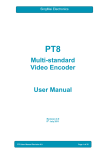
Figure 16 720p/60 Horizontal Timing
Chroma Modulator
The subcarrier frequency used to modulate the chroma is generated using a 32 bit ratio
counter clocked from the 148.5MHz clock. The subcarrier seed is programmable via registers
$10-$13.
ratio
Format
720p/60
720p/50
720p/30
720p/25
1080p/30
1080p/25
1080p/24
1080i/30
1080i/25
Fsc
θ sc subcarrier seed
phase change per line
pixels per line
148.5MHz 360
232
Pixels/line
1650
1980
3300
3960
2200
2640
2750
2200
2640
Line frequency
45.00kHz
37.50kHz
22.50kHz
18.75kHz
33.75kHz
28.125kHz
27.00kHz
33.75kHz
28.125kHz
FSC/FH ratio
549.5
659.5
1097.5
1317.5
731.5
879.5
915.5
731.5
879.5
Subcarrier
24.7275MHz
24.73125MHz
24.69375MHz
24.703125MHz
24.688125MHz
24.7359375MHz
24.7185MHz
24.688125MHz
24.7359375MHz
Seed value
2AA0BCAAH
2AA26454H
2A91D7A9H
2A95FAD4H
2A8F5C28H
2AA475EAH
2A9CC3DDH
2A8F5C28H
2AA475EAH
Table 4 aCVi Line and subcarrier frequencies.
The top 11 bits of this ratio counter (the phase word) are used by the demodulator to generate
the sine and cosine waveforms.
The subcarrier phase word is used to address a ROM containing sine and cosine values. A
sample of the sine waveform is added, after shaping, to the back porch of the video signal to
SC1 User Manual Revision 1.6
Page 27 of 52
SingMai Electronics
synchronise the chroma demodulator of the receiver. This colour burst is blanked during the
field pulse. The amplitude of the colour burst is programmable by registers $16 and $17.
The interpolated Cb and Cr chroma inputs are multiplied by two scaling coefficients, U =
0.493Cb, V=0.877Cr. These are multiplied in turn by the sine and cosine waveforms. The
resulting U.sin(2πFsc.t) and V.cos(2πFsc.t) data is added together to form the final chroma
signal which is scaled by the UV_scaling register value.
aCVi_Preemphasis
The colour burst, chroma and luma with composite sync are added to create the complete
aCVi output waveform.
A switchable sinx/x filter is applied to the composite signal to compensate for the high
frequency sampling losses in the output DAC. The response of the sinx/x filter is shown in
Figure 17.
In p h a s e F ilt e r F r e q u e n c y R e s p o n s e
0.25
0.00
Magnitude in dB
-0.25
-0.50
-0.75
-1.00
-1.25
-1.50
-1.75
-2.00
-2.25
0
10
20
30
40
50
60
70
80
F r e q u e n c y in M H z
Figure 17 Sinx/x Filter response.
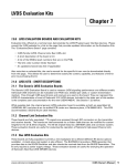
This waveform is then subjected to a variable degree of pre-emphasis with a maximum boost
of >40dB at >30MHz. The pre-emphasis filter is a 15 tap FIR.
The degree of pre-emphasis is dependent on the cable length and is designed to
approximately compensate for the loss of >500m of RG-59 or UTP cable (selectable via
Control register 3). The response of the pre-emphasis filter is shown below.
SC1 User Manual Revision 1.6
Page 28 of 52
SingMai Electronics
In p h a s e F ilt e r F r e q u e n c y R e s p o n s e
0
Magnitude in dB
-10
-20
-30
-40
-50
-60
0
10
20
30
40
F r e q u e n c y in M H z
Figure 18 Pre-emphasis filter response.
The resulting digital aCVI encoded output is fed to a digital to analogue converter (DAC) and
buffered to drive the cable.
Figure 19 aCVi output (Pre-emphasis = minimum).
SC1 User Manual Revision 1.6
Page 29 of 52
SingMai Electronics
Figure 20 aCVi waveform (pre-emphasis = maximum).
SC1 User Manual Revision 1.6
Page 30 of 52
SingMai Electronics
13. Data Transfers
The aCVi interface allows for the bi-directional transmission of control data between the
transmitter and receiver. The data is transferred during to two dedicated lines of the vertical
blanking interval, one for transmitter to receiver transmission, the other for receiver to
transmitter.
One byte of data is sent for each line, allowing a maximum of 60 bytes to be transferred each
second, (for a 60Hz frame rate).
The format of the data transfer is shown in Figure 21.
Figure 21 aCVi Data format
The format is the same regardless of the direction of transfer.
The first 8 bits are the framing byte which is a unique code signifying the beginning of data.
The receiving device must monitor the pre-defined vertical blanking line for this framing byte
which is a unique code.
The next four bits are a control word which defines the function of the following data byte. The
control words between transmitter and receiver and receiver and transmitter are different.
(See Tables 5 and 6).
SC1 User Manual Revision 1.6
Page 31 of 52
SingMai Electronics
C3
0
0
0
0
C2
0
0
0
0
C1
0
0
1
1
C0
0
1
0
1
Dec
0
1
2
3
0
0
0
0
1
1
1
1
1
1
1
1
1
1
1
1
0
0
0
0
1
1
1
1
0
0
1
1
0
0
1
1
0
0
1
1
0
1
0
1
0
1
0
1
0
1
0
1
4
5
6
7
8
9
10
11
12
13
14
15
Function
Pre-emphasis value for transmitter (auto cable equalization)
Select video Pattern:
$00 – Video
$01 – 75% colour bars
$02 – 30MHz multi-burst
$03 – 2T/30T pulse bar
Interface test
Table 5 Data transfer instructions: Receiver > Transmitter
C3
0
0
0
0
0
0
0
0
1
1
1
1
1
1
1
1
C2
0
0
0
0
1
1
1
1
0
0
0
0
1
1
1
1
C1
0
0
1
1
0
0
1
1
0
0
1
1
0
0
1
1
C0
0
1
0
1
0
1
0
1
0
1
0
1
0
1
0
1
Dec
0
1
2
3
4
5
6
7
8
9
10
11
12
13
14
15
Function
Measured Frame rate.
Interface test
Table 6 aCVi Control words Transmitter > Receiver
The next three bits must be a 010 sequence (to ensure the uniqueness of the framing byte).
The next 9 bits are the data for that control function. This is an 8-bit byte with any value
between 0 and 255. The data byte is separated into ‘nibbles’ each of 4 bits, separated by a
‘0’, again to ensure the uniqueness of the framing byte.
The last two bits are parity bits, one for the control word and one for the data word. The parity
bits are both even parity.
The total length of the data sequence is 27 bits. Each symbol (bit) is 32 x 1/74.25MHz long =
430ns. The low bit rate ensures that the data is received over long cable lengths even if the
pre-emphasis is incorrectly set, (the symbol length equates to a 2.23MHz data rate, which is
attenuated <2dB/100m of cable).
The total data sequence length is just under 12µs and it should be positioned centrally in the
active video period, although the exact position is not important.
The pre-defined video lines used for the transfer of data are the same for all standards. Data
is transmitted between transmitter to receiver on Line 7 and between receiver and transmitter
on line 8.
SC1 User Manual Revision 1.6
Page 32 of 52
SingMai Electronics
The process to send data is the same for transmitter and receiver. First the control word must
be written to the register $48. Next the data word is written to register $49. Once this is written
the two words are signaled for transfer on the next video frame. A status bit, write busy, is set
during this time. Further data transfers should not be initiated until this bit is reset.
Data Transfer Analogue Interface
The data interface between transmitter and receiver uses the same hardware as the video
interface with a small additional overhead required in the encoder IP cores.
The 27 bit word is loaded into a shift register at the beginning of the appropriate vertical
blanking line for insertion and then shifted out at the bit clock rate. The serial data stream is
shaped in a raised cosine filter to help avoid ringing and overshoot on the pulses.
For the receiver to transmitter direction a small additional overhead is required to receive the
data. The additional circuit for receiving data at the transmitter is shown in Chapter 20 (for
coaxial cable) and Chapter 21 (for UTP cable).
During the vertical interval the transmitter output amplifier outputs only synchronizing signals
and blanking level; the data from the receiver is overlaid on this blanking level. The received
data is AC coupled into a differential amplifier, (for CAT5 twisted pair cable).
The resulting output is then DC restored using a diode clamp. The DC restored video is
buffered by an op-amp configured as a comparator. The slice level of the comparator is set to
approximately 30% of the expected amplitude of the data pulses, to allow for up to 6dB of
attenuation in the input signal. The data is low bandwidth so the cable attenuation should
never exceed this.
The sliced output is then buffered and level converted to 3.3V for the FPGA input using a
Schmitt trigger.
SC1 User Manual Revision 1.6
Page 33 of 52
SingMai Electronics
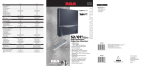
14. Video test signal insertion
To assist with the automatic cable length compensation a video test signal is inserted into line
9 of the vertical blanking interval. The signal consists of a black, grey and white reference
signal followed by a multi-burst at 5, 10, 15, 20, 25 and 30MHz frequencies. The waveform of
the test signal is shown in Figure 22.
Figure 22 Multi-burst video test insertion signal.
SC1 User Manual Revision 1.6
Page 34 of 52
SingMai Electronics
15. UART Data Transfer
It is possible to transmit continuous data from the receiver to the transmitter at data rates up
to 9600 baud.
SC1 User Manual Revision 1.6
Page 35 of 52
SingMai Electronics
16. FPGA Dimensions
Figure 23 FPGA Dimensions
SC1 User Manual Revision 1.6
Page 36 of 52
SingMai Electronics
17. FPGA PCB Design Guidelines
The FPGA is a 164 pin MBGA package with a 0.5mm ball pitch. However care has been
taken to ensure the device may be routed on a 4 layer PCB.
Figure 24 FPGA BGA Ball Dimensions
For the MBGA package dimension A and B in Figure 27 are 0.3mm and Altera recommends a
pad size of 0.26mm (10.24mils). To facilitate routing the track and gap dimensions below
should be followed:
Line width/space – 3mils.
Hole drill size – 6mils.
Via land size – 11mils.
Via land to line space – 3mils.
All of the unused pins of the FPGA are set to be inputs and therefore may be used for
through-routing. Figure 28 shows a suggested exit routing for the VCCIO, VCCINT and GND
connections. The stacking of the 4 layer PCB is shown below:
Layer 1: (Top) Signal routing.
Layer 2: Ground plane.
Layer 3: Split power plane. (VCCIO and 5V analogue)
Layer 4: (Bottom) Signal routing and VCCINT power plane in vicinity of FPGA.
SC1 User Manual Revision 1.6
Page 37 of 52
SingMai Electronics
Figure 25 FPGA Power and Ground routing.
SC1 User Manual Revision 1.6
Page 38 of 52
SingMai Electronics
18. Security IC Dimensions
Figure 26 Security IC Dimensions
SC1 User Manual Revision 1.6
Page 39 of 52
SingMai Electronics
19. FLASH IC Dimensions
Figure 27 FLASH IC Dimensions
SC1 User Manual Revision 1.6
Page 40 of 52
SingMai Electronics
20. SC1-EVAL Evaluation board
Figure 28 SC1 Evaluation board schematics - Sheet 1
SC1 User Manual Revision 1.6
Page 41 of 52
SingMai Electronics
Figure 29 SC1 Evaluation board schematics - Sheet 2
SC1 User Manual Revision 1.6
Page 42 of 52
SingMai Electronics
Figure 30 SC1 Evaluation board schematics - Sheet 3.
SC1 User Manual Revision 1.6
Page 43 of 52
SingMai Electronics
Figure 31 SC1 Evaluation board schematics - Sheet 4.
SC1 User Manual Revision 1.6
Page 44 of 52
SingMai Electronics
Figure 32 SC1 Evaluation board schematics - Sheet 5
SC1 User Manual Revision 1.6
Page 45 of 52
SingMai Electronics
Figure 33 SC1 Evaluation board schematics - Sheet 6.
SC1 User Manual Revision 1.6
Page 46 of 52
SingMai Electronics
21. UTP Schematics
Figure 34 SC1 Evaluation board schematics - UTP Output stage.
SC1 User Manual Revision 1.6
Page 47 of 52
SingMai Electronics
Figure 35 SC1 Evaluation board schematics - UTP Data slicer.
SC1 User Manual Revision 1.6
Page 48 of 52
SingMai Electronics
22. SC1 Parts Cost
The prices of the key components in the SC1 aCVi transmitter are shown below (coaxial
output). The prices have been negotiated with the suppliers shown based on the total aCVi Tx
quantity across all customers. SingMai will introduce you to those suppliers’ local
representatives in your country and you purchase directly from them at those prices.
Reference
U2
U5
U6
U7
U12
U9
Part No.
EP4CE15M8I7NGA
MX25L4006E
ALPU-MP
AD9705
AD8061
AD8648
Manufacturer
Altera
Macronix
Neowine
Analog Devices
Analog Devices
Analog Devices
Supplier
Arrow
SingMai
SingMai
ExcelPoint
ExcelPoint
ExcelPoint
Cost each
$3.80.
$2.00 (inclusive of
aCVi Tx license).
$1.76
$0.43
$0.69
Total
$8.08
Table 7 SC1 Key components costing
Additional parts, such as for local power supplies, have not been included in this pricing as
those supply rails may already be available in your design. However prices have also been
negotiated for the regulators used on the evaluation board, and they are shown in table 9.
Reference
U2
U3
U4
U14
Part No.
ADP3338-3V3
ADP1715-1V2
ADP1715-2V5
ADP3338-3V0
Manufacturer
Analog Devices
Analog Devices
Analog Devices
Analog Devices
Supplier
ExcelPoint
ExcelPoint
ExcelPoint
ExcelPoint
Cost each
$0.87
$0.54
$0.54
$0.87
Table 8 Power supply components costing
SC1 User Manual Revision 1.6
Page 49 of 52
SingMai Electronics
23. aCVi Demonstration boards
Demonstration/evaluation boards are available for the SC1 transmitter and SC10 receiver.
The modules convert from HD-SDI to aCVi (Tx) and then from aCVi to HD-SDI (Rx) allowing
an easy evaluation of aCVi’s performance with common available components.
The SC1 transmitter module is shown in Figure 36. The board is powered by the supplied
+5VDC AC/DC converter. The converter accepts all AC supply voltages from 90-250VAC.
When the power is connected a blue LED, D1, will light, indicating that the FPGA has been
configured correctly and that the board is running.
Connect up an HD-SDI source (e.g. camera) to the BNC. If the source is valid another blue
LED, D3, will light.
Figure 36 aCVi SC1 transmitter evaluation board.
It is necessary to manually configure the HD-SDI video standard. This is done using the DIP
switches 4 and 5 as shown in Figure 37.
Figure 37 SC1 switch functions.
SC1 User Manual Revision 1.6
Page 50 of 52
SingMai Electronics
For example, as shown in the above figure, switches 4 and 5 are both ON and therefore the
standard selected is 720p/60Hz.
It is suggested that to begin the transmitter and receiver are connected through a short length
of cable to test the installation. In which case the pre-emphasis switches, DIP switches 1-3
should all be set to ON, as shown in Figure 37.
The SC10 aCVi receiver module is shown in Figure 38. The module accepts the aCVi input
from the cable and converts it back to HD-SDI. The board again requires a 5VDC power
source supplied through the provided AC-DC power adaptor. Once powered a blue LED, D2,
will light to show the FPGA has been configured and the board is running. Connect the aCVi
input to the output of your cable and the HD-SDI output to a monitor or waveform monitor.
Figure 38 aCVi SC10 receiver evaluation board.
The SC10 board must be manually configured to the same standard as the transmitter using
the DIP switches (see Figure 39).
Figure 39 SC10 switch functions.
The SC10 has a character overlay that can be switched on using DIP switch 1. The overlay is
shown in Figure 40.
SC1 User Manual Revision 1.6
Page 51 of 52
SingMai Electronics
Figure 40 SC10 status overlay
The character overlay shows the status of the SC10 receiver. The abbreviations are as
follows:
FR
NP
BL
VG
SA
BA
SP
DI
DW
is the detected video frame rate (frames/second).
is the negative peak video value of the incoming video (8 bit digital value).
is the measured black level of the incoming video (8 bit digital value).
is the video gain (programmable gain amplifier) value
(relative value between 65 – 0dB – and 190 - +24dB).
is the sync amplitude value (BL – NP).
is the measured burst amplitude value.
is the voltage controlled gain status. The arrow indicates gain increasing,
decreasing or stable. The value is SA – VGA setpoint.
is the received data instruction word (15 indicates interface test).
is the received data word. This is a 0-255 incrementing count.
Once you have tested the basic setup of the SC1 and SC10 you can then insert longer cable
lengths. For example, if you insert 300m of cable the receiver automatic gain control will
compensate for the loss in sync amplitude. Once the AGC has settled you will see an image
but the colour will be washed out and high frequency luminance will be missing (the image will
be soft). Set the pre-emphasis of the transmitter to 300m and wait for the AGC to settle again.
Now we are compensating for the high frequency loss and you will the see the colours have
returned and the detail can again be seen in the image.
Note, when switching the pre-emphasis or switching between long cable lengths, the AGC
may take a few seconds to adjust to the set-point value.
SC1 User Manual Revision 1.6
Page 52 of 52