1
3.2.5 Video In put Unit
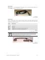
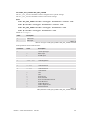
VISUPLUS can be equipped with video input units to insert video data. Each of these video input
units provides the facility for connecting one video source and to loop through the signal.
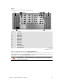
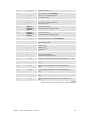
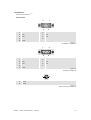
Connectors
1
VIDEO in
2
VIDEO out
3
SVHS in
4
SVHS out
Figure 3-13
video input unit
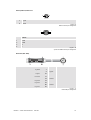
A composite video source can be connected to the VIDEO in [1] connector or an SVHS video
source can be connected to the SVHS in [3] connector. The video signal can be actively looped
through and with the VIDEO out [2] and SVHS out [4] connector respectively the signal can be connected to another device or VISUPLUS.
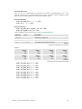
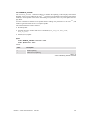
Order
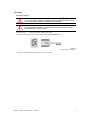
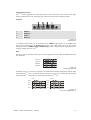
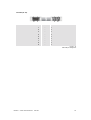
The input units are numbered from top to bottom beginning with 0. Video and RGB input units
may be mixed.
Video IPU 0
VIDEO in
VIDEO out
SVHS in
SVHS out
VISU+
VIDEO IPU
VIDEO in
VIDEO out
SVHS in
SVHS out
VISU+
VIDEO IPU
Video IPU 1
RGB IPU 2
RGB in
RGB out
VISU+
RGB IPU
RGB in
RGB out
VISU+
RGB IPU
RGB IPU 3
Figure 3-14
numbering of input units
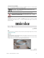
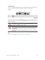
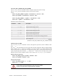
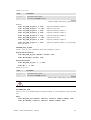
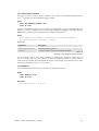
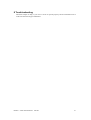
If multiple VISUPLUS are used, the input units are numbered continuously beginning with the input
units of the VISUPLUS that is connected directly to the EOS or control PC, continuing with the input
units of the VISUPLUS that is directly connected to the first VISUPLUS etc.
Plus
Visu
Plus
I
Visu
IPU 0
VIDEO in
VIDEO out
SVHS in
SVHS out
VISU+
VIDEO IPU
SVHS out
VISU+
VIDEO IPU
IPU 1
VIDEO in
VIDEO out
SVHS in
IPU 2
RGB in
RGB out
VISU+
RGB IPU
RGB out
VISU+
RGB IPU
IPU 3
RGB in
II
IPU 4
VIDEO in
VIDEO out
SVHS in
SVHS out
VISU+
VIDEO IPU
VIDEO in
VIDEO out
SVHS in
SVHS out
VISU+
VIDEO IPU
IPU 5
IPU 6
RGB in
RGB out
VISU+
RGB IPU
RGB in
RGB out
VISU+
RGB IPU
IPU 7
Figure 3-15
PLUS
input units in multiple VISU
R5976214
VisuPlus Video Insertion Unit
June 2003
3-11