1
7.
8.
9.
10.
11.
12.
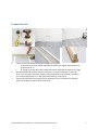
other forming a flat surface marking the location where each of the Trainer panels will
be mounted.
If mounting the panels on an uneven floor, use shims to ensure the plywood is
absolutely level.
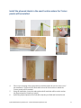
Anchor the plywood sheets to the studs using the supplied hardware. (2 bolts per stud,
6 per plywood)
On a wood stud wall, use a 1/8” drill bit and drill all locations where the ¼” lag bolts will
be used 3” deep. (It is very important to pre-drill the wood studs to prevent the wood from
splitting).
On a metal stud wall, use the impact gun with the 3” self-drilling screws.
Use the 2” fender washers at all locations for the plywood.
Tighten all 6 bolts per plywood using the 7/16” deep well socket (for wood studs) or the
3/8” socket for the sheet metal studs.
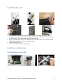
Open the Panel Boxes and remove panel marked P1 from the box
13.
14.
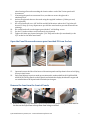
Open and remove the lids of the boxes of the station panels and lay them in front of wall lying
face up in their boxes.
Each panel belongs in pairs to make up a station and is numbered #P1A, #P1B, #P2A #P2B,
#P3A, #P3B. The top panels are the B panels and include the display board and 5 targets and
are installed above the A panels which include just 4 targets.
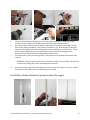
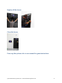
Remove the lens from the front of Panels
1. Remove the front polycarbonate covers from each of the panels and place them back in
the box on the Styrofoam to keep them from being scratched.
© 2015 Multisensory Fitness, Inc. • www.multisensoryfitness.com
9