1
11
Clara-W
A.2 INPUT DATA ORGANIZATION
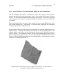
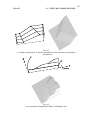
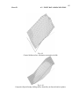
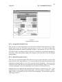
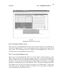
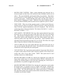
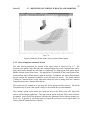
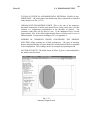
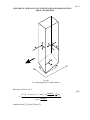
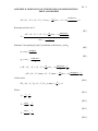
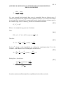
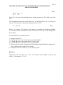
1) Orthogonal Interpolation: As illustrated in Fig. A.4a, this involves linear interpolation
between each pair of adjacent input points, first in the Y-direction and then in the Xdirection from one cross-section to another. This method is most suitable for uniform
geometries, or for general geometries or specified sliding surfaces. An example is
shown in Fig. A.4b.
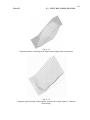
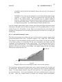
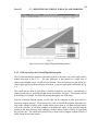
2) Oblique Interpolation: With this option, interpolation occurs first in the oblique
directions between each pair of input points located in adjacent cross-sections. The
rest of the mesh is filled by interpolating in the Y-direction (Fig. A.5a). Each input
cross-section must have the same number of points, otherwise an incomplete mesh
would result. The method is especially suitable for surfaces containing inclined
planar segments, such as man-made embankments or cuttings (Fig. A.5b). General
(specified) sliding surfaces cannot be used with this option.
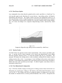
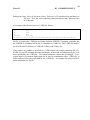
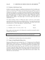
3) Axisymmetric Interpolation: Only one cross-section needs to be input with this
option. The column mesh will be generated by rotating this cross-section around a
vertical axis, placed at any selected pair of X and Y-coordinates. The rotation radius
is always measured in the y-direction, as if the input cross-section was located at the
same X-coordinate as the rotation centre (see Fig. A.6a). All the surfaces defined in
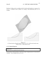
the cross-section are rotated, including piezometric surfaces. A concave slope will
result from a centre located downslope from the toe; a convex one if the centre is
located beyond the slope crest (Fig. A.6b). General sliding surfaces cannot be used.
Fig. A.4
a) Orthogonal interpolation. b) Example of a slope surface created by orthogonal
interpolation