1
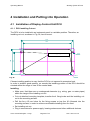
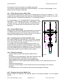
Operating Manual Bearing System RT 300 Place the DCU into the installing cut-out and fix it using the delivered M4 allen screws. 4.1.2 Connecting power supply The „Power Connector“ (see Fig. 2 ) is connecting DCU and power supply. Wiring pattern: PIN 5: GND (ground resp. negative pole). PIN 9: Voltage supply (+12 ... 24V) - The power supply has to be eqipped with a fuse of 1A, inert. - If the bearing system is to be operated floating, a DC/DC converter has to be adapted between Battery and DCU. The GND-connection is connected galvanically to the housing! 1 2 3 4 5 GND 6 7 8 9 Fig. 97 +12 .. 24V The content of delivery contains a prepared power supply cable. The red cable with integrated fuse holder is to be connected to the positive pole of the voltage supply (+12V ... 24V). The black cable is to be connected to the negative pole of the voltage supply Caution: We strongly point out, that a confusion of poles will damage the device. Never connect the black cable (PIN 5) to positive voltage. PIN 5 is connected to the ground of the housing and causes a short circuit, damaging the device! 4.1.3 Connecting the DCU to Ground The ground connector (Fig. 2 ) of the bearing system has to be connected to the ground of the vehicle. For stationary installations the ground connector has to be connected to earth potential. Use cables of sufficient cross-sectional area. Caution: The antenna´s ground is connected to the DCU. Electrostatic charge may cause very high voltages. Therefore, it is very important earthing the DCU before connecting the antenna. 4.1.4 Connecting Antenna Connect antenna cable (see 4.3) to socket “Antenna Connector“. 4.2 Determination of Antenna Position The quality of the bearing results is depending largely on the antenna´s position. So, an antenna position has to be found, where the transmitter´s wavefield can reach the bearing antenna as undisturbed as possible. The bearing antenna is analysing the incoming wavefield and the microprocessor of the bearing system is determining the direction of incidence of the signal. Reflections of the incoming signal may interfere with the wavefield. The bearing system will determine a direction of incidence as an average of the incoming and the reflected signal. As a result, Issue: 2013/03/04 [Rev 1.03.a] Page 64 of 72 12-9-1-0013-3-1-61