1
AR-B1631ET User’s Guide
ACROSSER®
AR-B1631ET (Extended Temperature)
powered by AMD Geode LX800, EPIC SBC with
CRT, LCD, LAN, USB2.0, PCI/104
User’s Guide
Edition: 1.0
1/30
AR-B1631ET User’s Guide
Contents
1 INTRODUCTION ............................................. 4
2 SYSTEM SETUP ............................................... 7
2.1 AR-B1631ET OVERVIEW........................................................... 7
2.2 SYSTEM SETTINGS................................................................... 8
2.2.1
2.2.2
2.2.3
2.2.4
2.2.5
2.2.6
2.2.7
2.2.8
2.2.9
2.2.10
2.2.11
2.2.12
2.2.13
2.2.14
2.2.15
2.2.16
2.2.17
2.2.18
2.2.19
2.2.20
2.2.21
2.2.22
2.2.22
JP5 (SERIRQ) ............................................................................. 8
JP1 (POWER ON) ...................................................................... 8
DIO1 (GPIO)............................................................................. 9
AUDIO1 (AUDIO) ...................................................................... 9
COM2, COM3, COM4 (RS232).................................................. 9
J2 (CHASSIS CONTROL)............................................................. 9
IR1......................................................................................... 10
J3 (CLEAR CMOS) ................................................................... 10
CN10 (LCD SETTING) .............................................................. 10
CDIN1 (CDIN) ........................................................................ 10
CN9 (POWER) ........................................................................ 10
CN8 (STAND BY POWER) ........................................................ 10
J5 (LCD BACKLIGHT) ................................................................ 11
JP4 (LCD LVDS) ........................................................................ 11
LPT1 (PARALLEL PORT) .............................................................. 11
BUZZER EXTERNAL .................................................................. 12
J4 (PC104+) ........................................................................... 12
JP6 (IDE Cable Select, NOTE 2) ................................................. 13
USBA_1 & USBA_2 (NOTE 2) ................................................... 13
USB1 & USB2 (NOTE 2) ........................................................... 13
JRS1....................................................................................... 13
CN4 (RS422 & RS485)............................................................. 14
CF1 (NOTE 1) ......................................................................... 14
3 LCD FLAT PANEL DISPLAY ..............................15
4 BIOS CONSOLE .............................................16
4.1
4.2
4.3
4.4
BIOS SETUP OVERVIEW ......................................................... 16
ADVANCED .......................................................................... 17
POWER ................................................................................ 18
PnP/PCI ................................................................................ 19
2/30
AR-B1631ET User’s Guide
4.5 PERIPHERALS ......................................................................... 19
4.6 BOOT................................................................................... 21
4.7 BIOS EXIT ............................................................................. 22
5 I/O ADDRESS, IRQ AND MEMORY MAPPING .23
5.1 I/O ADDRESS MAPPING ........................................................ 23
5.2 IRQ MAPPING....................................................................... 24
5.3 MEMORY MAPPING .............................................................. 24
6 GPIO SAMPLE CODE..................................... 25
3/30
AR-B1631ET User’s Guide
1
INTRODUCTION
Welcome to the AR-B1631ET Single Board Computer, the AR-B1631ET low power AMD Geode
LX800 processor board with the advanced chipset CS5536 (CS5535). The board is designed for
extreme environments, it can be operated from -40°C to +75°C which can make a lot of outdoor
applications available, such as Traffic Control, Vehicle Computer, Remote Workstation, Outdoor
Data Acquisition, Aviation or Military industries.
ACROSSER’s Extended Temperature Products contain onboard components that have been chosen
to withstand extreme operating temperatures. This platform has been fully loaded and passed robust
thermal cycling tests. It is a reliable, long life time and cost effective Extended Temperature solution
for your application.
In addition, the AR-B1631ET provides on chip VGA. The VGA, which provides up to
1920x1440x32bpp at 85Hz and 1600x1200x32bpp at 100HZ resolutions. The VGA memory is
shared with the main memory (2M, 4M, or 8M). AR-B1631ET also has 18-bit LVDS function in the
system, with a resolution up to 1600x1200x32bpp at 60Hz.
The AR-B1631ET is loaded with special on-board features that rival full-size systems. It has one
network controller on board, uses Realtek RTL8100BL LAN controller, a fully integrated
10/100BASE-TX solution with high performance networking functions. Supports Compact Flash™
Type II interface. Plus optional support for AC97 sound with CD-input. The AR-B1631ET also
includes one 200-pin SO-DIMM DDR sockets for up to 1GB total on-board memory. The
AR-B1631ET has four on-board serial ports; COM1 with RS232C, COM2, COM3 and COM4 with
RS232C, 4 USB ports, and tough industrial grade construction. All these features make the
AR-B1631ET a very "system integrator friendly" solution, perfect for handling applications in the
harshest unmanned environments.
4/30
AR-B1631ET User’s Guide
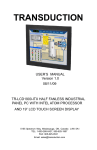
CRT
MEMORY BUS
LX Processor
TFT
lvds
(24Bit)
SODIMM200 DDR
CRT OUT
TO ETX
CON
PCI BUS(33MHz or 66MHz)
IDE AND
CF CARD
10/100M
Ethernet
PRIMARY IDE
ATA-66
South Bridge
(CS5535/CS5536)
USB2.0
AC97
CODEC
USB x 2
PCI(33/66 MHz)
14.318 MHz
Crystal
Clock
Synthesizer
(MK1491-09F)
66 MHz
48 MHz
LPC BUS
REFCLK
COM1
AND
COM2
W83627
Flash
BIOS
(SST FWH)
F81216D
COM3
AND
COM4
KB/MS
AR-B1631ET System Block Diagram
SPECIFICATIONS
CPU: AMD Geode LX800
Chipset: CS5536 or CS5535
RAM memory: Supports DDR400, on-board 200-pin SO-DIMM socket up to 1GB DDRAM
memory module
Display Interface: CRT – D-SUB 15-pin female connector
LVDS – for 18 bit TFT LCD Panel.
Touch Screen Header: shared with COM
Ultra ATA/33/66/100 IDE Interface:
Floppy disk drive interface: 2.88 MB, 1.44MB, 1.2MB, 720KB, or 360KB floppy disk
drive.
Compact Flash: Type II socket
Series ports: On-board one D-SUB 9-pin male connector for COM1 with RS-232C.
On-board one 2x5x2.00mm pin-header connector for COM2, COM3 and COM4 with
RS-232C.
Parallel Port: On-board one supports SPP/EPP/ECP modes
USB port: Four USB 2.0
Audio: onboard AC’97 Codec, Supports IN/OUT, and Left/Right speaker out, MIC IN,
CD IN.
Ethernet: On-board one RTL8100C, supports 10/100Mbps Base-T with RJ-45 connector
built-in LED
K/B & Mouse: On-board PS/2 Keyboard and Mouse connector
5/30
AR-B1631ET User’s Guide
Power Req.: +5V 2A and +12V 1A maximum
PC Board: 6 layers, EMI considered
GPIO: 8pin (4 output and 4 input) TTL compatible
PCB Dimensions: 6.5” x 4.5”, EPIC platform
Operating Temperature: -40°C ~ 75°C
Operating Humidity: 5~60% @75°C (non-condensing)
6/30
AR-B1631ET User’s Guide
2
SYSTEM SETUP
This chapter describes how to install the AR-B1631ET. At first, the layout of the AR-B1631ET is shown,
and the unpacking information is described.
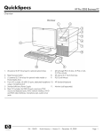
2.1 AR-B1631ET OVERVIEW
PC104+
LX800
CS5536
W83627HG
BIOS
IDE
RTL8100C
TOP VIEW
DDR
SODIMM
BOTTOM VIEW
7/30
AR-B1631ET User’s Guide
CN8 JP5
LPT1
J2
DIO1
AUDIO1
CDIN1
COM2
JP1
JRS1
JP6
CN10
COM4
JP4
CN4
COM3
CN9
J5
IR1
J3
USB_A2
USB_A1
2.2 SYSTEM SETTINGS
Jumper pins allow you to set specific system parameters. Set them by changing the pin location of
the jumper blocks. (A jumper block is a small plastic-encased conductor that slips over the pins.) To
change a jumper setting, remove the jumper from its current location with your fingers or small
needle-nosed pliers. Place the jumper over the two pins designated for the desired setting. Press the
jumper evenly onto the pins. Be careful not to bend the pins.
We will show the locations of the AR-B1631ET jumper pins, and the factory-default settings.
CAUTION: Do not touch any electronic components unless you are safely grounded. Wear a
grounded wrist strap or touch an exposed metal part of the system unit chassis. The static discharges
from your fingers can permanently damage electronic components.
2.2.1
JP5 (SERIRQ)
CLOSE
2.2.2
SERIRQ
JP1 (POWER ON)
POWER BUTTON
PIN HEADER
8/30
AR-B1631ET User’s Guide
2.2.3
DIO1 (GPIO)
1
2
9
10
2.2.4
GND
XOUT0
XOUT2
XIN0
XIN2
2
4
6
8
10
+5V
XOUT1
XOUT3
XIN1
XIN3
AUDIO1 (AUDIO)
1
2
9
2.2.5
10
1
3
5
7
9
LINE OUT R
GND
LINE IN R
MIC IN
GND
2
4
6
8
10
LINE OUT L
GND
LINE IN L
GND
GND
COM2, COM3, COM4 (RS232)
1
2
9
2.2.6
1
3
5
7
9
10
1
3
5
7
9
DCD
RX
TX
DTR
GND
2
4
6
8
10
DSR
RTS
CTS
RI
NC
J2 (CHASSIS CONTROL)
J2
POWER +
LED
-
AT
ATX
+
HD LED
-
RESET
9/30
AR-B1631ET User’s Guide
2.2.7
IR1
1
2
3
4
5
1
5
2.2.8
5V
NC
IRRX
GND
IRTX
J3 (CLEAR CMOS)
1
1-2
2-3
3
2.2.9
NORMAL
CLEAR
CMOS
CN10 (LCD SETTING)
1
2
5
1-3
3-5
2-4
4-6
6
-SHFCLK
SHFCLK
3.3V LCD
5V LCD
2.2.10 CDIN1 (CDIN)
1
1
2
3
4
4
CD_L
GND
GND
CD_R
2.2.11 CN9 (POWER)
1
2
2
+12V
GND
1
2.2.12 CN8 (STAND BY POWER)
3
1
1
2
3
+5V STANDBY
PSON#
GND
10/30
AR-B1631ET User’s Guide
2.2.13 J5 (LCD BACKLIGHT)
1
2
3
4
5
6
1
5
+12V
+12V
GND
BLT
GND
NC
2.2.14 JP4 (LCD LVDS)
2
1
30
2
4
6
8
10
12
14
16
18
20
22
24
26
28
30
29
GND
NC
NC
GND
NC
NC
NC
LVDS_TXC+
GND
LVDS_TX2LVDS_TX1+
NC
LVDS_TX0LVDS_TX3POWER
1
3
5
7
9
11
13
15
17
19
21
23
25
27
29
POWER
NC
GND
NC
NC
NC
NC
GND
LVDS_TXCLVDS_TX2+
NC
LVDS_TX1LVDS_TX0+
LVDS_TX3+
POWER
2.2.15 LPT1 (PARALLEL PORT)
1
14
1
2
3
4
5
6
7
8
9
10
11
12
13
13
STBD0
D1
D2
D3
D4
D5
D6
D7
ACKBUSY
PE
SELECT
14
15
16
17
18
19
20
21
22
23
24
25
26
AFDERRORINITSLINGND
GND
GND
GND
GND
GND
GND
GND
NC
26
11/30
AR-B1631ET User’s Guide
2.2.16 BUZZER EXTERNAL
2.2.17 J4 (PC104+)
A1 B1 C1 D1
1
2
3
4
5
6
7
8
9
10
11
12
13
14
15
16
17
18
19
20
21
22
23
24
25
26
27
28
29
30
A
NC
NC
AD5
C/BE0#
GND
AD11
AD14
+3.3V
SERR#
GND
STOP#
+3.3V
FRAME#
GND
AD18
AD21
+3.3V
IDSEL0
AD24
GND
AD29
+5V
REQ0#
GND
GNT1#
+5V
CLK
GND
+12V
NC
B
SERIRQ
AD2
GND
AD7
AD9
NC
AD13
C/BE1#
GND
PERR#
+3.3V
TRDY#
GND
AD16
+3.3V
AD20
AD23
GND
C/BE3#
AD26
+5V
AD30
GND
REQ2#
NC
CLK
+5V
INTD#
INTA#
NC
C
+5V
AD1
AD4
GND
AD8
AD10
GND
AD15
PULL UP
+3.3V
LOCK#
GND
IRDY#
+3.3V
AD17
GND
AD22
IDSEL1
NC
AD25
AD28
GND
REQ1#
+5V
GNT2#
GND
NC
+5V
INTB#
NC
D
AD0
+5V
AD3
AD6
GND
NC
AD12
+3.3V
PAR
PULL UP
GND
DEVSEL#
+3.3V
C/BE2#
GND
AD19
+3.3V
AD22
AD23
GND
AD27
AD31
NC
GNT0#
GND
CLK
GND
PCIRST#
INTC#
NC
A30 B30 C30 D30
12/30
AR-B1631ET User’s Guide
2.2.18 JP6 (IDE Cable Select, NOTE 2)
Open
Close
ATA33
ATA66 above
2.2.19 USBA_1 & USBA_2 (NOTE 2)
1
2
9
10
1
2
3
4
5
6
7
8
9
10
5V
5V
USB1USB2USB1+
USB2+
GND
GND
GND
GND
2.2.20 USB1 & USB2 (NOTE 2)
1
2
3
4
5
6
7
8
5V
USBUSB+
GND
5V
USBUSB+
GND
2.2.21 JRS1
1
2
5
6
1-2
3-4
5-6
RS422
RS485
RS232
13/30
AR-B1631ET User’s Guide
2.2.22 CN4 (RS422 & RS485)
1
4
1
2
3
4
RS422TX+/RS485TRX+
RS422TX-/RS485TRXRS422RX+
RS422RX-
2.2.22 CF1 (NOTE 1)
NOTE 1:
For using both Hard Disk and Compact Flash, you have to use the ATA33 IDE cable.
IF you want to use the ATA66/100 mode with the Hard Disk, you must put the
jumper on JP6 and use the special IDE cable.
The cable is like below:
IDE HOST
Usually the ATA66/100 cable
at Pin 34 at host side is
defined as CABLE ID and
connected to ground.
Usually the ATA66/100 cable and Pin 34 are disconnected
between host and device side.
IDE DEVICE
The special cable must be connected to this PDIAG signal from
host side to device side.
With special cables, Pin 34 is
defined as PDIAG and
cannot be connected to
PDIAG
PIN34
NOTE 2:
USB connectors (USB1 & USB2) and USB Pin headers cannot be used together. If
you want to use USB connectors, you must take the USB cable on Pin Header.
14/30
AR-B1631ET User’s Guide
3
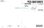
LCD FLAT PANEL DISPLAY
This chapter describes the configuration and installation procedures for LCD displays.
LVDS1
LCD
Panel
AR-B1631ET
Backlight
connect to J5
Inverter
Backlight
Power
LCD Panel Block Diagram
Please visit our web site or contact our technical support department for supports of LCD connecting.
15/30
AR-B1631ET User’s Guide
4
BIOS CONSOLE
This chapter describes the AR-B1631ET BIOS menu displays and explains how to perform common
tasks needed to get up and running, and presents detailed explanations of the elements found in
each of the BIOS menus. The following topics are covered:
BIOS Setup Overview
Advanced CMOS Setup
Peripheral Setup
Boot
BIOS Exit
4.1 BIOS SETUP OVERVIEW
The BIOS is a program used to initialize and set up the I/O system of the computer, which includes
the ISA bus and connected devices such as the video display, floppy drive, and the keyboard.
The BIOS provides a menu-based interface to the console subsystem. The console subsystem
contains special software, called firmware that interacts directly with the hardware components and
facilitates interaction between the system hardware and the operating system.
The BIOS default values ensure that the system will function at its normal capability. In the worst
situation the user may have corrupted the original settings set by the manufacturer.
After the computer is turned on, the BIOS will perform diagnostics on the system and display the size
of the memory that is being tested. Press the [Del] key to enter the BIOS Setup program, and the
main menu will show on the screen.
The BIOS Setup main menu includes some options. Use the [Up/Down] arrow key to highlight the
option that you wish to modify, and then press the [Enter] key to select the option and to configure
the functions.
Setup Main Menu
16/30
AR-B1631ET User’s Guide
The <Main> option allows you to view some basic system hardware configuration and to set the
system clock as well as error handling. If the CPU board is already installed in a working system, you
do not need to select this option anymore.
Date & Time Setup
Highlight the <Date> field and then press the [Page Up] / [Page Down] or [+]/[-] keys to set the
current date. Follow the month, day and year format.
Highlight the <Time> field and then press the [Page Up] / [Page Down] or [+]/[-] keys to set the
current date. Follow the hour, minute and second format.
Hard Disk Setup
The BIOS supports 2 types of user settings. The BIOS supports <Pri Master> and <Pri Slave>, <Sec
Master> and <Sec Slave> so the user can install up to two hard disks.
4.2 ADVANCED
Standard CMOS Setup
Quick Power On Self Test
Allows the system to skip certain tests while booting. This will decrease the time needed to boot the
system.
Full Screen Logo Show [Disable]
This allows you to enable or disable the full screen logo display feature.
Configuration options: [Disabled] [Enabled]
INIT Display First [Onboard]
Initialize the onboard video display before initializing any other display device on the system.
Thus the onboard display becomes the primary display.
Configuration options: [Disabled] [Enabled]
17/30
AR-B1631ET User’s Guide
Video Memory Size [8M]
Configuration options: [None] [8M] [16M] [32M] [64M] [128M] [254M]
Output Display [CRT]
This allows you to choose the output of your system display.
Configuration options: [CRT] [Flat Panel] [Panel +CRT]
Flat Panel Type [Auto]
This allows you to choose the flat panel type
Configuration options: [Auto] [LVDS] [TFT]
Resolution [800x600]
This allows you to choose the display resolution.
Refresh Rate [60Hz]
This allows you to choose the display Refresh Rate.
CPU / MEM / PCI Frequency [Auto]
This allows you to set the memory frequency.
Configuration options:
100/133/166/200
4.3 POWER
Power Management [ACPI]
This allows you to enable or disable the ACPI function Configuration options: [Disabled] [ACPI]
18/30
AR-B1631ET User’s Guide
4.4 PnP/PCI
PnP/PCI
Reset Configuration Data [Disable]
Normally, you leave this field Disabled. Select Enabled to reset the Extended System Configuration
Data (ESCD) when you exit the Setup if you have installed a new add-on and the system
reconfiguration has caused such a serious conflict that the operating system cannot boot.
Resources Controlled By [Auto (ESCD)]
This field sets control over the IRQ resources by the automatic (ESCD) system or manual assignment
of IRQ channels. The default enables the automatic (ESCD) control. Configuration options: [Auto
(ESCD)] [Manual].
4.5 PERIPHERALS
Peripherals
19/30
AR-B1631ET User’s Guide
Onboard Serial Port 1 [3F8/IRQ4]
Choose the serial port 1 I/O address. Do not set port 1, 2, 3 and 4 to the same address except for
Disabled or Auto.
Onboard Serial Port 2 [2F8/IRQ3]
Choose the serial port 2 I/O address. Do not set port 1, 2, 3 and 4 to the same address except for
Disabled or Auto.
Onboard Serial Port 3 [3E8/IRQ11]
Choose the serial port 3 I/O address. Do not set port 1, 2, 3 and 4 to the same address except for
Disabled or Auto.
Onboard Serial Port 4 [2E8/IRQ10]
Choose the serial port 4 I/O address. Do not set port 1, 2, 3 and 4 to the same address except for
Disabled or Auto.
Onboard Parallel Port [378H/IRQ7]
This field allows you to set the address of the onboard parallel port connector. If you disable this
field, the Parallel Port Mode and ECP DMA Select configurations are not available. Configuration
options: [Disabled] [378H/IRQ7] [278H/IRQ5]
Parallel Port Mode [SPP]
This field allows you to set the operation mode of the parallel port. [Normal] allows normal-speed
operation but in one direction only; [EPP] allows bidirectional parallel port operation; [ECP] allows
the parallel port to operate in bidirectional DMA mode; [ECP+EPP] allows normal speed operation
in a two-way mode. Configuration options: [Normal] [EPP] [ECP] [ECP+EPP]
Parallel port EPP Type [EPP1.7]
The mode depends on your external device that connects to this port.
ECP Mode use DMA [3]
This field allows you to configure the parallel port DMA channel for the selected ECP mode. This
selection is available only if you select [ECP] or [ECP+EPP] in Parallel Port Mode above.
Configuration options: [1] [3]
Onboard Audio [Enabled]
Should be enabled for active AC97
USB1 Controller [Enabled]
This should be enabled if your system has a USB Controller installed on the system board and you
want to use it. Even when so equipped, if you add a higher performance controller, you will need
to disable this feature.
USB2 Controller [Enabled]
This should be enabled if your system has a USB Controller installed on the system board and you
want to use it. Even when so equipped, if you add a higher performance controller, you will need
to disable this feature.
20/30
AR-B1631ET User’s Guide
OnChip IDE Device
With this option you can enable or disable your IDE channel and set the PIO mode or UDMA
mode.
4.6 BOOT
BOOT
First/Second/Third Boot Device
HDD-0
SCSI
CDROM
HDD-1
USB-FDD
USB-ZIP
USB-CDROM
USB-HDD
LAN
Disabled
Boot Other Device [Enabled]
Configuration options: [Enabled] [Disabled].
LAN Boot Select [Disabled]
This allows you to enable or disable the LAN Boot function.
21/30
AR-B1631ET User’s Guide
4.7 BIOS EXIT
Exit
When you have made all of your selections from the various menus in the Setup program, save
your changes and exit Setup. Select Exit from the menu bar to display the following menu.
Save & Exit Setup
Typing “Y” will quit the Setup Utility and save the user setup value to RTC CMOS. Type “N” will
return to Setup Utility.
Load Optimized Defaults
Selecting this field loads the factory defaults for BIOS and Chipset Features that the System
automatically detects.
Exit Without Saving
Typing “Y” will quit the Setup Utility without saving to RTC CMOS.
Typing “N” will return to the Setup Utility.
Set Password
This allows you to set a password for the BIOS menu.
22/30
AR-B1631ET User’s Guide
5
I/O ADDRESS, IRQ AND MEMORY
MAPPING
5.1 I/O ADDRESS MAPPING
23/30
AR-B1631ET User’s Guide
5.2 IRQ MAPPING
5.3 MEMORY MAPPING
24/30
AR-B1631ET User’s Guide
6
GPIO SAMPLE CODE
/*[]=====================================================================[]*/
/*|| GPIO Test utility for W83627HF.
||*/
/*|| Date : 10/18/2005
||*/
/*|| Author : Willy
||*/
/*[]=====================================================================[]*/
/*[]=====================================================================[]*/
/*|| Include files
||*/
/*[]=====================================================================[]*/
#include <conio.h>
#include <stdio.h>
/*[]=====================================================================[]*/
/*|| Assember Types Define
||*/
/*[]=====================================================================[]*/
typedef unsigned char
BYTE;
typedef unsigned short int WORD;
typedef unsigned long int DWORD;
void Show_Title();
char YES_NO_Confirm();
void Enter_Config(BYTE IO_PORT_BASE);
void Exit_Config(BYTE IO_PORT_BASE);
void Init_SIO(BYTE IO_PORT_BASE);
int GPI_TEST(BYTE IO_PORT_BASE);
int GPO_TEST(BYTE IO_PORT_BASE);
/*[]=====================================================================[]*/
/*|| Function : GPI_TEST()
||*/
/*|| Input : BYTE IO_PORT_BASE
||*/
/*|| Change : ||*/
/*|| Return
: Pass return "0", Fail return "1".
||*/
/*|| Description: Test GPI Pins status.
||*/
/*[]=====================================================================[]*/
int GPI_TEST(BYTE IO_PORT_BASE)
{
BYTE Read_Byte,Temp_Word,Show_Byte;
// Set W83627HF GPIO10~17 to Input
outportb(IO_PORT_BASE,0xF0);
outportb(IO_PORT_BASE+1,0xFF);
printf(">>>>> GPI Test Start <<<<<");
25/30
AR-B1631ET User’s Guide
/////// Input High Test ///////////////////////////////////////////////////
printf("\nConnect GPI Pins to High ? [Y/N] ....... ");
if(YES_NO_Confirm() =='n')
{ printf("\n>>>>> GPI Test Error <<<<<\n"); return 1; }
// return fail
Show_Byte=0x00;
// Read W83627HF GPIO10~17 Status
outportb(IO_PORT_BASE,0xF1);
Read_Byte=inportb(IO_PORT_BASE+1);
if(Read_Byte&0x01)
//GPI10
Show_Byte=Show_Byte|0x01; else
if(Read_Byte&0x02)
//GPI11
Show_Byte=Show_Byte|0x02; else
if(Read_Byte&0x04)
//GPI12
Show_Byte=Show_Byte|0x04; else
if(Read_Byte&0x08)
//GPI13
Show_Byte=Show_Byte|0x08; else
if(Read_Byte&0x10)
//GPI14
Show_Byte=Show_Byte|0x10; else
if(Read_Byte&0x20)
//GPI15
Show_Byte=Show_Byte|0x20; else
if(Read_Byte&0x40)
//GPI16
Show_Byte=Show_Byte|0x40; else
if(Read_Byte&0x80)
//GPI17
Show_Byte=Show_Byte|0x80; else
Show_Byte=Show_Byte&0xFE;
Show_Byte=Show_Byte&0xFD;
Show_Byte=Show_Byte&0xFB;
Show_Byte=Show_Byte&0xF7;
Show_Byte=Show_Byte&0xEF;
Show_Byte=Show_Byte&0xDF;
Show_Byte=Show_Byte&0xBF;
Show_Byte=Show_Byte&0x7F;
if(Show_Byte==0xFF)
printf("\nGPI Pins input value ==> 0x%002X",Show_Byte);
else
{ printf("\nGPI Pins input value ==> 0x%002X (should be 0xFF)",Show_Byte);
printf("\n>>>>> GPI Test Error <<<<<\n"); return 1; } // return fail
/////// Input Low Test ////////////////////////////////////////////////////
printf("\nConnect GPI Pins to Low ? [Y/N] ........ ");
if(YES_NO_Confirm() =='n')
{ printf("\n>>>>> GPI Test Error <<<<<\n"); return 1; }
// return fail
Show_Byte=0x00;
// Read W83627HF GPIO10~17 Status
outportb(IO_PORT_BASE,0xF1);
Read_Byte=inportb(IO_PORT_BASE+1);
if(Read_Byte&0x01)
//GPI10
Show_Byte=Show_Byte|0x01; else Show_Byte=Show_Byte&0xFE;
if(Read_Byte&0x02)
//GPI11
Show_Byte=Show_Byte|0x02; else Show_Byte=Show_Byte&0xFD;
if(Read_Byte&0x04)
//GPI12
26/30
AR-B1631ET User’s Guide
Show_Byte=Show_Byte|0x04; else
if(Read_Byte&0x08)
//GPI13
Show_Byte=Show_Byte|0x08; else
if(Read_Byte&0x10)
//GPI14
Show_Byte=Show_Byte|0x10; else
if(Read_Byte&0x20)
//GPI15
Show_Byte=Show_Byte|0x20; else
if(Read_Byte&0x40)
//GPI16
Show_Byte=Show_Byte|0x40; else
if(Read_Byte&0x80)
//GPI17
Show_Byte=Show_Byte|0x80; else
Show_Byte=Show_Byte&0xFB;
Show_Byte=Show_Byte&0xF7;
Show_Byte=Show_Byte&0xEF;
Show_Byte=Show_Byte&0xDF;
Show_Byte=Show_Byte&0xBF;
Show_Byte=Show_Byte&0x7F;
if(Show_Byte==0x00)
printf("\nGPI Pins input value ==> 0x%002X",Show_Byte);
else
{ printf("\nGPI Pins input value ==> 0x%002X (should be 0x00)",Show_Byte);
printf("\n>>>>> GPI Test Error <<<<<\n"); return 1; } // return fail
printf("\n>>>>> GPI Test End
return 0;
// return pass
<<<<<\n");
}
/*[]=====================================================================[]*/
/*|| Function : GPO_TEST()
||*/
/*|| Input : BYTE IO_PORT_BASE
||*/
/*|| Change : ||*/
/*|| Return
: Pass return "0", Fail return "1".
||*/
/*|| Description: Test GPO Pins status.
||*/
/*[]=====================================================================[]*/
int GPO_TEST(BYTE IO_PORT_BASE)
{
// Set W83627HF GPIO10~17 to Output
outportb(IO_PORT_BASE,0xF0);
outportb(IO_PORT_BASE+1,0x00);
printf(">>>>> GPO Test Start <<<<<");
/////// Output High Test /////////////////////////////////////////////////
printf("\nSet GPO Pins to High ...............");
// Set W83627HF GPIO10~17 to High
outportb(IO_PORT_BASE,0xF1);
outportb(IO_PORT_BASE+1,0xFF);
printf("\nGPO Pins is High ? [Y/N] ........... ");
if(YES_NO_Confirm() =='n')
{ printf("\n>>>>> GPO Test Error <<<<<\n"); return 1; }
// return fail
/////// Output Low Test //////////////////////////////////////////////////
printf("\nSet GPO Pins to Low ................");
27/30
AR-B1631ET User’s Guide
// Set W83627HF GPIO10~17 to Low
outportb(IO_PORT_BASE,0xF1);
outportb(IO_PORT_BASE+1,0x00);
printf("\nGPO Pins is Low ? [Y/N] ............ ");
if(YES_NO_Confirm() =='n')
{ printf("\n>>>>> GPO Test Error <<<<<\n"); return 1; }
printf("\n>>>>> GPI Test End
return 0;
// return pass
// return fail
<<<<<\n");
}
/*[]=====================================================================[]*/
/*|| Main procedure
||*/
/*[]=====================================================================[]*/
int main(int argc, char *argv[])
{
BYTE
IO_PORT_BASE=0x2E; // DATA_PORT = IO_PORT_BASE + 1;
int result;
if ( argc != 2 )
{ Show_Title();
return 1; }
clrscr();
// Enter W83627HF Config
Enter_Config(IO_PORT_BASE);
Init_SIO(IO_PORT_BASE);
switch(argv[1][0])
{
case 'i':
case 'I':
//I Key
result=GPI_TEST(IO_PORT_BASE);
if(result==0)
printf("Test Result is Pass.");
else
printf("Test Result is Fail.");
break;
case 'o':
case 'O':
//O Key
result=GPO_TEST(IO_PORT_BASE);
if(result==0)
printf("Test Result is Pass.");
else
printf("Test Result is Fail.");
break;
} //switch end
// Exit W83627HF Config
Exit_Config(IO_PORT_BASE);
28/30
AR-B1631ET User’s Guide
return(0);
}
/*[]=====================================================================[]*/
/*|| Function : Show_Title()
||*/
/*|| Input : ||*/
/*|| Change : ||*/
/*|| Return
:||*/
/*|| Description: Show Title string.
||*/
/*[]=====================================================================[]*/
void Show_Title()
{
clrscr();
printf("GPIO Control test for W83627HF\n");
printf("1. GPIO.EXE I ==--> Test GPI.\n");
printf("2. GPIO.EXE O ==--> Test GPO.\n");
}
/*[]=====================================================================[]*/
/*|| Function : YES_NO_Confirm()
||*/
/*|| Input : ||*/
/*|| Change : ||*/
/*|| Return
: character 'y' or 'n'
||*/
/*|| Description: Confirm get 'Y' or 'N' key.
||*/
/*[]=====================================================================[]*/
char YES_NO_Confirm()
{
int X_Axis,Y_Axis;
char y_n;
X_Axis=wherex();
Y_Axis=wherey();
/* Get Cursor X Axis */
/* Get Cursor Y Axis */
while(1) {
y_n=getche();
if(y_n=='y' || y_n=='Y')
return('y');
else if(y_n=='n' || y_n=='N')
return('n');
else
gotoxy(X_Axis,Y_Axis);
}
}
/*[]=====================================================================[]*/
/*|| Function : Enter_Config()
||*/
/*|| Input : BYTE IO_PORT_BASE
||*/
/*|| Change : ||*/
/*|| Return
:||*/
/*|| Description: Enter chip configuration key.
||*/
/*[]=====================================================================[]*/
29/30
AR-B1631ET User’s Guide
void Enter_Config(BYTE IO_PORT_BASE)
{
outportb(IO_PORT_BASE,0x87);
outportb(IO_PORT_BASE,0x87);
}
/*[]=====================================================================[]*/
/*|| Function : Exit_Config()
||*/
/*|| Input : BYTE IO_PORT_BASE
||*/
/*|| Change : ||*/
/*|| Return
:||*/
/*|| Description: Exit chip configuration key.
||*/
/*[]=====================================================================[]*/
void Exit_Config(BYTE IO_PORT_BASE)
{
outportb(IO_PORT_BASE,0xAA);
}
/*[]=====================================================================[]*/
/*|| Function : Init_SIO()
||*/
/*|| Input : ||*/
/*|| Change : ||*/
/*|| Return
: character 'y' or 'n'
||*/
/*|| Description: Confirm get 'Y' or 'N' key.
||*/
/*[]=====================================================================[]*/
void Init_SIO(BYTE IO_PORT_BASE)
{
/* Set Multi-function Pins to GPIO */
outportb(IO_PORT_BASE,0x2A);
outportb(IO_PORT_BASE+1,(inportb(IO_PORT_BASE+1) | 0xFC));
// Select GPIO Port device
outportb(IO_PORT_BASE,0x07);
outportb(IO_PORT_BASE+1,0x07);
// Set GPIO Port Active
outportb(IO_PORT_BASE,0x30);
outportb(IO_PORT_BASE+1,0x01);
}
30/30