1
XG2130 E1/Datacom Tester
Performing Measurements
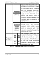
aligned to the middle of the data. This coincidence helps the
equipment clock in or out the data properly. It is very
important for user to configure the valid edge of sampling or
transmitting the data. But various equipments from different
vendors don’t treat the clock edge in the same way. The valid
edge of the clock signals is always uncertain to the user.
Therefore, when making the synchronous measurements with
the equipment under test, the user need to know the valid
edge of clocks of the equipment under test firstly or try to
adjust the valid edge of the clock when not sure about it .
If the instrument has no clock edge adjustment function, the
test may be failed to the equipments from different vendors.
The valid edge of transmit and receive clock signals is normally
configured as the rising edge. The rising edge configuration
may be effective for most digital equipments.
d). Handshaking Signal Testing
A typical datacom interface always has some control circuits
for handshaking before the connection is established, for
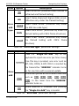
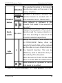
example “RTS/CTS” and “DTR/DSR”. The E1/Datacom tester
can monitor the status of these handshaking signals in real
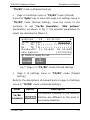
time. In “Settings” menu of a synchronous test, all the status
of input handshaking signals can be displayed with “ON” or
“OFF”, and all the output handshaking signals of the control
circuits can be set with ON or OFF.
“ON” status is defined as a “High” in logic and “OFF” is defined
as a “Low” in logic. Since the logic “High” and “Low” stand for
72-0027-03A
142