1
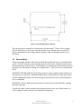
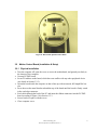
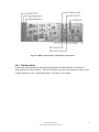
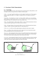
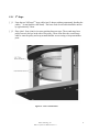
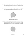
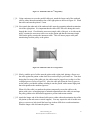
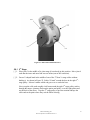
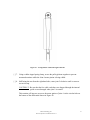
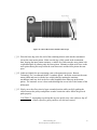
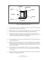
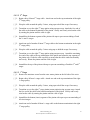
3 System Setup
This section describes the steps required to interconnect the components of the BarrettArm
system, power up the system, and perform some routine system checks. Do not proceed until
the workspace has been prepared according to Section 1.7. Unless explicitly noted, all Section
3 instructions referencing the optional BarrettWrist can be ignored if the user is setting up only
the 4-DOF BarrettArm.
3.1 Mechanical Connections
Upon receipt of a BarrettArm system, the floor mount (bottom-most plate in the arm-base)
must be securely bolted to the surface on which the arm rests. The BA4-300 uses four M8-1.25
or 3/8”-16 (depending on the user’s preparation of the mounting surface) socket cap screws for
this purpose.
The optional BarrettWrist is connected by aligning the metal shells of the integrated D-sub
connectors at its base with the mating connector’s shells on the end of the BarrettArm’s
“elbow” and threading the quick-connect ring onto the wrist base. No special wrenches,
fasteners, or tools are required. Note that this single operation also makes all electrical
connections to the BarrettWrist.
Figure 7 - BarrettArm Floor Mount
Barrett Technology, Inc.
BA4-310 System User Manual Version 1.1
16