1
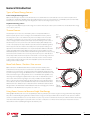
the speed the heat flows out of the same region. The response time is approximately proportional to the aperture, i.e. a 50mm aperture
disc is three times as slow as an 18mm aperture disc.
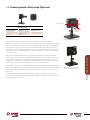
Thermal Surface Absorbing Heads
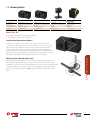
1.1 Sensors
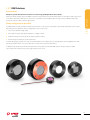
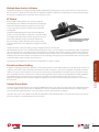
A surface absorber typically consists of an optically absorbing refractory material deposited on a heat conducting substrate of copper or
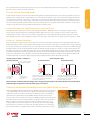
aluminum. When a long pulse of several hundred µs or a continuous laser beam falls on such a surface absorber, the light is absorbed in
a very thin layer of the surface – typically 0.1 – 1µm thickness (see illustration A). Although the light is absorbed in a thin layer and there
converted into heat, the pulse is long enough so that while energy is being deposited into the surface layer, heat is also flowing out into
the heat conducting substrate and therefore the surface does not heat up excessively. Ophir standard surface absorbers can stand up to
10 Joules/cm2 for 2ms pulses and up to 28kW/cm2 for low power continuous lasers.
Surface Absorbers for High Power Lasers and Long Pulses
The traditional surface absorbers have a much lower damage threshold at > 1000W, where they can damage at 2-3 kW/cm2. Ophir
has developed coatings that improve the damage threshold for high power lasers. These coatings are denser and have higher heat
conductivity than previous coatings. These LP and LP1 coatings also have a much higher damage threshold for long pulses reaching
power damage thresholds of up to 100kW/cm² and 250J/cm² for 10ms pulses. Surface absorbers are suitable for pulses longer than ~100µs.
Surface vs. Volume Absorbers
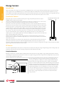
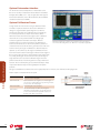
When measuring a laser with short pulses of tens of µs or less, the heat is deposited in a short time and cannot flow during the pulse (see
illustration B below). Therefore a surface absorber which absorbs the energy in a thin surface layer is not suitable. All the energy is deposited
in a thin layer and that layer is vaporized. In this case, volume absorbers are used. These have traditionally consisted of a neutral density glass
thermally bonded to a heat-conducting metallic substrate. The ND glass absorbs the light over a depth of 1-3 mm instead of fractions of a
micrometer. Consequently, even with short pulses where there is no heat flow, the light and heat are deposited into a considerable depth
of material and therefore the power/energy meter with aa volume absorber is able to withstand much higher energy densities – up to 10
Joules/cm2 (see illustration C). These ND glasses form the basis of the Ophir P type absorbers. In addition to the P absorbers, Ophir has PF
and SV absorbers that can stand up to higher average powers and power densities as well as EX absorbers for the UV.
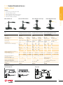
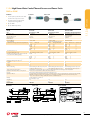
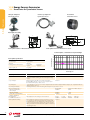
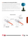
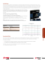
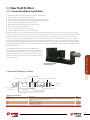
Long laser pulse (>100µs) or continuous (A) Surface absorber Heat conducting copper
Short laser pulse <10µs
(B) Surface absorber
(C) Volume absorber
Laser
pulse
Laser
pulse
or aluminum substrate
Laser
pulse
Depth of light
penetration
~0.1-1µm
Heat flows into
substrate during
laser pulse
Depth of light penetration ~0.1-1µm. Light
and heat concentrated same thin layer. Heat
does not have a chance to flow during the
short laser pulse duration.
Light is absorbed gradually over thick
partially transmitting layer. Heat is therefore
generated over large volume even during
short pulse with no heat flow.
Surface absorbers work best when measuring power or energy for long laser pulses (A). Volume absorbers can measure pulses
with much higher energies than surface absorbers (B), (C) can measure.
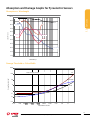
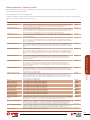
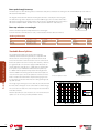
Calibration Method and Estimated Accuracy for Ophir High Power Sensors
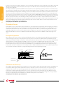
Ophir models 5000W, 10K-W and Comet 10K are calibrated using relatively low power lasers
~ 150 - 300W. Using such low power lasers to calibrate the instrument vs. the high power
at which the sensors are used raises the question of calibration accuracy. The following
explanation clearly demonstrates that the 5000W, 10K-W and Comet 10K are indeed
accurate to ±5% over their measurement range. The 5000W and 10K-W sensors work on the
thermopile principle, where the radial heat flow in the absorber disk causes a temperature
difference between the hot and cold junctions of the thermopile which in turn causes
a voltage difference across the thermopile. Since the instrument is a thermopile voltage
generating device, it must be linear at low values of output. Therefore, if it is shown to be
linear at powers which are a significant fraction of the maximum power, it will necessarily
19
For latest updates please visit our website: www.ophiropt.com/photonics
01.08.2013