1
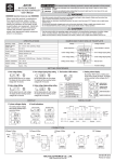
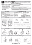
TIMING CHART(Output mode)
A : Signal ON delay 1
(Timer resets when power comes ON.)
B : Repeat cycle 1
D : Signal OFF delay
(Timer resets when power comes ON.)
SOURCE
SOURCE
SOURCE
Start signal
Start signal
Start signal
Gate
Gate
Gate
Reset
Reset
Reset
t
t
Control output
Set value
Control output
Set value
Control output
Set value
UP
UP
UP
0
Set value
0
Set value
0
Set value
DOWN
DOWN
DOWN
0
0
Timing starts when the start signal goes ON. *Note1
The control output is controlled using a sustained or
one-shot time period.
A-1 : Signal ON delay 2
(Timer resets when power comes ON.)
0
Timing starts when the start signal goes ON. *Note1
The status of the control output is reversed when time is up
(OFF at start).
B-1 : Repeat cycle 2
(Timer dose not reset when power comes ON.)
The control output is ON when the start signal is ON
(except when the power is OFF or the reset is ON).
The timer is reset when the time is up.
E : Interval
SOURCE
SOURCE
SOURCE
Start signal
Start signal
Start signal
Gate
Reset
t
Gate
Gate
Reset
Reset
Control output
Set value
Control output
Set value
Control output
Set value
UP
UP
UP
0
Set value
0
Set value
0
DOWN
0
Timing starts when the start signal goes ON, and is reset
when the start signal goes OFF. *Note1
The control output is controlled using a sustained or oneshot time period.
A-2 : Power ON delay 1
(Timer resets when power comes ON.)
0
Timing starts when the start signal goes ON. *Note1
The status of the control output is reversed when time is up
(OFF at start).
B-2 : Repeat cycle ON start
(Timer resets when power comes ON.)
Timing starts when the start signal comes ON. *Note1
The control output is reset when time is up.
F : Cumulative
SOURCE
SOURCE
SOURCE
Start signal
Start signal
Start signal
Gate
Reset
t
Control output
Set value
UP
0
Set value
DOWN
0
Timing starts when the reset input goes OFF.
The start signal disables the timing function (ie., same
function as the gate input).
The control output is controlled using a sustained or
one-shot time period.
A-3 : Power ON delay 2
(Timer dose not reset when power comes ON.)
Reset
Gate
Control output
Set value
UP
0
Set value
DOWN
0
Reset
Control output
Set value
0
Set value
C : Signal ON/OFF delay
SOURCE
SOURCE
Start signal
Start signal
(Timer does not reset when power comes ON.)
UP
DOWN
Timing starts when the start signal goes ON. *Note1
The status of the control output is reversed when time
is up (OFF at start).
Gate
(Timer resets when power comes ON.)
0
Set value
DOWN
DOWN
(Timer resets when power comes ON.)
0
Start signal enables timing (timing is stopped when the start
signal is OFF or when the power is OFF)
A sustained control output is used.
(Timer resets when power comes ON.)
Reset
Reset
t
t
a
t-a
Control output
Set value
UP
0
Set value
DOWN
0
Timing starts when the reset input goes OFF.
The start signal disables the timing function (ie., same
function as the gate input).
The control output is controlled using a sustained or
one-shot time period.
Control output
Set value
UP
0
Set value
DOWN
0
Timing starts when the start signal goes ON or OFF.
The status of the control output is ON when the start
signal goes ON or OFF.
*Note1. While the start signal is ON, the timer starts when power
comes ON or when the reset input goes OFF.
DIMENSION(mm)
H5CLR
H5CLR + Y-50 + US-08
45 +0.5
-0
h
m
s
RESET
START
GATE
RUN
OUT
K/P
h
m
s
RESET
START
GATE
45 +0.5
-0
H5CLR
H5CLR
RUN
OUT
K/P
RESET
RESET
45 +0.5
-0
ASY-4DRN / ASY-4DRGN
45 +0.5
-0
ASY-4DRY / ASY-4DRGY + US-08
ASY-4DR
RUN
OUT
K/P
RESET
START
GATE
RESET
ANLY ELECTRONICS CO.
ASY-4DR
RUN
OUT
K/P
h
m
s
RESET
START
GATE
h
m
s
RESET
ANLY ELECTRONICS CO.
ANLY ELECTRONICS CO., LTD.
http://www.anly.com.tw
M-H5CLR-C-A
Printed in Taiwan