1
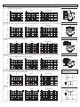
H5DA
SAFETY PRECAUTION This manual uses the following symbols to ensure safe operation of this timer.
MULTI-FUNCTION
DIGITAL COUNTER / TIMER
WARNING
CAUTION
User's Manual
Warnings are indicated when mishandling this product might result in death or serious injury
to user.
Cautions are indicated when mishandling this product might result in minor injury to the user,
or only physical damage to the timer.
WARNING
RESTRICTIONS ON USE
ΘNote this incorrect wiring of this product can damage it and lead to other hazards. Make sure the product has
been correctly wired before turning the power ON.
ΘBefore wiring, or removing / mounting the product, be sure to turn the power OFF. Failure to do so might cause
electric shock.
ΘDo not touch electrically charged parts such as the power terminals. Doing so might cause electric shock.
ΘDo not disassemble the product. Doing so might cause electric shock or faulty operation.
When using this product in applications
that require particular safety or when
using this product in important facilities,
please pay attention to the safety of the
overall system and equipment. Install failsafe mechanisms, perform redundancy
checks and periodic inspections and
adopt other appropriate safety measures
when it is necessary. This product is rated
at Class Ⅱ
.
CAUTION
ΘUse the product within the operating ranges recommended in the specification (temperature, humidity, voltage,
shock, mounting direction, atmosphere and etc.). Failure to do so might cause fire or faulty operation.
ΘFirmly tighten the wires to the socket. Insufficient tightening of the wires to the socket might cause fire.
SPECIFICATIONS
NAMES AND FUNCTIONS OF FACEPLATE
Operating voltage
AC/DC : 12Д48V, AC/DC : 100Д240V
Allowable operating
voltage range
85 ~ 110% of rated operating voltage
Rated frequency
50 / 60Hz
Contact rating
250VAC 5A (Resistive load)
Count speed
MAX 30, 1k, 5k or 10k cps
Power consumption
Approx. 2.5VA
Life
Mechanical : 5,000,000 times, Electrical : 100,000 times
LEDs
Ambient temperature -10Д+50°C
Ambient humidity
MAX 85% RH
Weight
Approx. 118g
Upper display
COUNTER: Counting indicator
TIMER: Timming indicator
Out1, Out2: Control output 1, 2 indicator
RESET: Reset indicator
CP1, CP2: Signal input 1, 2 indicator
Start: Start signal input indicator
Gate: Gate signal input indicator
K/P: Key protection indicator
Set1, Set2: 1st, 2nd set value indicator
Total: Total value indicator
hr, min, sec: Time unit indicator
Display present value or setup items
Lower display
Display set value or parameters
key
Shift cursor or switch mode
key
Increment and decrement numeric values,
and switch betwen Set1/Set2 display
ʳʳʳʳʳkey
Reset the output, or save the set value then back to the operation mode
SETTING PROCEDURE
COUNTER OR TIMER'S VALUES RESET
POWER ON
SWITCH TO THE MODE SETTING STATUS
or
ʳʳ3 Sec
SWITCH TO THE NEXT MODE
ON / OFF Key protect
SAVE AND BACK TO THE OPERATION STATUS
ʳ3 Sec
Counter:
1.INPUT MODE
UP
DOWN
UP/DOWN A
UP/DOWN B
UP/DOWN C
2.OUTPUT MODE
Mode N
Mode F
Mode C
Mode R
5.COUNT SPEED
30 cps
1k cps
5k cps
10k cps
6.MINIMUM RESET TIME
9.KEY PROTECTION LEVEL
Lock function key
+ 3Sec
Lock reset key
Lock preset value key
Lock all key
10.POWER OFF MODE
Mode K
Mode P
Mode Q
Mode A
20mS
1mS
Power off reset
Power off memory
3.OUTPUT 2 TIME
0.01S
0.05S
0.1S
0.2S
0.5S
1S
2S
5S
10S
20S
4.OUTPUT 1 TIME
Hold
0.01S
0.05S
0.1S
7.DECIMAL POINT
999999
99999.9
9999.99
999.999
8.PRESCALE VALUE
11.NPN/PNP INPUT MODE
12.FUNCTION MODE
nPn
PnP
0.2S
0.5S
1S
2S
5S
10S
20S
Mode B
Mode B1
Mode B2
Mode C
Mode D
Mode E
Mode F
00.001~99.999
Counter
Timer
Timer:
2.UP / DOWN MODE
1.TIME RANGE
999.999S
9999.99S
99999.9S
999999S
4.OUTPUT TIME
Hold
0.1S
0.5S
1S
99M59.99S
999M59.9S
99999.9M
999999M
5.INPUT SIGNAL TIME
5S
10S
15S
20S
8.NPN/PNP INPUT MODE
nPn
PnP
99H99M59S
9999H59M
99999.9H
999999H
20 mS
1 mS
Count up
Count down
6.KEY PROTECTION LEVEL
Lock function key
+ 3Sec
Lock reset key
Lock preset value key
Lock all key
9.FUNCTION MODE
Counter
Timer
Pr oduc t is s u b j e c t t o c h a n g e w i t h o u t n o t i c e .
3.OUTPUT MODE
Mode A
Mode A1
Mode A2
Mode A3
7.OUTPUT CONTACT (Only for H5DA-11 and H5DA-11D)
2C
1A1C
TIMING CHART(COUNTER)
Input Modes and Count Value
Please note: 1. "A" indicates minimum signal width; "B" indicates 1/2 of minimum signal width. Signals may not be counted if the minimums for A and B are not met.
2. H and L
Signal
No-voltage input
Voltage input
H
Short circuit
4.5 ~ 30 VDC
L
Open circuit
0 ~ 2 VDC
Up (increment) mode - Count at rising edge
Down (decrement) mode - Count at rising edge
H
H
CP1
CP1
L
L
A
A
Inhibit
H
A
A
Inhibit
H
CP2
CP2
L
L
n
5
n-1
4
Count
n-2
Count
3
n-3
2
n-4
1
0
n-5
0
0
Up (increment) mode - Count at falling edge
Down (decrement) mode - Count at falling edge
H
H
CP1
CP1
L
L
A
Inhibit
H
A
A
H
CP2
A
Inhibit
CP2
L
L
n
5
n-1
4
Count
n-2
Count
3
n-3
2
n-4
1
n-5
0
0
0
Up/Down A Command input mode
Up/Down B Individual input mode
H
H
CP1
CP1
L
L
A
A
H
H
CP2
CP2
L
L
3
Count
3
2
2
1
0
3
Count
2
2
1
3
2
1
0
0
Up/Down C Phase difference input mode (See note 1.)
2
1
1
0
Note 1. Set the same counting speed for CP1 and CP2 when in Up/Down C mode.
H
CP1
L
CONNECTION
BBBB
H
CP2
L
3
Count
2
3
2
1
0
2
1
0
Output :
One-shot output from Output 1
One-shot output from Output 2
Self-holding output
Self-holding output
H5DA-8
Mode N Output and present value display are maintained until reset.
Up
Down
N type(Surface Mounting):
Use only P2CF-08(8-pin), PF085A(8pin) or PF113A(11-pin) Socket
Y type(Flush Mounting):
Use only Y50 Frame & US-08(8-pin),
P3G-08(8-pin) or P3G-11(11-pin)
Socket
Note 1: For NPN input, select b-1 for Counter
and 8-1 for Timer, Common = 0V
Note 2: For PNP input, select b-2 for Counter
and 8-2 for Timer, Common = +V
Up / Down A.B.C
Input 1
Reset
Preset 2
5
4
CP1/START
RESET
999999
6
3
2
7
1
8
OUT2
Preset 1
Common
0
SOURCE
Output 1
N
L
Output 2
Mode F
H5DA-8B
Present value display runs continuously. Outputs are maintained until reset.
Up
Down
Up / Down A.B.C
Input 2
Input 1
Preset 2
CP2/START
CP1/GATE
RESET
Reset
999999
4
5
6
3
2
7
1
Preset 1
8
OUT2
0
Output 1
Output 2
Common
SOURCE
N
L
TIMING CHART(COUNTER)
Up
Down
H5DA-8M
Up / Down A.B.C
Load
(Sensor)
(-)
DC50mA
(+)
PNP
Reset
CP1/ Input 1 4
START
3
Common
999999
Preset 2
Input 2
Mode C
CONNECTION
Present value is placed in reset start status as soon as count up is reached. The count up is not displayed. Outputs are 1-shot and
operate repeatedly. Output 1 is self-holding, and goes off after expiration of the 1-shot period for Output 2. One -shot time periods
for Output 1 and 2 are independent.
CP2/
RESET
Preset 1
5
6
2
7
1
8
OUT2
NPN
0
Output 1
SOURCE
N
Output 2
Present value is placed in reset start status as soon as count up is reached. Outputs are 1-shot and operate repeatedly. Output 1 is
Mode R self-holding, and goes off after expiration of the 1-shot period for Output 2. One -shot time periods for Output 1 and 2 are independent.
Up
Down
L
H5DA-11
Common
RESET
CP1/START
Up / Down A.B.C
Reset
Input 1
999999
4
3
2
Preset 2
Preset 1
5 6 7
1 11
OUT1
8
9
10
OUT2
0
SOURCE
Output 1
N
L
Output 2
Present value runs continuously. Output 1 is self-holding, and goes off after expiration of the 1-shot period for Output 2. One-shot
Mode K time periods for Output 1 and 2 are independent.
Up
Down
H5DA-11D
RESET
Up / Down A.B.C
CP2/START
Reset
CP1/GATE
999999
Input 2
Input 1
Common
4
3
2
Preset 2
Preset 1
5 6 7
1 11
OUT1
8
9
10
OUT2
0
SOURCE
Output 1
N
L
Output 2
Present value display does not change during 1-shot time period, but reset start status is returned to as soon as count is reached.
Mode P Outputs are 1-shot and operate repeatedly. Output 1 is self-holding, and goes off after expiration of the 1-shot period for Output 2.
One -shot time periods for Output 1 and 2 are independent.
Up
Down
H5DA-11M
Up / Down A.B.C
RESET
Common
Reset
999999
Preset 2
CP2/START
CP1/GATE
Input 2
Input 1
K/P
NPN
Preset 1
(-)
Load
(Sensor)
4
3
2
5 6 7
1 11
8
9
10
OUT2
(+)
0
PNP
DC50mA
SOURCE
Output 1
N
L
K / P : Key Protection
Output 2
Present value runs continuously through 1-shot time period and returns to reset start status immediately afterward. Outputs are
Mode Q 1-shot and operate repeatedly. Output 1 is self-holding, and goes off after expiration of the 1-shot period for Output 2. One -shot
time periods for Output 1 and 2 are independent.
Up
Down
Up / Down A.B.C
Reset
Schematic of H5DA-8M & H5DA-11M
with sensor or contact.
NPN type
TFOTPS
H5DA
999999
+V
Preset 2
Preset 1
Dpoubdu
0
Output 1
Output 2
Mode A Present value and output 1 maintain status until reset. Output 1 and 2 operate independently.
Up
Down
Up / Down A.B.C
TFOTPS
H5DA
Preset 1
Dpoubdu
Preset 2
0V
PNP type
Reset
999999
JOQVU
+V
JOQVU
0
Output 1
Output 2
0V
TIMING CHART(TIMER)
A
A-1
Signal ON delay 1
A-2
Signal ON delay 2
(Timer resets when power comes ON.)
(Timer resets when power comes ON.)
Power ON delay 1
(Timer resets when power comes ON.)
SOURCE
SOURCE
Start
Start
Start
Gate
Gate
Gate
Reset
t
Reset
t
Timing starts when the start signal goes ON, and is reset
when the start signal goes OFF. *Note1
The control output is controlled using a sustained or oneshot time period.
B
Power ON delay 2
Timing starts when the reset input goes OFF.
The start signal disables the timing function (ie., same
function as the gate input).
The control output is controlled using a sustained or
one-shot time period.
B-1
Repeat cycle 1
(Timer resets when power comes ON.)
(Timer dose not reset when power comes ON.)
Repeat cycle 2
(Timer dose not reset when power comes ON.)
SOURCE
SOURCE
Start
Start
Start
Gate
Gate
Gate
Reset
t
t
a
Timing starts when the reset input goes OFF.
The start signal disables the timing function (ie., same
function as the gate input).
The control output is controlled using a sustained or
one-shot time period.
B-2
Repeat cycle ON start
(Timer resets when power comes ON.)
SOURCE
Reset
Reset
Control output
Set value
UP
0
Set value
DOWN
0
Control output
Set value
UP
0
Set value
DOWN
0
Timing starts when the start signal goes ON. *Note1
The status of the control output is reversed when time is up
(OFF at start).
Timing starts when the start signal goes ON. *Note1
The status of the control output is reversed when time is up
(OFF at start).
t-a
Control output
Set value
UP
0
Set value
DOWN
0
C
D
Signal ON/OFF delay
(Timer resets when power comes ON.)
Signal OFF delay
(Timer resets when power comes ON.)
SOURCE
SOURCE
Start
Start
Start
Reset
Reset
Gate
Control output
Set value
Control output
Set value
UP
UP
SOURCE
Reset
0
Set value
0
Set value
DOWN
DOWN
0
0
Timing starts when the start signal goes ON. *Note1
The status of the control output is reversed when time
is up (OFF at start).
E
Interval
(Timer resets when power comes ON.)
SOURCE
t
Control output
Set value
UP
0
Set value
DOWN
0
Control output
Set value
UP
0
Set value
DOWN
0
Timing starts when the start signal goes ON. *Note1
The control output is controlled using a sustained or
one-shot time period.
A-3
Reset
t
Control output
Set value
UP
0
Set value
DOWN
0
SOURCE
Timing starts when the start signal goes ON or OFF.
The status of the control output is ON when the start
signal goes ON or OFF.
F
Control output
Set value
UP
0
Set value
DOWN
0
The control output is ON when the start signal is ON
(except when the power is OFF or the reset is ON).
The timer is reset when the time is up.
Cumulative
(Timer does not reset when power comes ON.)
SOURCE
Start
Start
Gate
Gate
*Note1. While the start signal is ON, the timer
starts when power comes ON or when
the reset input goes OFF.
Reset
Reset
Control output
Set value
UP
0
Set value
DOWN
0
Control output
Set value
UP
0
Set value
DOWN
0
Timing starts when the start signal comes ON. *Note1
The control output is reset when time is up.
Start signal enables timing (timing is stopped when the start
signal is OFF or when the power is OFF)
A sustained control output is used.
DIMENSION(mm)
H5DA + Y-50 + US-08
45 +0.5
-0
45 +0.5
-0
H5DA
45 +0.5
-0
ANLY ELECTRONICS CO., LTD.
http://www.anly.com.tw
45 +0.5
-0
M-H5DA-I-A
Printed in Taiwan

![H8DA(M)JA [轉換].ai - Anly Electronics Co., Ltd.](http://vs1.manualzilla.com/store/data/005792054_1-e40506c7505a129d0c559401a2fa00b1-150x150.png)


![H5KLR(M)MA [轉換].ai - Anly Electronics Co., Ltd.](http://vs1.manualzilla.com/store/data/005903580_1-5f70c7fcf57a7272a97f3054b230f775-150x150.png)