1
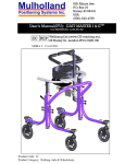
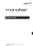
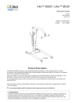
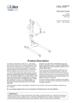
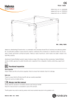
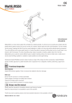
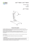
Sabina 200™
Instruction Guide
English
7EN155105-04
2012-03-15
Applies to the following models:
Sabina 200
Prod. No. 2020020
Product Description
The Sabina 200 sit-to-stand lift is especially designed
for people who have difficulty in standing up on their
own from a seated position.
Sabina 200 is intended for use with patients who are
able to actively participate in the raising motion. When
standing, they can be moved to a wheelchair or to a
toilet; this gives them standing practice in connection
with the transfer.
Liko has a wide range of sit-to-stand vests, giving
different support depending on the patient’s needs.
For patients with poor balance, we recommend
Sabina SideSupport, which provides the patient
with extra lateral stability during the raising motion,
as well as in the standing position.
In this document, the person being lifted is referred to as the patient, and the person assisting is referred to as
the caregiver.
is a warning triangle used for situations which require extra care and attention.
IMPORTANT!
Read the instruction guide for both the patient lift and lifting accessories before use. Lifting and transferring
a person always involves a certain level of risk. It is important to completely understand the contents of the
instruction guide. The equipment should be used only by trained personnel. Please contact
your Liko/Hill-Rom representative in the event of any uncertainties or questions.
Table of Contents
Safety Instructions.........................................................................2
Definitions......................................................................................3
Technical Data...............................................................................3
Measurements...............................................................................4
Assembly.......................................................................................5
Operation.......................................................................................7
Charging the Batteries...................................................................8
Maximum Load..............................................................................9
Recommended Lifting Accessories...............................................9
Raising Operations......................................................................10
Simple Troubleshooting...............................................................11
Inspection and Maintenance.......................................................12
NOTE!
This instruction guide contains important information for the user of the product.
All who use the product should review and completely understand the contents of the instruction guide.
Remember to keep the instruction guide in a place where it is always available to those using the product.
Safety Instructions
Before using, make sure that:
• the lift is assembled in accordance with the assembly instructions
• the lifting accessories are properly attached to the lift
• the batteries have been charged for at least 12 hours
• you have read the instruction guides for the lift and lifting accessories
• personnel using the lift are informed of the correct operation and use of the lift.
Before lifting, always make sure that:
•the lifting accessory are selected appropriately in terms of type, size, material and design with regard
to the patient’s needs
• the lifting accessories are not damaged
• the lifting accessory are correctly and safely applied to the patient in order to avoid bodily injury
• the lifting accessory is correctly applied to the sling bar
• the sling bar latches are intact; missing or damaged latches must always be replaced
• the sit-to-stand vest’s straps are properly connected to the sling bar hooks when the vest’s straps have been
fully extended but before the patient is lifted from the underlying surface.
• as a caregiver assure that the patient not are at risk of falling forward or to any side during lifting.
After use, store the lift in forward direction towards a wall and out of reach of unauthorized
Never leave a patient unattended in Sabina 200!
Sabina 200 have been tested by an accredited testing institute and fulfil the requirements specified in the Medical
Device Directive 93/42/EEC, for Class 1 products.
Viking S/Viking XS complies with the requirements in EN ISO 10535:2006, IEC 60601-1, IEC 60601-1-2,
ANSI/AAMI ES60601-1, and CAN/CSA C22.2 no 60601-1.
Under no circumstances must the lift be modified. If you have any questions, please contact Liko/Hill-Rom.
Particular care must be observed when using strong sources of potential disturbance, such as diathermy, etc,
so that diathermy cables are not positioned on or near the lift. If you have questions, please consult the
responsible assistive-device technician or the supplier.
The lift must not be used in areas where flammable mixtures may occur, for example in areas where
flammable goods are stored.
Sabina 200 • 7EN155105-04
2
www.liko.com
Definitions
1
17
2
3
16
15
14
Sabina 200
18
XS
S
M
L
4
13
5
12
6
XL XXL XXXL
19
20
21
11
Forward direction
10
22
9
23
8
7
1. Safety latches
2. Lifting hook
3. Sling bar
4. Motor for lift arm
5. Lower-leg support (adjustable)
6. Foot rest (removable)
7. Front wheel
8. Base
9. Rear wheel with brake
10. Motor for base-width adjustment
11. Locking handles
12. Cable for hand control
13. Hand control
14. Control unit with built-in battery
15. Lift mast
16. Manoeuvering handle
17. Lift arm
18. Holder for quick reference guide with
colour code for sling sizes
19. Emergency stop
20.
LED (yellow light) - charger connected
21.
LED (green light) - lift activated
22. Emergency lowering (electrical)
23. External charger
Technical Data
Powder-painted steel.
Operating forces
of controls:
Buttons on hand control: 4 N
Button on display: 4 N
Weight:
Total: 42 kg (93 lbs.)
Heaviest removable part: 23 kg
(50 lbs.)
Electrical data:
24 V
Intermittent
power:
Wheels:
Standard front: 75 mm (2.9 inch)
twin wheel.
Standard rear: 75 mm (2.9 inch)
twin wheel.
Int. Op 10/90, active operation max
2 min. Only 10 % of a given length
of time may be active, yet no more
than 2 min.
Batteries:
2 x 12 V, 2.9 Ah. valve-regulated
lead-acid gel-type batteries. New
batteries are provided by your Liko
representative.
CH01. 100-240 VAC, 50-60 Hz,
max. 500 mA.
Maximum load:
160 kg (350 lbs.)
Material:
Foot rest:
Removable.
Lower-leg
support:
Adjustable height and depth.
Removable.
Battery charger:
Turning diameter
1250 mm (49.2 inch)
Emergency
lowering device:
Electrical.
Lifting interval:
795 mm (31.3 inch.)
Lifting speed
(without load):
Motor for base24 V, 5 A, permanent magnetic
width adjustment: motor.
Lift motor:
24 V, 9.2 A, permanent magnetic
motor with mechanical safety
mechanism.
20 mm/sec (0.9 inch/sec)
Sound level:
42 dB(A)
Protection class:
IPX4
The device is intended for use indoors.
Type B, in accordance with the electrical shock
protection class.
Class II equipment.
Sabina 200 • 7EN155105-04
3
www.liko.com
Measurements
Lateral view
M
N
Amax.
O
Amin.
E
600 mm
L
Ref. 1
B3
B1
Overhead view
F F1
B2
B
C D
D1
700 mm
Max. reach of lift arm
Ref. 2
D2
Table of measurements
A max*
A min*
Measurements in mm.
C
D
E*
B1
B2
B3**
1750 1650 1150 1050 1160 865
575
190 1120 680 1040 550
max
min
max
min
B
max
min
max
min
L*
D1
D2**
890
215 1010 910
max
min
F
F1
105
25
max
min
1705 810
M
N
O
700
287
322
Measurements in inch.
A max*
max
min
A min*
max
min
C
B
68.9 64.9 45.2 41.3 45.6
B1
B2
B3**
34
22.6
7.4
max
44
D
min
max
E*
min
26.7 40.9 21.6
D1
D2**
35
8.4
max
L*
min
39.7 35.8
F
F1
4.1
1
max
67
min
M
N
O
31.8 27.5 11.3 12.6
*Different measurements depending on the height-setting position, please see ”Assembly”, p. 5. Note! The measurements are
based on the lift being equipped with standard sling bar and standard wheels. When changing to other lifting equipment or
wheels, check that the lift still achieves desired lifting height.
** Reference measurement according to Standard EN ISO 10535:2006.
Sabina 200 • 7EN155105-04
4
www.liko.com
Assembly
Before assembly, make sure you have the following parts:
• Lift mast with lift arm, control unit and sling bar
with safety latches
• Base with locking handles
• Hand control with cable
• Foot rest and frame for the foot rest
• Battery charger and cable lid with screws (2 pcs)
• Lower-leg support
• Bag with plug for the charger, quick reference
guide and instruction guide.
Individual adjustment of lifting height
Height of patient Position
< 170 cm (67 inch.) 1
160-190 cm (63-74.8 inch.)2
> 180 cm (70.9 inch.)
3
1
2
3
1. Lock the two rear wheels. Remove the locking
handles on the lift mast. Then place the lift mast
in the foot of the base.
2. When the lift mast is secured in the base, the lifting
height may be adjusted to three different levels.
Choose one of the three holes. The choice of setting
depends on the height of the patient (see illustration
above). The distance between the holes is 5 cm
(2 inch.)
3. Use the included locking handles to secure the lift
mast to the base.
4. Tighten the locking handles and then adjust them
so they point downwards.
B
3
A
5. Mount the lower-leg support into the bracket. Wheel
A is used to adjust the depth, i.e. the distance to the
patient’s lower leg. Wheel B is used to adjust the
lower-leg support’s height setting. Carefully tighten the
wheels after adjustment.
Sabina 200 • 7EN155105-04
5
2
1
6. Connect the cables as follows:
- Cable from lift motor to socket 1
- Cable from motor for base-width adjustment to
socket 2
- Cable from hand control to socket 3.
www.liko.com
7. Thread the cables through the opening in the cable
lid. Push the lid up and secure with a screw driver
and the accompanying screws (2 pcs).
8. Place the quick reference guide in the holder on
the lift mast.
1
2
10. Charge the battery by plugging the charger cable
into the connector cable. Then plug the charger
cable into an electric outlet (100-240 V AC).
The battery is fully charged after approx. 12 hours.
9. R
elease the emergency stop by turning the button in
the direction indicated by the arrows on the button.
After assembly, make sure that:
• the base-width adjustment works
•the lift charges.
•the motion of the lift arm corresponds to the buttons
on the hand control
•the electrical emergency lowering device works
• wheel brakes work properly
Sabina 200 • 7EN155105-04
6
www.liko.com
Operation
Hand control
Sabina 200 is manoeuvred with the push
buttons on the hand control.
For raising and lowering the lift arm, push
the button with the respective arrow. The
direction in which the arrows are pointing
applies when the hand control is held as
shown in the picture. For base width widening
and narrowing, push
and respectively.
The movement ceases as soon as the push
buttons are released.
For emergency stop:
Press the red button on
the control unit.
Resetting the emergency stop:
Release the emergency stop by
turning the button in the direction
indicated by the arrows on the
button.
Lock
Unlock
Locking the wheels
The rear wheels can be locked to prevent rotating and
turning. To lock the wheels, push down the lock pedal
with your foot. To unlock the wheels, lift up the lock
pedal with your foot.
During raising, the wheels should be unlocked so that
the lift can be moved to the patient’s centre of gravity.
Electrical emergency lowering
The lift arm is lowered electrically by keeping the
button on the control unit pressed in.
Locked wheels during raising can increase the
risk of tipping.
Never move the lift by pulling on the actuator!
Installation of Latches
After installation, check that the latch locks
and runs freely in the sling bar hook.
Sabina 200 • 7EN155105-04
7
www.liko.com
Charging the Batteries
A
For maximum battery life, batteries must be charged
regularly. We recommend charging the batteries after use
of the lift or every night. If the lift is not used every day, we
recommend pushing in the emergency stop after use, in
order to turn off the current and save battery power. Ensure
that the lift is fully charged before pushing the emergency
stop.
A yellow LED (A) on the control unit’s display is lit while the
charger is connected to a wall socket. Maximum charge is
achieved after approx. 12 hours. When the batteries are
fully charged, the charger automatically switches to trickle
charging.
When the battery capacity is low (when approx. 2-10 lifting
cycles remain), an acoustic signal is emitted. In this case,
the lift should be charged as soon as possible.
Never charge batteries in a wet area.
The lift cannot be charged with the emergency stop
engaged.
Charging procedure
With external charger:
1
1. Connect the charger cable to the charging outlet under the
control unit.
2. Connect the charger to an electrical outlet (100-240 V AC).
2
hen the charger is connected, a LED displays:
W
- a yellow light during ongoing charging
- a green light during trickle charging.
NOTE! The lift cannot be used when the charger cable is plugged into an electric outlet.
Sabina 200 comply with the Directive 2002/96/EC on waste electrical and electronic equipment.
Old batteries are to be deposited at the nearest recycling facility in accordance with local regulations or
given to personnel authorized by Liko/Hill-Rom.
Sabina 200 • 7EN155105-04
8
www.liko.com
Maximum Load
Different allowable maximum loads may apply to the different products in the assembled lift unit: lift, sling bar, sitto-stand vest and any other accessories used. For the assembled lift unit, the maximum load is always the lowest
maximum load rating for any of the components. For example, a Sabina 200 that is approved for 160 kg (350 lbs)
can be equipped with a lifting accessory that is approved for 200 kg (440 lbs). In this case, the maximum load of
160 kg (350 lbs) applies to the assembled lift unit. Study the markings on the lift and lifting accessories or contact
your Liko/Hill-Rom representative if you have any questions.
Recommended Lifting Accessories
Using other lifting accessories than those recommended can entail a risk.
Below is a description of recommended lifting accessories for Sabina 200. Also, for further guidance, study the
instruction guide for the sit-to-stand vest or the lifting accessory, respectively.
Contact your Liko/Hill-Rom representative or visit www.liko.com for advice and information on Liko’s product range.
Sabina SideSupport
Sabina SideSupport is an accessory for patients
with reduced lateral stability.
Prod. No. 2027101
Sabina Heel Support Heel supports are used if the patient’s feet need to
be fixed to the foot rest. Foot straps are included.
Prod. No. 2027011
Be aware of any decreased mobility and/or the
risk of hyperextension of the knee joints when using
Sabina Heel Support.
Calf strap Prod. No. 20290022
SeatStrap SlingBarProd. No. 2027006
Sabina SeatStrap
Prod. No. 3591115
The SeatStrap is an accessory that facilitates the first
part of the raising motion. The SeatStrap is connected to
a SeatStrap SlingBar, which helps the user move the seat
up when raising. In standing position, the SeatStrap can be
easily disconnected so that it is not in the way when, e.g.,
going to the toilet.
Sabina 200 • 7EN155105-04
9
www.liko.com
Raising Operations
Before using Sabina 200, it is important to make a custom adjustment of the lifting height. See page 5.
For Sabina 200 there are three different sit-to-stand vests to choose between: Liko SupportVest Mod. 91 and Liko
SafetyVests Mod. 93 and 94. Below is a description on how SupportVest Mod. 91 is used. See the instruction
guide for the respective sit-to-stand vest for further information.
2. Raise the sling bar about 10–20 cm ( 3.9-7.9 inch.)
The patient grabs the sling bar. Continue the lifting
procedure. If the patient leans backwards during
raising, the raising will be made easier, preventing
the vest from sliding up. The height to which the lift
should proceed varies from person to person.
Before the patient is lifted from the underlying
surface, but when the straps have been fully
extended, make sure the straps are properly
connected to the sling bar.
1. Place Sabina 200 in front of the patient.
Adjust the width of the base. Place the feet in the
middle of the foot rest with the lower legs parallel to
the lower-leg support. Adjust the height and depth
of the lower-leg support as needed for comfortable
support below the kneecap.
Place the sit-to-stand vest around the patient in
accordance with the instruction guide for the vest.
Connect the straps of the sit-to-stand vest’s to the
sling bar hooks.
3. F
or a more upright position, continue the lifting
motion to the uppermost position. For maximum
comfort, the lift mast should be affixed to the base
in the best possible of the three fastening holes.
See page 5.
When lowering the lift arm, the patient must
follow the lifting motion downwards. This is
facilitated if the patient leans backwards.
Sabina 200 • 7EN155105-04
10
www.liko.com
Simple Troubleshooting
The lift does not work up/down.
Base-width adjustment does not work
(in/out).
1. Make sure that the emergency stop is not
engaged (page 7).
2. Make sure that the control unit cables are
connected correctly (page 5).
3. Make sure that the charging cable is not
connected to an electric outlet.
4. Check the battery voltage (page 8).
5. If the problem persists, please contact
Liko/Hill-Rom.
The charger doesn’t work.
1.Make sure that the emergency stop is not
engaged (page 7).
2.Check that the electric outlet is powered.
3.Check that the charging cable is correctly
connected (page 8).
4. If the problem persists, please contact
Liko/Hill-Rom.
The lift stops in the high position.
1. Make sure that the emergency stop is
not engaged (page 7).
2.Use the selected electrical emergency
lowering to lower the patient onto a firm
surface (page 7).
3. Check the battery voltage (page 8).
4.
If the problem persists, please contact
Liko/Hill-Rom.
If you hear unusual sounds.
Contact Liko/Hill-Rom.
Sabina 200 • 7EN155105-04
11
www.liko.com
Inspection and Maintenance
Care and maintenance
For trouble-free use, certain details should be checked each day the lift is used:
• Inspect the lift and check to make sure that there is no external damage.
• Check the sling bar attachment.
• Check the functionality of the latches.
• Check raising, lowering and base-width adjustment.
• Check to make sure that the emergency lowering functions.
• Charge the batteries each day the lift is used and make sure the charger works.
When necessary, clean the lift with a moist cloth, using common surface cleaners or disinfectants and check
that the wheels are free from dirt and hair. NOTE! Do not use cleaning agents that contain phenol or chlorine,
since these can damage aluminium and polyamide material.
The lift should not be exposed to running water.
Service
Sabina 200 should be inspected at least once a year.
Periodic inspection, repairs and maintenance may only be carried out in accordance with Liko service
manuals, by authorized Liko service personnel and using original Liko spare parts.
Expected Lifetime
The product has an expected lifetime of 10 years during correct use and with maintenance and periodic inspection
carried out in accordance with Liko's instructions.
Transport and storage
During transportation, or when the lift is not to be used for a long time, the emergency stop should be engaged.
The environment where the lift is transported and stored should have a temperature of 10 to 40 °C (50–104 °F)
and a relative humidity of 30 to 75 % (86–167 °F). The air pressure should be 700–1060 hPa.
Recycling
For instructions on how to recycle your Liko product, please visit our website: www.liko.com.
Product changes
Liko’s products undergo continuous development, which is why we reserve the right to make product changes
without prior notice. Contact your Liko/Hill-Rom representative for advice and information about product upgrades.
Design and Quality by Liko in Sweden
Liko is quality certified in accordance with ISO 9001 and its equivalent for the medical device industry, ISO 13485.
Liko is also certified in accordance with environmental standard ISO 14001.
w w w . l i k o . com
Manufacturer:
Liko AB
SE-975 92 Luleå
Sweden
[email protected]
© Copyright Liko AB 2012-03
Service agreement
Liko offers the opportunity to enter into service contracts for the maintenance and regular inspection of your Liko
product.