1
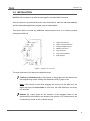
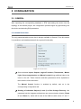
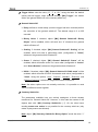
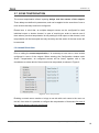
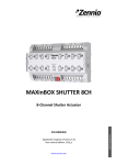
MINiBOX 25
1.2 INSTALLATION
MINiBOX 25 connects to the KNX bus through the on-board KNX connector.
Once the device is provided with power from the KNX bus, both the individual address
and the associated application program may be downloaded.
This device does not need any additional external power since it is entirely powered
through the KNX bus.
1.
Output LED Indicator.
2.
Output Control Pushbutton.
3.
Analogue-Digital Outputs.
4.
KNX Bus Connector.
5.
Prog./Test LED.
6.
Prog./Test Pushbutton.
7.
Relay Outputs.
Figure 1. MINiBOX 25. Elements
The main elements of the device are described next.
Test/Prog. Pushbutton (6): a short press on this button sets the device into
the programming mode, making the associated LED (5) light in red.
Note: if this button is held while plugging the device into the KNX bus, the
device will enter into safe mode. In such case, the LED will blink in red every
0.5 seconds.
Outputs (7): output ports for the insertion of the stripped cables of the
systems being controlled by the actuator (see section 2.3). Please secure the
connection by means of the on-board screws.
http://www.zennio.com
Technical Support: http://zennioenglish.zendesk.com
4