1
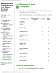
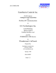
Industrial Ovens An ISO 9001:2008 Registered Company PROGRAM EDITING INSTRUCTION GUIDE NANODAC TEMPERATURE CONTROLLER/ RECORDER This guide is provided by LEWCO, Inc. to assist its customers in becoming familiar with how LEWCO Inc. sets up and uses the Eurotherm Controllers to test equipment prior to shipping. This document does not replace respective Eurotherm user’s manuals and anyone using any of the Eurotherm products mentioned here is responsible for obtaining and understanding the user’s manual before using any of these controllers. The user is responsible for setting up and configuring these devices to meet their own application requirements, not limited to but including adjusting set points, and setting up alarms. LEWCO, Inc. can offer some technical assistance with the minimum setup and configuration to enable the user to get started; however, Eurotherm (800-849-5655), or GC Controls (440-779- 4777) can provide the best possible assistance in most technical matters regarding their products. If you do not have a manual for your controller or just wish to view an online version of it, please use the following link: http://www.eurothermonline.com/search?searchwords=manuals&searchsmall_4920= NANODAC: The Nanodac is a 1/4-DIN controller/ programmer/ recorder. BUTTON LEGEND: EDITING PROGRAMS: Press the PAGE button A menu window will open, use the UP and DOWN arrows until HOME is highlighted and hit the SCROLL button. This will take you to the home screen. Use the UP and DOWN arrows to scroll through the screens until the program screen is shown as in Figure 1. 1 Industrial Ovens An ISO 9001:2008 Registered Company PROGRAM EDITING INSTRUCTION GUIDE NANODAC TEMPERATURE CONTROLLER/ RECORDER Figure 1: Program Screen Figure 2: Program Edit Screen Press the SCROLL button. The MODE field will highlight yellow. Press the UP arrow the program edit icon in the right corner will be highlighted. Press SCROLL button again and the program edit window will open see Figure 2. 2 Industrial Ovens An ISO 9001:2008 Registered Company PROGRAM EDITING INSTRUCTION GUIDE NANODAC TEMPERATURE CONTROLLER/ RECORDER Fields on this screen include: NOTE: Not all fields will be available. Availability depends upon the configuration of the controller. Operation allows the user to select one of the following o Load. Opens the program store and allows the user to select a program to be loaded. o Store. Allows the current program to be saved to the internal program drive. o Delete. Allows the selected program to be deleted. o Delete All. Deletes all programs. o Copy. Copies the selected program for ‘pasting’ either from the internal drive to the USB device, or vice-versa. o Copy All. As above; for ‘Copy’, but copies all the programs in the selected directory. Status shows the status of the previous operation o Success. Previous operation was successful. o Failed. Previous operation failed. o Loading. The program is loading. o Copying. The program copy process is underway. o Deleting. The relevant program is being deleted. Program is the name of the program currently loaded. Holdback Style Appears only if ‘Holdback’ is enabled in the Programmer. Can be set to either o Program: Holdback applies to all appropriate segments. o Per Segment: Holdback enabled on a segment by segment basis NOTE: Holdback pauses the program (freezes the Programmer setpoint (PSP) and the time remaining parameters) if the difference between the Process value (PV) and the Programmer Set Point PSP exceeds a user-specified amount (Holdback value).The program remains paused until the PV returns to within the specified deviation. In ramp or step segments, holdback indicates that the PV is lagging the SP by more than the specified amount and that the program is waiting for the process to catch up. In a dwell segment, holdback is used to guarantee that a work piece stays at set-point within a specified tolerance for the specified dwell duration Ch1 Holdback appears only if ‘Holdback Style’ (above) is set to ‘Program’. o Off: Holdback is disabled o Low: Holdback is entered when PV < (PSP - Holdback Value) o High: Holdback is entered when PV > (PSP + Holdback Value) o Band: Holdback is entered when PV < (PSP - Holdback Value) or PV > (PSP + Holdback Value) Ch1 Holdback value is the value to be used in triggering holdback. 3 Industrial Ovens An ISO 9001:2008 Registered Company PROGRAM EDITING INSTRUCTION GUIDE NANODAC TEMPERATURE CONTROLLER/ RECORDER Ch2 Holdback as for Ch1 Holdback, above but for channel 2 Ramp Style applies to all ramp segments in the program. Ramp Style can be edited only when the program is in Reset mode. Set points, rates, times etc. are set in the individual segment configurations Rate. A Ramp Rate segment is specified by a target set-point and the rate at which to ascend/descend to that set-point. Time. A Ramp Time segment is specified by a target set-point and a time in which to achieve that set-point. Ch1 Ramp Units Select ‘Per Second’, ‘Per Minute’ or ‘Per Hour’ for ramp timing units. Ramp Units can be edited only when the program is in Reset mode. Ch2 Ramp Units as for ‘Ch1 Ramp Units’ above. Appears only for two channel programs and allows different ramp units to be selected for the two channels, if required. Ramp Units can be edited only when the program is in Reset mode. SEGMENT CONFIGURATION: At the bottom of the program edit screen are the segment parameters. Use the UP and DOWN arrows to navigate to the segment number field. Press the SCROLL button. Change the segment number to the segment that needs to be edited. Press the SCROLL button to enter. Use the UP and DOWN arrows to select fields. Once the field is highlighted press the SCROLL button to select that field. When a field is open for editing a small up and down arrow will appear on the right end of the highlighted and selected field. Use the UP and DOWN buttons to change to the desired value. Press the SCROLL button to enter and store the change. Figure 3: Segment Configuration 4 Industrial Ovens An ISO 9001:2008 Registered Company PROGRAM EDITING INSTRUCTION GUIDE NANODAC TEMPERATURE CONTROLLER/ RECORDER Segment fields and descriptions are listed below: NOTE: Not all fields will be available. Availability depends upon the configuration of the controller. Segment Number: Select the relevant segment for configuration. Segment Name: Enter a segment name of up to 20 characters. This name will be truncated on the display page if it, together with the program name, are too long to fit the width of the display area. Type: Select a segment type. Default is ‘End’. Options are: o Ramp. For any program, Ramp segments can be either ‘Ramp Rate’ segments or ‘Ramp Time’ segments according to the ‘Ramp Style’ setting described above. See also Ch1(2) Time’ or ‘Ch1(2) Rate’, below o Dwell. The set point is maintained at its current value for the period defined in ‘Duration’ (see below). o Step. A step segment allows a step change to be entered for the target set-points Ch1 TSP and Ch2 TSP. o Wait. A wait segment causes the program to wait for a certain event to occur before continuing. See ‘Wait For’, below. o Go Back. A Go Back segment allows a specifiable number of iterations to be performed of a group of segments. This could be used, for example, to cycle an entire program by having a Go Back segment immediately before the end segment and specifying segment 1 as the ‘Go Back To’ point. Setting ’Cycles’ to ‘Continuous’ causes the program to loop indefinitely, until interrupted by the user. ‘Nested’ loops are not permitted i.e. ‘Go Back’ is not available as a segment type for segments inside an existing GoBack loop. o End. The final segment of a program allows the user to select ‘Dwell’ or ‘Reset’ as the action to be taken at the end of the program (see ‘End Type’, below) 5 Industrial Ovens An ISO 9001:2008 Registered Company PROGRAM EDITING INSTRUCTION GUIDE NANODAC TEMPERATURE CONTROLLER/ RECORDER Ch1(2) TSP Target set point. The value that Ramp or Step segments seek to attain, for channel 1(2). Ch1(2) Rate For Ramp Rate segments, this specifies the speed at which the process value ramps towards the target, for Channel 1(2). The ramp units (per second, per minute, per hour) are set in Ch1(2) ramp units described above. Ch1(2) Time For Ramp Time segments, this allows the user to specify the time to be taken by the segment for the process value to reach the target. Duration For Dwell segments, this allows the entry of the time for which the segment dwells. Go Back To For ‘Go Back’ segments, this defines the number of the segment to which the program is to return. Cycles The number of times the ‘Go Back’ instruction is to be carried out. If set to ‘Continuous’, the program continues until the user intervenes to stop it. End Type Allows the user to select the action to be taken at the end of the program: o Dwell: the set-point is maintained indefinitely and event outputs remain at their configured state. o Reset: the set-point reverts to the value used by the control loop before the program was started and the event outputs return to their default states. Wait For Digital High: Wait segments can be configured to wait for ‘Wait Digital’ to go ‘high’ before allowing the program to continue. Analog 1(2): The segment waits for ‘Wait Analog1(2) to meet an Absolute High or Low, or Deviation High or Low condition before allowing the program to continue. Analog Both: As Analog 1(2) above, but waits for both Channels’ conditions to be true before continuing. Ch1 Wait Select ‘Abs High’, ‘Abs Low’, ‘Dev High’ or ‘Dev Low’ as the wait criterion for channel 1. Appears only if ‘Wait For’ (above) is set to ‘Analog 1’ or ‘Analog Both’. Ch2 Wait Select ‘Abs High’, ‘Abs Low’, ‘Dev High’ or ‘Dev Low’ as the wait criterion for channel 2. Appears only if ‘Wait For’ (above) is set to ‘Analog 2’ or ‘Analog Both’. Ch1(2) Wait Val Enter the trigger value for ‘Ch1(2) Wait’ Ch1(2) Holdback Select ‘Off’, ‘Low’, High’, or ‘Band’ (see description in Program details above). Ch1(2) Holdback Val The value to be used in triggering holdback. 6 Industrial Ovens An ISO 9001:2008 Registered Company PROGRAM EDITING INSTRUCTION GUIDE NANODAC TEMPERATURE CONTROLLER/ RECORDER Ch1(2) PV Event Appear only if ‘PV Events’ have been enabled in the Programmers Features. A PV Event (an analogue alarm on the channel PV) is available for each channel in every segment (excluding Wait and Go Back segment types). The following PV Events are supported: o Off: The PV Event is disabled o Abs High: The event is triggered when the channel PV exceeds PVEvent Val for the relevant channel. o Abs Low: Triggered when the channel PV becomes less than PVEvent Val for the relevant channel. o Dev High: This event is triggered when the channel PV exceeds (PSP + PVEvent Val) for the relevant channel o Dev Low: Triggered when the channel PV becomes less than (PSP - PVEvent Val) for the relevant channel. o Dev Band - This event is triggered when the channel PV differs from the PSP by more than the configured deviation value (either above or below). Ch1 PVEvent Val Appears only if ‘Ch1 PVEvent’ is not ‘Off’. Sets the level at which Ch1 PV Event becomes active. Ch2 PVEvent Val Appears only if ‘Ch2 PVEvent’ is not ‘Off’ and if ‘Channels’ is set to ‘2’ in Programmer Set Up. Sets the level at which Ch2 PV Event becomes active. Ch1 (2) Event Use When PV events become active, they can be used either to Trigger a secondary process or as a simple analogue alarm on the PV input. Appears only if the relevant PV Event parameter is not set to ‘Off’. Ch1 (2) User Val Specifies the User Value for this segment, for channel 1(2). Appears only if ‘User Value’ has been enabled in the Programmer. Event 1 to 8 The number of Events available (Max Events) is defined in the Programmer Set Up. Enabling an event causes the relevant indicator on the display page to be illuminated for the duration of the segment. 7