1
Volume 5 - Integration
HarnesSYS™ - NX Interface
User Manual
HarnesSYS Version r20a
Document Version E
Document status: Release (R) Last modified Date/time: December 18, 2012 18:02
Copyright Notice
The information contained in this manual is believed to be accurate and reliable. However, Israel
Aerospace Industries Ltd. (IAI) assumes no responsibility for any errors, omissions, or
inaccuracies whatsoever.
Information in this document is subject to change without notice and does not represent a
commitment on the part of Israel Aerospace Industries Ltd. (IAI). The software and/or database
described in this document are furnished under a license and/or agreement. The software and/or
database may be used or copied only in accordance with the terms of such license and/or
agreement. It is against the law to copy the software on any medium except as specifically
allowed in the license and/or nondisclosure agreement. The purchaser may make one copy of the
software for backup purposes. No part of this document and/or data base may be reproduced or
transmitted in any form or by any means, electronic or mechanical, including photocopying,
recording, or information storage and retrieval systems, for any purpose other than the
purchaser’s personal use, without the express written permission of IAI.
2012 Israel Aerospace Industries Ltd. All rights reserved.
Proprietary
Document Version E
Printed copy is for reference only
i
Contents
Document Revisions History....................................................................................... vii
Preface............................................................................................................................ ix
Conventions........................................................................................................................ix
About this User Manual ......................................................................................................x
Audience .............................................................................................................................x
Related Documents .............................................................................................................x
Document Organization .....................................................................................................xi
1
Introduction..................................................................................................................... 1
1.1
1.2
Aim and Sub-aims of the HarnesSYS - NX Interface Process. .......................................................1
Terminology .....................................................................................................................................2
2
Installation of HarnesSYS - NX Interface...................................................................... 5
2.1
2.2
2.3
2.4
2.5
Copy Files ........................................................................................................................................5
Set environmental variables.............................................................................................................6
Install HarnesSYS Interface Icon .....................................................................................................8
Check the Installation of HarnesSYS - NX Interface .....................................................................13
Check HarnesSYS Import & Export Folder Definitions..................................................................15
3
NX Implementation of Bundle Structure .................................................................... 18
4
HarnesSYS - NX Interface Process ............................................................................. 19
4.1
4.1.1
Export Parts List.............................................................................................................................21
Export HarnesSYS Parts................................................................................................................21
4.2
4.2.1
4.2.1.1
4.2.1.2
4.2.1.3
4.2.1.4
4.2.1.5
4.2.1.6
4.2.1.7
4.3
4.3.1
4.3.2
4.3.3
4.3.4
4.3.5
Place HarnesSYS Parts in Model ..................................................................................................25
Prepare Electrical and Geometrical Data for NX Parts..................................................................26
Basics.............................................................................................................................................27
Connectors.....................................................................................................................................29
Backshells ......................................................................................................................................40
Adapter Structure ...........................................................................................................................46
Add Task Attribute to Adapter........................................................................................................47
Embedded Clamp Structure...........................................................................................................48
Add Task Attribute to Embedded Clamp........................................................................................49
Route the Geometrical Bundle.......................................................................................................51
Route the Main Path ......................................................................................................................51
Create Branch Segment.................................................................................................................52
Design Flexible Segments for 2D Manufacturing ..........................................................................52
Do Not Participate uncompleted geometry ....................................................................................53
Special End Connector Cases .......................................................................................................54
Example: Process to export Parts & Lugs ..............................................................................22
ii
Document Version E
Printed copy is for reference only
Proprietary
4.3.5.1
4.3.5.2
Route Paths for each Lug individually............................................................................................54
Assign Multiple Terminators at a Single Point ...............................................................................56
4.3.5.3
4.3.5.4
Use named points indicating wire end path ...................................................................................57
Widely Spaced Terminator on single part ......................................................................................59
4.3.5.5
Data Bus Coupler...........................................................................................................................61
4.4
4.4.1
4.4.2
4.4.3
Export Bundle Geometry................................................................................................................62
Create Bundle Geometry File ........................................................................................................65
Define Bundle Variables.................................................................................................................67
Define Bundle Name Parameter ....................................................................................................70
4.4.4
4.4.5
4.4.5.1
NX Error Management Window .....................................................................................................72
Set Parameters to Define Bundle Features ...................................................................................73
Add Task Attributes Option ............................................................................................................73
4.4.6
4.5
4.5.1
4.6
4.6.1
4.7
4.8
4.9
Error Management Window ...........................................................................................................86
Check Bundle Geometry against BTP & Receive Diameters ........................................................87
HarnesSYS: Check Bundle Geometry against BTP ......................................................................88
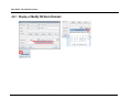
Update HarnesSYS Diameters ......................................................................................................94
Display or Modify NX Stock Diameter............................................................................................95
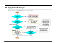
Apply the Bundle Changes ............................................................................................................96
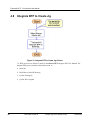
Integrate BTP to Create Jig ...........................................................................................................98
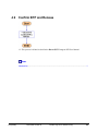
Confirm BTP and Release .............................................................................................................99
Example..................................................................................................................................57
Example..................................................................................................................................59
Example..................................................................................................................................61
Example: 4002-501 ................................................................................................................71
Example name attribute: 4002-501 ......................................................................................78
Glossary of Terms ...................................................................................................... 101
Index ............................................................................................................................ 108
Proprietary
Document Version E
Printed copy is for reference only
iii
List of Figures
Figure 1: Customize Window..............................................................................................................................9
Figure 2: User Command window ....................................................................................................................10
Figure 3: Change Button image window ..........................................................................................................11
Figure 4: Button image window ........................................................................................................................11
Figure 5: Customize window ............................................................................................................................12
Figure 6: Button action window ........................................................................................................................13
Figure 7: Project Default window......................................................................................................................16
Figure 8: Diagram describing the bundle structure ..........................................................................................18
Figure 9: Data flow ...........................................................................................................................................20
Figure 10: Export HarnesSYS™ Screen ..........................................................................................................23
Figure 11: Termination message window.........................................................................................................24
Figure 12: Check the continuity of special lines ...............................................................................................27
Figure 13: Route the Main Path........................................................................................................................51
Figure 14: Two Planar Frames .........................................................................................................................53
Figure 15: Multi Bundle Designator ..................................................................................................................58
Figure 16: Connector Installation......................................................................................................................58
Figure 17: SWD Data Bus ................................................................................................................................61
Figure 18: Data Bus Coupler Connections.......................................................................................................61
Figure 19: Categories of Electrical Tasks.........................................................................................................71
Figure 20: Error Window...................................................................................................................................72
Figure 21: Categories of Electrical Tasks Menu...............................................................................................74
Figure 22: Cue: Enter HARNESS_BUNDLE_NAME value..............................................................................78
Figure 23: Cue: Enter 'HARNESS_CLAMP_MARKER' value........................................................................80
Figure 24: Cue: Enter HARNESS_BRAID_THICKNESS value .......................................................................80
Figure 25: Cue: Enter EMI_GROUP_NAME (HARNESS_RUN_LETTERS) value. ........................................81
Figure 26: HarnesSYS™ Tasks for Protective Devices Menu .........................................................................83
Figure 27: Harness Tasks for Notes Menu.......................................................................................................84
Figure 28: Cue: Enter 'HARNESS_CLAMP_MARKER' value.........................................................................84
Figure 29: Cue: Enter 'HARNESS_BUNDLE_BRAID_THICHNESS' value ....................................................85
Figure 30: Error Window...................................................................................................................................86
Figure 31: Integrate BTP to Create Jig Scheme ..............................................................................................98
iv
Document Version E
Printed copy is for reference only
Proprietary
List of Tables
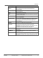
Table 1: Environmental Variables......................................................................................................................6
Table 2: Representation of Basic Connectors by NX objects ..........................................................................30
Table 3: Presentation of Circular Connector by NX objects ............................................................................32
Table 4: Representation of Coupler by NX objects..........................................................................................34
Table 5: Representation of Rectangular Connector by NX objects..................................................................36
Table 6: Representation of single part Widely Spaced Terminator by NX objects..........................................38
Table 7: Representation of Straight Backshell by NX objects .........................................................................40
Table 8: Representation of Circular Angled Backshell by NX objects ............................................................42
Table 9: Representation of Rectangular Angled Backshell by NX objects......................................................44
Table 10: Representation of Adapter by NX objects........................................................................................46
Table 11: Representation of Embedded Clamp by NX objects........................................................................48
Table 12: Example for lug naming conventions...............................................................................................56
Table 13: Categories of Electrical Tasks..........................................................................................................76
Proprietary
Document Version E
Printed copy is for reference only
v
Preface
Document Revisions History
Revision
E
date
December 2012
Change Summary
Minor changes were made to correct errors.
Some chapters and topics were rearranged.
Added "jump links" between topics.
Reference: Mantis No. 7760.
Proprietary
Document Version E
Printed copy is for reference only
vii
Preface
Preface
Conventions
Italic text - is used to indicate a word or phrase, which has a special meaning with respect to
HarnesSYS™, such as the name of a menu or option. Italic text is also used for examples.
Smaller italic text is used for notes and helpful hints; these are also indicated by icons (see
below)
Bold text - Bold text is used for emphasis a word, sentence or paragraph.
Bold italics - Bold italics is used for Procedure Heading.
COURIER - Text printed in Courier font represents text that appears on your screen.
Indicates note
Indicates an example.
Indicates a helpful hint.
Indicates additional information.
Indicates cautionary text or a warning. Both types of text are framed in a box. A
Warning, however, is printed on a raster (gray) and has the title "WARNING!".
Indicates an operation that you, the user, are to perform. Operations in a series are also
numbered.
Indicates a key on your keyboard.
Indicates a path to take. This usually entails selecting a number of options from menus.
Indicates a time consuming operation.
Proprietary
Document Version E
Printed copy is for reference only
ix
THarnesSYS™T - NX Interface User Manual
Indicate Procedure start
Indicates Procedure continue
Indicates what you should see on the screen - the computer's response.
Link to other document.
Indicates the end of the user guide.
About this User Manual
This User Manual describes the HarnesSYS™ - NX Interface Process which enables the Design
and Maintenance of Integrated Electrical-Mechanical Bundle Models.
Audience
This manual is for experienced designers. It explains the Interface Process through all its phases.
However it is not intended to guide the user how to design and manufacture his Project.
Related Documents
This manual is one of the set of manuals that make up the HarnesSYS™ user documentation.
HarnesSYS™ user documentation is organized in the following volumes:
x
Volume 0 - Getting Started
Volume 1 - Schematic Wiring Diagram (SWD)
Volume 2 - 2D Routing/Jig
Volume 3 - Wires
Volume 4 - Parts
Volume 5 - Integration
Volume 6 - Project Management
Volume 7 - Manufacturing.
Volume 8 - Generating Technical Publications.
Document Version E
Printed copy is for reference only
Proprietary
Preface
Volume 9 - Retrofit.
Volume 10 - Utilities
Volume 11 - Importer
Volume 12 - Miscellaneous
Document Organization
This manual includes the following chapters:
Proprietary
Chapter Number
Chapter 1
Title
Introduction
Chapter 2
Installation of
HarnesSYS™ – NX
Interface
This Chapter explains how
to install the USER
FUNCTION.
Chapter 3
NX Implementation of
Bundle Structure
Diagram describing the
bundle structure.
Chapter 4
HarnesSYS™ - NX
Interface Process Flow
Describes the data flow for
concurrent engineering
using HarnesSYS™ and
NX.
Document Version E
Description
Printed copy is for reference only
xi
1
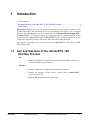
Introduction
In This Chapter:
Aim and Sub-aims of the HarnesSYS - NX Interface Process. .........................................1
Terminology ......................................................................................................................2
HarnesSYS™ bundles may have 3D geometric representations in external mechanical CAD
systems such as NX. This information exists in the mechanical CAD model as part of a digital
Mock-up. These bundle models may be created in NX with the Routing Electrical Application.
The HarnesSYS™ - NX Interface enables concurrent engineering by transferring data in both
directions between HarnesSYS™ and NX. HarnesSYS™ requires geometrical data such as wire
lengths and components locations. NX requires Parts data and segments diameters.
The interface is activated via an icon that activates the HarnesSYS™ - NX Interface USER
FUNCTION in NX.
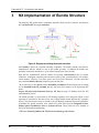
1.1
Aim and Sub-aims of the HarnesSYS - NX
Interface Process.
Aim
Design and Maintain Integrated Electrical-mechanical Bundle Models in a
concurrent engineering environment.
Provide a comprehensive integration methodology and process
Combine the strength of both systems: Logical Data in HarnesSYS™,
geometric data in NX.
Fulfill mechanical and electrical requirements.
Sub-aims
Proprietary
Document Version E
Printed copy is for reference only
1
THarnesSYS™T - NX Interface User Manual
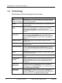
1.2
Terminology
The following are unique terminology for this user manual:
Basic Term
BTP
(Build-To-Package)
2
Description
HarnesSYS™ document that contains all the engineering data for
bundle manufacture using sub-documents such as Wire List, Part
List, 2D-Routing and JIG.
Bundle
Wires and parts that are grouped together to be assembled as one
unit using a JIG.
NX-Interface Export
folder
The folder where the Interface creates files that transfer geometrical
data from NX to HarnesSYS™. It should be the same folder as
HarnesSYS™ Import folder and should be defined by
environmental variables prior to NX activation.(see the Installation
chapter)
NX-Interface
Import folder
This folder contains files that transfer Parts List and segment
diameter data from HarnesSYS™ to NX. It should be the same
folder as HarnesSYS™ Export Folder and should be defined by
environmental variables prior to NX activation. (see detail) (on
page 5)
Centerline Object
A basic routing object such as a single line, spline, Routing
Segment, etc.
Clamp Marker
A point with text that is marked on the manufactured bundle at a
specified location.
Connector Keyway
A line in a circular connector that represents the keyway direction
from the point indicating the wire path termination. This line is
used to calculate the clocking angle symbol for angled backshells
on the JIG.
Device
Auxiliary item such as a clamp, backshell or protective device that is
produced with the bundle.
End-Connector
Wire-End terminator that has a unique name on the aircraft (Ref.
Des.).
Environmental
variables
Variables that are defined in the Window Operating System for the
Interface Program installation. These variables may be defined
while a central NX script is activated or independently on each
workstation.
HarnesSYS™
Export folder
This folder contains files that are used to transfer Parts data and
segment diameters from HarnesSYS™ to NX. It is defined in
HarnesSYS™ in the Project Defaults Form. It should be the same
as the NX-Interface Import folder.
HarnesSYS™
Import folder
This folder contains files that are used to load NX geometrical data
into HarnesSYS™. These files are created by the Interface. It is
defined in HarnesSYS™ in the administrator project default form. It
should be the same as the NX-Interface Export folder.
Document Version E
Printed copy is for reference only
Proprietary
Introduction
Basic Term
Proprietary
Description
names for NX
Objects
These naming conventions are set on NX lines and points to define
the wire paths and other attributes inside standard ElectroMechanical parts.
JIGHarnesSYS
A HarnesSYS™ Form Board drawing document that is used for
bundle manufacture.
Node
Bundle segment junction point.
Note
A marker item that is produced within the bundle and is represented
in the NX model by a point.
Parts List
A list of primary parts and their backshells belonging to a specific
bundle in HarnesSYS™.
Protective Device
A covering that is applied to the bundle such as a metal over-braid,
sleeve or boot. It is represented in NX by points having the same
NX parameter. These points indicate the device edges on the
bundle segments.
Segment
A section of the bundle with uniform wire content.
Widely Spaced
Terminator
A Widely Spaced Terminator is a single reference designator
comprising several independent wire paths representing
HarnesSYS™ terminator pins. Within NX, This is group of NX parts
or Designator Points representing pins of the same EndConnector, where each pin has its own wires path.
Wire Path Routing
A 3D model representation of the bundle routing between its EndConnectors
PLMXML file
A file in PLMXML format that is used to transfer Part data from
HarnesSYS™ to NX...
3d_asc
A file with the 3d_asc extension which is created by the Interface,
and contains geometrical data of the NX bundle. This file is used by
HarnesSYS™ to build the JIG or transfer the diameters back to NX.
Document Version E
Printed copy is for reference only
3
2
Installation of HarnesSYS - NX Interface
In This Chapter:
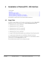
Copy Files .........................................................................................................................5
Set environmental variables ..............................................................................................6
Install HarnesSYS Interface Icon ......................................................................................8
Check the Installation of HarnesSYS - NX Interface .......................................................13
Check HarnesSYS Import & Export Folder Definitions ...................................................15
This installation is suitable for NX6 or NX8 with and without TeamCenter 8.
2.1
Copy Files
The Interface Program Package for NX contains the following files. After the HarnesSYS™
installation process, these files should appear in the ~harness/r20a.00/NX interface folder.
NXinterface/hr_nx6_win7_64_interface.dll
NXinterface/hr_nx6_win7_32_interface.dll
NXinterface/hr_nx6_win7_TC8 32_interface.dll
NXinterface/hr_nx6_win7_TC8 64_interface.dll
NXinterface/hr_nx8_win7_64_interface.dll
hr ugnx6 TC2007 interface.dll (this module works with Windows XP and TeamCenter 2007)
hr ugnx6 interface.dll (this module works with Windows XP without TeamCenter)
This is the NXOPEN module (User Function) for Windows XP, 32 or 64-bit Windows7 which is
executed by the user from the HarnesSYS™ icon in NX.
The user should select the suitable file to his working environment.
Proprietary
Document Version E
Printed copy is for reference only
5
THarnesSYS™T - NX Interface User Manual
2.2
Set environmental variables
Environmental variables define file locations and parameters for the Interface Program.
A. For computer sites with central system support for NX
When NXOPEN module is activated, the environmental variables will be already defined by the NX system Group. This setting
requires one installation per site only.
B. For a single user definition or computer sites where NX management is a performed outside the Computer Center.
Click on the "Start" Microsoft Window button and choose the following menus:
Start
Setting
Control Panel
System
Advanced
Environmental Variables
Before you start NX, install the following compulsory environmental variables:
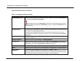
Table 1: Environmental Variables
Environmental Variable Name
Environmental Variable Description
HR_UG_ROUTE_MASTER_STOCK_PRT
Path of *ptb file that contains the PART_NAME definition of the *.prt file loaded by
NX, in order to define stocks in NX Routing Electrical. The *.prt file must be installed
or located previously.
The *.ptb file location: {UGII_EPLIB_TABLE_PATH}\wires_mm.ptb is defined by
NX environmental variable in {UGII_ENV_FILE} .
HR_UG_ROUTE_APPL_VIEW
Define the path of the appropriate ugroute_elec_xx.xml, where xx is inch/metric.
The value of HR_UG_ROUTE_APPL_VIEW should be equal to the value of
{UGII_ROUTE_ELEC_APP_VIEW} which is defined by NX environmental
variable in {UGII_ENV_FILE}.
HR_ROUTE_ELEC_INTERFACE_DIMEN
SION=INCH
Defines what unit will be used in Variable:
HR_UG_ROUTE_MASTER_STOCK_PRT
or
HR_ROUTE_ELEC_INTERFACE_DIMEN
SION=MM
6
Document Version E
Printed Copy is for reference only
Proprietary
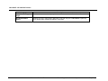
Installation of HarnesSYS - NX Interface
Environmental Variable Name
HR_UG_INTERFACE_EXPORT_DATA
Environmental Variable Description
Defines the export folder where files are stored by the Interface program.
Example: C:\nx2harness\
HR_UG_INTERFACE_IMPORT_DATA
Defines the import folder where files read by the Interface program are located.
Example: C:\harness2nx\
7
Document Version E
Printed Copy is for reference only
Proprietary
THarnesSYS™T - NX Interface User Manual
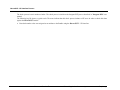
2.3
Install HarnesSYS Interface Icon
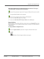
In order to install the HarnesSYS™ Interface icon
follow the following steps:
in the main NX toolbox
Copy the file "User.mtx" from your NX customized environment to
C:\Document and Setting\<user>\Local Settings\Application Data\Unigraphics
Solutions\NX\user.mtx
Open local (without customization) NX (from {UGII_ROOT_DIR}\ugraf.exe)
From the top menu Choose Tools
Choose Commands tab
8
Customize
Choose New Button
Document Version E
Choose New User Command.
Printed copy is for reference only
Proprietary
Installation of HarnesSYS - NX Interface
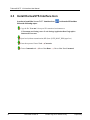
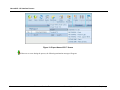
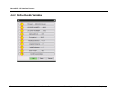
Figure 1: Customize Window
Do not close the Customize window for the next steps.
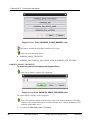
Create a command button by dragging New User Command to any location on the menu
bar or toolbars.
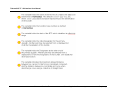
Right click on the created button User Command and the following drop down menu
appears in the displayed menu:
Enter Name: HarnesSYS - The HarnesSYS string will appear in the menu bar instead of
User Command.
Press Enter to save the new command name.
Again, right click on the User Command button and the following drop down menu
appears:
Proprietary
Document Version E
Printed copy is for reference only
9
THarnesSYS™T - NX Interface User Manual
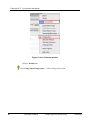
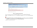
Figure 2: User Command window
Choose: Default Syle
Select Change Button Image option Choose Image Name option.
10
Document Version E
Printed copy is for reference only
Proprietary
Installation of HarnesSYS - NX Interface
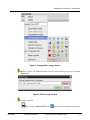
Figure 3: Change Button image window
Browse to choose IAI_HarnesSYS.bmp (The IAI_HarnesSYS.bmp is part of the Manual
Installation).
Figure 4: Button image window
Press OK to confirm.
As a result, the HarnesSYS™ icon
Proprietary
Document Version E
appears in the Command Properties area.
Printed copy is for reference only
11
THarnesSYS™T - NX Interface User Manual
Click the Edit Action button option on the HarnesSYS™ icon in the Commands area.
Figure 5: Customize window
The following menu will appear.
12
Document Version E
Printed copy is for reference only
Proprietary
Installation of HarnesSYS - NX Interface
Figure 6: Button action window
In the "Enter an Action or Use Browse" text box:
Browse for the following .dll
~harness/rxx.xx/NXinterface/hr_nx8_win7_64_interface.dll
In the "Enter Button Message text" box enter: HARNESSYS
Press OK to confirm.
After you finish defining your function
Close NX
Copy C:\Documents and Settings\<user>\Local Settings\Application Data\Unigraphics
Solutions\NX\user.mtx to its place in your customized environment.
Enter NX with your customized environment and check your new function.
The Process above enables the user to run the HarnesSYS™ Interface.
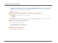
2.4
Check the Installation of HarnesSYS - NX
Interface
This check shows the Creation Date of the Interface and the environmental variables status as
they appear after the HarnesSYS™ - NX Interface installation (on page 5) .
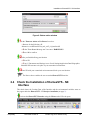
Activate the HarnesSYS™ Interface using the H icon on the NX work space.
Proprietary
Document Version E
Printed copy is for reference only
13
THarnesSYS™T - NX Interface User Manual
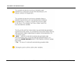
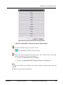
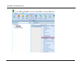
The HarnesSYS™ – NX Interface main window appears:
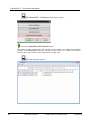
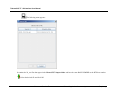
Choose the About HarnesSYS™ Interface option.
This option provides creation date of the module and all possible user-defined environmental
variables of the HarnesSYS™ Interface with their current values. If a variable has not been
defined in the current session it will be shown with an empty value.
The following menu appears:
14
Document Version E
Printed copy is for reference only
Proprietary
Installation of HarnesSYS - NX Interface
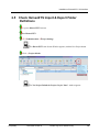
2.5
Check HarnesSYS Import & Export Folder
Definitions
Log in to HarnesSYS™ account.
Run HarnesSYS™.
Administration
Project Settings
The HarnesSYS™ start Session Window appears (with the New Project button
enabled).
Click
Project default
.
The "Set Project Default for Project: Project Name" window appears:
Proprietary
Document Version E
Printed copy is for reference only
15
THarnesSYS™T - NX Interface User Manual
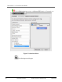
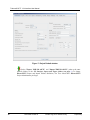
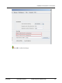
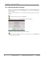
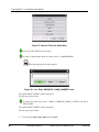
Figure 7: Project Default window
Set the "Export XML/3D ASCII" and "Import XML/3D ASCII" paths to the same
(shared) folders as the NX Interface Import and Export folders (on page 6) To change
HarnesSYS™ Export and Import Folders Definition, The User should have HarnesSYS™
Project Administrator privileges.
16
Document Version E
Printed copy is for reference only
Proprietary
Installation of HarnesSYS - NX Interface
Press OK to confirm the changes.
Proprietary
Document Version E
Printed copy is for reference only
17
THarnesSYS™T - NX Interface User Manual
3
NX Implementation of Bundle Structure
The following NX model and its components should be built in order to transfer data between
NX and HarnesSYS™ using the Interface.
Figure 8: Diagram describing the bundle structure
Each bundle is placed in a separate assembly component. The bundle contains parts that are
manufactured with the bundle as well as the bundle geometry. In addition the bundle may
optionally contain sub-assemblies (e.g. an isolated routing zone in the aircraft).
Parts that are manufactured with the bundle are typically end-connectors such as circular
connectors, rectangular connectors and accessories such as lugs, ground modules, rail modules,
round modules, switches, Coax/Triax splices and Coax/Triax connectors. Circular connectors
may contain Connector Keyway locations represented by line.
These parts may be also devices such as backshells and adapters, External parts such as clamps
are not included in the NX assembly but they may have trace markers on the Jig through NX
points.
Prepare Electrical and Geometrical Data for NX Part (on page 26) Models shows the NX
implementation process.
The bundle geometry is represented by NX Routing Segments, lines and points. When several
segments are connected to the same point, each of them should contain different NX centerline
objects. This data structure may be created by the NX Routing Segments Electrical Application.
In addition the bundle geometry may contain NX points that represent Designator Points,
Widely Spaced Terminators, notes or protective devices. These points are to be installed on
the Jig for the bundle manufacturing.
* The User should be familiar with NX Electrical terminology and activities.
18
Document Version E
Printed copy is for reference only
Proprietary
HarnesSYS - NX Interface Process
4
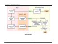
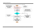
HarnesSYS - NX Interface Process
The products of this process:
1. BTP in HarnesSYS™.
2. Updated model in NX.
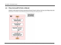
The following scheme describes the data flow for concurrent engineering using HarnesSYS™ and NX.
19
Document Version E
Printed Copy is for reference only
Proprietary
THarnesSYS™T - NX Interface User Manual
Figure 9: Data flow
20
Document Version E
Printed Copy is for reference only
Proprietary
HarnesSYS - NX Interface Process
List of Links:
1.
2.
3.
4.
5.
6.
7.
4.1
Export Parts List............................................................................................... 21
Place HarnesSYS Parts in Model .................................................................... 25
Check Bundle Geometry against BTP & Receive Diameters........................... 87
Update HarnesSYS Diameters ........................................................................ 94
Apply the Bundle Changes............................................................................... 96
Integrate BTP to Create Jig.............................................................................. 98
Confirm BTP and Release ............................................................................... 99
Export Parts List
List of Links
Check HarnesSYS Import & Export Folder Definitions ...................................................15
Check the Installation of HarnesSYS - NX Interface .......................................................13
Export HarnesSYS Parts.................................................................................................21
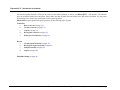
4.1.1 Export HarnesSYS Parts
This function creates a PLMXML file containing Designators and lugs.
Designators are extracted from Part occurrences. This list contains only major parts and backshells.
Lugs are extracted according to term codes and common terminators that may appear on the wires at both ends.
21
Document Version E
Printed Copy is for reference only
Proprietary
THarnesSYS™T - NX Interface User Manual
The export process relates to term codes that are stored directly on the wires.
Term codes may be assigned to wires automatically using "Assign Terminator codes" BTP option or manually using "Wire Single
change" or "Group Change" on the Wire List.
Please note that you may see term codes on the wire reports that are calculated on the fly, but they will be not included in the PLMXML
file generated during the export process.
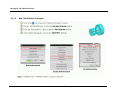
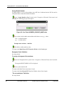
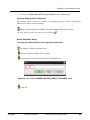
Example: Process to export Parts & Lugs
In HarnesSYS™, choose Interfaces
Export
NX PLMXML - Parts & Lugs
or click (MB3) on the selected BTP from the Workspace.
Choose the "Export
22
NX PLMXML - Parts & Lugs " option
Document Version E
Printed Copy is for reference only
Proprietary
HarnesSYS - NX Interface Process
Figure 10: Export HarnesSYS™ Screen
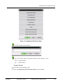
If there are no errors during the process, the following termination message will appear:
23
Document Version E
Printed Copy is for reference only
Proprietary
THarnesSYS™T - NX Interface User Manual
Figure 11: Termination message window
If the process terminated successfully, the file <BTP-Name> .plmxml* will be created in the HarnesSYS™ Export folder.
If "Export
folder.
NX PLMXML - Parts" option is used, the <BTP-Name> -PL. plmxml* file will be created in the HarnesSYS™ Export
If the HarnesSYS™ Export folder and the NX-Interface Import folders are not shared folders (i.e. the file created in HarnesSYS™
Export folder does not automatically appear in the NX-Interface Import folder) then you must manually copy the files created by
HarnesSYS™ in the HarnesSYS™ Export folder to the NX-Interface Import folder.
* PLMXML - An open XML-based file format
24
Document Version E
Printed Copy is for reference only
Proprietary
HarnesSYS - NX Interface Process
4.2
Place HarnesSYS Parts in Model
The bundle assembly contains predefined electro-mechanical NX parts. These parts contains specific feature for installation and wire path
definition. See instructions how to Prepare Electrical and Geometrical Data for NX Parts. After the parts are defined, follow NX
documentation on Assemblies or Electrical Routing applications according to the following work flow:
25
Document Version E
Printed Copy is for reference only
Proprietary
THarnesSYS™T - NX Interface User Manual
4.2.1 Prepare Electrical and Geometrical Data for NX Parts
NX Routing Electrical Ports should be added to NX part in order to enable
continuous routing
The Interface sets interactively HarnesSYS™ names for NX objects such as
"DESIGNATOR_POINT".
These NX lines and points are transferred to HarnesSYS™ and are included in the
drawing segments lengths on JIG. In addition other points indicate the keyway
locations for circular connectors. The Interface uses these points to calculate the
backshell clocking angles in HarnesSYS™.
The model is stored so just the above lines and points will be shown in addition the
model may display other NX object that are not curves or points.
The help lines are invisible. This is the default displayed Reference set.
26
Document Version E
Printed Copy is for reference only
Proprietary
HarnesSYS - NX Interface Process
4.2.1.1
Basics
The HarnesSYS™ - NX interface declares and expects to find some lines, points, ports geometry and part attributes for each ElectroMechanical part. These lines represent wires path or other features (e.g. keyway).
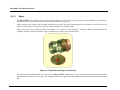
Most lines represent a portion of the wire path inside the various parts. The proper positioning of their end points is critical for the correct
behavior of the interface. In each part, these line segments shall form a continuous path.
When several parts are connected together one another (e.g. "connector with backshell", "connector, adapter and backshell"), the
continuity of these various lines shall be respected without any overlap or gap between the lines.
Figure 12: Check the continuity of special lines
The ports specified in this document are necessary for the HarnesSYS™ - NX interface. The ports shall be located at the end points of the
lines that define portions of the wire paths. It is assumed that the library parts will include additional ports for the placement of the parts in
NX.
27
Document Version E
Printed Copy is for reference only
Proprietary
THarnesSYS™T - NX Interface User Manual
All lines and points should be visible (in the context of the cable assembly) in order to run HarnesSYS™ - NX interface. The interface
does not recognize hidden lines and points. Please make sure that all other lines and points in the NX model are hidden. Use the proper
NX reference set to control the visualization of the required geometry.
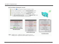
HarnesSYS™ expects predefined special geometry for the following types of parts:
Connectors
a.
Basic connector (on page 30)
b.
Circular connector (on page 32)
c.
Coupler (on page 34)
d.
Rectangular connector (on page 36)
e.
Widely-spaced terminator (on page 38)
Devices
a.
b.
c.
d.
Circular angled backshell (on page 42)
Rectangular angled backshell (on page 44)
Straight backshell (on page 40)
Adapter (on page 46)
Embedded clamp (on page 48)
28
Document Version E
Printed Copy is for reference only
Proprietary
HarnesSYS - NX Interface Process
4.2.1.2
Connectors
List of Links
Basic connector structure................................................................................................30
Circular Connector Structure...........................................................................................32
Coupler part Structure .....................................................................................................34
Rectangular Connector Structure....................................................................................36
Widely spaced terminators on single part Structure........................................................38
29
Document Version E
Printed Copy is for reference only
Proprietary
THarnesSYS™T - NX Interface User Manual
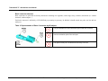
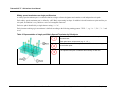
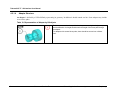
Basic connector structure
Basic connectors are parts that are directly connected to incoming wire segments, such as lugs, relays, switches, mod-blocks (i.e. without
backshell, without adapter…).
Each basic connector is defined by a NX Solid Body representing its geometry. In addition it should contain one point, one line and one
multi port.
Table 2: Representation of Basic Connectors by NX objects
The point indicates the wires termination point inside the connector.
The line indicates the wires path inside the basic connector. It goes
from the termination point to the multi port.
The optional multi-port is located at the extremity of the line.
30
Document Version E
Printed Copy is for reference only
Proprietary
HarnesSYS - NX Interface Process
Add Task Attribute to Basic connector
31
Document Version E
Printed Copy is for reference only
Proprietary
THarnesSYS™T - NX Interface User Manual
Circular Connector Structure
Each circular connector is defined by a NX Body representing its Shape. In addition it should contain one point and two lines.
Table 3: Presentation of Circular Connector by NX objects
The point indicates the wire termination point inside the connector.
The first line indicates the wires path inside the connector from the
wires termination point to the outer face of the connector.
The second line indicates the keyway direction. It should be located
on the same plane as the wires termination point and perpendicular to
the connector axis.
The optional multi-port is located at the extremity of Line 2.
32
Document Version E
Printed Copy is for reference only
Proprietary
HarnesSYS - NX Interface Process
Add Task Attribute to Circular Connector
33
Document Version E
Printed Copy is for reference only
Proprietary
THarnesSYS™T - NX Interface User Manual
Coupler part Structure
Each Coupler part is defined by a NX Body representing its shape. In addition it should contains three aligned lines and two end points of
the middle line.
Table 4: Representation of Coupler by NX objects
Two points indicate the wire termination points inside
the Coupler.
Each point has a unique name (e.g. 1B…,2B...,3S)
These lines represent the coupler on the jig (Form
Board). No wires pass through these lines.
The lines indicate wire path inside the Coupler,
starting from a termination point.
The optional multi-port is located at the extremity of
each line.
34
Document Version E
Printed Copy is for reference only
Proprietary
HarnesSYS - NX Interface Process
Add Task Attribute to Data Bus Coupler
35
Document Version E
Printed Copy is for reference only
Proprietary
THarnesSYS™T - NX Interface User Manual
Rectangular Connector Structure
Each Rectangular Connector is defined by a NX Body representing its shape. In addition it should contain one point, one line, one
optional multi-port as follows:
Table 5: Representation of Rectangular Connector by NX objects
The point indicates the wires termination point inside the
connector..
The line indicates the wires path inside the connector from the
wires termination point to the outer face of the connector.
The optional multi-port is located at the extremity of the line.
Special cases:
a. One wire path and only one backshell if present.
b. Several wire paths.
36
Document Version E
Printed Copy is for reference only
Proprietary
HarnesSYS - NX Interface Process
Add Task Attribute to Rectangular connector
37
Document Version E
Printed Copy is for reference only
Proprietary
THarnesSYS™T - NX Interface User Manual
Widely spaced terminators on single part Structure
A widely spaced terminator part is a connector that has a single reference designator and contains several independent wire paths.
Each widely spaced terminator part is defined by a NX Body representing its shape. In addition it should contain one point and line per
wire path; its definition is very similar to a series of rectangular connectors.
Each wire path is identified by a single character string. i.e. "A",
Each pin name reaching a given terminator is defined according to the following naming pattern: "XXX…", e.g. "A…", "B...", "1…" and
so on.
Table 6: Representation of single part Widely Spaced Terminator by NX objects
For each wires path, a point indicates the wire termination point inside
the terminator.
Each point has a unique name (e.g. A…,B...)
Each line indicates one wires path inside the Terminator, starting from
a termination point.
The optional multu-port is located at the extremity of each line.
38
Document Version E
Printed Copy is for reference only
Proprietary
HarnesSYS - NX Interface Process
Add Task Attribute to Widely spaced terminator on single part
39
Document Version E
Printed Copy is for reference only
Proprietary
THarnesSYS™T - NX Interface User Manual
4.2.1.3
Backshells
Straight Backshell Structure
Each Straight Backshell is defined by a NX Solid Body representing its geometry. In addition it should contain one line.
Table 7: Representation of Straight Backshell by NX objects
The line describes the wires path in the backshell between the
Connector part and multi port.
The optional multi-port is located at the extremity of Line 1.
40
Document Version E
Printed Copy is for reference only
Proprietary
HarnesSYS - NX Interface Process
Add Task Attribute to Straight Backshell
41
Document Version E
Printed Copy is for reference only
Proprietary
THarnesSYS™T - NX Interface User Manual
Circular Angled Backshell Structure
A Circular angled backshell is defined by a NX Solid Body representing its geometry. In addition it should contain two lines.
Table 8: Representation of Circular Angled Backshell by NX objects
These two lines together represent the wires
path though the backshell.
Line 1 is from the connector side to the angle
of the wire path.
Line 2 is from the angle to the outer face where
wires are connected.
These two lines share the same end point (at
the angle).
The optional multi-port is located at the
extremity of Line 2.
42
Document Version E
Printed Copy is for reference only
Proprietary
HarnesSYS - NX Interface Process
Add Task Attribute to Circular Angled Backshell
43
Document Version E
Printed Copy is for reference only
Proprietary
THarnesSYS™T - NX Interface User Manual
Rectangular angled backshell Structure
A Rectangular Angled backshell is defined by a NX Solid Body representing its geometry. In addition it should contain two lines.
Table 9: Representation of Rectangular Angled Backshell by NX objects
These two lines represent together the wires path though
the backshell.
Line 1 is from the angle to the outer face where wires are
connected.
Line 2 is from the connector side to the angle of the
backshell.
These two lines share the same end point (at the angle).
The optional multi-port is located at the extremity of Line
1.
44
Document Version E
Printed Copy is for reference only
Proprietary
HarnesSYS - NX Interface Process
Add Task Attribute to Rectangular angled backshell
45
Document Version E
Printed Copy is for reference only
Proprietary
THarnesSYS™T - NX Interface User Manual
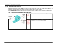
4.2.1.4
Adapter Structure
An adapter is defined by a NX Solid Body representing its geometry. In addition it should contain one line. Some adapters may include
several wires paths.
Table 10: Representation of Adapter by NX objects
The line represents the wires path in the adapter connecting the designator part
and the backshell. Its length should match the length of the wires path through
the adapter.
For adapters with several wires paths, there should be several non-collinear
lines.
46
Document Version E
Printed Copy is for reference only
Proprietary
HarnesSYS - NX Interface Process
4.2.1.5
47
Add Task Attribute to Adapter
Document Version E
Printed Copy is for reference only
Proprietary
THarnesSYS™T - NX Interface User Manual
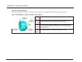
4.2.1.6
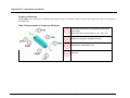
Embedded Clamp Structure
Embedded Clamp Structure typically, clamps are not part of the cable assembly, they are part of the assembly structure. However, for
compatibility with former versions of the interface, it is possible to embed a clamp in the cable assembly.
Each Embedded clamp is defined by a NX Solid Body representing its Geometry. In addition it should contain one line and two points.
Table 11: Representation of Embedded Clamp by NX objects
The line describes the wires path in the Clamp. The length of the
line defines the device width.
Two points along the centerline path. These points indicate the
straight portion of the wires crossing the clamp.
48
Document Version E
Printed Copy is for reference only
Proprietary
HarnesSYS - NX Interface Process
4.2.1.7
49
Add Task Attribute to Embedded Clamp
Document Version E
Printed Copy is for reference only
Proprietary
THarnesSYS™T - NX Interface User Manual
50
Document Version E
Printed Copy is for reference only
Proprietary
HarnesSYS - NX Interface Process
4.3
Route the Geometrical Bundle
Route segments using standard as describe in this manual (on page 25). Follow NX
Documentation on Electrical Routing Application and pay attention to the following items:
a.
Route the MAIN Path (on page 51)
b.
Create Branch Segment (on page 52)
c.
Design Flexible Segments for 2D Manufacturing. (on page 52)
d.
Do Not Participate uncompleted geometry.
e.
Special end-connector cases:
Use named points indicating wire end path. (on page 57)
Route Paths for each Lug individually. (on page 57)
Assign Multiple Terminators at a Single Point (on page 56).
Widely Spaced Terminator on single part. (on page 59)
Data Bus Coupler. (on page 61)
Back to Scheame
HarnesSYS - NX Interface Process........
4.3.1 Route the Main Path
The main path should contain the widest and longest branch segments. It should be routed before
other branches. This is true even if the main path is curved as in the picture below.
The reason for this is because it is drawn without a break on the JIG and such a break can not
occur on the real model.
Figure 13: Route the Main Path
Proprietary
Document Version E
Printed copy is for reference only
51
THarnesSYS™T - NX Interface User Manual
4.3.2 Create Branch Segment
In order to route a branch segment from the main segment, the main segment is subdivided using
a Subdivide Segment NX option, and the second segment is routed from the created Routing
Control Point.
The branch segment may be routed tangentially or normal to the main segment.
It is not recommended to route wires with a sharp angle, e.g. from point A to point B.
Tangential routing may occur when a main segment is split into several branches that are
connected to different connectors on the same box.
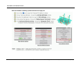
4.3.3 Design Flexible Segments for 2D Manufacturing
The JIG diagram in HarnesSYS™ for a flexible bundle is produced on a planar Jig table where
as the routed branch segment is installed in 3D space. Therefore branch segment directions might
have unexpected twisting angles during the actual installation. This situation may require adding
length to branch segments and might cause unnecessary tension to the bundle supports.
However the routing is usually installed on planar or semi-planar surfaces like Skins, Frames or
Sections. The user may see two such planar frames in the diagram below.
In this case it is recommended that when designing a new routing segment from an existing
planar routing segment, it should start with a vector projected onto that planar surface.
In addition, it is not recommended to connect branches to segments in the area between two
different planar surfaces. In the diagram below, you should not place branches in the designated
area
52
Document Version E
Printed copy is for reference only
Proprietary
HarnesSYS - NX Interface Process
Figure 14: Two Planar Frames
4.3.4 Do Not Participate uncompleted geometry
"DO NOT PARTICIPATE" is an attribute that is set to NX object. Such NX object like NX parts,
points or segments it will not be transferred to HarnesSYS™. This may be used for example
when testing an alternative geometry and therefore there is no need to remove the extra data from
the NX model. See definition details.
Proprietary
Document Version E
Printed copy is for reference only
53
THarnesSYS™T - NX Interface User Manual
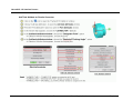
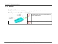
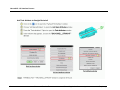
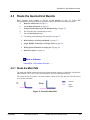
4.3.5 Special End Connector Cases
4.3.5.1
Route Paths for each Lug individually
Several lug may be installed on the same stud. In addition lugs may be installed o different studs or different pins of the same Reference
Designator. In such cases wires for this Reference designator are routed separately creating a widely spaced terminator. The lug name that
is set to each lug contains the Reference Designator name and may contain pin and lug ID according to the following format:
XXXX YYY(ZZ)
where:
XXXX - designator
YYY
ZZ
54
- optional pin name
- optional lug data.
Document Version E
Printed Copy is for reference only
Proprietary
HarnesSYS - NX Interface Process
Such Lugs are transferred from HarnesSYS™ using wire data:
Designator, Pin Name, Term Code and Common Terminator Data.
One or more wires may be terminated on the same lug and several lugs may be installed on the same stud.
Route the path for each lug separately.
The following tabel indicates lugs combinations
55
Document Version E
Printed Copy is for reference only
Proprietary
THarnesSYS™T - NX Interface User Manual
Table 12: Example for lug naming conventions
No.
Cases
Lug in HarnesSYS™
Lug in NX
Format
Example
1.
Ground (one stud)
- One lug per Reference
Designator
xxxx
GND25
2.
Widely Spaced Terminator
(several studs)
One lug per stud
xxxx yyy
TB23 A
Ground or Widely Spaced
Terminator with Common
Terminator
- Common Terminator
Ground or Widely Spaced
Terminator:
- No Common Terminator
3.
4.
Several wires connected to the
same stud without common
terminator
4.3.5.2
TB23 B
xxxx yyy(zz)
- More than one lug per stud.
GND31 - (COM.TERM-YA)
TB23 A (COM.TERM-YA)
xxxx yyy(zz)
GND31 - (WIRE-505)
TB23 A (WIRE-1001)
implies one wire per lug
- More than one lug per stud.
Assign Multiple Terminators at a Single Point
One wire path and only one backshell if present
Several inserts with pin numbering that may be repeated.
Each insert has its own Reference Designator
A single backshell for all the inserts
The connector is defined as "Multiple terminators at a single point".
In this case, several HarnesSYS™ Reference Designators may be mapped to a single NX wire
termination point using wild card <…> which describes one wire path only.
56
Document Version E
Printed Copy is for reference only
Proprietary
HarnesSYS - NX Interface Process
Example
NX component name should be "21YP…" and it will be mapped to HarnesSYS™ Reference Designators 21YPA, 21YPB and 21YPC.
The "Multiple Terminators at a Single Point" method may be also used for several circuit breakers inside a box or for other
designators whose wires are routed and connected only after the bundle is produced.
The reference designator name of such Multiple terminator in HarnesSYS™ contain asterisk for example "21YP*"
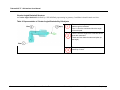
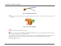
4.3.5.3
Use named points indicating wire end path
Designator Point indicates the end of a wire path and is used in the following cases:
When there is multi bundle designator it belongs to only one bundle in the NX model. The other bundles contain points referring to
this designator.
57
Document Version E
Printed Copy is for reference only
Proprietary
THarnesSYS™T - NX Interface User Manual
Figure 15: Multi Bundle Designator
When it is a complex Reference Designator for example: a Widely Spaced Terminator , where there are number of pins on one NX
part model.
Figure 16: Connector Installation
When the NX model is not defined or not installed
Such a point (with the parameter HARNESS_TASK=DESIGNATOR_POINT) may also be used to temporarily represent a connector
part, that even though the part is not yet defined in NX.
This point should be built at the bundle assembly level. It should contain a named with the HarnesSYS™ Reference Designator Name. In
addition its harness task is defined by object attribute. This object attribute is set to the point using the User Function program.
See definition details. (on page 78)
58
Document Version E
Printed Copy is for reference only
Proprietary
HarnesSYS - NX Interface Process
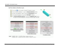
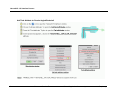
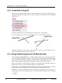
4.3.5.4
Widely Spaced Terminator on single part
Widely Spaced Terminator is a group of pin terminators targeted for a single connector that is widely spaced. The pin names, the lines
and the part attributes appear in predefined parts. Each wire path may contain its own backshell.
Each of the terminators refers to the wires pin name in HarnesSYS™.
Example
In the following example inserts appear as a prefix of the Ref. Des. Pins
HarnesSYS™ pin naming convention:
Insert name appears as a prefix to all its pins.
Widely Spaced Terminator where each insert is defined by a single wire
path ending with a point whose name contains the insert prefix name.
Alternatively, the following solution without Widely Spaced Terminator may be implemented if each insert is considered in
HarnesSYS™ as a separated Reference Designator.
59
Document Version E
Printed Copy is for reference only
Proprietary
THarnesSYS™T - NX Interface User Manual
HarnesSYS™ pin naming convention: Pins
are named independently for each insert.
Each insert is defined as a separate rectangular connector.
The Solid Body of the outer connector that contains the inserts
does not participate in the bundle .
60
Document Version E
Printed Copy is for reference only
Proprietary
HarnesSYS - NX Interface Process
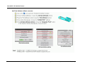
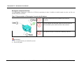
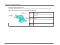
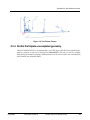
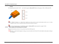
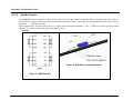
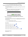
4.3.5.5
Data Bus Coupler
The Coupler Reference Designator is the interface name of the Data Bus coupler component. Data bus shilded group wires cable are
connected to the Coupler using named points with predefined formats on each Coupler side. The ampersand behaves like or between two
expression. "....." indicates wild cards.
In the example below, pin name with prefix 1 or 3 will be routed to the point with name "1...&3...". While wires whose pin name contain
the prefix 2 or 4 will be routed to the point with name "2…&4…".
Example
Figure 18: Data Bus Coupler Connections
Figure 17: SWD Data Bus
61
Document Version E
Printed Copy is for reference only
Proprietary
THarnesSYS™T - NX Interface User Manual
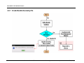
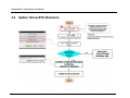
4.4
Export Bundle Geometry
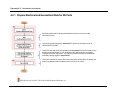
The User Function that is built inside NX module creates a file with the extension 3d asc at the specific predefined folder. The file
contains the bundle segments geometrical definitional the User Function adds attributes to the bundle model and checks the validation of
the NX geometry.
62
Document Version E
Printed Copy is for reference only
Proprietary
HarnesSYS - NX Interface Process
The following chart describes the work flow while transferring NX bundle model to HarnesSYS™.
63
Document Version E
Printed Copy is for reference only
Proprietary
THarnesSYS™T - NX Interface User Manual
List of Links
Check HarnesSYS Import & Export Folder Definitions................................................... 15
Create Bundle Geometry File ......................................................................................... 65
Define Bundle Name Parameter..................................................................................... 70
Set Parameters to Define Bundle Features.................................................................... 73
64
Document Version E
Printed Copy is for reference only
Proprietary
HarnesSYS - NX Interface Process
4.4.1 Create Bundle Geometry File
65
Document Version E
Printed Copy is for reference only
Proprietary
THarnesSYS™T - NX Interface User Manual
List of Links
Define Bundle Variables ................................................................................................. 67
NX Error Management Window...................................................................................... 72
66
Document Version E
Printed Copy is for reference only
Proprietary
HarnesSYS - NX Interface Process
4.4.2 Define Bundle Variables
67
Document Version E
Printed Copy is for reference only
Proprietary
THarnesSYS™T - NX Interface User Manual
68
Document Version E
Printed Copy is for reference only
Proprietary
HarnesSYS - NX Interface Process
69
Document Version E
Printed Copy is for reference only
Proprietary
THarnesSYS™T - NX Interface User Manual
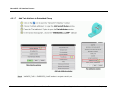
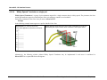
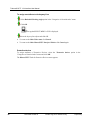
4.4.3 Define Bundle Name Parameter
When you start working with the HarnesSYS™ Interface, the bundle-dash number must be
assigned to the Bundle assembly part as Part attribute in order to recognize the Bundle within
the bundle assembly.
In order to assign the Bundle Name as a Part attribute of the Bundle assembly part, perform the
following:
The Bundle assembly part should be the Work Part
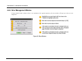
Select the first activity from the HarnesSYS™ Interface Main Window
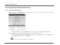
The following "Categories of Electrical Tasks" menu is displayed:
In the "Categories of Electrical Tasks" menu that appears choose the "Assign Bundle to
Part" Option and click OK.
70
Document Version E
Printed copy is for reference only
Proprietary
HarnesSYS - NX Interface Process
Figure 19: Categories of Electrical Tasks
The following pop-up menu appears
Type a value for the bundle name attribute with the format xxxx-yyy where :
xxxx is a bundle number
yyy
is a dash number
Example: 4002-501
Click OK to confirm attribute value.
To return to the Main HarnesSYS™ Interface Window choose Cancel.
Proprietary
Document Version E
Printed copy is for reference only
71
THarnesSYS™T - NX Interface User Manual
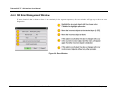
4.4.4 NX Error Management Window
If some electrical data is absent or there is no continuity in the segment sequences, the error window will pop up to show an error
diagnostics.
Figure 20: Error Window
72
Document Version E
Printed Copy is for reference only
Proprietary
HarnesSYS - NX Interface Process
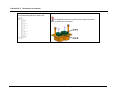
4.4.5 Set Parameters to Define Bundle Features
4.4.5.1
Add Task Attributes Option
Select the first activity from the HarnesSYS™ Interface Main Window. This activity sets the specific attributes of the NX model before
the Bundle Geometry file (*.3d_asc) is created.
There are two kinds of HarnesSYS™ Attributes:
1. Part attributes
- Assigned to an NX Work Part
2. Object attributes - Assigned to an NX Object
When Part attributes are assigned to the Bundle (the top-assembly part), it should be the Work and Displayed Part.
When Part attributes are assigned to a Bundle component, the component part should be the Work Part.
When Object attributes are assigned to an NX-Object (line, point etc.), the Bundle object should be the Display Part and
the owning Component should be set as the Work Part.
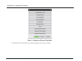
The following "Categories of Electrical Tasks" menu displayed:
73
Document Version E
Printed Copy is for reference only
Proprietary
THarnesSYS™T - NX Interface User Manual
Figure 21: Categories of Electrical Tasks Menu
The following List of Links enable you to jump to appropriate place in this user manual.
74
Document Version E
Printed Copy is for reference only
Proprietary
HarnesSYS - NX Interface Process
List of Links
1. Assign Bundle Number .................................................................................... 78
2. Designator Point Definition.............................................................................. 78
3. " Do not participate" Definition ......................................................................... 78
4. Segment Attributes........................................................................................... 79
5. Part Attributes .................................................................................................. 81
6. Protective devices ............................................................................................ 82
7. Notes................................................................................................................ 83
8. Grouping Widely Spaced Terminators ............................................................. 85
9. Backshell Clocking Angle................................................................................. 81
10. Bundle Shrinkable Sleeve ................................................................................ 85
75
Document Version E
Printed Copy is for reference only
Proprietary
THarnesSYS™T - NX Interface User Manual
Add task Attributes Option (Continue)
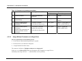
Table 13: Categories of Electrical Tasks
Category
Assign Bundle to Part
Description
Enables the user to assign the HARNESS_BUNDLE_NAME =bundle-dash Part attribute to
the top-assembly Work and Display part.
When starting work with the HarnesSYS™ Interface, the bundle-dash number must be
assigned to the top-assembly as a Part attribute in order to recognize the Bundle within the
bundle assembly.
Designator Point
The attribute with "DESIGNATOR_POINT" value should be assigned to the termination point
in the devices such as connector, WST etc.
The attribute with "DESIGNATOR_POINT" value may also be assigned to a point on the
routing object in the bundle, indicating a termination of the routing in the aircraft. See detail
(on page 57)
76
Do not Participate
Enables the user to assign a HARNESS_TASK that implies ignoring the selected component
or object. See detail
Segment attributes
Enables the user to assign attributes to a Routing Segment.
Part attributes
Enables the user to assign HARNESS_TASK attributes as Part attributes. This function is
used to define components in a part library. In order to use this function the user must set the
desired part to be the current Display Part. See detail (on page 26)
Protective devices
Enables the user to assign attributes to the protective devices.
Notes
Enables the user to assign notes such as Red Label, Clamp Marker etc. as Object attributes.
Widely spaced
terminator
This obsolete option Enables the user to assign the HARNESS_TASK =
WIDELY_SPACED_TERMINATOR attribute to NX group object. Widely Spaced Terminator
may be defined within a single part using Part attribute. Alternatively several lugs may define
Widely Spaced Terminator using naming convention to each individual lug.
Document Version E
Printed Copy is for reference only
Proprietary
HarnesSYS - NX Interface Process
Category
77
Description
Backshell Clocking
Angle
Enables the user to set the keyway direction of the backshell as a line attribute. See detail
Bundle Shrinkable
Sleeve
Enables the user to assign larger diameters in NX than they are in HarnesSYS™ (this may
occur appear when a bundle is sealed in a fuel tank)
Document Version E
Printed Copy is for reference only
Proprietary
THarnesSYS™T - NX Interface User Manual
Assign Bundle Number
A bundle number is set as a Part attribute in the NX Part. It indicates that the NX Part and its
Component Parts contain this bundle information.
Select "Assign Bundle to Part" Option in the "Categories of Electrical Tasks menu" and
click OK. The following pop-up menu appears
Figure 22: Cue: Enter HARNESS_BUNDLE_NAME value
Type a value for the bundle name attribute with format xxxx-yyy where :
xxxx is a bundle number
yyy
is a dash number
Example name attribute: 4002-501
Click OK to confirm attribute value.
To return to the Main HarnesSYS™ Interface Window click Cancel again.
Designator Point Definition
See usage details.
To assign a Designator Point attribute:
Select the "Designator Point" option in the "Categories of Electrical Tasks menu" and click
OK.
The regular SELECT MENU of NX is displayed.
Select a point and click OK .
To return to the Main Tasks menu choose Cancel.
To return to the Main HarnesSYS™ Interface Window choose Cancel again.
" Do not participate" Definition
See usage details.
78
Document Version E
Printed copy is for reference only
Proprietary
HarnesSYS - NX Interface Process
These object attributes may be removed using the regular NX tools.To assign a
"Do not participate" attribute perform the following:
Select the "Do not participate" option in the "Categories of Electrical Tasks menu" and click
OK .
The regular SELECT MENU of NX is displayed.
You may select a Component, Group of objects or a Routing object.
To return to the Main Tasks menu choose Cancel.
To return to the Main HarnesSYS™ Interface Window choose Cancel again
Segment Attributes
Segment attributes such as EMI or RUN letter will be shown on the HarnesSYS™ jig (form
board) Braid thickness will set additional segment thickness according to the segment diameters
in HarnesSYS™.
To assign attributes to Segment Curves:
Select the "Segment attributes" option in the "Categories of Electrical Tasks" menu.
Click OK.
The Harness Tasks for Segment Attributes menu appears.
Proprietary
Document Version E
Printed copy is for reference only
79
THarnesSYS™T - NX Interface User Manual
Figure 23: Cue: Enter 'HARNESS_CLAMP_MARKER' value
This category contains the assignment of different curve types.
Select one of the following options:
1. HARNESS_BRAID_THICKNESS.
2. HARNESS_EMI, HARNESS_EMI_GROUP_NAME & HARNESS_RUN_LETTERS.
HARNESS_BRAID_THICKNESS
To assign the sleeve to the appropriate Segment/Curve:
In the pop-up window, enter the sleeve thickness:
Figure 24: Cue: Enter HARNESS_BRAID_THICKNESS value
The regular SELECT MENU of NX is displayed.
Choose the segment to which to add the sleeve value to the segment diameter of the single
segment, or choose the bundle object to which to add the sleeve value to the diameter of all
segments in the bundle object.
80
To return to the Main Tasks menu click Cancel.
Document Version E
Printed copy is for reference only
Proprietary
HarnesSYS - NX Interface Process
To return to the Main HarnesSYS™ Interface Window click Cancel again.
HARNESS_EMI, HARNESS_EMI_GROUP_NAME & HARNESS_RUN_LETTERS
These are alternative attributes that may be set on segments. They add information about the EMI
level applicable to that segment.
To assign Run Letters, Harness EMI or Harness EMI Group Name to segments, select one of the
attributes:
HARNESS_EMI , HARNESS_EMI_GROUP_NAME , HARNESS_RUN_LETTERS
from the "Categories of Electrical Tasks" menu and click OK.
The following pop-up window appears (not for HARNESS_EMI):
Figure 25: Cue: Enter EMI_GROUP_NAME (HARNESS_RUN_LETTERS) value.
Enter the Name and press OK.
The regular SELECT MENU of NX is displayed. The User may select centerline objects such as
lines or Segment Curves, which represent segments with HARNESS_EMI , RUN LETTERS or
EMI GROUP NAME.
To return to the Main Tasks menu click Cancel.
To return to the Main HarnesSYS™ Interface Window click Cancel again.
Part Attributes
Add Task Attribute to Basic connector (on page 31)
Circular Connector Structure (on page 32)
Add Task Attribute to Data Bus Coupler (on page 35)
Add Task Attribute to Rectangular connector (on page 37)
Add Task Attribute to Widely spaced terminator on single part (on page 39)
Backshell Clocking Angle
See usage details.
Proprietary
Document Version E
Printed copy is for reference only
81
THarnesSYS™T - NX Interface User Manual
To assign an attribute to the keyway Line:
Select Backshell Clocking Angle option in the "Categories of electrical tasks" menu.
Click OK.
The regular SELECT MENU of NX is displayed.
Select the keyway line object and click OK.
To return to the Main Tasks menu click Cancel.
To return to the Main HarnesSYS™ Interface Window click Cancel again.
Protective devices
To assign attributes of Protective Devices, select the "Protective devices option in the
"Categories of electrical tasks" menu and click OK.
The HarnesSYS™ Tasks for Protective Devices menu appears.
82
Document Version E
Printed copy is for reference only
Proprietary
HarnesSYS - NX Interface Process
Figure 26: HarnesSYS™ Tasks for Protective Devices Menu
Select one of the different types of protective devices.
The regular SELECT MENU of NX is displayed.
The user may select Component or Group of objects. Each of them collects all the edge
points of each protective device on the segments.
To return to the Main Tasks menu click Cancel.
To return to the Main HarnesSYS™ Interface Window click Cancel again.
Notes
To assign a note attribute, select "Notes" option in the "Categories of electrical tasks" menu and
click OK.
The Harness Tasks for Notes menu appears:
Proprietary
Document Version E
Printed copy is for reference only
83
THarnesSYS™T - NX Interface User Manual
Figure 27: Harness Tasks for Notes Menu
Select one of the different types of notes.
To assign a Clamp marker Name to a point, select: CLAMP MARKER
The following pop-up window appears:
Figure 28: Cue: Enter 'HARNESS_CLAMP_MARKER' value
The regular SELECT MENU of NX is displayed.
The user may select a Point.
To assign any other note, select: CODE or FERRULE_LIMITS or IDENT or NOTE or
RED_LABEL
The regular SELECT MENU of NX is displayed.
The user may select a Point.
84
To return to the Main Tasks menu choose Cancel.
Document Version E
Printed copy is for reference only
Proprietary
HarnesSYS - NX Interface Process
To return to the Main HarnesSYS™ Interface Window choose Cancel again.
Grouping Widely Spaced Terminators
This obsolete option is used to set attribute to a grouping object for several connector that
indicates wire ends in each pin separately.
Lug is no longer defined as a WIDELY SPACED TERMINATOR object attribute.
See Route Paths for each Lug connected to the same Stud
Bundle Shrinkable Sleeve
To assign the same thickness to all segments in the bundle:
The attribute is added to the Display Part.
Select the "Bundle Shrinkable Sleeve" option.
In the interface window that appeares enter the Braid thickness.
Figure 29: Cue: Enter 'HARNESS_BUNDLE_BRAID_THICHNESS' value
Click OK.
Proprietary
Document Version E
Printed copy is for reference only
85
THarnesSYS™T - NX Interface User Manual
4.4.6 Error Management Window
If some electrical data is absent or there is no continuity in the segment sequences, the error window will pop up to show an error
diagnostics.
Figure 30: Error Window
86
Document Version E
Printed Copy is for reference only
Proprietary
4.5
Check Bundle Geometry against BTP & Receive
Diameters
This function compares WIre List and Part List data appearing in the BTP document with the
bundle geometry data of the 3D model in XML format.
In This Chapter:
HarnesSYS: Check Bundle Geometry against BTP........................................................88
The following scheme describes the HarnesSYS™ requirement prior to this activity.
List of Links
Check HarnesSYS Import & Export Folder Definitions ...................................................15
HarnesSYS: Check Bundle Geometry against BTP........................................................88
Proprietary
Document Version E
Printed copy is for reference only
87
THarnesSYS™T - NX Interface User Manual
4.5.1 HarnesSYS: Check Bundle Geometry against BTP
This function compares Wire List and Part List data appearing in the BTP document with the bundle geometry data of the 3D model, in
XML format.
Select the appropriate BTP document from the HarnesSYS™ workspace.
88
Document Version E
Printed Copy is for reference only
Proprietary
HarnesSYS - NX Interface Process
Press MB3 3D Vs BTP or choose the "3D vs. BTP" icon from the BTP toolbar.
89
Document Version E
Printed Copy is for reference only
Proprietary
THarnesSYS™T - NX Interface User Manual
The following menu appears:
It contains the 3d_asc files that appear in the HarnesSYS™ import folder and have the same BASE NUMBER as the BTP base number.
Select the desired file and click OK.
90
Document Version E
Printed Copy is for reference only
Proprietary
HarnesSYS - NX Interface Process
The check process is run in another window. The check process is similar to the Integrate BTP process described in "Integrate BTP" user
manual.
The following log file shows a typical result. The notes indicate that this check process indents to NX users in order to check their data
against the HarnesSYS™ model.
91
Base-dash number value was assigned as an attribute to the Bundle using the HarnesSYS™ - NX interface.
Document Version E
Printed Copy is for reference only
Proprietary
THarnesSYS™T - NX Interface User Manual
92
Document Version E
Printed Copy is for reference only
Proprietary
HarnesSYS - NX Interface Process
93
Document Version E
Printed Copy is for reference only
Proprietary
THarnesSYS™T - NX Interface User Manual
4.6
94
Update HarnesSYS Diameters
Document Version E
Printed Copy is for reference only
Proprietary
HarnesSYS - NX Interface Process
4.6.1 Display or Modify NX Stock Diameter
95
Document Version E
Printed Copy is for reference only
Proprietary
THarnesSYS™T - NX Interface User Manual
4.7
Apply the Bundle Changes
It is good practice to consult Electrical Designers before extensive changes are applied, because the bundle is designed by different
disciplines. Sometimes changes in HarnesSYS™ may provide a better solution.
96
Document Version E
Printed Copy is for reference only
Proprietary
HarnesSYS - NX Interface Process
97
Document Version E
Printed Copy is for reference only
Proprietary
THarnesSYS™T - NX Interface User Manual
4.8
Integrate BTP to Create Jig
Figure 31: Integrate BTP to Create Jig Scheme
*** BTP processes are defined in detail in the HarnesSYS™ Integrate BTP User Manual. The
Integrate BTP process includes functionalities such as:
98
Build Jig
Build Not-to-Scale 2D Drawing
Update Existing Jig
Update Wires Lengths
Document Version E
Printed copy is for reference only
Proprietary
4.9
Confirm BTP and Release
*** This process is defined in detail in the HarnesSYS™ Integrate BTP User Manual.
Home
Introduction....................................................................................................................... 1
Proprietary
Document Version E
Printed copy is for reference only
99
Glossary of Terms
Glossary of Terms
A
Abbreviation Class
Defines the class of part (for example P for plug, SW for switch, etc)
Access Door
Access point (flap, door or other entrance) in aircraft used to install or access the part or bundle.
Area Code
The area code indicates the physical location of the part in the production unit.
Authority
Documents that authorize changes. They are located in the Authority Library
B
Backfield
Protection for connector which provides grounding or mechanical support
Box Interface
Boxes are independent electrical units, often connected to bundles by specific interface.
Braid Stop
The distance between the BRD and the end of the braid (see
Project Defaults, Manufacturing).
Branch segment (branch)
Is a geometric JIG element containing wires. The branch is identified by uniformity of its wires.
BRD
Basic Reference Designator, also referred to simply as a
Designator, the connector’s local name.
BTP (Build-To-Package)
Document describing the packaging to produce a bundle. Generally it is a collection of WL/PL
and JIG DATA. Must contain at least WL or PL.
Proprietary
Document Version E
Printed copy is for reference only
101
Glossary of Terms
Bundle
Each wire must belong to a bundle. A bundle name is composed of a bundle (base) number and
dash number. The number of the bundle to which the wire belongs is often entered before the
wire name on the SWD.
C
CAD
Computer Aided Design
Contact Key
Code determining number and names of pins, defined in Contact Configuration Library. A part
number has a unique contact key.
Contact Type
Type of contact: 4 options – Pin, Stud, Socket, Solder
D
Dash Number
A descriptor of a document or bundle which associates the document with effectivity.
Designator
Each occurrence of a part in a SWD has a "code name" e.g. YP100. This is the (base) designator
of the part. This number is unique in the Product.
Device Type
Type of device installed in bundle. In HarnesSYS™ there are 15 options.
Diameter
The diameter of the segment which is calculated using a fixed formula which takes into account
the various types of wires that pass through the segment.
Document
Configuration controlled document of a specific type such as SWD/WL/PL/BTP.
E
Effectivity
The effectivity of an item is the set of production units (i.e. the subset of all the production units
being manufactured) to which that item applies.
The following documents have effectivities: part list (with dash number), wire list (with dash
number), SWD (with dash number).
102
Document Version E
Printed copy is for reference only
Proprietary
Glossary of Terms
The following items also have effectivities: wire, part occurrence, bundle (with dash number). In
effect the effectivity of a bundle (with dash number) is the same as the effectivity of its wire list
(with dash number).
EGN
An attribute assigned to segments to enable separation of wires with different EMI attributes.
EMI
Electromagnetic interference. The code value representing the susceptibility to interference with
the signals that a wire carries when these signals are disrupted by electromagnetic emission from
adjoining current carrying wires.
F
Family
Family code ferrule connecting several shields, name fields in wire record, Find Base Number
Part List W/L Dash flt file FROM_WIRE_INTEGRATE.
I
Integrate BTP
When the project default parameter Multi Path allowed is not checked, an error is displayed if
the integrated source contains Multi Paths.
Integrating a Wire
Integration of part integration process data flow logic flow intersecting effectivity issue.
J
Jig
A full scale 1:1 layout for the construction of a wire bundle. Also called Form-board.
Jumper
Name number translation of a short default wire.
L
LCD
last Change Date. Date document last changed.
M
Mating Connector
The matching Connector assigned to a connector via the Part Occurrence mating field.
Proprietary
Document Version E
Printed copy is for reference only
103
Glossary of Terms
Multi Path
A path or a part of a path, which includes more then one alternative configuration for routing
wires.
N
Null Path
The default path, if there is no correlation between segments and wires. If there are several
alternative routing options at a node and there is not enough information to define the path, the
null path should be the longest one.
P
Parts List (PL)
List of parts contain in a specific version of a bundle.
Path
Is a collection of continuous branch segments for routing wires. There may be single path or
several parallel paths between two designators.
Plug
A device which by insertion to a receptacle establishes contact.
Plug Program Number (PPN)
The PPN (Plug Program Number) of a part is a key determining the order in which wires should
be attached to the pins of the part. The key has 3 fields: major, sub and degree.
Private File
A file, generally a report, that is produced by a HarnesSYS™ transaction, stored in user’s private
directory and only available to the user initiating the process.
Production Unit
The unit being designed or manufactured e.g. an aircraft.
Protective Device
A lamination protecting the bundle wires, such as; boot, sleeving, conduit or spiral-wrap.
R
Receptacle
A contact device connected to a power supply and equipped to receive a plug.
Retrofit Installation Drawings- RID
Drawings showing only the change.
104
Document Version E
Printed copy is for reference only
Proprietary
Glossary of Terms
Retrofit Master Document RMD
Folder that contains all the documents required to implement the retrofit
Revision Letter
Letter determining the issue of a document. Every time a document is opened in order to modify
it, its revision letter is raised. It can have the values NEW or A, B, C etc.
In addition the revision letter may include point release data. Point release is sequential number
indicating inner release of the bundle. The document may be released in the following order:
00.01 00.02
Point releases
NEW
Firm release
NEW.01 NEW.02
A
Point releases
Firm releases
A.01
A.02... etc
Routing
The path taken by a wire from one part to another.
S
Same Wire
In 2 (SWD) System Wiring Diagram sequence number shield levels name significant wire name
spare pin special designators splice named translation of unnamed spt file starting/ending point
status suffix SWD symbol bank System wiring Diagram.
Segment (Branch)
A section of a bundle that lies between two nodes or between a part and a node or between two
parts. Also referred to as a branch.
Segment Length
The length of a segment or branch, stated in millimeters or inches as defined in the Project
Defaults. This length can be between two nodes or between a part and a node or between two
parts.
Service Code
Type of retrofit change: A (Add), D (Delete), C (Change), B (Before).
Shell Code
Shell codes contain information about connector back shells (or rear side of the connector). The
three variables concerning shell codes are the size, whether the connector is a receptacle or a
plug, and whether it is straight or angled. Thus each shell size can have four shell codes.
Shrink Ratio
The nominal ratio of expanded diameter to recovered diameter of heat shrinkable tubing
Signal Type
Type of signal at interface box connection – 13 options:
Proprietary
Document Version E
Printed copy is for reference only
105
Glossary of Terms
Communication, GND Analog, GND Digital, GND Chassis, GND Power DC, GND Power AC,
Lighting, MUX-BUS, Power AC, Power DC, RF, Signal Analog, Signal Digital
Sleeve Size
Diameter of sleeve around wire
Spare Pin
Is a designator pin, left unused (unattached to a wire). The pin requires special treatment such as
capping.
Stick Diagram
Initial Jig diagram where all the lines are straight, the lengths of the branches are drawn to scale,
and the dimension lines are removed.
System Wiring Diagram (SWD)
Old names: Schematic Diagram or Wire Diagram or Wiring Diagram.
A document which presents the design of a logical system e.g. air conditioning, landing system.
A SWD has a base number indicating the logical system which it describes, and a dash number
indicating its effectivity.
T
Termination Code
Code indicating possible terminations at that point
U
Update
Update wire process.
V
Vendor
Approved supplier of materials and parts whose details appear in Vendor library.
W
W/L
List of wires contained in a specific version of a bundle.
Wire Accommodation
The Wire Accommodation indicates the range of wires that a terminator can accommodate
Wire Length
The length of a wire connecting one part to another (including the route through a number of
segments and branches).
106
Document Version E
Printed copy is for reference only
Proprietary
Glossary of Terms
Wire List (WL)
List of wires contained in a specific version of a bundle.
Wire Type
A 3-element code for describing type of wire; consists of family type, specification type and
gauge, which are obtained from the bundle wire list data.
Work Package
Includes a group of instructions for maintenance and repair of the wire, or a list of tools needed
for the task and a cross reference table for it
Work Package Set
Group of work packages for a system or sub-system
Proprietary
Document Version E
Printed copy is for reference only
107
Index
A
C
Abbreviation Class • 101
About this User Manual • x
Access Door • 101
Adapter Structure • 28, 46
Add Task Attribute to Adapter • 47
Add Task Attribute to Basic connector • 31, 81
Add Task Attribute to Circular Angled Backshell
• 43
Add Task Attribute to Circular Connector • 33
Add Task Attribute to Data Bus Coupler • 35, 81
Add Task Attribute to Embedded Clamp • 49
Add Task Attribute to Rectangular angled
backshell • 45
Add Task Attribute to Rectangular connector • 37,
81
Add Task Attribute to Straight Backshell • 41
Add Task Attribute to Widely spaced terminator
on single part • 39, 81
Add Task Attributes Option • 73
Add task Attributes Option (Continue) • 76
Aim and Sub-aims of the HarnesSYS - NX
Interface Process. • 1
Apply the Bundle Changes • 96
Area Code • 101
Assign Bundle Number • 78
Assign Multiple Terminators at a Single Point •
51, 56
Audience • x
Authority • 101
CAD • 102
Check Bundle Geometry against BTP & Receive
Diameters • 87
Check HarnesSYS Import & Export Folder
Definitions • 15
Check the Installation of HarnesSYS - NX
Interface • 13
Circular Angled Backshell Structure • 28, 42
Circular Connector Structure • 28, 32, 81
Confirm BTP and Release • 99
Connectors • 29
Contact Key • 102
Contact Type • 102
Conventions • ix
Copy Files • 5
Coupler part Structure • 28, 34
Create Branch Segment • 51, 52
Create Bundle Geometry File • 65
B
Backfield • 101
Backshell Clocking Angle • 81
Backshells • 40
Basic connector structure • 28, 30
Basics • 27
Box Interface • 101
Braid Stop • 101
Branch segment (branch) • 101
BRD • 101
BTP (Build-To-Package) • 101
Bundle • 102
Bundle Shrinkable Sleeve • 85
108
Document Version E
D
Dash Number • 102
Data Bus Coupler • 51, 61
Define Bundle Name Parameter • 70
Define Bundle Variables • 67
Design Flexible Segments for 2D Manufacturing •
51, 52
Designator • 102
Designator Point Definition • 58, 78
Device Type • 102
Diameter • 102
Display or Modify NX Stock Diameter • 95
Do Not Participate uncompleted geometry • 53
Document • 102
Document Organization • xi
Document Revisions History • vii
E
Effectivity • 102
EGN • 103
Embedded Clamp Structure • 28, 48
EMI • 103
Error Management Window • 86
Export Bundle Geometry • 62
Export HarnesSYS Parts • 21
Printed copy is for reference only
Proprietary
Export Parts List • 21
F
Family • 103
G
Grouping Widely Spaced Terminators • 85
H
HARNESS_BRAID_THICKNESS • 80
HARNESS_EMI,
HARNESS_EMI_GROUP_NAME &
HARNESS_RUN_LETTERS • 81
HarnesSYS
Check Bundle Geometry against BTP • 88
HarnesSYS - NX Interface Process • 19
I
Install HarnesSYS Interface Icon • 8
Installation of HarnesSYS - NX Interface • 2, 5,
13
Integrate BTP • 103
Integrate BTP to Create Jig • 98
Integrating a Wire • 103
Introduction • 1
J
Jig • 103
Jumper • 103
L
LCD • 103
M
Mating Connector • 103
Multi Path • 104
N
Notes • 83
Null Path • 104
NX Error Management Window • 72
NX Implementation of Bundle Structure • 18
P
Part Attributes • 81
Parts List (PL) • 104
Path • 104
Place HarnesSYS Parts in Model • 25, 51
Plug • 104
Proprietary
Document Version E
Plug Program Number (PPN) • 104
Preface • ix
Prepare Electrical and Geometrical Data for NX
Parts • 18, 26, 76
Private File • 104
Production Unit • 104
Protective Device • 104
Protective devices • 82
R
Receptacle • 104
Rectangular angled backshell Structure • 28, 44
Rectangular Connector Structure • 28, 36
Related Documents • x
Retrofit Installation Drawings- RID • 104
Retrofit Master Document RMD • 105
Revision Letter • 105
Route Paths for each Lug individually • 54
Route the Geometrical Bundle • 51
Route the Main Path • 51
Routing • 105
S
Same Wire • 105
Segment (Branch) • 105
Segment Attributes • 79
Segment Length • 105
Service Code • 105
Set environmental variables • 6, 16
Set Parameters to Define Bundle Features • 73
Shell Code • 105
Shrink Ratio • 105
Signal Type • 105
Sleeve Size • 106
Spare Pin • 106
Special End Connector Cases • 54
Stick Diagram • 106
Straight Backshell Structure • 28, 40
System Wiring Diagram (SWD) • 106
T
Termination Code • 106
Terminology • 2
U
Update • 106
Update HarnesSYS Diameters • 94
Use named points indicating wire end path • 51,
57, 76
Printed copy is for reference only
109
V
Vendor • 106
W
W/L • 106
Widely Spaced Terminator on single part • 51, 59
Widely spaced terminators on single part
Structure • 28, 38
Wire Accommodation • 106
Wire Length • 106
Wire List (WL) • 107
Wire Type • 107
Work Package • 107
Work Package Set • 107
110
Document Version E
Printed copy is for reference only
Proprietary