1
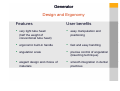
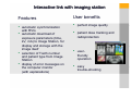
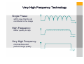
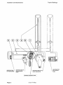
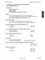
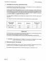
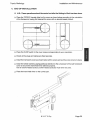
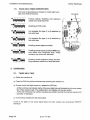
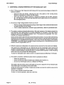
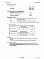
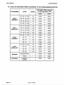
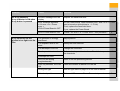
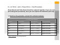
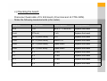
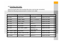
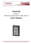
ELITYS
-kodak
ELITYS-kodak
2000
Very High Frequency Intra-Oral X-ray unit
A top of the line X-ray unit matching
the new challenges of dentistry:
•
Radioprotection and safety
of both patients and staff
•
Reliability and quality guaranteed
by the most stringent medical
standards
•
Ease of use and user-friendly
•
Perfect image quality - every time
Generator
Very high frequency technology
Generator
Very high frequency technology
Features
User benefits
•
very High Frequency: 300 kHz
• elimination of soft X-rays
• more penetrating X-rays
• shorter exposure times,
with a precision down to
the millisecond
•
•
•
patient dose reduction of 30%
longevity of the X-ray tube
less motion blurring
•
0.7 mm² focal spot (IEC)
sharp images
•
optional rectangular collimator
•
•
X-ray protection and safety
Generator
Very high frequency technology
Features
User benefits
•
choice of intensity:
• 7 mA for film
• 4 mA for RVG
•
first X-ray unit specifically
designed for direct digital
radiography (dose reduction)
•
choice of power:
• 60 kV for more contrast
• 70 kV for more grey levels
•
selection of power according
to exam type:
• 60 kV for endodontics,
caries detection, etc.
• 70 kV for periodontics
RVG is a Dr. Mouyen licence
Generator
Design and Ergonomy
Features
User benefits
•
very light tube head
(half the weight of
conventional tube head)
•
easy manipulation and
positioning
•
ergonomic built-in handle
•
fast and easy handling
•
angulation scale
•
precise control of angulation
(bisecting technique)
•
elegant design and choice of
materials
•
smooth integration in dental
practices
Scissor arm
Technology and design
Features
•
unique oil/air cylinder design
(Trophy patent)
•
choice of 3 arm lengths:
1,70 - 1,88 - 2,05 m
67 - 74 - 81 "
User benefits
•
•
•
smooth and precise movement
low inertia
stable positioning
•
adapts to every practice
configuration
Wall bracket
Design and Flexibility
Features
User benefits
•
magnetic attachment of
handheld timer to bracket
•
easy handling of timer
•
3 mounting possibilities:
• horizontal arm to the right
• horizontal arm to the left
• vertical
•
adapts to every practice
configuration
•
optional pass-through bracket
Timer
Technology and Design
Timer
Technology and High Precision
Features
User benefits
•
Microprocessor control
•
precision and reproducibility
of the exposure parameters
(down to the millisecond)
•
LCD screen display of
exposure parameters:
• power (kV)
• intensity (mA)
• exposure time (ms)
•
•
ease of use
errors belong to the past
Timer
Design and Ergonomy
Features
User benefits
•
•
easy handling and mobility
•
•
•
straightforward use
optimised exposure times
each film is perfectly exposed
and radiation kept to a minimum
•
•
extreme miniaturization:
all functions are regrouped
in a hand-held timer
operation through
a dental arch and
self-explanatory icons
optional remote
timer kit
•
•
adapts to every practice
configuration
Interactive link with imaging station
Interactive link with imaging station
Features
User benefits
•
•
perfect image quality
•
patient dose tracking and
radioprotection
•
userfriendly
operation
•
easy
trouble-shooting
•
•
•
automatic synchronization
with RVG
automatic download of
exposure parameters (time,
kV, mA) to Image Station, for
display and storage with the
image itself
selection of Tooth number
and patient type from Image
Station
display of error messages on
the computer monitor
(with explanations)
Very High Frequency
The Very High Frequency
technology of ELITYS sets
a new standard in dental
intra-oral radiography, in
terms of performance,
image quality, and
radioprotection
Very High Frequency Technology
Single Phase:
soft X-rays that do not
contribute to the image
High Frequency:
better quality X-rays
Very High Frequency:
minimal dose and
perfect image quality
kodak2000
kodak2000
Technical Training
- Test and Reset List -
Elitys_maintlevel_ v0703
Meaning of alarm list
Available for Eprom version 9.04
•
« Cooling » cooling cycle, wait until the message disappeares
•
« kV Error »: this message means that the kV value is less than
50 kV during more than 10 ms
•
« Power Error » Vh>
230 V
115 V
> 320 VAC
< 47 VAC
> 160 VAC
< 23 VAC
Ufilament<minimum voltage (ex. 2V)
Ifilament=0A or Filament Circuit HS
Initialisation or autotest procedure
•
To test the eprom:
Press the film type minus (f-). The message « Eeprom test » will be displayed,
during 30 seconds and after « Eeprom passed » will be displayed if the eeprom is OK.
•
Auto test:
Press RVG button and simultaneously switch the timer ON. You will see first the eeprom
version (Trophy V. 9.4), then it will test the leds, the key test by pushingany key, the
position of the switches (SW1-8…) and, finally, it will display the total number of
exposures.
•
Timer Reset:
Press the keys kV and RVG and simultaneously turn the timer ON.
The message « Elitys Init » will be displayed, this initialisation will reset the Thermal and
The exposure counter counter.
NOTICE:
To do this reset, you have to check the temperature of the tube head or ask the doctor
to wait minimum half an hour unusing the timer.
- Electronic Test Procedure -
TROUBLE SHOOTING
1/ Trouble-shoot procedures
Problem
Cause
Solution
Nothing lights up
ON/OFF green switch stays
OFF
Machine disconnected
Connect the machine (plug power supply)
Main circuit-breaker OFF
Put in ON
ON/OFF green switch is
defective or Power
connection problem
Check the 220V over the ON/OFF switch or remove the switch
and connect the line directly to terminals 7 and 8
Fuse problem
Check F4, F3, F2 and F1
LD3 is OFF on power board
CJ426
Replace Power Board
5V is not present on handheld timer
Replace hand held timer (including cable between timer and
Power Board). In case of 11 pin timer connector, leave the pin
on the TP2 side free.
The generator is cooling
Wait until the « Cooling » message disappeares (please refer to
User Manual)
X-ray button doesn’t work
Follow the auto test procedure – § 2 – to check hand-held Xray button. If it is defective, replace the hand-held timer
X-ray button is working
Replace the hand-held timer
Remote X-ray button
doesn’t work
Refer to the Installation Manual to set the dipswitches of the
hand-held timer correctly.
Nothing lights up on the
Hand-held timer but ON/OFF
green switch stays ON
No X-ray emission
(unexposed picture)
X-ray indicator remains OFF
when X-ray button is
pressed
Problem
Cause
Solution
No X-ray emission
X-ray indicator is ON when
X-ray button is pressed
No error message over the
display
Replace the hand-held timer
Error message appeares
« kV error » or « Power
error »
LD8 of Power Board is OFF
On the Power board, check between pins 3 and 4 of IC 13 if the
opto is turned on (should rise to ~ 1.2 Vdc)
If not, replace the hand held timer.
If yes, replace the Power Board
LD8 of Power Board is ON
Follow « kV Error » or « Power Error » test procedure – § 3.
The generator is wrongly
positioned
Adjust position
The exposure time is too
short
Modify the time selection
The developer is too old
Change the chemicals
Development time too short
Refer to development instructions. Check the temperatures of
the chemicals
X-ray emission OK but
picture is too light over the
film
Developer too cold
Film is in the wrong
way(backwards)
Refer to the film positioning section
RVG key selected, RVG led
ON
Press RVG button to switch OFF the led
Wrong film type
See film type table on page 18 of the User’s Manual
Tube head problem
Follow « kV Error » or « Power Error » test procedure – § 3.
Problem
Cause
Solution
Picture is too dark over
the film
Wrong film type
See film type table on page 18 of the User’s Manual
Exposure time too long
Modify the time selection
X-ray film pre-exposed
Change film box
Development problem
Refer to development instructions (development time,
temperature)
The exposure switch was
released before the end of the
exposure (X-ray button must be
pressed beyond the exposure
time)
Select a tooth to stop the alarm. The display shows the
remaining exposure time. Decide wether to develop or to
make another exposure.
Tube head, power board or
power arm cable problem
Stop the machine and then restart it
OP. Error
kV Error
Power Error
If the problemns remains, replace the hand-held timer.
If the problem remains, follow « kV Error » or « Power
Error» test procedure – § 3.
Problem
Cause
Solution
All the leds and beeper
are ON on the handheld timer
Eeeprom is out of the socket
Open hand-held timer and reinstall Eeprom
LCD of hand-held timer
is OFF but everything
remains normal
LCD brightness adjustment
Open hand-held timer and adjust brightness with P1 (solder side of keyboard)
2/ Auto test procedure
This procedure should be used to check the hand-held timer.
Select « Auto-test by pressing « RVG » button and simultaneously switch the timer ON.
Elitys software version will be displayed first, then « led test » will start and after, « key
test » will be displayed. Then, you can test hand-held timer buttons, if you don’t press any
button during 1 minute the timer will display the timer dipswitch configuration (SW 1–8: ----------), and after the exposure counter.
Then the timer is setted automatically to user mode.
3/ « kV Error » and « Power Error » Test Procedure
Power Board and Tube Head should be replaced together. If you are sure
(according test procedure), then you can replace the defective part only.
a) Switch on the generator, connect DC voltmeter between:
CJ 426 Power Board
Test point
And test point
Values required
If wrong measures
GND
+ 36 V
30 V < … < 41 V
Replace the board
GND
+ 12 V (LD 2)
11.4 V < … < 12.6 V
Replace the board
GND
+ 5 V (LD 3)
5.3 V < … < 5.9 V
Replace the board
0V
+ 15 V (LD 1)
13.5 V < … < 15 V*
Replace the board
0V
+ 5 VIN
4.8 V < … < 5.4 V*
Replace the board
* With CJ 426.V8: only during exposure
b) Power circuit check:
Switch off the generator. With multimeter, make the following measurements on CJ 426
board (ohm meter)
Between test point
And test point
Values required
If wrong measures
0 kV
+ kV
10.6 < … < 12.6 kΩ
Go to chapter c, d and e
0 mA
RTN mA
1 kΩ
Go to chapter c, d and e
0 mA
J2 – 8 (PWR ARM)
About 0 Ω
Go to chapter c, d and e
0 mA
J2 – 7 (PWR ARM)
About 0 Ω
Go to chapter c, d and e
0 mA
J2 – 6 (PWR ARM)
About 0 Ω
Go to chapter c, d and e
0 mA
J2 - 3 (PWR ARM)
Open circuit
Go to chapter c, d and e
0 mA
J6 – 1 (CTRL ARM)
About 3 kΩ
Go to chapter c, d and e
J2 – 1 (PWR ARM)
J2 – 3 (PWR ARM)
About 0 Ω
Go to chapter c, d and e
c) Checking the board:
Disconnect head-cable of CJ 426 board (J2 terminal and J6 CTRL ARM).
Make the following measurements (ohm meter).
Test point
And test point
Values required
If wrong measures
0 kV
+ kV
86.5 < … < 95.5 kΩ
Replace the board
0 mA
RTN mA
1 kΩ
Replace the board
0 mA
J2 – 8 (PWR ARM)
0Ω
Replace the board
0 mA
J2 – 6 (PWR ARM)
About 0 Ω
Replace the board
0 mA
J2 – 3 (PWR ARM)
Open circuit
Replace the board
0 mA
J6 - 1 (PWR ARM)
Open circuit
Replace the board
0V
G1
10 kΩ
Replace the board
0V
G2
10 kΩ
Replace the board
Tr 1
G4
10 kΩ
Replace the board
Tr 2
G5
10 kΩ
Replace the board
d) Checking tube head:
Keep the head-cable disconnected (the tube must remain connected)
Make the following measurements on scissor arm cable.
Size / wire color
Size / wire color
Values required
If wrong measures
Big / Blue
Small / Red
Open circuit
Replace the head
Big / Blue
Small / Yellow
12 < … < 14.6 kΩ
Replace the head
Big / Blue
Small / Green
3 kΩ
Replace the head
Big / Blue
Big / Purple
About 0 Ω
Replace the head
Big / Blue
Big / Brown
Open circuit
Replace the head
Big / Blue
Big / Yellow – green
About 0 Ω
(since 09/1996)
Replace the head
Big / Yellow – green
Big / Brown
Open circuit
Replace the head
Big / Yellow – green
(shield) / Black or white
About 0 Ω
Replace the head
Big / Brown
Big / Orange
About 0 Ω
Replace the head
e) Checking Power Arm cable:
Check power arm cable continuity, the cable between tube head and Power board CJ
426. Using an Ohmmeter, measure continuity of each wire.
If you find broken wires, replace the cable assembly (refer to the Installation Manual).
d) « Power Error » last test:
« V HEAT » led should light during pre-heat. If not, replace the board.
Check filament heating voltage (between test points « GND » and « V HEAT »), you
should measure 3 or 4 Volts DC. If not, replace the board.
g) Final check:
Program occlusal mode:
• Choose film type 9, 60 kV, 4 mA
Make an exposure and measure voltage between test point 0 mA and RTN MA (= mA)
You should measure between 3.4 V and 4.6 V (4 V).
• Choose film type 9, 60 kV, 7 mA
Make an exposure and measure voltage between test point 0 mA and RTN MA (= mA)
You should measure between 6.0 V and 8.0 V (7 V).
• Choose film type 9, 70 kV, 4 mA
Make an exposure and measure voltage between test point 0 mA and RTN MA (= mA)
You should measure between 3.4 V and 4.6 V (4 V).
• Choose film type 9, 70 kV, 7 mA
Make an exposure and measure voltage between test point 0 mA and RTN MA (= mA)
You should measure between 6.0 V and 8.0 V (7 V).
If your problem is not solved and if all these points are correct, replace power board and
hand-held timer (this is particularly relevant with the ceiling mount)