1
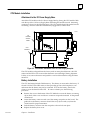
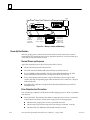
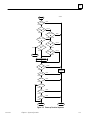
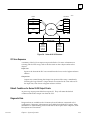
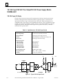
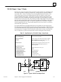
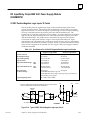
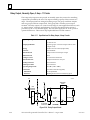
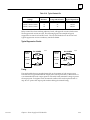
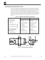
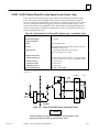
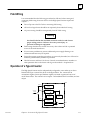
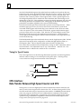
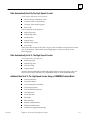
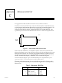
6
H
H
Count input which increments or decrements a 16 bit accumulator.
Preload/Strobe input which either preloads a user defined value into the
accumulator or strobes the accumulator into a register. In addition, the counter has
one dc output (Q1), with programmable on and off output presets.
Additional High Speed Counter Features
H
H
H
H
H
Two DC inputs with input voltage range of 12 to 30 VDC;
One DC output;
Counts per timebase register;
Software configuration;
Individual LEDs that provide a visual indication of Count input, preload/strobe
input and output status.
One input is used as a count signal. The other input is used as a strobe or preload inputs
depending on user configuration. The dc output can be used to drive indicating lights,
solenoids, relays, and other devices.
Power sources for input and output points must be supplied by the user or by the +24
VDC Isolated output on the Series 90-20 I/O power supply base module.
A Counts per Timebase register indicates the number of counts in a given time interval.
The Counts per Timebase data is a 16-bit signed number. The sign indicates up counts
(+) or down counts (–). The Timebase value is specified in milliseconds and ranges
from 10 to 65535 milliseconds (increments of 10 milliseconds).
All configuration parameters are stored in non-volatile memory in the PLC. An initial
(default) set of configuration parameters is used in the absence of user changes to
configuration.
Basic Features
Direct processing: The module is able to sense inputs, count and directly control one
output without the need to communicate with a CPU.
Selectable counter operation: Counter operation may be configured to count either up
or down.
Continuous or single-shot counting: The counter can be configured to operate in
either continuous or single-shot mode:
Continuous Counter Mode: If either the upper or lower count limit is
exceeded, the counter wraps around to the other limit and continues.
Single-Shot Counter Mode: The counter counts to either limit and stops.
When the counter is at the limit, counts in the opposite direction back it off
the limit. The Accumulator can also be changed by loading a new value
from the CPU or by applying a Preset Input.
Access to Accumulator: An internal memory location stores the accumulated count.
The CPU can read the value in the accumulator, or set it from the
application program. The accumulator value, which may be either positive
or negative, is represented as a two’s complement number.
Accumulator adjust: The Accumulator may be adjusted. The adjustment is an 8-bit
signed two’s complement offset value that is sent from the CPU whenever
an adjustment is required.
6-2
Series 90-20 Programmable Controller User‘s Manual – August 1995
GFK-0551C