1
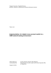
Electricwinches for towing and lifting Instruction manual Spare parts EC Declaration of Conformity WWL 125-50 000 kg E, EN, EK, EW H, HN P, PN TABLE OF CONTENT INFORMATION TO THE USER MANUAL............................................................................................................. 1 1. SAFETY INSTRUCTIONS FOR WINCHES ..................................................................................................... 3 1.1 Regulations ............................................................................................................................................ 4 2. INTRODUCTION........................................................................................................................................ 5 2.1 General .................................................................................................................................................. 5 2.2 Specification .......................................................................................................................................... 5 2.3 Main components of winches ............................................................................................................... 5 2.4 Description of the electric circuit .......................................................................................................... 6 2.4.1 Emergency stops ............................................................................................................................... 6 2.4.2 Characteristics with 230 V alternating current motors ..................................................................... 6 3. INSTALLATION ......................................................................................................................................... 7 3.1 Installation of the winch ........................................................................................................................ 7 3.1.1 Handling of the winch ....................................................................................................................... 7 3.1.2 Electric Motor Connection ................................................................................................................ 8 3.1.3 Electric motor brake connections ..................................................................................................... 9 3.2 Gearbox Lubrication ............................................................................................................................ 10 3.2 Gearbox Lubrication ............................................................................................................................ 10 3.3 Wire rope ............................................................................................................................................. 10 3.3.1 Angle of deflection of rope ............................................................................................................. 10 3.3.2 Fitting the wire rope to the winch drum ......................................................................................... 11 3.3.3 Handling and installation of the wire rope ...................................................................................... 12 3.4 Start up sequence ................................................................................................................................ 15 4. NOTES FOR A SECURE OPERATION ......................................................................................................... 16 4.1 Important notes for operation ............................................................................................................ 16 4.2 Possibilities of Control ......................................................................................................................... 18 5. CIRCULAR TESTING ................................................................................................................................. 19 5.1 Safety precautions during maintenance and repair ............................................................................ 19 5.2 Inspections ........................................................................................................................................... 19 5.3 Trouble Shooting ................................................................................................................................. 22 6. MAINTENANCE ...................................................................................................................................... 23 6.1 Lubrication ........................................................................................................................................... 23 6.2 Gearbox oil checks and changes .......................................................................................................... 24 6.3 Bolt tightening check ........................................................................................................................... 24 6.4 Adjustment of air gap of brake ............................................................................................................ 25 7. DISMOUNTING & RECYCLING ................................................................................................................. 25 APPENDIX 8. SPECIFIC WINCH INFORMATION 8.1 Technical data 8.2 Options / Additional equipment 9. SPARE PARTS 9.1 General layout drawing & parts list 10. CONTACT & CERTIFICATES 10.1 Contact address 10.2 EC Declaration of Conformity / EC Installation Declaration 11. Testcertificates 11.1 Yearly testing 11.2 Testcertificate User Manual TEKNOWINCH Rope Winches Page 1 INFORMATION TO THE USER MANUAL PURPOSE OT THE MANUAL This manual has been compiled by the Manufacturer to provide information on the safe transport, handling, installation, maintenance and repair of winches. Failure to adhere to the information provided herein may result in risk to personal health and safety, and may incur economic damages. The documentation must be stored by a person with the correct authority and must always be made available for consultation. A copy of the user manual can best be kept close the working area of the winch. The manual reflects the state of the art at the time of commercialization of the winch. The manufacturer reserves the right to modify, supplement and improve the manual, without the present publication being for that reason considered inadequate. Particularly significant sections of the manual and important specifications are highlighted by symbols whose meanings are given below. DANGER - WARNING This symbol indicates situations of serious danger which, if ignored, may result in serious risks to the health and safety of personnel. CAUTION - ATTENTION This symbol indicates the need to adopt specific precautions to avoid risks to the health and safety of personnel and possible economic damages. IMPORTANT This symbol indicates import and technical information. ATEX -WINCH In case that the winch is built according to the "ATEX“-directive 94/9/CE, you also have to consider the information given in the appendix "EX-PROOF-APPENDIX TEKNOWINCHROPE-WINCHES" beside the information given to you by this manual. Whether your winch is built according to this directive you can see on the EX-symbol printed on the type plate of the winch. User Manual TEKNOWINCH Rope Winches Page 2 Intellectual property Winch models, drawings and engineering are of our exclusive property. It is expressly forbidden to copy, use or hand over to third parties such information without a specific written permission. Warranty TUOTETEKNO OY warrants to the original user its winches to be free of defects in material and workmanship for a period of one year from the date of purchase. TUOTETEKNO OY will repair, without cost, any product found to be defective, including parts and labor charges, or at its option, will replace such products or refund the purchase price less a reasonable allowance for depreciation, in exchange for the product. If any product proves defective within its original one year warranty period, it should be returned to any authorized TEKNOWINCH dealer, transportation prepaid with proof of purchase or winch data sheet / test certificate. This warranty does not apply to products which TUOTETEKNO OY has determined to have been misused or abused, improperly maintained by the purchaser; or where the malfunction or defect can be attributed to the use of no genuine TEKNOWINCH parts. TUOTETEKNO OY makes no other warranty, and all implied warranties including any warranty of merchantability or fitness for a particular purpose are limited to the duration of the expressed warranty period as set forth above. TUOTETEKNO OY´s maximum liability is limited to the purchase price of the product and in no event shall TUOTETEKNO OY be liable for any consequential, indirect, incidental, or special damages of any nature arising from the sale or use of the product, whether based on contract, tort, or otherwise. With a missing TAG plate the product is not conform to the current CE machine construction standards and warranty will expire. The following information is required to ensure reliable delivery of spare parts: Fabrication number (Fabr. No.)................................................................................(on factory TAG plate) Product type.............................................................................................................(on factory TAG plate) Spare part number............................................................................................................... (from manual) Additional information such as type and/or description of the parts................................. (from manual) TUOTETEKNO OY cannot guarantee a smoot h delivery of spare parts unless the above information is not fully submitted. If the TAG plate is removed or damaged, contact your dealer or supplier. TUOTETEKNO OY do reserve the right to modify and upgrade the winches they fabricate at any moment and without advance notice and will not be liable for any difference between winch features and the specifications of present use and maintenance manual. Contact the TUOTETEKNO OY technical department in case extra information is required about for example maintenance and repair. This user manual is made with great care. TUOTETEKNO OY cannot be put responsible for errors in this publication or for the impact of this. User Manual TEKNOWINCH Rope Winches Page 3 1. SAFETY INSTRUCTIONS FOR WINCHES THE WINCH MAY NOT BE USED FOR LIFTING OR MOVING PERSONS UNLESS IT IS CLASSIFIED AS A MAN RIDING WINCH. Read the manual carefully before start, use or carry out any maintenance operation on the winch. Transport of molten material only with special equipment. Operation in corrosive or hazardous environment only with special equipment. This manual is issued with the scope to be a guide for the correct and safe use of the winch and for its rational maintenance. After careful reading keep present manual in unabridged condition and near the winch in order to be always available. In case of non understanding of the manual or parts of such, we recommend to contact TUOTETEKNO OY. For any kind of technical assistance please contact TUOTETEKNO OY or an official dealer of TEKNOWINCH. TUOTETEKNO OY cannot know of, or provide all the procedures by which product operations or repairs may be conducted and the hazards and/or results of each method. If operation or maintenance procedures not specifically recommended by the manufacturer are conducted, it must be ensured that product safety is not endangered by the actions taken. If unsure of an operation or maintenance procedure step, personnel should place the product in a safe condition and contact supervisors and/or the factory for technical assistance. On various parts of the winch warning labels are used. Observe the warnings on these labels, if you have a question concerning the meaning of a label, then go to your supervisor. User Manual TEKNOWINCH Rope Winches Page 4 The usage category has to be considered. The winches are differentiated by their design as lifting winch or pulling winch. Please pay regard to the label on the winch. PULLING WINCH ONLY TO BE USED TO PULL HORIZONTAL LIFTING WINCH TO LIFT AND LOWER LOADS 1.1 Regulations The assembly, start of operation, testing and maintenance of rope winches are based on the following regulations in Germany and all EC countries. (German titles) European Regulations EC machinery directive 2006/42/EC EC directive for electromagnetic compatibility 2004/1 08/EC EC low voltage directive 2006/95/EC User Manual TEKNOWINCH Rope Winches Page 5 2. INTRODUCTION 2.1 General Depending on the specifications TEKNOWINCH winches are mend for lifting and/or pulling materials and/of person. The application of the winches is mentioned on the winch tag plate and the winch datasheet (see annex 1). Any other use than mentioned on the tag plate or winch datasheet excludes manufacturer of every responsibility. 2.2 Specification Identification data and specifications are mentioned on the identification plate attached to the winch. This data can be copied to the plate on the back cover of this manual for your reference. Standard winches are designed for an ambient temperature of -10° to +40° C. Standard electric winches have motors with protection class IP 54. These winches are suitable for indoor use or outdoor land applications. For offshore applications motors with protection class IP 56 TENV can be supplied. Hydraulic and pneumatic winches are suitable for indoors and outdoors use. 2.3 Main components of winches Motor: The part delivering the torque for driving the load. Brake: The safety device delivering the torque opposite to the load when the motor is not fed. The brake acts on the input torque and normally features 1.5 times the driving torque. A further safety brake, directly acting on the drum, can be delivered on request. Reduction gear: The part which multiplies the torque, delivered by the motor, to obtain the necessary torque to drive the load. Drum: The part which winds the wire rope. Use of a grooved drum smoothens spooling of the wire rope. Drum boundaries are the flanges. For safety reasons the diameter of the flanges is equal to the outer diameter of the upper allowed wire layer increased by two wire diameters. Frame: The structure which supports drum and other winch parts. Main components of a rope winch User Manual TEKNOWINCH Rope Winches Page 6 2.4 Description of the electric circuit TEKNOWINCH electric winches are standard supplied without controls. The required voltage can be found on the winch datasheet (see annex 1) and on the winch tag plate. The connection details of the motor can be found on the inside of the terminal box cover of the motor. Technical details about the electric components can be found in annex 2. In case the winch is delivered including control panel the electric diagram of the controls can be found on the inside of the door of the electrical panel. 2.4.1 Emergency stops The winch controls must be equipped with an emergency stop that allows to switch of the winch in case of an emergency situation. The operators of the winch must be instructed about the location of the emergency stop(s). The emergency stop(s) may only be used during emergency situations. The functioning of the emergency stop(s) must be checked frequently. 2.4.2 Characteristics with 230 V alternating current motors If your winch is equipped with a 230V AC motor, it contains capacitors to start and run. Because these capacitors have to charge and discharge during lifting and lowering of the load, inching operation is forbidden. Between the single drive commands have to be at least 3 seconds before a new drive command is engaged. If a buzzing noise occurs from the motor, the capacitors did not have enough time to discharge. To avoid overheating and damage of the motor you have to electrically isolate the control of the winch by pulling the plug for at least 30 seconds. After that you can go on working with the winch normally. User Manual TEKNOWINCH Rope Winches Page 7 3. INSTALLATION Every winch is delivered completely assembled, tested and packed on a pallet, unless specified otherwise. Check product integrity on delivery and immediately notify found damages to the transport company. 3.1 Installation of the winch 3.1.1 Handling of the winch For lifting the winch following possibilities should be used, starting from the top. 1. Use the lifting lugs on the frame (if applied) 2. Use the holes in the main plate (if applied) 3. Use a sling around the drum BEWARE! FLATNESS OF CONTACT SURFACE ± 1 mm KOMPACT-Winches may be installed in every position. Assumed that the ventilation plug is on the top position. TEKNOWINCH winches are standard supplied for placement on a horizontal floor unless otherwise specified in the purchase order and winch drawings. Most winches can also be used in different positions with some small adjustments to the gearbox. In case of doubt about the installation position of the winch please contact TUOTETEKNO OY or your local dealer. Winch foundation shall be flat and stiff to avoid anomalous tensions which could cause the quick wear of internal parts; TEKNOWINCH winches should be considered “part machines”, as they are intended for incorporation into an assembly consisting of a platform, a suspensions system, etc… Therefore, they are delivered without the CE mark, but with a Declaration of Incorporation. However, since they are equipped with selected safety options, when the user applies for EC compliance of the entire system, the winch “part” will meet the EC requirements. Drum and other running parts of a winch located in an easily accessible position shall be protected by opportune guards, only removable when the machine is stopped, according to safety rules in force (2006/42/EC). User Manual TEKNOWINCH Rope Winches Page 8 3.1.2 Electric Motor Connection For the electrical connection refer to the sample below. This is generic only since each specific installation has its own special requirements, which must be evaluated on a per case basis. User Manual TEKNOWINCH Rope Winches Page 9 3.1.3 Electric motor brake connections User Manual TEKNOWINCH Rope Winches Page 10 3.2 Gearbox Lubrication Check the winch datasheet for the type of oil used for your winch. TEKNOWINCH winches are usually delivered with lubricating oil. Nevertheless check oil level at installation and fill up if necessary. Lubricating oil temperature shall never exceed 100 °C. Always use a line lubricator with air motors. 3.3 Wire rope 3.3.1 Angle of deflection of rope To allow the wire to spool correctly it is imperative that the wire comes off the drum at a sufficiently low fleet angle. For plain drums this angle must not exceed 2 degrees, for grooved drums with nonturn-free wire 3 degrees or less is recommended and for slow turning grooved drums a maximum of 4 degrees is allowed. Higher fleet angles will result in excessive wear, grinding noise and bad spooling. To obtain a correct fleet angle, line out the products drum at a right angle to the wire, and centralize to the first sheave. A piece of rope can be useful in determining the correct angle. Pulling Winch: A winch is a pulling winch when transporting a load in horizontal sense. If the wire were to be cut during operation the load would stop moving. Lifting Winch: A lifting winch is any winch which moves a load vertically during part or all of its operation. This may be directly vertical or up a slope. User Manual TEKNOWINCH Rope Winches Page 11 3.3.2 Fitting the wire rope to the winch drum Changing the winch rotation by reversing the wire dead end connection is only possible when the winch is equipped with two wedge pockets or two cable clamp mounting positions. Fit wire dead end from the inside of the drum to the outside through the slotted hole in one of the drum flanges (see picture 3.3.1) Fastening with pocket and wedge The wire dead end shall be fitted in the pocked as to make an eye around the wire wedge with free end fitted backwards through the pocket (see picture 3.3.2). Pull the wire from the opposite side to press wire and wedge into the pocket (see picture 3.3.3). Fitting with wire clamp Fit the wire as shown on picture 1 and through the wire clamp on the drum flange. Tighten wire clamp bolts (see picture 3.3.4). Right screw torque is mentioned in chapter 8 in the technical data sheet. Other possibilities In some cases a different fastening of the wire rope than mentioned before is provided. In these cases the wire rope is fastened by means of: A hole in the drum with several fixing bolts Special wire clamps on the drum Always keep a minimum of 3 wire coils winded around the drum to warrant a safe winch load holding. The wire dead end fastening alone is not sufficient to hold the winch load. Make sure that wire clamp bolts don't pass over the flange plate. If it happens, shorten the bolts to avoid rope damage. Never fit a wire longer than the maximum allowed to avoid excess wire layers not conforming to safety rules. The first winding of the wire to the drum shall be such to obtain a perfect compactness of the wire coils and leave no space between the coils. Keep the wire under tension during the first winding operation. The wire can be easily damaged should it be wedged under load between non compacted under laying coils. User Manual TEKNOWINCH Rope Winches Page 12 3.3.3 Handling and installation of the wire rope Handling and installation of the rope should be carried out in accordance with a detailed plan and should be supervised by a competent person. Incorrectly supervised handling and installation procedures may result in serious injury to persons in the vicinity of the operation as well as those persons directly involved in the handling and installation. Wear suitable protective clothing such as overalls, industrial gloves, helmet, eye protectors and safety footwear. Failure to wear suitable protective clothing and equipment may result in skin problems from over exposure to certain types of rope lubricants and dressing. Ensure that the correct rope has been supplied by checking to see that the description on the Certificate is in accordance with that specified in the purchaser’s order. Check by measurement that the nominal diameter of the new rope conforms to the nominal size stated on the Certificate. Examine the rope visually to ensure that no damage or obvious signs of deterioration have taken place during storage or transportation to the installation site. Check the working area around the equipment for any potential hazards which may affect the safe installation of the rope. Check the condition of the rope-related equipment in accordance with the OEM’s instructions. Include the following: Drum Check the general condition of the drum. If the drum is grooved, check the radius and pitch and ensure that the grooves will satisfactorily accommodate the size of the new rope. Sheaves Ensure that the grooving is of the correct shape and size for the new rope Check that all sheaves are free to rotate and in good condition. Rope Guards Check that any rope guards are correctly fitted and are in good condition. Check the condition of any wear plates or rollers which are protecting structural members. Failure to carry out any of the above could result in unsatisfactory and unsafe rope performance. User Manual TEKNOWINCH Rope Winches Page 13 Coils Coils Place the coil on the ground and roll it out straight ensuring that it does not become contaminated with dust/grit, moisture or any other harmful material. If the coil is too large to physically handle it may be placed on a ‘swift’ turntable and the outside end of the rope pulled out allowing the coil to rotate. Never pull a rope away from a stationary coil as this will induce turn into the rope and kinks will form. These will adversely affect rope performance.. Reels Pass a shaft through the reel and place the reel in a suitably anchored stand which allows it to rotate and be braked to avoid overrun during installation. Where multilayer coiling is involved it may be necessary for the reel to be placed in equipment which has the capability of providing a back tension in the rope as it is being transferred from reel to drum. This is to ensure that the underlying (and subsequent) laps are wound tightly on the drum. Position the reel and stand such that the fleet angle during installation is limited to 1.5 degrees. If a loop forms in the rope ensure that it does not tighten to form a kink. A kink can severely affect the strength of a six strand rope and can result in distortion of a rotation- resistant or low rotation rope leading to its immediate discard. Ensure that the reel stand is mounted so as not to create a reverse bend during reeving (i.e. for a winch drum with an overlap rope, take the rope off the top of the reel). Ensure that any equipment or machinery to be roped is correctly and safely positioned and isolated from normal usage before installation commences. Refer to the OEM’s instruction manual and the relevant ‘Code of Practice’. When releasing the outboard end of the rope from a reel or coil, ensure that this is done in a controlled manner. On release of the bindings and servings used for packaging, the rope will want to straighten itself from its previously bent position. Unless controlled, this could be a violent action. Stand clear. Failure to control could result in injury. Ensure that the as-manufactured condition of the rope is maintained during installation. User Manual TEKNOWINCH Rope Winches Page 14 If installing the new rope with the aid of an old one, one method is to fit a wire rope sock (or stocking) to each of the rope ends. Always ensure that the open end of the sock (or stocking) is securely attached to the rope by a serving or alternatively by a clip (See Fig. 9). Connect the two ends via a length of fibre rope of adequate strength in order to avoid turn being transmitted from the old rope into the new rope. Alternatively a length of fibre or steel rope of adequate strength may be reeved into the system for use as a pilot/messenger line. Do not use a swivel during the installation of the rope. Monitor the rope carefully as it is being pulled into the system and make sure that it is not obstructed by any part of the structure or mechanism which may cause the rope to come free. Failure to monitor during this operation could result in injury. This entire operation should be carried out carefully and slowly under the supervision of a competent person. When coiling a rope on a plain (or smooth) barrel drum ensure that each lap lies tightly against the preceding lap. The application of tension in the rope greatly assists in the coiling of the rope.. Any looseness or uneven winding will result in excessive wear, crushing and distortion of the rope. When multi layer coiling has to be used it should be realized that after the first layer is wound on a drum, the rope has to cross the underlying rope in order to advance across the drum in the second layer. The points at which the turns in the upper layer cross those of the lower layer are known as the cross-over points and the rope in these areas is susceptible to increased abrasion and crushing. Care should be taken when installing a rope on a drum and when operating a machine to ensure that the rope is coiled and layered correctly. Limit switches, if fitted, must be checked and re-adjusted, if necessary, after the rope has been installed. Record the following details on the Certificate after installation has been completed: type of equipment, location, plant reference number, duty and date of installation and any re-rating information/signature of competent person. Then safely file the Certificate. Run in’ the new rope by operating the equipment slowly, preferably with a low load, for several cycles. This permits the new rope to adjust itself gradually to working conditions. Unless otherwise required by a certifying authority, the rope should be in this condition before any proof test of the equipment or machinery is carried out. Check that the new rope is spooling correctly on the drum and that no slack or cross laps develop. Apply a back tension in the order of 2% to 5% of the strength of the rope in order to achieve tight and even coiling especially on the first layer. Where multi-layer coiling is unavoidable, succeeding layers should coil evenly on the preceding layers of rope. Irregular coiling usually results in severe surface wear and rope malformation, which in turn is likely to cause premature rope failure. Ensure that the as-manufactured condition of the rope is maintained throughout the whole of the handling and installation operation. User Manual TEKNOWINCH Rope Winches Page 15 3.4 Start up sequence 1. Check lubricating oil level and fill up if necessary. For more information see chapter 5 at "Gearbox oil checks and changes". 2. Make a few trials without load before fitting the wire to check a correct operation of the system. 3. Fit the wire in as described in chapter 3. 4. Make a few lifting trials with reduced load to check the correct operation of the brake and the limit switch(es), pay attention to excessive or unexplained noises. How to adjust the limit switch is explained in chapter 7 "Options / Additional equipment". 5. Check for correct working of the load limiting device. 6. Check for the correct placement of the gear box oil draining plug. Have a closer look at appendix "Gear box" for more information. User Manual TEKNOWINCH Rope Winches Page 16 4. NOTES FOR A SECURE OPERATION 4.1 Important notes for operation THE WINCH MAY NOT BE USED FOR LIFTING OR MOVING PERSONS UNLESS IT IS CLASSIFIED AS A MAN RIDING WINCH. Read the manual carefully before start, use or carry out any maintenance operation on the winch. This manual is issued with the scope to be a guide for the correct and safe use of the winch and for its rational maintenance. After careful reading keep present manual in unabridged condition and near the winch in order to be always available. In case of non understanding of the manual or parts of such, we recommend to contact TUOTETEKNO OY. 1. Only qualified personnel may operate the winch; 2. The winch operator must read the instructions and familiarize with the product before operation; 3. Only authorized dealers and qualified mechanics may adjust or repair the winch; 4. Before performing any maintenance or close inspection to the winch, ensure that the product is not under load and that the power supply is switched off and disconnected; 5. Check controls of the product and its operation before operating the winch; 6. Do not operate without testing. (See « Inspection and Testing » procedures). 7. Do not operate winch in a damaged condition. 8. Do not operate winch that has not been properly maintained or equipped. 9. Do not attach winch to unsafe foundation. All bolts and foundations for winch attachment should have a higher load carrying capacity than the wire rope on the winch. 10. Do not operate winch with any personnel near the line of force or capable of coming into contact with moving parts. 11. All signs and warning notices must be posted permanently on the winch. 12. Ease the slack out of the wire rope when starting a lift. Do not jerk the load. 13. Never leave a suspended load unattended. 14. Do not use limit switch settings to regulate the winch stopping points. Limit switches are designed as a backup to operator accidental over travel only. 15. Periodically check the tightness of all fasteners and tighten if necessary. Replace any damaged fasteners found; 16. Place the winch in a proper position and secure all fixing points with right size bolts correctly tightened; 17. Check oil level and fill up if necessary; 18. Ensure that all personnel and spectators are clear of the load and winch; 19. Should the winch be easily accessible by third parties, realize the protections stated by CE rules (D.M.89/392/CEE); User Manual TEKNOWINCH Rope Winches Page 17 20. Do not lift loads over people; 21. Use proper crane signals while operating the winch; 22. Ensure safe lifting practices are employed while rigging the cargo for lifting. Do not use untested or uncertified lifting appendages; 23. Avoid shock loads on the winch, inch the load into engagement before applying full power; 24. Limit switches are installed as a safety device; they are not suited to be used as positioning devices; 25. Swinging loads will significantly increase the products load and must be avoided; 26. Do not handle wires without accident prevention gloves and never try to move wires under tension; 27. Make sure that wire size and features are compatible with winch ones and check the correct fastening of the wire to the drum. Always maintain three or more wraps of wire rope on the drum: 28. Check the wire winding sense on winch drum for correctness and conformity to the one stated on winch data sheet. The correct winding contributes to extend wire's operational life; 29. Check wire integrity and absence of broken strands or kinks which may cause wire breaking; 30. Check safety device operation and efficacy; 31. Make sure that working conditions conform to winch features; 32. Never lift loads exceeding maximum safe working load (W.L.L.). 33. Beware of snatch loads on the winch. Any sudden loading can cause excessive acceleration forces on the winch system, resulting excessive wear or even complete failure. Snatch loads are usually only found in pulling applications or traversing systems. One way of avoiding them is using a rope leader of sufficient safety factor (usually SF6) which will stretch when loaded. 34. Some applications such as windlasses, mooring winches and towing winches require significantly higher than normal break loads. Ensure that the winch is suitable for these applications. 35. When ropes become slack on the drum, they will tend to expend, resulting in: "cutting in" of wire when the winch is loaded again or the wire coming of the drum and jamming elsewhere on the winch (e.g. around the winch shaft). Both situations will cause serious damage to the wire requiring replacements. User Manual TEKNOWINCH Rope Winches Page 18 4.2 Possibilities of Control Depending on whether your new TEKNOWINCH-winch is supplied by an eclectic control you have various possibilities to control it. Listed subsequent are some of these possibilities how you can work with your winch. If you have ordered your winch as a lifting device winding or unwinding the rope is called lifting or lowering. Contactor control with control box One possible configuration is to control your winch from a control box. Depending on your order the control box has different buttons to wind or unwind you winch in different speeds. If your winch has a frequency inverter there may be a rotary control on your control box to adjust the speed of the winch. The emergency stop button stops your winch immediately. It can be turned to start your winch again. Pendant Control for direct / contractor control Depending on your configuration you may have a pending control connected directly to your winch or to your control box. It has different buttons to lower or lift the load with your winch. The emergency stop button stops your winch immediately. It can be turned to start your winch again. Radio remote control If you have your TEKNOWINCH-winch equipped with a radio remote control you are able to control your winch most comfortable. The remote control has different buttons to lower or lift your loads with your winch in different speeds if your winch is equipped in this way. At the bottom of the control you can find the emergency button that stops your winch immediately. It can be turned to start your winch again. User Manual TEKNOWINCH Rope Winches Page 19 5. CIRCULAR TESTING 5.1 Safety precautions during maintenance and repair During maintenance and repair the winch must be isolated from the main supply. Electric winches must be isolated from the supply voltage with for example a main switch on the controls. Pneumatic and hydraulic winches must have an isolation ball valve before the motor inlet. Before starting with the maintenance and repair on the winch the users must make sure that there is no pressure left on the components by shortly operating the winch up till the winch does not respond anymore on the controls. The motor and gearbox can become hot during operation. Before starting any maintenance or repair on these components they first must cool down. 5.2 Inspections All new, altered or modified equipment should be inspected and tested by personnel instructed in safety, operation and maintenance of this equipment to ensure safe operation at rated specifications before placing equipment in service. Never use a winch when inspection indicates is damaged. Frequent and periodic inspections should be performed on equipment in regular service. Frequent inspections are visual examinations performed by operators or service personnel during routine winch operation. Periodic inspections are thorough inspections performed by personnel trained in inspection of the winch. Inspection intervals depend upon the nature of the critical components of the equipment and the severity of usage. Careful inspection on a regular basis will reveal potentially dangerous conditions while still in the early stages, allowing corrective action to be taken before the condition becomes dangerous. Deficiencies revealed through inspection, or noted during operation, must be reported to an appointed person. A determination must be made as to whether a deficiency constitutes a safety hazard before resuming operation of the winch. Records and Reports Some form of inspection record must be maintained for each winch, listing all points requiring periodic inspection. A written report should be made monthly on the condition of the critical parts of each winch. These reports should be dated, signed by the person who performed the inspection, and kept on file where they are readily available for review. Wire Rope Reports Records should be maintained as part of a long-range wire rope inspection program. Records should include the condition of wire rope removed from service. Accurate records will establish a relationship between visual observations noted during frequent inspections and the actual condition of wire rope as determined by periodic inspections. User Manual TEKNOWINCH Rope Winches Page 20 Frequent Inspection On equipment in continuous service, frequent inspection should be made by operators at the beginning of each shift. In addition, visual inspections should be conducted during regular operation for indication of damage or evidence of malfunction (such as abnormal noises). 1. WINCH. Prior to operation, visually inspect winch housings, controls, brakes and drum for indications of damage. Do not operate the winch unless the wire rope feeds into the drum smoothly. Any discrepancies noted must be reviewed and inspected further by authorized personnel instructed in the operation, safety and maintenance of this winch. 2. WIRE ROPE. Visually inspect all wire rope which can be expected to be in use during the day's operations. Inspect for wear and damage indicated by distortion of wire rope such as kicking, "birdcaging", core protrusion, main strand displacement, corrosion, broken or cut strands. If damage is evident, do not operate winch until the discrepancies have been reviewed and inspected further by personnel instructed in the operation, safety and maintenance of this winch. The full extent of wire rope wear cannot be determined by visual inspection. At any indication of wear inspect the wire rope in accordance with instructions in "Periodic Inspection." 3. AIR SYSTEM. Visually inspect all connections, fittings, hoses and components for indication of air leaks. Repair any leaks or damage. Check and clean filters if equipped. Check lubricator operation. 4. HYDR. SYSTEM. Visually inspect all connections, fittings, hoses and components for indication of leaks. Repair any leaks or damage. Check and clean filters if equipped. 5. ELECTRIC SYSTEM: Check connections of power supply. Electric wiring connections, if in doubt check phase cycle, voltage dip during operation and current supply. (Fix loose wiring or exposed wiring or connections). 6. CONTROLS. During operation of winch, verify response to control is quick and smooth. If winch responds slowly or movement is unsatisfactory, do not operate winch until all problems have been corrected. 7. BRAKES. Test brakes during winch operation. Brakes must hold load without slipping. Automatic brakes must release when winch motor throttle is operated. If brakes do not hold load, or do not release properly, the brakes must be adjusted or repaired. 8. WIRE ROPE REEVING. Check reeving and ensure wire rope is properly secured to the drum. 9. LUBRICATION. Refer to section 7 for recommended procedures and lubricants. Periodic Inspection Frequency of periodic inspection primarily depends on the severity of usage: NORMAL: semi-annually HEAVY: quarterly SEVERE: monthly Keep accumulative written records of periodic inspections to provide a basis for continuing evaluation. Inspect all items listed in "Frequent Inspection". Also inspect the following: 1. FRAME and UPRIGHT. Check for deformed, or cracked or corroded main components. If external evidence indicates the need for additional inspection, return winch to your nearest TEKNOWINCH service repair center. User Manual TEKNOWINCH Rope Winches Page 21 2. FASTENERS. Check retainer rings , split pins, cap screws, nuts, and other fasteners on winch, including mounting bolts. Replace if missing or damaged and tighten if loose. 3. DRUM AND SHEAVES. Check for cracks, wear or damage. Replace if necessary. 4. WIRE ROPE. In addition to Frequent Inspection requirements, also inspect for the following: a. Build-up of dirt and corrosion. Clean with steam or a stiff wire brush to remove dirt and corrosion if necessary. b. Loose or damaged end connection. Replace if lost or damaged. c. Check wire rope anchor is secure in drum. d. Verify wire rope diameter. Measure the diameter of the wire rope from crown-to-crown throughout the life of the rope. Recording of the actual diameter should only be done with the wire rope under equivalent loading and in the same operating section as accomplished during previous inspections. If the actual diameter of the wire rope has decreased more than 0.4 mm (1/64inch) a thorough examination of the wire rope should be conducted by an experienced inspector to determine the suitability of the wire rope to remain in service. 5. ALL COMPONENTS. Externally inspect for wear, damage, distortion, deformation and cleanliness. Clean, replace or lubricate as required. 6. BRAKE. Test brake to ensure proper operation. Brake must hold 150% rated load with full drum without slipping .; If poor operation or visual damage, return winch to an authorized service center for repair; Check all brake surfaces for wear, deformation or foreign deposits. If brake lining thickness appears to be worn, contaminated or damaged brake band should be replaced. Clean and replace components as necessary. 7. FOUNDATION OR SUPPORTING STRUCTURE. Check for distortion, wear and continued ability to support winch and rated load. Ensure winch is firmly mounted and that fasteners are in good condition and tight. 8. LABELS AND TAGS. Check for presence and legibility of labels. Replace if damaged or missing. Winches Not in Regular Use 1. Equipment which has been idle for a period of one month or more, but less than six months, shall be given an inspection conforming to the requirements of "Frequent Inspection" before being placed into service. 2. Equipment which has been idle for a period of over six months shall be given a complete inspection conforming with the requirements of "Periodic Inspection" before being placed into service. 3. Standby equipment shall be inspected at least semi-annually in accordance with the requirements of "Frequent Inspection". In abnormal operating conditions equipment should be inspected at shorter intervals. Please pay attention to your local laws for operation reliability. User Manual TEKNOWINCH Rope Winches Page 22 5.3 Trouble Shooting Problem - Product will not operate. Possible Reason - No motor power. - Product is overloaded. Possible Solution - Check connections, circuits, supply lines. - Check the load. - Brake is not released. - Release or clean the brake. - Check brake circuit for leakage’s. - Load doesn't stop. - Brake is slipping. - Product is overloaded. - Spindle limit switch wrong. - Product is too slow. - Product is overloaded. - Insufficient oil flow. - Brake is not released completely - Gearbox damaged. - Oil leakage. - Wire doesn’t wind correctly on the drum. - Reduce the load within the rated capacity. - Check flow in pressure line. - Release or clean the brake. - Check for back pressure in return line - Improper oil plug. - Check gearbox. (Pay attention for strange sounds) - Install right oil plug with gasket. - Gasket leakage. - Fit new gasket. - Oil ventilation plug at wrong place. - Oil leakage at places other than plug. - Put plug at highest place of gearbox. - Excess fleet angle. - Winding of slack wire. - Winch vibrates. - Check air gap of brake or replace brake. - Reduce the load within the rated capacity. - Check direction of limit switch. - Loose foundation bolts. - Check for loose bolts in gearing and tighten. - Check other seals or gaskets of gearbox and replace them if needed. - Set fleet angle within acceptable limits (2 to 4°). - Keep wire under tension during winding. - Tighten foundation bolts with due torque. User Manual TEKNOWINCH Rope Winches Page 23 6. MAINTENANCE TEKNOWINCH winches are engineered to a bare minimum of maintenance operations. Following maintenance operations are required for all TEKNOWINCH winches. 6.1 Lubrication Lubrication intervals are based on intermittent operation of the winch eight hours each day, five days per week. At more intensive use lubrication intervals increase. Also, the lubrication types are based on operation in an environment relatively free of dust, moisture, and corrosive fumes. Pinions and Screw Threads Thread lubricant or an antiseize compound use is recommended for threaded shafts, cap screws and nuts. Remove old lubricant, clean the part with an acid free solvent and apply a new coating of lubricant to the part before assembly. Bearings and Pivot Points Lubricate all grease fittings monthly with a grease gun, or more frequently, depending on severity of service. For temperatures –29° to 10°C use multipurpose lithium-based EP 1 grease. For temperatures 0° to 49° C use multipurpose lithium-based EP 2 grease. Motor Bearings of all electrical motors are lifetime grease packed. Wire rope Follow the wire rope manufacturer’s instructions. At a minimum, observe the following guidelines. 1. Clean with a brush or steam to remove dirt, rock dust or other foreign material on the surface of the wire rope. 2. Lubricate the wire rope by means of heavy viscosity oils or light greases containing adhesive additives together with graphite, molybdenum bisulphide or sodium triphosphate. 3. Brush, dip or spray lubricant weekly, or more frequently, depending on severity of service. Always check wire rope integrity before winch operation. Fitting a suitable new wire rope is necessary if the existing one has been squeezed or has broken strands. User Manual TEKNOWINCH Rope Winches Page 24 6.2 Gearbox oil checks and changes For non-lifetime lubricated gearboxes check oil level monthly and top up as necessary with the required oil. Oil quantity, oil specifications, oil level- and oil filling plugs can be found in annex and the winch datasheet. Gearboxes of winch types; PORTY 125 to PORTY 750 are lifetime lubricated with synthetic lubricant type Shell Tivela std. Worm gearboxes All other worm-gearboxes are filled with E.P. (extreme pressure) rated mineral gear oil with ISO viscosity grade: ISO VG 320. Change the oil after the first 300 running hours. Subsequent oil changes are to follow at 4000 running hour intervals, or at least once a year. Oil temperatures up to 70°C are normal. Helical-bevel-gearboxes All other helical-bevel-gearboxes are filled with E.P. classed mineral gear oil with ISO VG 220. Change the oil after the first 300 running hours. Subsequent oil changes are to follow at 4000 running hour intervals, or at least once a year. Planetary gearboxes All planetary gearboxes require E.P. classed mineral gear oil with ISO VG 150-220. Change the oil after the first 150 running hours. Subsequent oil changes are to follow at 2000 running hour intervals, or at least once a year. Gearboxes may in some cases be filled with synthetic oil* (eq. for extreme duty or temperature range) in this case the oil will normally last 8000 hours before requiring a change. The oil capacities listed in annex for the various types of unit are indicative only. Fill the gearbox up to the level plug, located as per the mounting position specified when ordering to ensure the gearbox is properly filled. Old lubricating oils shall be disposed according to applicable rules. 6.3 Bolt tightening check Check periodically the tightening of winch foundation bolts and all bolts on the winch. User Manual TEKNOWINCH Rope Winches Page 25 6.4 Adjustment of air gap of brake Adjustment of air gap on motors with d.c. brake (FD) or a.c. brake (FA). Loosen nut ref. 2. Depending on motor frame size adjust the air gap and set dimension T to the min. value indicated in table through either socket head screws ref. (1) or nut ref. (3). Then after hold firmly screw ref. (1) and lock it by tightening nut ref.(2). Check the air gap periodically and re-adjust it if dimension T is found exceeding the min/max values indicated in diagram. Particularly, brake may become noisier if gap is wider than the max value. In extreme cases releasing of the brake might also be affected. If the brake disengagement device is fitted, too wide a gap may lead the braking torque to drop significantly as a consequence of the reduced play in the release mechanism. Distance “X” must mandatorily be equal to or greater than the value listed in the technical data table. Thickness of disc lining must always be greater than 1.5 mm. With other brakes you have to adjust the air gap T directly with the screw. Please have a look on the technical data sheet in chapter 8 for the right dimensions. 7. DISMOUNTING & RECYCLING The dismounting of the winch has to be done in reverse order as the mounting of the winch. Please notice the safety instruction of this chapter also for the dismounting. Make sure that the working area is clear before starting the dismounting. The winch has to be standing idle and has not to be under load. Operating material has to be disposed professionally. The winch can be delivered to the manufacturer for free disposal. Please contact your local TEKNOWINCH dealer for details in this case. 8.2 Options / Additional equipment Limit switch Adjusting the Cams Each cam is equipped with its own micrometer regulating screw. Each screw operates exclusively on the cam it is combined with, without interfering mechanically against its adjacent cams. Regulation can simply be carried out by rotating the regulating screw through a small blade screwdriver. Thanks to a particular friction system, rapidity and regulation precision are assured, which makes the structure stable, steady and reliable. Use as emergency- or operation limit switch Only a spindle limit switch with 4 contacts and with conformable wiring may be used as an operating limit switch. Other configurations as well as spindle limit switches with only 2 contacts may only be used as emergency limit switches and not as operating limit switches. Slack limit switch Adjusting the trigger point The slack limit switch figures out if the rope is under load or not. The rope winch is stopped automatically once the load is shouldered. The rope is pushed against the roller by the springs when it is under load. Once the rope is not under load anymore, the springs pulls the compensator close and the eccentric disc activates the slack limit switch. By adjusting the angle of the eccentric disc you can setup the trigger point of the switch. Just release the screw and turn the eccentric disc, guided by the long hole. After setup, just pull tight the screw to fix the position of the eccentric disc. Free spooling clutch After loosening the safety latch you are able to pull the handle of the free spooling clutch to the gear box. The bolts which transfer the torque are no longer engaged and the drum rotates free. Now you can spool the rope manually without using the motor. During re-engagement of the handle you have to take care that the bolts snatch into the designated holes and the safety latch hast to be arrested. Only on this way you can assure that the connection between drum and gearbox cannot be disconnected again. Free spooling devices are only allowed for pulling winches. Emergency hand crank system In a case of an emergency you were able to use your TEKNOWINCH winch with the crank. Thereby the winch can be operated without electrical power supply. Just release the two butterfly screws and remove the cover to expose the hand crank adapter nut. Now you can plug the hand crank with its M24/36mm socket on the adapter nut. The limit switch below the cover assures that the power supply is disconnected. When you buy your TEKNOWINCH winch with the emergency hand crank system the motor is equipped with a manual brake release system that can be locked. You can lock it by screwing the lever into the motor. It automatically moves to the release position when you screw in the bolt. The brake is now released and you can easily turn the crank to move the load of the winch. After using the hand crank system the brake release lever has to be brought back to its standard position. Otherwise the brake does not work! Just screw out the bolt and the spring moves the lever back to the unreleased brake position. Overload protection To fulfill the EC machinery directive a winch with more than 1000 kg capacity has to be equipped with an overload device. This is solved with the pictured monitoring relay. The relay is available as an option with every TEKNOWINCH control. Should your winch be delivered without any control and overload protection it is your responsibility to provide it. The relay is preset by the manufacturer. A later adjusting should only be done with skilled personal. Following parameter has to be set: 1 - Start (time) - no function (Y1-Y2 factory-provided bypassed) 2 - max. IN (current) - corresponds to the load adjustment This value is factory-provided adjusted with an overload of 1.25-times during the test procedure on the test stand and bases on the comparison of the nominal current of the motor under full load. 100% refer to the maximum current of the overload relay (5A type 5AL10 / 10A - type 10AL10), which has to be compared to the nominal current of the motor. 3 - min. IN (current) - 5% (minimum value has to be set) 4 - Delay (time) - delay until the overload relay triggers. Preset to a value of maximum 2 seconds (s). 5 - Function - O (overload) has to be chosen. 8.3 Circuit diagram On the following pages you can find the circuit diagrams to connect the winch to your system or control. 9. SPARE PARTS 9.1 General layout drawing & parts list On the following pages you can find drawings with part lists of all parts. Please note these part numbers, the name and the description of the parts on orders, inquiries or requests. 10. CONTACT & CERTIFICATES 10.1 Contact address Please don’t hesitate to contact us in case of questions or inquires: TUOTETEKNO OY Oppipojantie 15 b 04500 Kellokoski FINLAND Puhelin: Faksi: Sähköposti: Internet: 10.2 +358 9 279 0820 +358 9 279 08228 [email protected] www.tuotetekno.fi EC Declaration of Conformity On the following page you can find the related EC Declaration of Conformity respectively the EC Installation Declaration when an incomplete winch was ordered. EC-DECLARATION OF CONFORMITY EY MACHINE DIRECTIVE 2006/42/ey We, Tuotetekno Oy, Oppipojantie 15 B, 04500 Kellokoski, Declare the product: TEKNOWINCH-winches TEKNOWINCH-winches in the capacity range of E-, EK-, EW-, H-, P-sarjat EN-, HN-, PN-sarjat 125 – 50000 kg complies with the following provisions applying to: Standard EN 14492-1 LIFTING EQUIPMENT - winches and hoists Applied harmonized standards: EN 292-1 EN 292-2 EN 349 Safety of machinery Safety of machinery Safety of machinery Applies standards and specifications: IEC 34-1 IEC 34-5 IEC 364 IEC 947-5-1 Electric machines IP-protections Electrical installations Low voltage contro gears FEM 9.511 FEM 9.681 FEM 9.682 FEM 9.755 FEM 9.811 FEM 9.941 Classification of mechanisms Selection of traveling motors Selection of lifting motors Measures of achieving safe working perioids Specifivcation of rope & chain hoists Control symbols Kellokoskella 01.01.2014 JÄRVENPÄÄN TUOTETEKNO OY Jyrki Volotinen Toimitusjohtaja Annual Testing Please note the accident prevention regulation. In Germany these are especially the regulations of the BetrSichV, BGV D8 and BGR 500. For use in other countries the national prescription and regulations have to be considered. According to BGV D8 and BetrSichV the winches in Germany have to be tested by a professional before the start of operation. The installation has to be checked and documented. Testing before start of operation For completion, assembly and start of operation according to the user manual is responsible: The accident prevention regulation acc. UVV/BG (Germany) are considered. Date of start of operation ..................................... Signature ..................................... (Operator) Annual Testing (Germany) According to BetrSichV §10 and BGV D8 § 23 by a professional. For use in other countries the national prescription and regulations apply. The annual testing acc. BetrSichV and BGV was accomplished. Date / Signature Conclusion see attached test result The annual testing acc. BetrSichV and BGV was accomplished. Date / Signature Conclusion see attached test result The annual testing acc. BetrSichV and BGV was accomplished. Date / Signature Conclusion see attached test result The annual testing acc. BetrSichV and BGV was accomplished. Conclusion see attached test result Date / Signature TEST CERTIFICATE ACC. EN 10204-2.2 Date of creation: 27.03.2014 Description of the equipment Model Duty Fabr.No Rated Capacity Maximum Capacity Speed first layer Performed Test Visual Inspection Functional test Dynamic test Static test Speed test Tested options Clutch Bandbrake Pressure roller Limit switch Slack wire switch Spooling Gear Controls Emergency Stop Load limiter All test to be found satisfactory: Test date SB 306 E Pulling Winch 2107919-1 5400 kg / 1. 4100 kg / 5. 8 m/min / 1. inspect. pr. X X X X X Bemerkungen / Remarks Test load 6050 kg Test load 6850 kg U/(30/60/120 s): 3,55/7,11/14,21 Remarks parameters set: 8 7 6 5 4 3 2 1 400 A F 320 410 B 690 700 323,9 580 F A-A 30 10 B E E A GENEHMIGUNGSZEICHNUNG / FOR APPROVAL 410 N 1750 280 DATUM / DATE 357 40 GENEHMIGT / SIGNED W D O R S 700 BITTE SENDEN SIE UNS EINE UNTERSCHRIEBENE KOPIE PLEASE RETURN A SIGNED COPY B-B 585 80 965 20 20 80 660 B D Electric -rope-winch type SB-E 306 as pulling- winch for material transport with custom rope diameter* Technical data: Lifting force in 1st layer: 5500 kg Lifting foce in 5th layer: 4100 kg* Rope speed in 1st layer: 8 m/min Rope speed in 5th layer: 10 m/min* Recommended rope diameter: 14 mm* Rope capacity in 1st layer: 1 x 24 m Rope capacity in 5th layer: 1 x 160 m* Required rope length remaining on drum: 3,6 m Drum diameter: 323,9 mm Drum length: 400 mm* Drum finishing: plain Minimum distance to first reeving: 13,6 m Rope anchorage: Rope wedge Brake motor: 3 ph / 400 Volt / 50 Hz Power: 7,5 kW (S3 - 60%) with 1400 U/min Protection Classification: IP54 / ISO F Ambient temperature: -10 to +40 C Mechanism group acc. FEM 1.001 (winch): M4 (1Am) Painting: Prime and top coating RAL 5010 blue C 20 L Bitte Seilabgang kennzeichnen, falls er von dem dargestellten abweicht. Please indicate rope travel, if it is different from drawn. Blick auf die Seiltrommel von Antriebsseite zur Lagerseite der Seiltrommel. View on rope drum from drive end to bearing end. C B Gewicht: 534,59 kg Allgemeintoleranzen DIN ISO 2768 - m 18 Gezeichnet Datum 26.03.2014 Name mbk SB306 LTR400-TGG Kontrolliert A Ma stab 1: A Norm 1 A2 30006-2107919-0000 Revision 8 7 6 5 4 nderungen 3 Datum Name T:\30000 - SB\AUFTR GE\2107919 Tuotetekno\30006-2107919-0000 SB306 LTR400-TGG.idw 2 1 8 7 6 5 4 3 2 1 F F E E D D 8 10 194 2 15 18 11 12 17 3 13 16 7 6 5 1 C C 19 18 17 16 15 14 13 12 11 10 9 8 7 6 5 4 3 2 1 Pos B 1400,000 mm DIN1026 - U 40x20 - 700 20 DIN 125 - A 17 10 DIN 912 - M16 x 65 2 ISO 4017 - M24 x 100 24 ISO 4017 - M18 x 70 2 ISO 4032 - M24 4 DIN 125 - A 25 10 ISO 4032 - M16 24 DIN 125 - A 19 2 ISO 4017 - M10 x 55 2 ISO 4032 - M10 4 DIN 125 - A 10,5 1 Seilkeil 12-14 1 RASE90 1 30006-0027 1 SEV-BMS132M-4 1 30006-2107919-0020 1 EX_1003_RD_132B5_M1_FF_FD 1 30006-2107919-0010 Anz Bauteilnummer U-Profil Washer Screw Screw Screw Screw Washer Nut Washer Screw Nut Washer Rope wedge Bearing Bearing shaft 3PH 7,5kW Motor Plain druml TGG 14-324-400 Planetary gearbox Base frame LTR400 Bezeichnung Gewicht: 534,59 kg Allgemeintoleranzen DIN ISO 2768 - m Gezeichnet Datum 26.03.2014 Ma stab 1: Name mbk SB306 LTR400-TGG Kontrolliert A B A Norm 2 A2 30006-2107919-0000 Revision 8 7 6 5 4 nderungen 3 Datum Name T:\30000 - SB\AUFTR GE\2107919 Tuotetekno\30006-2107919-0000 SB306 LTR400-TGG.idw 2 1