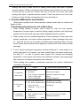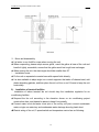
1
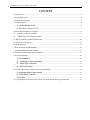
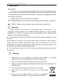
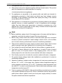
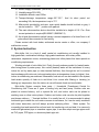
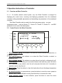
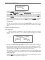
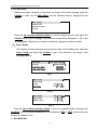
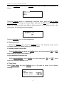
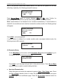
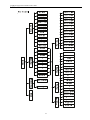
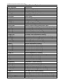
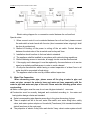
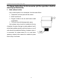
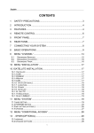
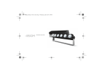
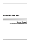
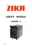
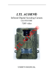
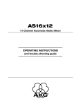
Mini-Chiller Installation and Operation Manual This Manual is applicable to following units: HLR35SM/NaA-M HLR45SM/NaA-M Note: All the pictures in this manual are just schematic diagrams. The actual product is the standard. INC.OF ZHUHAI GREE ELECTRIC APPLIANCES, Address: Jinji West Rd. Zhuhai 519070,Guangdong, China Website: http://www.gree.com Installation and Operation Manual of Mini Chiller CONTENT 1. Usage Notice ...........................................................................................................................................2 2. System Instruction ...................................................................................................................................4 3. Product Specifications .............................................................................................................................5 4. Unit Introduction .....................................................................................................................................6 1).Outline Sketch of Unit................................................................................................................6 2). Outer Wiring Diagram of Unit........................................................................................................7 5 Operation Instructions of Controller.........................................................................................................9 5.1 Overview on Wired Controller ...........................................................................................................9 5.2 Control Panel of the Wired Controller ................................................................................................9 5.3 Wired Controller Operation Instructions .............................................................................................10 5.4. Reset (for erasing error)......................................................................................................................22 5.5 Menu Structure ....................................................................................................................................23 6. Daily Operation and Maintenance .........................................................................................................26 7. Common Malfunction and Solution ......................................................................................................27 8. Terminal Facilities and Selection Guideline ..........................................................................................28 9. System Installation.................................................................................................................................29 1). Unit Installation...........................................................................................................................29 2). Installation of terminal facilities .............................................................................................30 3). Water Pipe Connection ..........................................................................................................31 4).Anti-frozen Notice ....................................................................................................................34 10. System Adjustment (it shall be done by professional).........................................................................34 1). discharge water to water system.............................................................................................34 2). Check Before Trial Run.............................................................................................................34 3).Trial Run .......................................................................................................................................35 11. Usage Instruction for Accessories (all the operation shall be done by professional) …………… ….36 1 Installation and Operation Manual of Mini Chiller 1. Usage Notice Dear Users: Thank you for choosing our Household (Townhouse) Central Air Conditioning Unit. Please read this manual carefully before installation, and conduct installation and usage by following the process instructed in this manual, so that you can comprehensively know and correctly use this unit. Specially remind you the meaning of following label: ! Warning! Means incorrect operation may cause injuries and deaths or badly hurt. ! Notice! Means incorrect operation may cause injuries or property loss. ! Warning! When using this unit in winter, if outer ambient temp. is lower than 0℃, the temperature at where indoor unit is installed should be approach to outdoor ambient temperature; or if there is no people in the room for long-time, indoor temperature will approach to outer ambient temperature: ■ Add antifreeze in water system. Refer the actual outdoor ambient temperature for add proportion. ■ To cooling only unit, when it is not used in winter, drain out water in the unit and pipe to present pipe heat exchanger, pipeline and water pump from breaking; if it is not sure whether water in pipeline is drained clearly, do add antifreeze into the system pipeline. And all of these must be done by professional personnel. ■ Don’t cut off power when unit is off, otherwise auto antifreeze operation protection will be ineffective. ! Warning! 1. Please have the unit installed by authorized service center. For improper installation may cause water leakage, electric shock and fire etc. 2. Don’t use or store flammable and explosive products near the unit. 3. Please cut off power supply immediately when malfunction (such as burning odor is smelled) occurs. 4. Don’t insert finger or things into exhaust vent or air-in grille. 5. Don’t turn on or cut off the unit by turn on or cut off the power supply. 6. Don’t refit the unit. Please contact with dealer or professional installation personnel when it is going to repair or move the unit. 2 Installation and Operation Manual of Mini Chiller 7. The appliance shall not be used for children without supervisor. 8. This product must not be disposed together with the domestic waste. This product has to be disposed at an authorized place for recycling of electrical and electronic appliances. 9. For appliances not accessible to the general public and which are intended to permanently connected to fixed wiring and which may have leakage currents exceeding 10 the installation instructions shall specify the rating of the residual current device (RCD) to installed. 10. This appliance is not intended for use by persons (including children) with reduced physical, sensory or mental capabilities, or lack of experience and knowledge, unless they have been given supervision or instruction concerning use of the appliance by a person responsible for their safety. Children should be supervised that they do not play with the appliance. ! Note! 1. Before installation, please check if the supply power is the same with that listed on nameplate, and check the safety of power. Done by professionals. 2. Before using, please check and confirm if wires and water pipes are connected correctly to present occurrence of water leakage, electric shock or fire etc.Make sure it must be done by professional of central air conditioning installation. 3. There must be earth wire at power supply to prevent electric shock. Don’t connect earth to gas pipe, water pipe, lightning rod or connection wire of telephone. 4. Don’t operate the unit with wet hand, and don’t allow children to operate the unit. 5. The On/off in Owner’s Manual is for the operation to “on and off” button of control panel for users; cut off power means to stop supplying power to the unit. Don’t directly expose the unit under the corrosive ambient with water or dampness. 6. Don’t directly expose the unit under the corrosive ambient with water or dampness. 7. Do conduct electric leakage detect after installation by professional of central air conditioning installation. 8. Operation conditions: Ambient outdoor temperature for heat pump operation must be from -15℃ to 28℃; At the same time, Ambient outdoor temperature range for cooling operation must be from 16℃ to 48℃;Furthermore, water temperature must be under 50℃.In order to avoid freezing the Tube-in-tube heater exchanger, water temperature must be beyond 5℃. 9. To be in compliance EN 61000-3-11,the product shall be connected only to a supply of the system impedance:|Zsys|=0.391 ohms or less.Before connect the product to public power network, please consult your local power supply authority to ensure the power network meet above requirement. 3 Installation and Operation Manual of Mini Chiller 10. 11. 12. 13. Electric supply tolerances: (380-415V)±10%, (50±1)Hz Humidity range:30%-95% Installation altitude: max 1000m Transport/storage temperature range:-25℃-55℃. And for short period not exceeding 24h, the temperature is up to 70℃ 14. Main switch provided by end user: main switch handle should be black or gray, it can be locked in “OFF” position with padlock. 15. The main disconnection device should be installed at a height of 0.6-1.7m. Over current protection is required(EN 60947-3,EN60947-2) 16. An all-pole disconnection switch having a contact separation of at least 3mm in all poles should be connected in fixed wiring Please contact with local dealer, authorized service center or office, our company if malfunction occurs. 2. System Instruction Mini-chiller Unit is a kind of small central air conditioning unit usually installed in high-grade flats, combination buildings, high-grade townhouse, and unitary office, restaurants, department stores, entertaining places and other places that have special air conditioning requirements. Working principle of mini-chiller Unit: Firstly, the unit produces cooled (or heated) water, after being press by water pump, this cooled (heated) water will be transferred to every indoor fan coil by water pipe (or other terminal facilities), then through fan coil to conduct heat exchange with indoor air circle and make indoor air temperature lower (or higher), thus, indoor air conditioning can achieved. Meanwhile, fresh air unit can be installed in the system, lead certain quantity of fresh air in and blow it into rooms after filtering or lowering (or heating up) temperature, then the indoor air can still remain fresh and comfortable. Mini-chiller System consists three parts: ① Household (Townhouse) Central Air Conditioning Unit: There are 2 types of cooling only and heat pump. Outdoor units are placed at outdoor balcony, roof or special flat roof; and indoor units can be placed in washing room or other indoor places. Outdoor and indoor units can also be piled together and places outdoors. ② Terminal facilities: It is usually fan coil, it is recommended to adopt horizontal type invisible fan coil under common circumstance, for it can be easily combined with indoor decoration, and will always produce satisfying effect; ③ Water system: For connecting host and terminal fan coil and work for transferring cool and heat. It is commonly made with galvanized pipe or seamless copper pipe, it can also adopt new type pipes such as PVC pipes, PPR pipes, or aluminum-plastic pipe etc.. 4 Installation and Operation Manual of Mini Chiller 3. Product Specifications 1. Humanized design, both split installation and whole installation are available. 2. Ultra-thin indoor unit design, height is only 288mm, convenient for hanging. 3. Adopting junction box heat exchanger, unit performance, antifreeze ability and reliability can be enhanced greatly. 4. System realized trinity: A set of heat pump system can both cool and heat, it saves gas system, and also collocate with household fireplace, water boiler or city heating net. Thus, cooling, heating, and water heating become trinity. 5. Large range of cool water and heat water supply: When cooling, supply range for cool water is 7℃~12℃; when heating, supply range for heat water is 45℃~50℃. 6. High reliability: Heat transfer media of this unit is water and with no distance limitation, only considering enough water pump lift can realize long-distance heating and cooling. 7. Control function in subrooms: It is available to conduct on or off control to host in rooms, that is, when order of turning on from only a single room, host on; when all rooms send unit off order, host off; general control spot can be set at living room to conduct prior control to unit. 8. Easy operation: Adopting advanced total computer control system, main control system can conduct complete control to the unit. Since it is very easy and quick to reset the operation, it can satisfy users’ requirements. With multi-point control function, it is available to control on/off of host from several rooms, i.e. when order of unit on from only a single room, host on; when all rooms send unit off order, host off; general control spot can be set at living room to conduct prior control to unit. 9. Easy dialogue interface: Host displays in English, and every operation data can be find. When malfunction occur, unit will displays error informational automatically, thus, repair and maintenance is very easy. 5 Installation and Operation Manual of Mini Chiller 4. Unit Introduction 1).Outline Sketch of Unit ◇Outline dimension diagram of HLR35SM/NaA-M、HLR45SM/NaA-M: 1760 Unit: mm G1-1/2" G1-1/2" Water Inlet Water Outlet 1290 710 1750 800 6 Installation and Operation Manual of Mini Chiller 2). Outer Wiring Diagram of Unit COM2 COM2 ◆ Wiring Diagram of HLR35SM/NaA-M、HLR45SM/NaA-M 7 COM1 Installation and Operation Manual of Mini Chiller ◆ Selection of power supply wiring and air switch: Model Power supply type air switch (A) power supply cord HLR45SM/NaA-M 3Ph 63 H07RN-F 5G10.0mm2 HLR35SM/NaA-M 3Ph 50 H07RN-F 5G6.0mm2 Note: 1.The power supply wire must be copper core wire, and the working temperature can not be higher than limited value. 2.If the length of power supply wire is longer than 15meters, do please increase the section area to avoid any accident due to over-load. 3. If the supply cord is damaged, it must be replaced by the manufacturer or its service agent or a similar qualified person in order to avoid a hazard. 4. The appliance shall be installed according to national regulations 5. When installing the connection wiring for manual controller, the wire must be put inside a separate protective sheath to avoid direct sunshine. 8 Installation and Operation Manual of Mini Chiller 5 Operation Instructions of Controller 5.1 Overview on Wired Controller In a 1~16 module network control system, only one Wired Controller is arranged for displaying the control menu, receiving and displaying parameters from the mainboard controller, setting adjustable parameters and transmitting set parameters to the mainboard controller. This Wired Controller also be used in the other heat pump system,so some temperature points (such as Suction T1 ,Suction T2 ,Throttle T1,Throttle T2 )and EEV parameter is not used in this heat system; 5.2 Control Panel of the Wired Controller 1 2 XXXX-XX-XX Power C Series Chiller Cool【Heat/Defrost】 Run 【Manual/Timer】 3 X XX:XX On【Off】 XModules【 10 】 Error On/Off Reset ▲ ▼ 4 5 6 7 Exit Confirm 8 9 1.Power indicator(red): the indicator is on when the Wired Controller is powered on, or otherwise it is off. 2.Run indicator(green): the indicator is on when the Wired Controller is started, or otherwise it is off. 3.Error indicator(red): The indicator is on when the unit is at fault, or otherwise it is off. 4.On/Off button: For controlling unit conversion between start and stop, press the button (for 3 seconds) in stop state to start the unit and press the button (for 3 seconds) in operation state to stop the unit. 5.Reset button: Press the button to clear fault and relieve the air discharge temperature sensor locking. 6.Up selection button: in menu selection, press the button to move the cursor upward or leftward; and in data modification mode, press the button to increase the value. 7.Down selection button: In menu selection, press the button to move the cursor 9 Installation and Operation Manual of Mini Chiller downward or rightward; and in data modification mode, press the button to decrease the value. 8.Exit button: Press the button to go back to the previous menu. 9.Confirm button: In menu selection, press the button to confirm the selected item; and in data modification mode, press the button to confirm the parameter and move the cursor. 10.LCD: Information display zone. 5.3 Wired Controller Operation Instructions 5.3.1. Turning on/off of the Unit The unit under non-commissioning state can be turned on/off via the manual mode or the timing mode. The manual mode is given priority to the timing mode. ●Manual mode: 1)、Manual start: in the unit stop state, press the on/off button for 3 seconds and start the unit, and at that time the operation indicator is on. When the compressor begins to run after a delay, the manual starting process is finished. 2)、Manual stop: in the unit operation state, press the on/off button for 3 seconds and stop the unit, and at that time the operation indicator is off. When the unit stops, the compressor immediately ceases and the cooling tower fan, the cooling pump and the chilled water pump are shut off. The manual stop process is finished. When ambient temperature is lower than -16℃, pressing the start/stop button, the following prompt window comes up on the manual operator. No ON/OFF Under low ambient Temp. OK Press the Confirm button for acknowledgement. If ambient temperature sensors of all linked units are at fault, pressing the on/off button, the following prompt window comes up on the manual operator. No ON/OFF under all ambient temp. sensor fail! OK Press the Confirm button for acknowledgement. In the manual defrosting mode, pressing the on/off button, the following prompt window comes up on the manual operator. 10 Installation and Operation Manual of Mini Chiller Don’t ON/OFF under manual defrost! OK Press the Confirm button for acknowledgement. By pressing the up selection button or the down selection button, you can convert between YES and NO. Press the Exit to quit selection and go back to home page. When the unit is in the cooling & heat recovery mode stop state, if you select YES and press the Confirm, you can go back to the home page and the unit is in the heating & heat recovery operation state; and if you select NO and press the Confirm, you can go back to the home page and the unit is in the cooling & heat recovery operation state. ●Timing mode: After the unit is energized or reset, press the Manual Mode to turn on/off the unit. Conversion between the manual mode and the timing mode is detailed in 5.3.2.2 Main Menu 5.3.2 Menu Operation Instructions 5.3.2.1 Home page When the controller is powered on, the microcomputer will make a 3-second automatic detection and the LCD on the wired controller will display the following content. XXXX-XX-XX X XX:XX C Series Chiller Cool【Heat/Defrost】 On【Off】 XModules【 【Manual/Timer】 】 The content of default home page menu is dependent on system state. XX stands for year, month, day, hour and minute. Only one item or none is displayed in the“【】”, representing the start/stop state of the system, starting method and quantity of linked modules. Presence of the at the end means the system is at fault. After entering into a menu item, if no operation is made on the Wired Controller within 10 minutes, the system will automatically go back to the above default home page menu (Home Page). Press the Exit button on the wired controller at any time for enough times, you can go back the default home page menu as shown above. 11 Installation and Operation Manual of Mini Chiller 5.3.2.2 Main Menu When home page is present on the screen as shown in the above drawing, press the Confirm to enter into the Main Menu and the following items is displayed on the screen. User’s Setup Module View Parameter Setup Version Press the up or down selection button to choose required function and press the Confirm button to go to the page. Only one item or none will be displayed in 【】 in the following graph. When a line or number is selected, it appears as white on black. (1)、User’s Setup The following is basic settings most common for users. On the Main menu, select the User’s Setup and press the Confirm to go to the sub-menu, as shown in the following drawing. Run Mode Startup Auxiliary Heat Auto-Antifreeze 【Cool / Heat /Defrost】 【Manual/Timer】 ON【OFF】 ON【OFF】▼ Page 1 Timer Setup Clock Setup Sound Backlight ▲ ON【OFF】 ON【OFF】▼ Page 2 ECO.Model Quiet Model Memory Start ON【OFF】▲ ON【OFF】 ON【OFF】 Page 3 Press the Up or Down selection button to choose a needed function and press the Confirm to go to or confirm the selection. The subsequent “ON” or “OFF”, which means the function is selected or not. a、Run Mode Set 12 Installation and Operation Manual of Mini Chiller Select the Run Mode and press the Confirm button, and the display on the screen is as follows: Cool Heat Defrost Press the Confirm button to acknowledge a selected object, press the Up or Down selection button to change a selected object, and press the Exit button to cancel the model set. Different models have different display modes.If you is setting a mode in the startup state, the following prompt will appear: Set mode only when unit is off! OK Press the Confirm button for acknowledgement b. Startup mode set Select the Startup and press the Confirm button. The start/stop mode can be converted between the manual mode and the timing mode. c. Auxiliary Heater Function Set Select Auxiliary Heat and press the Confirm button, and the subsequent “ON” or “OFF”, which means the function is selected or not. d. Auto-Antifreeze Protection Set Select Auto-Antifreeze, press Confirm, and the subsequent “ON” or “OFF”, which means the function is selected or not. e. Timer Setup Select Timer Setup and press Confirm to go to the page as shown in the following drawing: Timer Setup XXX Timer On XX:XX Timer Off XX:XX 13 ON【OFF】 ON【OFF】 Installation and Operation Manual of Mini Chiller Press Confirm to change a selected object. Press Up or Down to change value or state of a selected object. This is timing on/off time and effective status each week. “OFF” represents the time set is invalid and “ON” means a valid time set. Press the Exit button to quit the page and go back to the previous menu and save set values. f. Clock Setup Select Clock Setup and press the Confirm button to go to the page. The following display is present on the screen. Clock Setup 20XX-XX-XX XX:XX XXX Press the Confirm button to change a selected object. Press the Up or Down button to change value or state of a selected object. Press the Exit button to quit the page and go back to the previous menu and save set values. g. Sound On set Select Sound, press the Confirm button, and the subsequent “ON” or “OFF”, which means the function is selected or not. h. Backlight On Set Select Backlight, press the Confirm button, and the subsequent “ON” or “OFF”, which means the function is selected or not. I . ECO.Model Set Select ECO.Model , press the Confirm button, and the subsequent “ON” or “OFF”, which means the function is selected or not. J Quiet Model Set Select Quiet Model , press the Confirm button, and the subsequent “ON” or “OFF”, which means the function is selected or not. K Memory Start Set Select Memory Start, press the Confirm button, and the subsequent “ON” or “OFF”, which means the function is selected or not. The function is for selecting whether the unit will memorize its operation state if power supply is shut down. (2). Module View When the Main Menu is present on the screen, select Module View, press the Confirm to go to the pages as shown in the following drawing. 14 Installation and Operation Manual of Mini Chiller Module 1 Module 2 Module 3 Module 4 EXIST【NO】 EXIST【NO】 EXIST【NO】 EXIST【NO】▼ Page 1 Module 5 Module 6 Module 7 Module 8 EXIST【NO ▲ EXIST【NO】 EXIST【NO】 EXIST【NO】 ▼ Page 2 Module 9 Module 10 Module 11 Module 12 EXIST【NO】 ▲ EXIST【NO】 EXIST【NO】 EXIST【NO】 ▼ Page 3 Module 13 Module 14 Module 15 Module 16 EXIST【NO】 ▲ EXIST【NO】 EXIST【NO】 EXIST【NO】 Page 4 Press the Exit to quit the page and go back to the previous menu. Press the Up or Down button to select a needed module and press the Confirm button to go to corresponding page. A module followed with “ ”means having a failure. The following menu will display after going to the module. Temp. View State View Error View Manal Defrost X Press the Exit button to quit the page and go back to the previous menu. Press the Up or Down selection button to select a needed function and press the Confirm to go to corresponding page. “X”stands for one number of “1~16”, meaning number of the selected module. The “ ”following the State View represents the module provides auto freeze protection operation or defrosting operation. The “ ”following the Error 15 Installation and Operation Manual of Mini Chiller View represents the module is at fault. a、Temperature View The function is for checking temperature at various temperature points. Select Temp. View and press the Confirm button to go to the pages as shown in the following drawings. C Water Tin C Water Tout H Water Tin H Water Tout XXX.X℃ XXX.X℃ XXX.X℃ XXX.X℃ ▼ Page 1 Defrost T1 Defrost T2 【Anti-Fre.T/Anti-HeatT】 Ambient T XXX.X℃ ▲ XXX.X℃ XXX.X℃ XXX.X℃ ▼ Page 2 Suction T1 Suction T2 Exhaust T1 Exhaust T2 XXX.X℃ ▲ XXX.X℃ XXX.X℃ XXX.X℃ ▼ Page 3 Throttle T1 Throttle T2 XXX.X℃ XXX.X℃ ▲ Page 4 Press the Up or Down selection button to convert among the above four pages. Press the Exit button to quit the menu page and go back to the previous menu. When page 1 is present on the screen, press the Reset button and the Exit button simultaneously for 3 seconds, and C Water Tin and H Water Tin, as displayed previously, will be converted to C Aver.Tin and H Aver.Tin. And press again the Reset button and the Exit button simultaneously for 3 seconds, and C Water Tin and H Water Tin will be displayed again. As such, display can be converted between water inlet temperature and water inlet average temperature. Only one item will be displayed in 【】 in page 2.When the run mode is cool or defrost, 【 Anti-Fre.T/Anti-HeatT 】 shows Anti-Fre.T; When the run mode is heat, 16 Installation and Operation Manual of Mini Chiller 【Anti-Fre.T/Anti-HeatT】shows Anti-HeatT. Note: above temperature display is dependent on unit model. If the temperature sensor is not existent for a certain model, “None” would be present on the display zone for corresponding temperature point. b、State View Used for checking the on/off status of motors. Select the State View and press the Confirm to go to the pages as shown in the following drawings. Fan 1 Fan 2 Fan 3 Sys.State ON【OFF】 ON【OFF】 ON【OFF】 【Cool/Heat/Defrost/Anti-fre.】 ▼ Page 1 Compressor 1 Compressor 2 C Water Pump H Water Pump ON【OFF】 ▲ ON【OFF】 ON【OFF】 ON【OFF】 ▼ Page 2 Ass. Heat 1 Ass. Heat 2 4-Valve 1 4-Valve 2 ON【OFF】 ▲ ON【OFF】 ON【OFF】 ON【OFF】 ▼ Page 3 EXV. 1 ▲ XXX Step XXX Step EXV. 2 ▼ Page 4 Exthalpy Inc.EXV. 1 XXX Step Exthalpy Inc.EXV. 2 XXX Step ▲ ▼ Page 5 17 Installation and Operation Manual of Mini Chiller Dis. T Sensor 1 【Lock/Unlock】 Dis. T Sensor 2 【Lock/Unlock】 ▲ ▼ Page 6 Water_Out EXV. Water_In EXV. ON【OFF】 ON【OFF】 ▲ Page 7 Press the Up or Down selection button to convert among the above pages. Press the Exit button to quit the menu page and go back to the previous menu. Note: above temperature display is dependent on unit model. If the temperature sensor is not existent for a certain model, “None” would be present on the display zone for corresponding temperature point. c、Error View Used for checking the failure status of the system. Select the Error View and press the Confirm to go to the pages as shown in the following drawings. Present Error History Error Clear History Error Press the Exit button to quit the page and go back to the previous menu. Press the Up or Down selection button to choose a needed module. When Present Error or History Error is selected, press the Confirm to go to the following interface. XXXXXX XXXXXX XXXXXX XXXXXX “XXXXXX”are possible failures as listed in the following: 18 Installation and Operation Manual of Mini Chiller Comp.1 HP Pro Dis T Sensor 2 Comp.1 OverLoad Pro C Water-in Sensor Fan1 OverLoad Pro C Water-out sensor Sys.1 Dis.HighTemp. Anti-Frozen Sensor C Water Flow Switch Defrost T Sensor1 Fan3 OverLoad Pro Defrost T Sensor2 Jumper Error Ambient T Sensor Com.2 HP Pro Dis. T Sensor1 Comp.2 OverLoad Pro Dis. T Sensor2 Fan2 OverLoad Pro Thr. Valve1 Sensor Sys.2 Dis.HighTemp. Thr. Valve2 Sensor H Water Flow Switch Suction T Sensor1 Comp.1 LP Pro Suction T Sensor2 Comp.2 LP Pro LP Sensor1 Error User Anti_fire Pro LP Sensor2 Error Dis T Sensor 1 H Water-in Sensor H Water-out Sensor If the last line on the menu is followed with a “▼”, more failures are available below. You can press the Down selection button for reading more failures. If the first line is followed with a “▲”, more failures are available above. You can press the Up selection button for reading more failures. Press the Exit button to go back to the previous menu. Only the lasted four failures are remained even if quantity of history failures is more than 4, In Fig. 3.2.3.1, select Clear History Error and press the Confirm button to go to the following interface. Clear History Error NO YES Press the Up or Down selection button to convert between NO and YES. Press YES to confirm and press NO to quit the menu and go back to the previous menu. d. Manual Defrost Used for starting or stopping manual defrosting. Select Manal Defrost and press Confirm to go to the following page. MANUAL DEFR. SYS. DEFR. Anti-Fre.T X ON【OFF】 ON【OFF】 XXX.X℃ Press Confirm to start or stop manual defrost and press Exit to quit the interface and go 19 Installation and Operation Manual of Mini Chiller back to the previous menu.When manual defrost is on and the two systems do not stop defrosting completely, the following prompt will come up. Do you need to stop Unit under defrost? YES NO Press Up or Down button to convert between YES and NO, press Confirm for acknowledgement, press Exit to quit the menu and go back to the previous menu. Note: manual defrost is not allowed for two modules simultaneously. If manual defrost is started for one module and such function is started for another module, the following prompt will appear: MOD.X is defrosting Don’t start current mod now! YES NO Press YES for acknowledgement. If manual defrost is initiated for a certain module under non-manual defrost mode, the following prompt will be present: Please set the mode To defrost ! OK (3) Parameter Setup On the Main Menu on the screen, select Parameter Setup and press Confirm to go to the page as shown in the following drawing. User Para. Setup System Para. Setup Press Exit to quit the page and go back to the previous menu. Press Up or Down selection button to select a needed setting interface. a、User-level Parameter Set Select the menu and confirm the selection for going to User Para. Setup menu. Press the Up or Down selection button to select the parameter to be modified and press Confirm to go to the modification page. Press the Up or Down selection button for 20 Installation and Operation Manual of Mini Chiller entering parameters and press Confirm or Exit to go back to the parameter set menu. Other parameters can be modified in the same way. After entered Default Parameter option, System will inquire whether use Default Value, if YES is choosed, then the parameters will be modified to Factory Default Value。After modification, press the Up or Down selection button to save parameter and quit the item. A prompt for asking whether to save the modification comes up again on the screen. Select Confirm to save it and go back to the Main menu. Please note that only in the above exit way can modifications be saved. b、System-level Parameter Set User shall not use the function unless under instruction of debug personnel if necessary, to prevent an accident. Code entry is essential for operating the function. Button points on how to operate: select the menu and confirm the selection, and a prompt of code entry appears on the screen; press the Up and Down selection buttons to enter correct password, press Confirm to confirm it, and go to Parameter Set Menu; press the Up and Down selection buttons to select parameters to be modified, press Confirm to go to modification interface, press the Up and Down selection buttons to enter parameter value, and press Confirm or Exit to go back to the Parameter Set menu; other parameters can be modified in the same way; After entered Default Parameter option, System will inquire whether use Default Value, if YES is choosed, then the parameters will be modified to Factory Default Value。after modification, press the Up and Down selection buttons to select Save and Exit item under the Parameter Set menu, and a prompt whether to save the modified values comes up again on the screen, and if you need to save them, you can select OK and then press Confirm to save modifications and go back to the Main menu. Please note that only in the above exit way can modifications be saved. (4)、Version Information Used for checking version number of software and hardware of the wired controller. On the Main menu on the screen, select Version and press Confirm to go to the page as shown in the following drawing. Ver.: XXX Data: XXXX.XX Press Exit to quit the page and go back to the previous menu. 21 Installation and Operation Manual of Mini Chiller 5.4. Reset (for erasing error) On any interface, press Reset, the following page appears: Clear Error Remove Dis Sensor Press Exit to go back to the previous interface and press Confirm to select function as shown in the following: 5.4.1 Erasing Error Error is clear ! OK Press Confirm to confirm it and go back to the previous page. 5.4.2 Relieve Discharge Temp. Sensor locking Press Confirm to go to Code Entry page and enter correct password to go to the following page Temp. Sensor Error Is Clear ! OK Press Confirm to confirm it and go back to previous page. 22 Installation and Operation Manual of Mini Chiller 5.5 Menu Structure 23 Installation and Operation Manual of Mini Chiller Menu Structure User’s Setup Run Mode Startup Auxiliary Heat Auto-Antifreeze Timer setup Clock Setup Sound Backlight ECO. Model Quiet Model Memory Start Module View Temp. View C Water Tin C Water Tout H Water Tin H Water Tout C AVER. Tout H AVER. Tout Defrost T1 Defrost T2 Anti-Heat T Ambient T Suction T1 Suction T2 Exhaust T1 Exhaust T2 Throttle T1 Throttle T2 State View Fan1 Fan2 Fan3 Sys.State Compressor1 Compressor2 C Water Pump H Water Pump Ass. Heat 1 Ass. Heat 2 4-Valve 1 4-Valve 2 EXV. 1 EXV. 2 Exthalpy Inc EXV.1 Menu Structure Explanation Explanation Function setting Running modes selection Startup and stop selection Auxiliary heat function selection Auto anti-freezing function selection Timer setting Time setting Buttons sound setting Backlight turn on setting Energy saving mode setting Quiet mode setting Memory function setting when power on/off Corresponding modular’s parameters/status checking Corresponding modular’s temperatures checking Water inlet temperature checking Water outlet temperature checking Hot water inlet temperature checking Hot water outlet temperature checking Water inlet modular average temperature checking water inlet modular average temperature checking Defrosting temperaure 1 checking Defrosting temperaure 2 checking Anti-overheat temperature checking Ambient temperature checking Suction temperature 1 checking Suction temperature 2 checking Exhuast temperature 1 checking Exhuast temperature 2 checking Throttle temperature 1 checking Throttle temperature 2 checking Corresponding modular status checking Fan motor 1 status checking Fan motor 2 status checking Fan motor 3 status checking Units system status checking Compressor 1 status checking Compressor 2 status checking Water pump status checking Hot water water pump status checking Auxiliary electic heating 1 status checking Auxiliary electic heating 2 status checking Four-way valve 1 status checking Four-way valve 2 status checking Electric Expansion valve 1 number of steps checking Electric Expansion valve 2 number of steps checking Exthalpy electric expansion valve 1 number of stpes 24 Installation and Operation Manual of Mini Chiller Exthalpy Inc EXV.2 Dis. T Sensor 1 Dis. T Sensor 2 Water_Out EXV. Water_In EXV. Error View Comp.1 HP Pro Comp.1OverLoad Pro Fan1 OverLoad Pro Sys.1 Dis.HighTemp. C Water Flow Switch Fan3 OverLoad Pro Jumper Error Com.2 HP Pro Comp.2 OverLoad Pro Fan2 OverLoad Pro Sys.2 Dis.HighTemp. H Water Flow Switch Comp.1 LP Pro Comp.2 LP Pro User Anti_fire Pro Dis T Sensor 1 Mal. Dis T Sensor 2 Mal. C Water-in Sensor C Water-out sensor Anti-Frozen Sensor Defrost T Sensor1 Defrost T Sensor2 Ambient T Sensor Dis. T Sensor1 Dis. T Sensor2 Thr. Valve1 Sensor Thr. Valve2 Sensor Suction T Sensor1 Suction T Sensor2 LP Sensor1 Error LP Sensor2 Error H Water-in Sensor H Water-out Sensor Parameter Setup User Para. Setup Cool T_in Heat T_in AH T_Start AH T_Stop H Water T_in checking Exthalpy electric expansion valve 2 number of stpes checking Exhaust sensor 1 status checking Exhaust sensor 2 status checking Water-out electromagnetic valve status checking Water-in electromagnetic valve status checking Error checking Compressor 1 high pressure protection Compressor 1 over current protection Fan motor 1 over current protection System 1 air exhaust high temp. protection Water flow switch protection Fan motor 3 over current protection Jumper error Compressor 2 high pressure protection Compressor 2 over current protection Fan motor 2 over current protection System 2 exhaust high temperature protection Hot water water flow switch Compressor 1 low pressure protection Compressor 2 low pressure protection User side anti-freezing protection Exhaust sensor 1 fail Exhaust sensor 2 fail Water in sensor malfunction Water out sensor malfunction Anti-freezing sensor malfunction Defrosting sensor 1 malfunction Defrosting sensor 2 malfunction Ambient sensor malfunction Air exhaust sensor 1 malfunction Air exhaust sensor 2 malfunction Throttle valve 1 sensor malfunction Throttle valve 2 sensor malfunction Suction sensor 1 malfunction Suction sensor 2 malfunction Low voltage sensor 1 malfunction Low voltage sensor 2 malfunction Hot water in sensor malfunction Hot water out sensor malfunction Prarameters setting Parameters setting for users Water inlet temperature setting Heating water inlet temperature setting Auxiliary Heat startup temperature setting Auxiliary Heat stop temperature setting Hot water inlet temperature setting 25 Installation and Operation Manual of Mini Chiller System Para.Setup DEF.T_Start DEF.T_Stop DEF.Space DEF.Time Anti-Freeze Anti-Heat Temp.Rate Com.Space System parameters setting Defrosting startup temperature Defrosting stop temperature Defrosting interval Defrosting time Anti-freezing temperature Anti-overheat temperature Water inlet temperature change rate Compressor interval 6. Daily Operation and Maintenance When adjustment and test had completed, daily operation such as turn on/off unit, switch cooling and heating, and set parameter etc. are to be done through the manual control that installed indoor. ★ All safety protection settings in the unit are set well before outgoing, please don’t modify them to avoid damaging the unit. ★ The on/off control to fan coil in every room should be operated individually by temp. controller and the 3-speed switch installed in every room. When there is no connect control between host and fan coil, after the last fan coil is turned off, host should stop. ★ Don’t cut off power immediately after unit had stopped. If the unit stopped and disconnected to power supply for more than 2 days, please switch on the power supply for more than 6h before restart the unit. Otherwise, the unit may not be able to operate normally. ★ Don’t put things on the unit or its accessories, keep all around dry, clean and well ventilation. Clean it on time by professional personnel when there is much dust on fin of condenser to prevent the dust from affecting the performance. ★ Don’t block the air outlet and air intake vents of indoor fan coil, filter at air intake vent should be disassembled and cleaned regularly. (it shall be done by professional) ★ Do add antifreeze into water system of heat pump unit, the additional proportion is shown in this manual on page 26. Please let the professional to add the antifreeze. Please cut off the power supply before adding the antifreeze. For cooling only unit, when it is not used in winter, do drain out all water in the unit and pipeline to prevent the tube-in-tube heat exchanger, pipes and pump from breaking; when it is not sure water in pipeline had drained completely, do add antifreeze into system pipeline. Don’t cut off power supply when turn off the unit, otherwise auto antifreeze operation protection will be useless. ★ To heat pump unit, if not for use for a long time, water in the pipeline will be the same temperature as ambient water. In that case, cool air may blow out in winter when unit begins to operate in heating mode. If there is no connected control system between host and fan coil, it is better to turn on host 5~10min before turning on the unit for 26 Installation and Operation Manual of Mini Chiller heating, then turn on indoor fan coil to heating mode directly after water in pipeline become warmer; if there is connected control between host and fan coil, turn on a fan coil first and turn on host for 5~10min, then turn on the fan coil in room that needs heating after water in pipeline become warmer. These can prevent cool wind from blowing out in the first few minutes when fan coil is just turned on. 7. Common Malfunction and Solution When there is problem occur during operation, please contact with our nearest local dealer or office. The following phenomena are not malfunctions: 1. When cooling (heating in winter), load is small (i.e. little fan coils operate), temperature of system water is lowered (raising) rapidly, antifreeze (anti high-temp) protection will work and will stop when water temperature back to set point. 2. When heating, since the surface temperature of heat exchanger is lower than outer ambient temperature, and when surface temperature of heat exchanger lower than 0℃, there will be frost on the surface and affect heat exchanging effect, thus the control system would conduct defrost regularly to melt the frost on the surface of heat exchanger. 3. If unit is used at area where temperature at winter will below 0℃, when system is in waiting state (don’t cut off power), and when ambient temp. and system water temp. are about 0℃, in order to prevent water system from freezing and damaging equipments, control system will conduct auto antifreeze operation, start water pump and compressor until water temperature reach safe point. When dealing with problems, professional personnel can remove malfunctions according to following list: Common error Reason Solution (done by professionals) A、 Error on power 1. Compressor doesn’t work. 2. Fan noise is large B、 Wire loose ●Check and re-tighten C、 Error on relay or insurance ●Check error reason and repair D、 Temp. is set too high ●Reset E、 Error on compressor ●Change compressor A、 Fan fixing bolts are loose ●Retighten fan fixing bolt B、 Fan louver touched outer ●Check reason and adjust case or net cover ●Change fan C、 Operation of fan is not steady A、 Liquid hit produced when 3. Compressor noise is large ●Check is expand value is ineffective, liquid refrigerant flows in temp. sensor is loose, and repair compressor ●Changer compressor B、 Components inside 27 Installation and Operation Manual of Mini Chiller compressor are damaged. 4. Water pump doesn’t operate or operate A、 Error on power or wiring ●Check reason and repair B、 Error on relay ●Exchanger relay C、 There is gas in water pipe ●Exhaust all gas A、 Freon in cooling system ●Check and repair and recharge abnormally Freon. leaks B、 Heat preservation of water 5. Cooling effect is bad. ●Strengthen heat preservation pipe is bad. C、 Water flow quantity is not ●Clean water filter enough D、 Heavy dust on condenser ●Clean condenser E、 Cooling system blocked ●Check or change dry filter 6.Compressor frequently on and off. A、 Too much refrigerant ●Exhaust some refrigerant B、 Circulation of water system ●Water system is blocked or there is air. Check water pump, valve, pipeline, is bad. C、 Low load clean water filter or exhaust air. ●Adjust load or increase energy store facility. 7. Refrigerate system low-pressure switch on/off is working frequently. 8.Compressor operates but unit doesn’t cool. ●Check and repair and recharge A、 Freon leakage on system refrigerant. and refrigerant shortage. B、 Dry filter is blocked ●Change dry filter C、 Error on heat expand ●Check if expanse valve is blocked, temp. sensor is leaking, then repair or valve. change. D、 Water system circulation ●Check water system and solve. is bad. A、 All refrigerant is leaked B、 Freeze evaporator freeze. ●Check, repair and charge refrigerant is ●Check reason and remove freezing ●Change compressor C、 Compressor error 8. Terminal Facilities and Selection Guideline Mini-chiller Terminal Facilities are mainly for the heat exchanger facilities installed indoor, Usually it is fan coil with several models. Such as horizontal invisible fan coil, horizontal visible fan coil, vertical visible fan coil, suspending fan coil and so on. User can select different type of fan coil according to house structure and indoor decoration style. Normally, we recommend selecting horizontal invisible fan coil, because it is in smaller dimension and can be concealed well, it is easy for indoor decoration. At the same time, its noise is lower, and it is relatively cheaper. Suggestions are as following: 28 Installation and Operation Manual of Mini Chiller Models FP-34 FP-51 FP-68 FP-85 FP-102 FP-136 Room area m2 8~12 10~18 15~25 20~30 25~35 30~45 Control to the fan coil at every room is conducted by the temperature control on wall and the 3-speed switch. Temperature control is for setting room temperature, 3-speed switch, with high, medium, and low speeds, for adjusting airflow and cooling capacity of the fan coil. 9. System Installation Do have the unit installed by the authorized company or professional central air conditioning installation project company, don’t try to install it by yourself. 1). Unit Installation ⑴.Select of installation location ★ This Household (Townhouse) unit can be installed on roof, ceiling, special flat or other place that is easy for installation and be able to stand its weight. ★ Select a place with well ventilation and smooth exhausting, and the place will not produce short-circuit circulation, and where exhausted air from the unit will not bother neighbors. ★ When placing the unit at roof, pay attention to wind direction to prevent direct up wind; when placing it on ground, avoid placing it at where there is strong wind. ★ There should be no heat source, exhaust vent of other facilities, strong steam and flammable gas around the unit. ★ When installing several units, ensure there is enough suction space to prevent short-circuit circulation. ★ Place where there is no large snow in winter. ★ There should be no obstruction near air intake vent or air outlet vent. ★ Place where with drainage pipe around the unit to drain cooling or heating water. ★ Place that near power for easy wiring. ★ Place that near supply water source for convenient pipe construction. ★ There should be open space around the unit. ⑵.Installation space requirement for outdoor unit Whole installation: 29 Installation and Operation Manual of Mini Chiller Unit: mm ⑶.Move and disassembly ★ It is better to use forklift or crane when moving the unit. ★ When suspending, please adopt canvas gallus, round the gallus at base of the unit and bundle it tightly, meanwhile, ensure that the gallus would not tough heat exchanger. ★ When moving the unit, the slant angle should be smaller than 30° ⑷.Installation mode ★ Fix the unit on separated concrete base with expand bolts directly. ★ It is also available to adopt angle iron or steel supporter that make off channel steel, add shake-absorbing gaskets, and then place the unit on floor or roof. Ensure to keep the unit horizontally. 2). Installation of terminal facilities Installation of indoor terminal fan coil should obey the installation regulation for air conditioning facilities. ★ Suspend the fan coil according to the elevation shown on air conditioning project construction chart, and please be aware to keep it horizontally. ★ Connect water in/out and water in/out joint of fan coil by soft joint; connect condensate water out pipe on water tray and condensate water drainage hose by plastic host. ★Electric wiring of fan coil, 3-speed switch and temperature control are as following: 30 Installation and Operation Manual of Mini Chiller Electric wiring diagram for no connection control between fan coil and host Special notice: 1、 When connect control is not conducted between fan coil and host, please connect the end-switch at main board with live wire (short connected when outgoing).it shall be done by professional. 2、 Method of shutting off the power is cutting off the air switch. Contact distance between the electrodes of the air switch must be beyond 3mm. 3、 Installation should conform to the local electric standard. 4、 The appliance shall be installed in accordance with national wiring regulations. 5、 Before obtaining access to terminals, all supply circuits must be disconnected. 6、 If the supply cord is damaged, it must be replaced by the manufacturer or its service agent or a similarly qualified person in order to avoid a hazard. 7、 An all-pole disconnection switch having a contact separation of at least 3mm in all poles should be connected in fixed wiring. 8、 The appliance shall not be used by children without supervisor. 3). Water Pipe Connection When connecting water pipe, please screw off the plug at water in pipe and water out pipe, connect the water-in hose and water-out hose separately with the water-in pipe and water-out pipe of the unit. Please note the following points when constructing: ★ Water connect pipes must be new, do not use old pipes instead of new ones. ★ Construction must be correctly designed and conducted according to the water and heat pipeline design criteria and standard. ★ Select corresponding pipe diameter according to the given dimension of pipes. ★ There is expand can set in the unit, water flow switch, auto water filling valve, safety valve, and water system adopts our Household (Townhouse) Unit standard installation sketch (as shown in the next page) ★ The proportion of electric 2-way valve and electric 3-way valve in water system should 31 Installation and Operation Manual of Mini Chiller refer to technical criteria (the recommended value is 2:1). And electric 3-way valve must be assembled at the furthest end of water system. ★ Try to decrease the pressure difference between indoor fan coil or main host with water in or out port of the unit. ★ Do install water filter at water-in pipe of the unit to prevent block at heat exchanger inside the unit. ★ After piping water system, according to relevant criteria for HVAC, conduct leakage test with hydraulic pressure of 0.6MPa. and maintain the pressure for 24h. Ensure that there is no leakage in the whole pipeline system, then wrap heat preservation layer. ★ After completed piping of water system, do drain out contamination inside water system. Ensure that inside of water pipe is clean without contaminations such as rust dregs, so that there will be no blockage in pipeline and sleeve heat exchanger in the unit and water pump, which will damage the unit. ★ Exhaust air inside water system with auto exhaust valve. Auto exhaust valve must be installed at the highest point at water return pipe. ★ Drainage valve should be installed at the lowest point of water pipe. ★ Thermometer and hydraulic pressure meter must be set at water-in and water-out pipe of unit for convenient check when unit is operating. ★ Water pipe must conduct heat preservation and moisture proof, to prevent loss of cooling or heating capacity and forming condensation water. ★ Inlet water pipe pressure must be lower than 0.62MPa. ,otherwise safety valve will open automatically release pressure. At the same time ,its minimal pressure must be beyond 0.15MPa. ★ Cleaning and maintenance must be done by professionals. ! Warning: Water filter with at least 60 meshes must be installed on water-in pipeline system of the unit to avoid blocking the sleeve heat exchanger in the unit and causing damage. Do clean it regularly. It must be down by professionals 32 lift method: Cable through the hole, lift by hook 33 air inlet water air inlet inlet 1750 1290(foundation bolt4-M12) air inlet air inlet 1750X2+300=3800 water outlet >300 water inlet air inlet air inlet air outlet water outlet air inlet >1000 unit mm base rubber isolator concrete base foundation bolt >1200 >1000 air outlet >2000 air inlet >1000 Installation and Operation Manual of Mini Chiller Standard Installation Sketch for this Household (Townhouse) Unit Installation and Operation Manual of Mini Chiller 4).Anti-frozen Notice ★ To heat pump unit, when it is used at where temperature in winter would below 0℃, do conduct heat preservation with insulation material, and add antifreeze according actual situation. ★ On control system there is auto antifreeze operation set for assisting system. Its principle is: When unit is at standby state (don’t cut off power), and ambient temperature and system water temperature is at about 0 degree, control system will start water pump and compressor till water temperature reaches safety point. Thickness of glycol liquid—freezing point list: Thickness % Freezing point ℃ Thickness % Freezing point ℃ Thickness % Freezing point ℃ 4.6 -2 19.8 -10 35 -21 8.4 -4 23.6 -13 38.8 -26 12.2 -5 27.4 -15 42.6 -29 16 -7 31.2 -17 46.4 -33 In the list: Thickness of glycol is mass thickness. 10. System Adjustment (it shall be done by professional) 1). discharge water to water system ★ Fill water to the water pipe, meanwhile, conduct auto gas exhaust from exhaust valve till the whole pipe filled with water, and confirm air in pipe had completely be exhausted. 2). Check Before Trial Run Checking must be done by professional personnel. ★ Check indoor fan coil Check if power cord connection of all indoor fan coils is correct, and rotation direction of fan motor is correct. Check if the valve on entrance and exit pipes of fan coil is completely open. Exhaust it from exhaust valve when there is gas inside fan coil. ★ Check unit Check if the outer appearance of unit and pipeline system is damaged during transportation. Check if wiring terminals for electric components inside unit is loose, if phase sequence is correct. Check if vane of fan motor would touch the outer case and grille when rotating. Check if temperature sensor had inserted well. 34 Installation and Operation Manual of Mini Chiller ★ Check pipeline system Check if valves at pipeline system had open completely. Check if water had filled the whole pipeline system, if air is exhausted completely. Check if heat preservation to pipeline system is well. 3).Trial Run Trial run can only be conducted after passing all above checking, then do it under the guideline of professional personnel. ★ Switch on the power supply and turn on the unit. To the unit that uses 3-phase power, when power sequence is reverse, phase sequence protection works, then fan motor, compressor and water pump will not operate At that time, cut off power first, exchange the two phases among the 3-phase power, then switch on the power supply again and turn on the unit. ★ During operation, circle water pump should operates steadily. If it operates unsteadily, and indicator of pressure meter swings a lot, it means there is air inside water system. At that time, exhaust air completely through exhaust valve and then turn on the unit. After turning on the unit for 3 minutes, fan and compressor start automatically. ★ After compressor had started, when abnormal sound is heard, stop the unit immediately and check. ★ When cooling in summer, when temperature of water-out Tout≥15℃, compressor starts; when Tout≤7℃, compressor stops, and water pump keeps on running. To heat pump unit, when it is operating heating in winter, and if water-out temperature Tout≤45℃, compressor starts running; when Tout≥50℃, compressor stops, and water pump continues running. ★ Obverse if water temperature for in and out is normal, when the temperature difference between water in and out ΔT>5℃, it means water flow in the system is small, at this time, check that whether there is blockage in water filter, air in the pipe had not been exhausted, resistance in pipeline system is too great etc. when ΔT is between 3-5℃, it can achieve best performance. ★ After trial run, clean the filter on pipeline first, and then the unit can begin normal operation. It is necessary to assembly and cleans the filter after a certain period (say, 3 months) to remain normal operation. ★ Note: Since the unit adopts total hermetic scroll compressor, phase sequence of power must be correct, and it is forbidden for operate with reverse power supply for long time. 35 Installation and Operation Manual of Mini Chiller 11. Usage Instruction for Accessories (all the operation shall be done by professional) 1. Auto exhaust valve If air in water system is not exhausted, it would cause effects: Temperature at some parts will be uneven Noise is produced Oxygen contain in the air would cause metal oxygenation Too much air would damage water pump Auto exhaust valve should be installed at the top of pipeline, the place that gas is easily gathered, and it should be installed vertically; self-close valve or cut-off valve should be installed at bottom of exhaust valve, it is convenient for system water fill or is used when repairing; exhaust valve cannot be installed at place that is easy to be frozen. 36