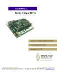
1
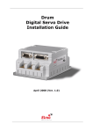
^1 USER MANUAL ^2 3U Servo Drive Amplifier 3U81 and 3U151 ^3 3U-Drives Family Drive Amplifiers ^4 5xx-603555-xUxx ^5 July 28, 2003 Single Source Machine Control Power // Flexibility // Ease of Use 21314 Lassen Street Chatsworth, CA 91311 // Tel. (818) 998-2095 Fax. (818) 998-7807 // www.deltatau.com Copyright Information Original printing 2003. Copyright Delta Tau Data Systems, Inc. - All rights reserved. Printed in the United States of America. Notice: Not for use or disclosure outside of Delta Tau Data Systems, Inc., except under written agreement. All rights reserved. No part of this book shall be reproduced, stored in retrieval form, transmitted by any means, electronic, mechanical, photocopy, recording, or otherwise without the written permission from the publisher. While every precaution has been taken in the preparation of the book, the publisher assumes no responsibility for errors or omissions. Neither is any liability assumed for damages resulting from the use of the information contained herein. This document is proprietary information of Delta Tau Data Systems, Inc., that is furnished for customer use only. Other uses are unauthorized without written permission of Delta Tau Data Systems, Inc. Information in this document is subject to change without notice and does not represent a commitment on the part of Delta Tau Data Systems, Inc. Therefore, information contained in this manual may be updated from time-to-time due to product improvements, etc., and may not conform in every respect to former issues. GEO Drive®, Direct PWM®, and PMAC Drive® are registered trademarks of Delta Tau Data Systems, Inc. Customer Support Delta Tau Data Systems, Inc., technical documentation is updated periodically and may be changed without notice. Delta Tau Data Systems, Inc. Technical Support Phone: (818) 717-5656 Fax: (818) 998-7807 Email: [email protected] Website: http://www.deltatau.com 3U Servo Amplifier Safety Instructions Qualified personnel must transport, assemble, install, and maintain this equipment. Properly qualified personnel are persons who are familiar with the transport, assembly, installation, and operation of equipment. The qualified personnel must know and observe the following standards and regulations: IEC 364 resp. CENELEC HD 384 or DIN VDE 0100 IEC report 664 or DIN VDE 0110 National regulations for safety and accident prevention or VBG 4 Incorrect handling of products can result in injury and damage to persons and machinery. Strictly adhere to the installation instructions. Electrical safety is provided through a low-resistance earth connection. It is vital to ensure that all system components are connected to earth ground. This product contains components that are sensitive to static electricity and can be damaged by incorrect handling. Avoid contact with high insulating materials (artificial fabrics, plastic film, etc.). Place the product on a conductive surface. Discharge any possible static electricity build-up by touching an unpainted, metal, grounded surface before touching the equipment. Keep all covers and cabinet doors shut during operation. Be aware that during operation, the product has electrically charged components and hot surfaces. Control and power cables can carry a high voltage, even when the motor is not rotating. Never disconnect or connect the product while the power source is energized to avoid electric arcing. After removing the power source from the equipment, wait at least 10 minutes before touching or disconnecting sections of the equipment that normally carry electrical charges (e.g., capacitors, contacts, screw connections). To be safe, measure the electrical contact points with a meter before touching the equipment. The following text formats are used in this manual to indicate a potential for personal injury or equipment damage. Read the safety notices in this manual before attempting installation, operation, or maintenance to avoid serious bodily injury, damage to the equipment, or operational difficulty. WARNING A Warning identifies hazards that could result in personal injury or death. It precedes the discussion of interest. Caution A Caution identifies hazards that could result in equipment damage. It precedes the discussion of interest Note A Note identifies information critical to the user’s understanding or use of the equipment. It follows the discussion of interest. Standards The GEO product series has been successfully tested and evaluated to meet UL/cUL 508C for U. S. and Canadian markets. These standards outline the minimum requirements for electrically operated power conversion equipment (frequency converters and servo amplifiers) and are intended to eliminate the risk of fire, electric shock, or injury to persons, being caused by such equipment. 3U Servo Amplifier Table of Contents Copyright Information Customer Support Safety Instructions Standards INTRODUCTION .....................................................................................................................................................1 Digital Amplifier Theory of Operation ...................................................................................................................2 Power Supply Considerations .................................................................................................................................3 Shunt Regulator Considerations..............................................................................................................................4 Amplifier Cooling Considerations ..........................................................................................................................4 Compatible Motors..................................................................................................................................................4 Application Requirements...................................................................................................................................4 Motor Cabling ....................................................................................................................................................5 Current Sensor Scaling.......................................................................................................................................5 3U Amplifier Face Plate Connections and Indicators .............................................................................................6 Face Plate Connections......................................................................................................................................6 Amplifier Status Display Codes ..............................................................................................................................7 A-J1: Motor Output Connector ...............................................................................................................................7 A-J4: Motor Over Temperature Switch...................................................................................................................7 C-J1 PWM Connector to Controller........................................................................................................................8 UNPACKING ............................................................................................................................................................9 Use of Equipment....................................................................................................................................................9 3U Digital PWM Amplifier Specifications ...........................................................................................................10 MOUNTING ............................................................................................................................................................11 Bonding .................................................................................................................................................................12 Filtering .................................................................................................................................................................12 CE Filtering......................................................................................................................................................12 Input Power Filtering .......................................................................................................................................12 Motor Line Filtering .........................................................................................................................................13 I/O Filtering......................................................................................................................................................13 3U AMPLIFIER BACKPLANE BOARD .............................................................................................................15 SYSTEM WIRING..................................................................................................................................................17 Wiring AC Input ...................................................................................................................................................17 TB1: Main AC Power Input and Shunt Resistor Output.......................................................................................18 Wiring Earth-Ground ............................................................................................................................................18 Wiring 24 V Logic Control ...................................................................................................................................18 Wiring the Motors .................................................................................................................................................19 Wiring the Motor Thermostats ..............................................................................................................................19 Regen (Shunt) Resistor Wiring .............................................................................................................................20 DIRECT PWM COMMUTATION CONTROLLER SETUP ............................................................................21 Key Servo IC Variables.........................................................................................................................................21 Key Motor Variables.............................................................................................................................................22 SETTING I2T PROTECTION ...............................................................................................................................23 CALCULATING MINIMUM PWM FREQUENCY...........................................................................................25 TROUBLESHOOTING..........................................................................................................................................27 Error Codes ...........................................................................................................................................................27 PWM Status Display Codes ..............................................................................................................................28 APPENDIX A ..........................................................................................................................................................29 Table of Contents i 3U Servo Amplifier Motor Cable Information ......................................................................................................................................29 APPENDIX B...........................................................................................................................................................31 Motor Parameter Discussion .................................................................................................................................31 Maximum Speed................................................................................................................................................31 Peak Torque......................................................................................................................................................31 Continuous Torque ...........................................................................................................................................31 Motor Poles ......................................................................................................................................................31 Motor Inductance .............................................................................................................................................31 Motor Resistance ..............................................................................................................................................32 Motor Back EMF ..............................................................................................................................................32 Motor Torque Constant ....................................................................................................................................32 Motor Inertia ....................................................................................................................................................32 Table of Contents ii 3U Servo Amplifier INTRODUCTION This document provides user data and support for both the 3U81SM and 3U151SM models brushless drive amplifier modules designed and manufactured by Delta Tau Data Systems, Inc. These drive systems are designed to fit into a standard 3U rack. They are power amplifiers designed to drive AC Induction, permanent magnet brushless, linear and DC Brushed type motors from PWM (pulse width modulated) command signals. The 3U81 and 3U151 drive amplifier systems will operate directly off the power mains, typically 110Vac or 230Vac. An external power supply of +24 Vdc (regulated or unregulated) is required for logic power allowing the user to control motor power separately from control logic power. The amplifiers are interfaced to a PMAC controller via ACC-24E2 or ACC-8F. These drive amplifiers are designed to receive logic-level direct digital PWM motor voltage command from the PMAC controller and convert them to high voltage for motor control. They provide the power conversion, motor current sense feedback to the PMAC controller, and comprehensive system protection. Each drive also accepts motor thermal overload sensors for drive shut down on motor overtemperature. The host controller provides all other motor control functions. Product features: • • • • • • • • • • • Full isolation for PMAC and user interfaces Direct line connection with Soft Start Separate logic and motor power control Extensive fault protection 3U format for small size and easy support High power density Shunt Regulator (requires external Resistor) for Bus power control Auto ranging Shunt Regulator automatically selects for 115 or 230V operation Closed loop hall effect current sensors Direct PWM control for best performance and cost Simple wiring The 3U81 and 3U151 drive systems each consists of three basic components: Drive Module, Backplane Power Supply and associated metal work with fan. Both the drive modules (3U81 or 3U151) and backplane (3U15BP) may be purchased separately. This family of products is further supported with the availability of cable or connector kits and compatible shunt regulator resistor (regen resistor). The amplifier has many protection features to ensure the proper operation and protection of all of the components connected to the unit. When the amplifier detects a fault, the unit will display a character indicating the type of fault. Even though backup protection is provided, the PMAC controller should have the I2 T protection variables set up to protect the amplifier from over current over time. The following is a list of the faults detected by the logic of the amplifier: • • • • • Instantaneous over current Integrated current over time (I2 T) Motor over temperature (input from motor) Under voltage IGBT thermal failure Introduction 1 3U Servo Amplifier • • • • • PWM fault Over voltage Ground fault Minimum dead time protection Shoot through protection The 3U81 and 3U151 drive amplifiers are designed to work with a PMAC host controller. The PMAC interface through an ACC-24E or ACC-8F requires that the PMAC contain a PMAC GATE2 1D revision controller chip to read the motor current sensor signals accurately. The ADC Strobe word must be set to $3FFFFF. Note The 3U drive products are available in kit-form. The electronics on these products are subject to damage by static electricity. Handle as little as possible. Use ground wrist straps when handling. Do not allow static-charge holding materials (paper, plastic, etc.) to come in near proximity of the product. Digital Amplifier Theory of Operation The Digital PWM Amplifier is a three-phase direct PWM drive that utilizes the latest in power electronic technology from the world’s leading vendors and from the cutting-edge algorithms of the PMAC2/UMAC controller family. The 3U81 and 3U151 Servo Drive Amplifiers are capable of driving all of the motor types commonly used in programmable motion control in both rotary and linear forms. 3U81 and 3U151 Block Diagram Soft Start I Sense Rectifier U V W Shunt Regulator Isolation Isolation Protection Logic Power Connections I Sense AC1 AC2 AC3 R+ R- Motor Connector PMAC Connector User 24V Supply ADC 1 2 Isolated DC/DC These Servo Drive Amplifiers are based on pulse width modulation (PWM) which is a technique employing both frequency and duty cycle to accurately create sinusoidal currents to control AC and DC motors. Each axis of the 3U Servo Drive Amplifiers uses a 3-½ H-bridge power output stage. Each leg employs top and bottom IGBT transistors. The motor windings are connected between the center points of top and bottom pairs. When two appropriate IGBT transistors in the bridge are turned on, voltage is applied to the two motor windings. Bridge transistors are turned on by logic from PMAC2 with no other conditioning necessary. The 3U Servo Drive Amplifier performs no control functions itself (other than protection). It simply accepts direct PWM commands from the PMAC2. PMAC2 requires the position feedback and the feedback about the current fed to the motors to commutate each controlled axis. 2 Introduction 3U Servo Amplifier The current feedback is provided in digital form as a part of a serial data stream of 18 bits from the current feedback A/D converters, which are located in the 3U Servo Drive Amplifier. (12 bits report the current feedback and the remaining six bits report fault conditions) Each axis has its own “mask” word that tells the PMAC2 how many bits to expect from the A/D converter and must be masked to $3FFFFF. The clock and the strobe for the digital feedback are programmable at the PMAC2. The main bus power supply is provided by adding the 3U15BP backplane power supply. It is an unregulated rectifier-capacitor type with soft start. Mains power connection is made through the backplane and can be single or three phase 50/60Hz. Single phase operation is not recommended for applications expecting to deliver more than 1400 Watts with 115Vac input or more than 2000 Watts using 230Vac input. The 3U81SM and 3U151SM drive systems include an integrated shunt regulator. The purpose of the shunt regulator is to turn on an IGBT that dumps excess bus power (voltage) into an external resistor. Connect an external energy dump resistor (GAR48) to utilize this function. The 3U15BP backplane has a line voltage monitor that automatically sets the shunt regulator trip point for proper operation of 115V or 230V operation. Typically, the position feedback is fed to PMAC2/UMAC via ACC 8F or ACC-24E2 and is not part of the 3U drive amplifier. Thus, the position feedback is not required to be connected to the amplifier in any way. Power Supply Considerations The 3U81SM and 3U151 3U Drive Amplifiers require an external mains connection to the barrier block on the back side of the backplane to create the motor bus power. This connection can be single phase or three phase AC power at 115 or 230Vac. A single phase system cannot provide more than 1500-2000 watts. The form factor of the current becomes exaggerated perhaps allowing the internal rectifier bridge to be damaged and electrical noise to interfere with other electronic equipment. These connections must be fused with slow blow (i.e., FRN) fuses. Recommended fusing is 15 amp for the 3U81 and 20 amp for the 3U151. The logic power for the amplifier is derived from a separate external 24V power supply. The 3U81 and 3U151 both have internal DC to DC converters that isolate the drive from this power supply and create all the internally required logic voltages. Startup current from this power external power supply is isolated with a soft start circuit. These drive units consume approximately 200mA per drive unit from this supply and have a startup inrush current of less than 2 amps. A Protective Earth Ground must be connected to the 3U15BP and to the 3U rack itself. The ground should be a low impedance path directly returning to the main earth distribution block within the machine enclosure. Introduction 3 3U Servo Amplifier Shunt Regulator Considerations Depending upon the application, a shunt regulator may be needed to dissipate the energy regenerated into the DC bus by the stored kinetic energy of the motor and load inertia during deceleration. The components in the amplifier are rated for 450Vdc. When the motor with load decelerates, it acts as a generator, pumping current back into the DC bus causing the bus DC voltage to rise. This problem is magnified for large spindle or high inertia applications that must be brought to a halt in a very short time. DC bus voltage must never exceed 410VDC. If the DC bus voltage goes to 390Vdc or above, nuisance over voltage may occur and the amplifier could be damaged. The 3U81 and 3U151 drive amplifiers contain the required shunt regulator control circuits but not the dump resistor. Resistor connection terminals are provided on the amplifier backplane card so an external shunt resistor can be connected to the amplifier. The shunt resistors should be a resistive (non-inductive) load of appropriate power and voltage rating for the bus and the regenerative load. External shunt resistors are available from Delta Tau as GAR48. This resistor (48 ohms, 300W for 230 VAC operation) is provided with overload protection giving a normally closed contact set designed to be wired into the machine’s safety shut down stream. Amplifier Cooling Considerations Caution Do not operate the amplifier without an operational fan. Do not impede airflow through the unit. The drive amplifiers produce heat that must be removed. The installation requires that a fan blows air up through the vertical fins of the product’s heat sink. The 3U81SM and 3U151SM drive systems include the metal plates and fan to attach over and under the drive as part of the rack’s metal panel work. The fan must be positioned under the drive unit and attached to J2 on the backplane. Compatible Motors The GEO drive product line is capable of interfacing to a wide variety of motors. The GEO drive can control almost any type of three-phase brushless motors, including DC brushless rotary, AC brushless rotary, induction, and brushless linear motors. Motor selection for an application is a science in itself and cannot be covered in this manual. However, some basic considerations and guidelines are offered. Motor manufacturers include a host of parameters to describe their motor. Application Requirements Some basic equations can help guide an applications engineer to mate a proper drive with a motor. A typical application accelerates a load to a speed, running the speed for a while and then decelerating the load back into position. The torque required for the application can be viewed as both instantaneous and average. Typically, the instantaneous or peak torque is calculated as a sum of machining forces or frictional forces plus the forces required to accelerate the load inertia. The machining or frictional forces on a machine must be determined by the actual application. The energy required to accelerate the inertia follows the equation: t = JA, where t is the torque in pound-feet required for the acceleration, J is the inertia in pound-feet-second squared, and A is in radians per second per second. The required torque can be calculated if the desired acceleration rate and the load inertia reflected back to the motor are known. The t-JA equation requires that the motor's inertia be considered as part of the inertia-requiring torque to accelerate. Once the torque is determined, the motor's specification sheet can be reviewed for its torque constant parameter (Kt). The torque required at the application divided by the Kt of the motor provides the peak current required by the amplifier. A little extra room should be given to this parameter to allow for good servo control. 4 Introduction 3U Servo Amplifier Most applications have a duty cycle in which the acceleration profile occurs repetitively over time. Calculating the average value of this profile gives the continuous rating required by the amplifier. Applications also concern themselves with the ability to achieve a speed. The requirements can be reviewed by either defining what the input voltage is to the drive, or defining what the voltage requirements are at the motor. Typically, a system is designed at a 230- or 480-V input line. The motor must be able to achieve the desired speed with this voltage limitation. This can be determined by using the voltage constant of the motor (Kb), usually specified in volts-per-thousand rpm. The application speed is divided by 1000 and multiplied by the motor's Kb. This is the required voltage to drive the motor to the desired velocity. 20% headroom is suggested to allow for good servo control. Motor Cabling Motor cables are an integral part of a motor drive system. Several factors should be considered when selecting motor cables. First, the PWM frequency of the drive emits electrical noise. Motor cables must have a good-quality shield around them. The motor frame must also have a separate conductor to bring back to the drive amplifier to help quench current flows from the motor due to the PWM switching noise. Both motor drain wire and the cable shield should be tied at both ends to the motor and to the drive amplifier. Another consideration in selecting motor cables is the conductor-to-conductor capacitance rating of the cable. Small capacitance is desirable. Longer runs of motor cable can add motor capacitance loading to the drive amplifier causing undesired spikes of current. It can also cause couplings of the PWM noise into the earth grounds, causing excessive noise as well. Typical motor cable ratings would be 50 pf per foot maximum cable capacitance. Another factor in picking motor cable is the actual conductor cross-sectional area. This refers to the conductor's ability to carry the required current to and from the motor. When calculating the required cable dimensions, consider agency requirements, safety requirements, maximum temperature that the cable will be exposed to, the continuous current flow through the motor, and the peak current flow through the motor. Typically, it is not suggested that any motor cable be less than 14 AWG. The motor cable's length must be considered as part of the application. Motor cable length affects the system in two ways. First, additional length results in additional capacitive loading to the drive. The drive's capacitive loading should be kept to no more than 1000pf. Additionally, the length sets up standing waves in the cable, which can cause excessive voltage at the motor terminals. Typical motor cable length runs of 200 feet for 230 V systems are acceptable. Exceeding these lengths may put other system requirements in place for either a snubber at the motor end or a series inductor at the drive end. The series inductor at the drive end provides capacitance loading isolation from the drive and slows the rise time of the PWM signal into the cable, resulting in less voltage overshoot at the motor. Current Sensor Scaling Description 3U81 3U151 Sensing Range ADC Scaling: Full Scale Amps Method +/- 28 Amp DC 32.25 Amps Closed Loop Hall / 12 Bit ADC +/- 53 Amp DC 62.5 Amps Closed Loop Hall / 12 bit ADC Introduction 5 3U Servo Amplifier 3U Amplifier Face Plate Connections and Indicators 3U PWM 8/16 3U PWM 15/30 Face Plate Connections Connector J1 J2 J3 J4 6 Description Notes Motor Output U,V,W Axis Signal Input Motor Over Temp Sensor Input Earth Molex Mini Fit Sr Connector Input from ACC-24E2 or ACC-8F Normally Closed Contact Connect Motor Frame and cable shield Introduction 3U Servo Amplifier Amplifier Status Display Codes 3U Servo Drive Amplifier is protected against severe electrical and temperature conditions. See the table below for a code and explanation. Code 0 1 2 3 4 5 6 8 9 A B C D E F Description Everything is OK Instantaneous over current Integrated current over time Over PWM fault - global IGBT thermal failure Motor over temp fault Reserved for future use Reserved for future use Reserved for future use Reserved for future use Over voltage - global Under voltage, global Regen Transistor Fault (Shunt Regulator) Reserved for future use Gate Drive under voltage (20V) A-J1: Motor Output Connector Pin Symbol Function 1 2 3 Rake U V W CHAS_GND Motor U Phase Motor V Phase Motor W Phase Chassis Ground Description Connect to motor frame and cable drain A-J4: Motor Over Temperature Switch Pin Symbol Function 1 MTR_PTC Input 2 MOTOR_PTC_RETURN Input Introduction Description If motor does not have overtemp sensor output must jump pin 1 to pin 2 (as sent from factory) 7 3U Servo Amplifier C-J1 PWM Connector to Controller C-J1 (36-pin Mini-D Connector) Pin # Symbol Function Description Notes 1 2 3 4 5 6 7 8 9 10 11 12 13 14 15 16 17 18 19 20 21 22 23 FC0 Feedback 1 of 4 fault code bits Optional FC2 Feedback 1 of 4 fault code bits Optional ADC_CLK2+ Command A/D converter clock ADC_STB2+ Command A/D converter strobe CURRENTA+ Feedback Phase A actual current data Serial digital CURRENTB+ Feedback Phase B actual current data Serial digital AENA2+ Command Amplifier enable High is enable FAULT2+ Feedback Amplifier fault High is fault PWMATOP2+ Command Phase A top Cmd High is on command PWMABOT2+ Command Phase A bottom Cmd High is on command PWMBTOP2+ Command Phase B top Cmd High is on command PWMBBOT2+ Command Phase B bottom Cmd High is on command PWMCTOP2+ Command Phase C top Cmd High is on command PWMCBOT2+ Command Phase C bottom Cmd High is on command GND Common Reference voltage +5V Power +5v power From controller Reserved Reserved FC1 Feedback 1 of 4 fault code bits Optional FC3 Feedback 1 of 4 fault code bits Optional ADC_CLK2Command A/D converter clock ADC_STB2Command A/D converter strobe CURRENTAFeedback Phase A actual current data Serial digital CURRENTBFeedback Phase B actual current data Serial digital 24 25 AENA2Command Amplifier enable Low is enable 26 FAULT2Feedback Amplifier fault Low is fault 27 PWMATOP2Command Phase A top Cmd Low is on command 28 PWMABOT2Command Phase A bottom Cmd Low is on command 29 PWMBTOP2Command Phase B top Cmd Low is on command 30 PWMBBOT2Command Phase B bottom Cmd Low is on command 31 PWMCTOP2Command Phase C top Cmd Low is on command 32 PWMCBOT2Command Phase C bottom Cmd Low is on command 33 GND Common Reference voltage 34 +5V Power +5v power From controller 35 Reserved 36 Reserved A Mini-D 36-pin connector for first digital amplifier command outputs and current feedbacks. This connector provides the interface to a fully digital amplifier for the first channel. Note that current feedback data must be in serial digital form, already converted from analog in the amplifier. 8 Introduction 3U Servo Amplifier UNPACKING Open the box and remove all the contents. Remove all packing material and equipment from the shipping container. Be aware that some connector kits and other equipment pieces may be quite small and can be accidentally discarded if care is not used when unpacking the equipment. Do not dispose of shipping materials until the packing list has been checked. Electronic components in this amplifier are design-hardened to reduce static sensitivity. However, proper procedures should be used when handling them to avoid damage to the equipment. Upon receipt, inspect components to ensure that no damage has occurred during shipping. If damage is detected, notify the carrier immediately. Check all shipping material for connector kits, documentation, diskettes, CD-ROM, or other small pieces of equipment. Use of Equipment The following guidelines describe the restrictions for proper use of the GEO 3U PWM system: • • • • The components built into electrical equipment or machines can be used only as integral components of such equipment. The GEO Drives are to be used only on grounded three-phase industrial mains supply networks (TNsystem, TT-system with grounded neutral point). The GEO Drives must not be operated on power supply networks without a ground or with an asymmetrical ground. If the GEO Drives are used in residential areas, or in business or commercial premises, additional filter measures must be implemented. • The GEO Drives may only be operated in a closed switchgear cabinet, taking into account the ambient conditions defined in the environmental specifications. Delta Tau Data Systems, Inc., guarantees the conformance of the GEO Drives with the standards for industrial areas stated in this manual, only if Delta Tau components (motors, cables, controllers, etc.) are used. Unpacking 9 3U Servo Amplifier 3U Digital PWM Amplifier Specifications 3U81 Physical Function Output Environmental Protection Power Supply Single-height 3U format 3U81: 4 Slots Single-height 3U format 3U151: 5 Slots Weight Derating Information Unspecified 4kHz 8A Cont to 45C Derate 1 amp per 4kHz additional PWM frequency Pollution Degree II Torque to 20 in-lb Unspecified 4kHz 15A Cont to 30C Derate 1 amp per 4kHz additional PWM frequency. Derate 1 Amp per 5C over 30C Pollution Degree II Torque to 20 in-lb Single Direct PWM Single Direct PWM 4kHz w/o Derating, 16kHz max Serial ADC 12 Bit requiring GATE 1D revision and $3FFFF Mask 4 Bit Serial Stream 4kHz w/o Derating, 16kHz max Serial ADC 12 Bit requiring GATE 1D revision and $3FFFF Mask 4 Bit Serial Stream 8 Amp Sinusoidal RMS at 45C and 4kHz 16 Amp for 2 seconds Up to Mains input voltage not exceeding 230Vac +10% DC to 400Hz 2 mH at 4kHz 15 Amp Sinusoidal RMS at 30C and 4kHz 30 amps for 1 second Up to Mains input voltage not exceeding 230Vac +10% DC to 400Hz 2 mH at 4kHz 70mH 70mH 3 kW 45C at 4kHz full current output 5 kW 30C at 4kHz full current output 0.5g 0.5g Contamination Terminal Connections Axis Command Source PWM Frequency Current Feedback Signal Fault Feedback Continuous Current Peak Current Voltage Frequency Minimum Load Inductance Maximum Load Inductance Wattage Ambient Temperature Shock and Vibration Humidity Atmosphere Shut Down with Report Mains Logic Shunt Regulator Shunt Voltages Over Voltage Under voltage Soft start 10 3U151 Size Width 10-90 without condensation 10-90 without Condensation 3000 ft - No corrosive gas, vapor, 3000ft - No corrosive gas, vapor, dust dust HS over temp, over current, over voltage, P-P short, P-E short, shoot-through. Thought is to have DSAT. Support for GFI? 90 – 240Vac 1 or 3 phase 50/60 Hz 90-240Vac 3 phase 50/60Hz 20 - 28Vdc 0.4 Amps cont with 2 Amp peak startup Autoranging (140Vac switch point) 48 ohm min DSAT Protection 115Vac on at 202Vdc off at 196Vdc 230Vac on at 396Vdc off at 381Vdc 410 Vdc 17Vdc Bus and 24V supply 20 - 28Vdc 0.4 Amps cont with 2 Amp peak startup Autoranging (140Vac switch point) 48 ohm min DSAT Protection 115Vac on at 202Vdc off at 196Vdc 230Vac on at 396Vdc off at 381Vdc 410Vdc 36Vdc Bus and 24V supply Unpacking 3U Servo Amplifier MOUNTING The GEO drive is designed to be installed in an enclosure whose ambient temperature does exceed 45 °C. It must not be exposed to conductive dust or humidity in excess of 90%. Corrosive gasses, corrosive dust, and other contaminants must be kept out of the drive enclosure. 3U PWM 8/16 1 3U PWM 15/30 1 Mounting 11 3U Servo Amplifier The drive rack should be mounted to a back panel. The back panel should be unpainted and electrically conductive to allow for reduced electrical noise interference. The back panel is machined to accept the mounting bolt pattern of the drive. Make sure that all metal chips are cleaned up before the drive is mounted so there is no risk of getting metal chips inside the drive. The drive is mounted to the back panel with four M4 screws and internal-tooth lock washers. It is important that the teeth break through any anodization on the drive's mounting gears to provide a good electrically conductive path in as many places as possible. Mount the drive on the back panel so there is airflow (at least three inches) at both the top and bottom areas of the drive. If multiple GEO drives are used, they can be mounted side-by-side, leaving at least one-tenth of an inch clearance between drives. It is extremely important that the airflow is not obstructed by the placement of conduit tracks or other devices in the enclosure. Bonding The proper bonding of shielded cables is imperative for minimizing noise emissions and increasing immunity levels. The bonding effect is to reduce the impedance between the cable shield and the back panel. Power input wiring does not require shielding (screening) if the power is fed to th enclosure via metallized conduit. If metallized conduit is not used in the system, shielded cable is required on the power input wires along with proper bonding techniques. Filtering CE Filtering The GEO Drive meets the CE Mark standards stated in the front of this manual. Apply proper bonding and grounding techniques, described earlier in this section, when incorporating EMC noise filtering components to meet this standard. Noise currents often occur in two ways. The first is conducted emissions passed through ground loops. The quality of the system-grounding scheme inversely determines the noise amplitudes in the lines. These conducted emissions are of a common-mode nature from line-to-neutral (ground). The second is radiated high-frequency emissions that are usually capacitively coupled from line-to-line and are differential in nature. When mounting the filters, make sure the enclosure has an unpainted metallic surface. This allows more surface area to be in contact with the filter housing, and provides a lower impedance path between the housing and the backplane. The back panel should have a high frequency ground strap connection to the enclosure frame and earth ground. Input Power Filtering Caution To avoid an electric shock, do not touch filters for at least 10 seconds after removing the power supply. The Delta Tau Data Systems, Inc., GEO Drive electronic system components require EMI filtering in the input power leads to meet the conducted emission requirements for the industrial environment. This filtering blocks conducted-type emissions from exiting onto the power lines and provides a barrier for power line EMI. Adequately size the system. The type of filter must be based on the voltage and current rating of the system and whether the incoming line is single- or three-phase. One input line filter may be used for multi-axis control applications. These filters should be mounted as close to the incoming power as 12 Mounting 3U Servo Amplifier possible so noise is not capacitively coupled into other signal leads and cables. Implement the EMI filter according to the following guidelines: • • Mount the filter as close as possible to incoming cabinet power. When mounting the filter to the panel, remove any paint or material covering. Use an unpainted metallic back panel, if possible. • Filters are provided with an ground connection. All ground connections should be tied to ground. • Filters can produce high leakage currents; they must be grounded before connecting the supply. • Do not touch filters for a period of 10 seconds after removing the power supply. (See Caution above.) Motor Line Filtering Motor filtering may not be necessary for CE compliance of GEO Drives. However, this additional filtering increases the reliability of the system. Poor non-metallic enclosure surfaces and lengthy, unbonded (or unshielded) motor cables that couple noise line-to-line (differential) are some of the factors that may lead to the necessity of motor lead filtering. Motor lead noise is either common-mode or differential. The common-mode conducted currents occur between each motor lead and ground (line-to-neutral). Differential radiated currents exist from one motor lead to another (line-to-line). The filtering of the lines feeding the motor provides additional attenuation of noise currents that may enter surrounding cables and equipment I/O ports in close proximity. Differential mode currents commonly occur with lengthy motor cables. As the cable length increases, so does its capacitance and ability to couple noise from line-to-line. While every final system is different and every application of the product causes a slightly different emission profile, it may become necessary to use differential mode chokes to provide additional noise attenuation to minimize the radiated emissions. The use of a ferrite core placed at the GEO Drive end on each motor lead attenuates differential mode noise and lowers frequency (30 to 60 MHz) broadband emissions to within specifications. Delta Tau Data Systems, Inc., recommends a Fair-Rite P/N 263665702 (or equivalent) ferrite core. Common mode currents occur from noise spikes created by the PWM switching frequency of the GEO Drive. The use of a ferrite or iron-powder core toroid places common mode impedance in the line between the motor and the GEO Drive. The use of a common mode choke on the motor leads may increase signal integrity of encoder outputs and associated I/O signals. I/O Filtering I/O filtering may be desired, depending on system installation, application, and integration with other equipment. It may be necessary to place ferrite cores on I/O lines to avoid unwanted signals entering and disturbing the GEO. Mounting 13 3U Servo Amplifier 14 Mounting 3U Servo Amplifier 3U AMPLIFIER BACKPLANE BOARD P1 – P15 Pin Connector Pin 1A 2A 3A 4A 5A 6A 7A 8A 9A 10A 11A 12A 13A 14A 15A Backplane Board Description L1 L2 L3 Line V sense Gate PWR Rec+ Rec+ BusBusBus+/Ext Shunt+ Bus+/Ext Shunt+ Ext ShuntExt Shunt+24V +24V Ret 15 3U Servo Amplifier J1 Pin 24V Input Molex Connector Pin 1 2 J2 Pin Fan Molex Connector Pin 1 2 TB1 – 5 Position Terminal Block Pin 1 2 3 4 5 16 Description +24V GND Description Fan+ (+24V) Fan- (GND) Description L1 L2 L3 Ext Shunt + Ext Shunt - Backplane Board 3U Servo Amplifier SYSTEM WIRING Caution Units must be installed in an enclosure that meets the environmental IP rating of the end product (ventilation or cooling may be necessary to prevent enclosure ambient from exceeding 113° F [45° C]). Caution All wiring and installation steps must be performed and designed to meet local, national, and industry codes and standards for fire and safety. Wiring AC Input The main bus voltage supply is brought to the GEO drive through connector X3. 1.5 amp continuous and 3 amp continuous GEO drives can be run off single-phase power. It is acceptable to bring the singlephase power into any two of the three input pins on backplane. Higher-power drive amplifiers require three-phase input power. It is extremely important to provide fuse protection or over-load protection to the input power to the GEO drive amplifier. Typically, this is provided with fuses designed to be slow acting, such as FRN-type fuses. Due to the various regulations of local codes, NEC codes, UL and CE requirements, it is very important to reference these requirements before making a determination of how the input power is wired. Additionally, many systems require that the power be able to be turned on and off in the cabinet. It is typical that the AC power is run through some kind of main control contact within the cabinet, through System Wiring 17 3U Servo Amplifier the fuses, and then fed to a GEO drive. If multiple GEO drives are used, it is important that each drive has its own separate fuse block. Whether single- or three-phase, it is important that the AC input wires be twisted together to eliminate noise radiation as much as possible. Additionally, some applications may have further agency noise reduction requirements that require that these lines be fed from an input filtering network. TB1: Main AC Power Input and Shunt Resistor Output Pin 1 2 3 4 5 Symbol L1 L2 L3 Ext_Shunt+ Ext_Shunt- Function 3Φ Phase A 3Φ Phase B 3Φ Phase C Shunt Load Shunt Load Description Neutral for single phase Line for single phase No connection for single phase Wiring Earth-Ground Panel wiring requires that a central earth-ground location be installed at one part of the panel. This electrical ground connection allows for each device within the enclosure to have a separate wire brought back to the central wire location. The ground connection is usually a copper plate directly bonded to the back panel or an aluminum strip with multiple screw locations. The GEO drive is brought to the earthground via a wire connected to the earth stud on the backplane through a heavy gauge, multi-strand conductor to the central earth-ground location. The nut on the stud should be tightened to XXX inchpounds. Wiring 24 V Logic Control An external 24Vdc power supply is required to power the logic portion of the GEO drive. This power can remain on, regardless of the main AC input power, allowing the signal electronics to be active while the main motor power control is inactive. The 24 V is wired into backplane connector J4. The polarity of this connection is extremely important. Carefully follow the instructions in the wiring diagram. This connection can be made using 16 AWG wire directly from a protected power supply. In situations where the power supply is shared with other devices, it may be desirable to insert a filter in this connection. The power supply providing these 24 volts must be capable of providing an instantaneous current of at least 1.5 amps to be able to start the DC-to-DC converter in the GEO drive. In the case where multiple drives are driven from the same 24 V supply, it is recommended that each drive be wired back to the power supply terminals independently. It is also recommended that the power supply be sized to handle the instantaneous inrush current required to start up the DC-to-DC converter in the GEO drive. 18 System Wiring 3U Servo Amplifier Wiring the Motors The cable wiring must be shielded and have a separate conductor connecting the motor frame back to the drive amplifier. The cables are available in connector kits (CONKIT1 or CONKIT1A) from Delta Tau or the terminations can be made as described in Appendix A. Motor phases are conversed in one of three conventions. Motor manufacturers will call the motor phases A, B, or C. Other motor manufacturers call them U, V, W. Induction motor manufacturers may call them L1, L2, and L3. The drive's inputs are called U, V, and W. Wire U, A, or L1 to the drive's U terminal. Wire V, B, or L2 to the drive's V terminal. Wire W, C, or L3 to the drive's W terminal. The motor's frame drain wire and the motor cable shield must be tied together at the rake on the faceplate of the GEO drive product. Tighten the nuts to 5 inch-lbs. Wiring the Motor Thermostats Some motor manufacturers provide the motors with integrated thermostat overload detection capability. It is typically in one or two forms: a contact switch that is normally closed or a PTC. These sensors can be wired into the GEO drive's front panel at connector X3. The motor is wired to Motor PTC return and Motor PTC. These contacts have to be low impedance for the drive to be operational. If the motor overload protection is not required, these inputs can be jumpered together to disable this function in the drive. System Wiring 19 3U Servo Amplifier Regen (Shunt) Resistor Wiring The regen circuit is also known as a shunt regulator. Its purpose is to dump power fed back into the drive from a motor acting as a generator. Excessive energy can be dumped via an external load resistor. The GEO product series is designed for operation with external shunt resistors of 48 Ω for the 10 and 15 amp versions or 78 Ω for the 1.5, 3, and 5 amp versions. These are available directly from Delta Tau as GAR48 and GAR78, respectively. These resistors are provided with pre-terminated cables that connect to connector J5. The regen resistors incorporate a thermal overload protection device available through the two black leads exiting the resistor. It is important that these two leads be wired in a safety circuit that stops the system from operating should the thermostat open. The black wires are for the thermostat and the white wires are for the regen resistor on the external regen resistor (pictured above). These resistors can get very hot. It is normally recommended that they be mounted away from other devices and near the top of the cabinet. 20 System Wiring 3U Servo Amplifier DIRECT PWM COMMUTATION CONTROLLER SETUP The 3U amplifier must have the proper controller setup to command the amplifier/motor system. This section summarizes the key variables of both Turbo and Non Turbo PMAC2 controllers that would have to be modified for use with the amplifier. The Delta Tau setup software such as Turbo Setup will help set these parameters for the system automatically. For details about direct commutation of brushless and induction motors, read the User Manual for either the PMAC2 or Turbo PMAC2. To find out the details about these variables, refer to the Software Reference Manual for PMAC2 or Turbo PMAC2. Key Servo IC Variables Non Turbo Turbo Type I900 I901 I7m00 I7m01 I7m02 I7m03 I7m04 I7m05 I7m06 Clock Clock Divisor Clock Divisor Clock Clock Strobe Strobe Description Max phase clock setting Phase clock divisor Servo clock divisor I902 I903 Hardware clock settings I904 PWM dead time I905 DAC strobe word * ADC strobe word (Must be set to $3FFFFF for Amplifiers.) I9n0 I7mn0 Channel Encoder decode for channel I9n6 I7mn6 Channel Output mode for channel (Must be set to 0.) * To change the ADC strobe word for a non-Turbo PMAC2 controller, issue a write command directly to the memory location of the Gate array channel connected to the amplifier. For non-Turbo PMAC2 channel 1-4, use memory location X:$C014. For non-Turbo PMAC2 channel 5-8, use memory location X:$C024. For example: WX$C014,$3FFFFF. Controller Setup 21 3U Servo Amplifier Key Motor Variables Caution The ADC Strobe Word, I7m06, must be set to $1FFFFF for proper operation. Failure to set I7m06 equal to $1FFFFF could result in damage to the amplifier. Non Turbo Turbo Type Ix00 Ix01 Ix25 Ixx00 Ixx01 Ixx24 Ixx25 Ixx70 Ixx71 Ixx72 Ixx77 Ixx78 Ixx83 Ix61 Ix62 Ix66 Ix76 Ix82 Ix84 Ixx57 Ixx58 General General General Ix70 Ix71 Ix72 Ix77 Ix78 Ix83 Ix61 Ix62 Ix66 Ix76 Ix82 Ix84 Ix57 Ix58 22 Commutation Commutation Commutation Commutation Commutation Commutation Current Loop Current Loop Current Loop Current Loop Current Loop Current Loop I2T I2T Description Motor enable Commutation enable Motor flag setup Number of commutation cycles per Ix71 Counts per commutation cycle per Ix70 Commutation phase angle Induction motor magnization current Induction motor slip gain On-going phase position Current loop integrator gain Current loop forward path proportional gain PWM scale factor Current loop back bath proportional gain Current loop feedback address Current loop feedback ADC mask word Continuous limit for I2T Integrated current limit Controller Setup 3U Servo Amplifier SETTING I2T PROTECTION It is very important to set the I2T protection for the amplifier/motor system for PMAC2 direct PWM commutation. Normally, an amplifier has internal I2T protection because it is closing the current loop. When PMAC2 is closing the current loop, the amplifier cannot protect itself or the motor from over heating. Either set up the I2T protection using one of the Setup Programs or manually set the Ixx69, Ixx57 and Ixx58 variables based on the following specifications: Parameter MAX ADC Value Description Notes Maximum Current output of amplifier relative to a value of 32767 in Ixx69 The lower of the amplifier or motor system Part of amplifier specification Instantaneous Current RMS or Peak* Limit Continuous Current The lower of the amplifier or motor system Usually RMS Limit I2T protection time Time at instantaneous limit Usually two seconds Magnetization Current Ixx77 value for induction motors Only for induction motors Servo Update Default is 2258 Hz. Frequency * If specification given in RMS, calculate this value by 1.41 to obtain peak current for calculations. Example Calculations for Direct PWM commutated motor: MAX ADC = 18A Instantaneous Current Limit = 18A Peak Continuous Current Limit = 7A RMS I2T protection time = 2 seconds Magnetization Current (Ixx77) = 0 Servo Update = 2.258 kHz Ixx69 = Instaneous Limit (Peak) × 32767 MAX ADC if Calculated Ixx69>32767 then Ixx69 equals 32767 Ixx57 = Continuous Limit × 32767 × Cos( 30 o ) Instaneous Limit Ixx58 = Ixx69 2 − Ixx77 2 − Ixx57 2 × ServoFrequency( Hz ) × Time(sec onds ) 32767 2 Based on the above data and equations, the following results: Ixx69=32767 Ixx57=11035 Ixx58=4004 For details about I2T protection, refer to the safety sections of the User Manual. Details about the variable setup can be found in the Software Reference manual. Setting Protection 23 3U Servo Amplifier 24 Setting Protection 3U Servo Amplifier CALCULATING MINIMUM PWM FREQUENCY The minimum PWM frequency requirement for a system is based on the time constant of the motor. Calculate the minimum PWM frequency to determine if the amplifier will properly close the current loop. Systems with very low time constants need the addition of chokes or in-line inductive loads to allow the PMAC to properly close the current loop of the system. In general, the lower the time constant of the system, the higher the PWM frequency must be. Calculate the motor time constant by dividing the motor inductance by the resistance of the phases. τ motor = Lmotor Rmotor The relationship used to determine the minimum PWM frequency is based on the following equation: 20 2π × PWM ( Hz ) 20 ∴ PWM ( Hz ) = 2πτ τ> Example: Lmoto r = 5.80 mH Rmotor = 11.50 Ω τ motor = 5.80mH = 0.504m sec 11.50Ω Therefore, PWM ( Hz ) = 20 = 6316 Hz 2π × (0.504m sec) Based on this calculation, set the PWM frequency to at least 6.32kHz. Calculating Frequency 25 3U Servo Amplifier 26 Calculating Frequency 3U Servo Amplifier TROUBLESHOOTING Error Codes In most cases, the GEO Drive communicates error codes with a text message via the serial port to the host. Some error codes are also transmitted to the Status Display. The same message is saved in the EEPROM under an error history log (FLTHIST, ERR) so nothing is lost when power is removed. Not all errors reflect a message back to the host. In these cases, the no-message errors communicate only to the Status Display. The response of the GEO Drive to an error depends on the error's severity. There are two levels of severity: 1. Warnings (simply called errors and not considered faults and do not disable operation). 2. Fatal errors (fatal faults that disable almost all drive functions, including communications). Note The GEO Drive automatically disables at the occurrence of a fault. Troubleshooting 27 3U Servo Amplifier PWM Status Display Codes The 7-segment display on the current model provides the following codes: Display Description 0 1 Normal operation Instantaneous over current 2 Integrated current over time 3 Over PWM fault – global 4 IGBT thermal failure 5 Motor over temp fault B Over voltage. C Under voltage D Shunt regulator fault F Gate drive power fault Cause An internal timer has noticed that Axis 1 is taking more RMS current than the drive was designed to produce. Reduce loading. Over current sensors have detected an excess of current through the motor leads. Typically, a shorted motor, shorted cable, extremely excessive current, or voltage commands from the controller through the power stage. The controller is the PMAC controller. PMAC or UMAC setup is incorrect. Variables IXXX and IXXX for the phase clock frequency and PWM frequencies should be adjusted to under 16 kHz. Heat sink temperature is above a factory pre-set range (approximately 75 ºC). Drawing excessive current through the amplifier, blocked airflow through the amplifier or operation in an ambient temperature above 45 ºC. Normally-closed input on the front of the GEO drive amplifier is detected in open circuit between pins 3 and 4. The bus voltage has exceeded a factor pre-set threshold of 820 V for 480 V drives or 420 V for 230 V drives. Lack of ability to dump the regenerated energy from the motor. A shunt regulator or dump resistor can help GAR 49 or GAR78. Another common cause can be excessively high input line voltage. The DC bus internal to the GEO drive has decreased below a factory pre-set threshold of 16 to 30 VDC (no AC input power to the drive). Fatal fault where the internal drive electronics for the power stage that controls the shunt regulator has failed. If unable to reset this fault, the unit needs to be returned to the factory for repair. A short in the shunt regulator or motor leads can cause this fault code. The output drive transistors have gone into a linear mode instead of a switching mode (DSAT). Fatal fault where the internal drive electronics for the power stage that controls the six IGB outputs has failed. If unable to reset this fault, the unit needs to be returned to the factory for repair. A short in the shunt regulator or motor leads can cause this fault code. The output drive transistors have gone into a linear mode instead of a switching mode (DSAT). 28 Troubleshooting 3U Servo Amplifier APPENDIX A Motor Cable Information Cable sets (motor and feedback) can be purchased directly from Delta Tau Data Systems, Inc., to provide a complete plug-n-play system. Available cables are listed below. UMAC Accessories OPT-5A UMAC Accessories OPT-5B UMAC Accessories OPT-5C UMAC Accessories OPT-5D UMAC Accessories OPT-5E UMAC Accessories OPT-5F Amplifier PWM Cable, 600 mm (24 inches) long, mini-D 36 conductor, 1per axis Amplifier PWM Cable, 900 mm (36 inches) long, mini-D 36 conductor, 1per axis Amplifier PWM Cable, 1.5 m (60 inches) long, mini-D 36 conductor, 1per axis Amplifier PWM Cable, 1.8 m (72 inches) long, mini-D 36 conductor, 1per axis Amplifier PWM Cable, 2.1 m (84 inches) long, mini-D 36 conductor, 1per axis Amplifier PWM Cable, 3.6m (144 inches) long, mini-D 36 conductor, 1per axis 200-602739-024x 200-602739-036x 200-602739-060x 200-602739-072x 200-602739-084x 200-602739-144x However, for those who wish to manufacture their own cable sets, the diagram on the following page provides pin-out information between the GEO Drive’s power and feedback connections and the motor receptacles for most motor products. Appendix A 29 3U Servo Amplifier 30 Appendix A 3U Servo Amplifier APPENDIX B Motor Parameter Discussion Setting up the PMAC for operation with the motor requires some basic knowledge about the motor. This section offers a discussion on the main motor parameters as it relates to the drive electronics system. A basic description of the meaning and relationship of these parameters is presented. Maximum Speed The motor's maximum rated speed is given. This speed may or may not be achievable in a given system. The speed could be achieved if enough voltage and enough current loop gain are available. Also, consider the motor's feedback adding limitations to achievable speeds. The load attached to the motor also limits the maximum achievable speed. In addition, some manufacturers will provide motor data with their drive controller, which is tweaked to extend the operation range that other controllers may be able to provide. In general, the maximum speed can be determined by input voltage line-to-line divided by Kb (the motor's back EMF constant). It is wise to derate this a little for proper servo applications. Peak Torque The peak torque rating of a motor is the maximum achievable output torque. It requires that the amplifier driving it be able to output enough current to achieve this. Many drive systems offer a 3:1 peak-tocontinuous rating on the motor, while the amplifier has a 2:1 rating. To achieve the peak torque, the drive must be sized to be able to deliver the current to the motor. The required current is often stated on the datasheet as the peak current through the motor. In some sense, it can also be determined by dividing the peak amplifier's output rating by the motor's torque constant (Kt). Continuous Torque The continuous torque rating of the motor is defined by a thermal limit. If more torque is consumed from the motor than this on average, the motor overheats. Again, the continuous torque output of the motor is subject to the drive amplifier's ability to deliver that current. The current is determined by the manufacturer's datasheets stating the continuous RMS current rating of the motor and can also be determined by using the motor's Kt parameter, usually specified in torque output per amp of input current. Motor Poles Usually, the number of poles in the motor is not a concern to the actual application. However, it should be noted that each pole-pair of the motor requires an electrical cycle. High-speed motors with high motor pole counts can require high fundamental drive frequencies that a drive amplifier may or may not be able to output. In general, drive manufacturers with PWM switching frequencies (16kHz or below) would like to see commutation frequencies less than 400 Hz. The commutation frequency is directly related to the number of poles in the motor. Motor Inductance Motor inductance of servomotors is typically 1 to 15 mH. The GEO drive product series can easily drive this range. On lower-inductance motors (below 1mH), problems occur due to PWM switching where heating currents flow through the motor, causing excessive energy waste and heating. Should an application require a motor of less than 1 mH, external inductors are recommended to increase that inductance. Motors with inductance in excess of 15 mH can still be driven, but are slow to react and are typically out of the range of high performance servomotors. Appendix B 31 3U Servo Amplifier Motor Resistance Motor resistance is not really a factor in determining the drive performance, but rather, comes into play more with the achievable torque or output horsepower from the motor. The basic resistance shows up in the manufacturer's motor horsepower curve. Motor Back EMF The back EMF of the motor is the voltage that it generates as it rotates. This voltage subtracts from the bus voltage of the drive and reduces the ability to push current through the motor. Typical back EMF ratings for servomotors are in the area of 8 to 200 volts-per-thousand rpm. The GEO drive product series can drive any range of back EMF motor, but the back EMF is highly related to the other parameters of the motor, such as the motor inductance and the motor Kt. It is the back EMF of the motor that limits the maximum achievable speed and the maximum horsepower capability of the motor. Motor Torque Constant Motor torque constant is referred to as Kt and usually it is specified in torque-per-amp. It is this number that is most important for motor sizing. When the load that the motor will see and the motor's torque constant are known. The drive amplifier requirements can be calculated to effectively size a drive amplifier for a given motor. Some motor designs allow Kt to be non-linear, in which Kt will actually produce less torque per unit of current at higher output speeds. It is wise to derate the systems torque producing capability by 20% to allow headroom for servo control. Motor Inertia Motor inertia comes into play with motor sizing, because torque to accelerate the inertia of the motor is effectively wasted energy. Low inertia motors allow for quicker acceleration. However, consider the reflective inertia from the load back to the motor shaft when choosing the motor's inertia. A high ratio of load-to-motor inertia can cause limited gains in an application if there is compliance in the transmission system such as belt-drive systems or rubber-based couplings to the systems. The closer the rotor inertia matches the load's reflected inertia to the motor shaft, the higher the achievable gains will be for a given system. In general, the higher the motor inertia, the more stable the system will inherently be. Mechanical gearing is often placed between the load and the motor simply to reduce the reflected inertia back to the motor shaft. 32 Appendix B