1
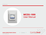
Daily Procedures 2015 Power*Suite Daily Office Procedures Program Activation 1.) Double click on the Power*Log, Power*Curve or Power*Core Acknowledge the Security Information window by clicking on the initiate the program and activate a Connect Database window. Icons on your desktop. button. This will Connecting to a Database… 2.) Highlight the database you wish to connect to by clicking on it once. The default after loading the PowerSuite software is the PGEOLOGY 2015 METRIC (Microsoft Access Driver [*.mdb]). 3.) The user can simply Tab to the Password field or Type in your User ID. The default User ID is “pgeology” and is displayed as the default in this field. 4.) Type in your Password. (The default Password is "pgeology"). button to complete the connection or Press the Enter key on your 5.) Click on the keypad. This will activate the Open Log window. Note: To change the password refer to the Power*Suite Database Management Tool. 6.) Click on the button to close this window. Then, you can import the new data files. Note: If you have received our .exp files via email, you must first detach or save these files somewhere on your hard drive or network drive. Daily Procedures 2015, page 1 Daily Procedures 2015 Data Import (refer to page 78 in the User Manual) (On-line help press F1 key on keypad) If the data file *.exp is attached to an email the user must first detach the file or save it to a place so that it can be found within your file format structure to import. 1.) Select Import, under File Menu, and then select Log / Well from the sub-menu. Or, you can use the Import button on the Toolbar. This will activate the Import window 1.) Click on the button. This will activate the Import from window. 2.) Select the appropriate drives and or directories as well as files you wish to import by highlighting the button. This will place the selected files into the Power*Log file name and clicking the Data Transfer: Import V 2015 Window. Repeat this step as many times as necessary. N.B. Any of our exported files will have an *.exp extension. If the files are corrupted a message will tell you so. Some files may be encrypted and you will have to decrypt the files using the appropriate decryption password using all upper case letters. 3.) Highlight the files you wish to import by clicking on the file name. button. This will activate a message 4.) Once the files are selected (highlighted) click on the box asking, “Do you really want to import the highlighted files?” button to begin the file importation. When the files have been imported you 5.) Click on the will be presented with a message window stating “Data has been imported successfully.” N.B. If an exported file had the option of an entire well activated a message box will appear asking the user “About to IMPORT ENTIRE WELL data. All information associated with this well in the database will be overwritten. Continue?” Click on the data you have or click on the have. 6.) Click on the 7.) Click on the button if the file is newer than the button if the file is older than the information you already button to acknowledge this message box. button to put you back into the main Power*Suite window. Daily Procedures 2015, page 2 Daily Procedures 2015 Open Well / Log (refer to page 26 in the User Manual) (On-line help press F1 key on keypad) Open Log 1.) To view a log presentation of the wells’ data you must first open the log. Click on the button or select Open, under the File menu pull down, to activate the Open Log window shown below: 2.) In the Well List locate the well you wish to open either by querying or scrolling through the Well List portion of the window and Click on the Well Name so it becomes highlighted, and the logs available for that well will appear in the Log List portion of the window. 3.) In the Log List Click on the log name you want to open. It will become highlighted. button and the selected log will open accordingly. Please keep in mind that 4.) Click on the Power*Log / Core & Curve™ allows you to have multiple logs open at once. The Recent Logs portion of the window indicates the last 10 logs / wells opened. You may wish to select one of these rather than looking through the well list. Also if you are reopening the last well used it is already highlighted in the Recent Logs list and can be reopened easily by clicking on the button or by depressing your enter key on your keypad. Note: Logs with the letter "V" in front of their names are Vertical logs, and can only be used within Power*Log or Power*Core™. Likewise, Logs with the letter "H" in front of their names are Horizontal logs, and can only be used within Power*Curve™. N.B. If a well / log is already open and you have imported an updated file, the user must click on Option on the Menu Bar and click on Refresh Data and the well / log will be updated with the new updated database entries. To scroll click on the up/down arrows to scroll ¼ page, the space between the thumb and the arrow for a page up/down, or if the print section has been completed pull the thumb up or down to go to the start or end of a log. If your mouse has a roller wheel you can use that as well to scroll the log. To go directly to a depth on the log, type a number in the go to depth box on the toolbar and then tab out of the box to place that depth at the top of the log. To change screen scales either select a scale from the pull down menu on the toolbar or type a scale between 1:1 and 1:5000 to view the log in a different scale. The screen default scale is 1:240. Daily Procedures 2015, page 3 Daily Procedures 2015 Striplog Printing (refer to page 126 the User Manual) (On-line help press F1 key on keypad) Print Log to a Printer Device Driver Prints all or part of your log/well along with the Title page, location map, legends, survey views, individualized cores and formation tops on a continuous or single sheet basis 1. Under the File menu selection, click on Print Log or click on the activate the Print Log window shown below: Print button on the Toolbar to Note: The Title bar and all depths associated with the Print Log window are defaulted to the Depth View that Power*Log is in at the time of the activation of the Print Log window. 2. Select the appropriate paper orientation from this drop box field and the Title Page, Legend, and Formation Tops will automatically conform to the selected orientation. There are four (6) types of paper orientation to choose from: letter (8.5”x11”) portrait or landscape, legal (8.5”x14”)portrait or landscape, tabloid (11”x15”) portrait or landscape settings Note: The letter, legal or tabloid landscape or portrait settings selected from within the Print Log window will NOT override the paper orientation settings selected in the printer's Properties window. Therefore, you must also modify the paper orientation settings in your printer's Properties window to letter or legal landscape. 3. Activate this check box Daily Procedures 2015, page 4 , if you wish to printout a full Version of the Title Page. Daily Procedures 2015 4. If you are printing the Striplog Title page and you are in Alberta the AER format should be selected. N.B. This format changes our UWI printout from 100121605812W500 to 00/12-16-058-12W5/0 only on the Striplog Title page. All other UWI formats remain the same. 5. Activate this check box , if you wish to printout an abbreviated version of the Core Log Title Page. Activate this check box , if you wish to printout an abbreviated version of the Core 6. Log alternate title Page. Activate this check box , if you wish to printout an abbreviated version of the 7. Sample Log Title Page. 8. Activate this check box , if you wish to printout a logo, and then select a logo from the Logo drop box field. Note: The logo file format must be a bitmap image file (*.bmp) if you want a logo printed out on the title page. Also, it is recommended that the bitmap image should be a square image, because Power*Suite will shrink or expand the image to fit the logo space on the Title Page. This bitmap must be placed in the Powersuite_2015\logo directory for the application to find it. 9. Activate this check box , if you wish to printout a location map following the title page, and then the user select a location map from your computers and finding the file you want to print out as a location map. drives by clicking on the Note: The Location map file format must be a bitmap image file (*.bmp) if you want a location map to be printed out. Also, the bitmap image must be a square image, because Power*Suite will shrink or expand the image to fit the location map space following the Title Page. This bitmap can be placed anywhere as the file location is saved within the Power*Suite ini file. 10. Type any pertinent comments into the Title Page Remarks field and they will be displayed accordingly on the Strip Log Title Page only. Activate this check box , if you wish to have the plan view (view of the well 11. Survey views bore from surface) printed out in the striplog header as captured in the Survey View application. Activate this check box , if you wish to have the user defined view (view of 12. Survey views the well bore as manipulated by the user) printed out in the striplog header as captured in the Survey View application. Activate this check box , if you wish to have the azimuth view (view of the 13. Survey views well bore along the target azimuth) printed out in the striplog header as captured in the Survey View application. Activate this check box , if you wish to have the cross section view (view of 14. Survey views the well bore at right angles to the target azimuth) printed out in the striplog header as captured in the Survey View application. Activate this check box , if you wish to have all the views printed out in the 15. Survey views striplog header as captured in the Survey View application. Activate this check box , if you wish to have our entire legend printed out. 16. 17. Activate this check box , if you wish to have the legend reflect only the symbols printed on the log or core portions of the printed intervals defined in the log and core portions of the print log window. In the Log portion of the Print Log window Select or type in the Scale for the main log to be printed out at, in the Scale drop box 18. field. Note: If you see 2” or some other inch related printing scale and you want to see a ratio type scale Change the System Options under the Options pull down menu and activate the Display Tab and Activate this check box beside Use Metric Style Scales. The Well Section interval is derived from the Top and Base Depth values entered into the Print Sections window under the Edit pull down menu. (see Print Sections). The Lithology Section interval is derived from what has been drawn into the interpretive lithology track of the well that is being printed. Daily Procedures 2015, page 5 Daily Procedures 2015 19. 20. Activate this check box to have the track headers printed out with the main log. Activate this check box to have the track footers printed out with the main log. Activate this check box to have the core accessories 21. printed out on the main log. 22. Highlight the main log printing options in the selection box. The user can select either None, User-defined Interval (requires that you manually enter the desired print interval depths), Today Section, Well Section, or Lithology Section. Note: Today Section interval is derived from the From and To Depth values entered into the Today’s Section portion of the Power*Log Data Transfer: Export window. The Well Section interval is derived from the Top and Base Depth values entered into the Print Sections window under the Edit pull down menu. (see Print Sections). The Lithology Section interval is derived from what has been drawn into the interpretive lithology track of the well that is being printed. 23. If user defined interval is chosen the user can select which depth type, either measured depth, true vertical depth or subsea level depth from the depth measurement drop box. The user must also type in the depth interval to be printed. Note: The log itself must be displayed in whatever depth view you wish to print before you activate the print log window. To change the log to the desired format, refer to depth view under the view pull down menu. In the Cores portion of the Print Log Window 24. If you are printing out a Core log on the tail of the striplog, select the Cores you wish to print by highlighting them. 25. Select or type in the Scale for the core log to be printed out at in the Scale drop box field. Activate this check box to have the track headers printed out with the core log. 26. Activate this check box to have the track footers printed out with the core log. 27. Note: A separate Header Information Box is automatically printed out with every Core and includes the Core Scale, Core Date, Core Number, Cored Interval, Amount Cut, Amount Recovered, and Percentage. **A value must be entered into the Core Scale field in order to printout anything. ** 28. Activate this check box if you wish to printout Formation Tops and the Formation Tops will be included on a separate page at the end of the log printout. The page margin field is available, primarily, when you are printing to Adobe Acrobat writer. When a numerical value in inches is typed into this field it will initiate a top and left margin for the templates (Title Page, Legend and Formation Tops) as well as a left margin for the main log. Activate this check box if you are printing on single sheets. This will force the printer to include an additional 1/4 inch of the log at the top and bottom of each page, so that you can cut-andpaste pages manually, if you so desire. Default Activating the default radio button forces Power*Log / Core & Curve to use a raster or bitmap graphic printing method. This printing method is generally used with Laser printers but not exclusively so. Meta File Activating the Meta File radio button forces Power*Log / Core & Curve to use the meta file technology printing method. This printing method was developed for the newer models of printers on the market today as well as using the Adobe Acrobat Distiller or pdf printing technology. Auto Activating the Auto radio button forces Power*Log / Core & Curve to use the settings from the printer driver to printout the log. Color Activating the Color radio button forces Power*Log / Core & Curve to override the printer driver settings and consequently Power*Log / Core & Curve assumes that you are using a color printer. Daily Procedures 2015, page 6 Daily Procedures 2015 Mono Activating the Mono radio button forces Power*Log / Core & Curve to override the printer driver settings and consequently Power*Log / Core & Curve assumes that you are using a monochrome (black and white) printer. button to activate the Print Setup window and confirm that the correct printer 29. Click on the settings are in effect. Note: If you are printing out logs in color, you must activate the Diffusion or Error Diffusion option normally found under Graphics in the Properties window for most printers. 30. Interval per page field indicates how many meters of log will fit on a page of selected paper size and orientation selected in the setup as well as what log scale you are printing at. This will help indicate to the user how many pages will be required by the print job. Activate this check box if the user wishes to have a blank page before the logs starts. 31. This could be useful if utilizing continuous paper when you want the title page oriented on the correct side of the pre folded paper. 32. When you are ready to print your log, click on the button. Note: If you do exit from the Print Log window, you will be asked if you wish to save the print settings. If you click on Yes, the program will remember every setting that you made to the Print Log window and then will default to those settings the next time you enter the Print Log window Daily Procedures 2015, page 7 Daily Procedures 2015 Print to TIFF (file format) (refer to page 129 in the User Manual) (On-line help press F1 key on keypad) Prints all or part of your log/well along with the Title page, location map, legends, survey views, individualized cores and formation tops on a continuous basis in a tiff file format. 1. Under the File menu selection, click on Print to TIFF or click on the Toolbar to activate the Print to TIFF window shown below: Print to TIFF button on the Note: The depth views associated with the Print TIFF window are defaulted to the Depth View that Power*Log / Curve / Core is in at the time of the activation of the Print to TIFF window. Select the appropriate paper orientation from this drop box field and the Title Page, Legend, and Formation Tops will automatically conform to the selected orientation. There are four (6) types of paper orientation to choose from: letter (8.5”x11”) portrait or landscape, legal (8.5”x14”)portrait or landscape, tabloid (11”x15”) portrait or landscape settings. Activate this check box , if you wish to printout a Title Page. 3. 4. The Type (Title Page) drop box displayed on the right allow you to pick the appropriate title page format to print. The standard selection prints out our full blown title page with most of the Wells data. You can also select our abbreviated title pages that handle core and borehole logs If you are printing the Standard Title page and you are in Alberta the AER format should 5. be selected. 2. N.B. This format changes our UWI printout from 100121605812W500 to 00/12-16-058-12W5/0 only on the Striplog Title page. All other UWI formats (DLS and NAME) remain the same. 6. Activate this check box , if you wish to printout a logo, and then select a logo from the Logo drop box field. Note: The logo file format must be a bitmap image file (*.bmp) if you want a logo printed out on the title page. Also, it is recommended that the bitmap image should be a square image, because Power*Suite Daily Procedures 2015, page 8 Daily Procedures 2015 will shrink or expand the image to fit the logo space on the Title Page. This bitmap must be placed in the Powersuite_2015\logo directory for the application to find it. 7. Type any pertinent comments into the Title Page Remarks field and they will be displayed accordingly on the Strip Log Title Page only. Activate this check box , if you wish to printout a 8. location map following the title page, and then the user select a location map from your computers drives by clicking on the and finding the file you want to print out as a location map. Note: The location map file format must be a bitmap image file (*.bmp) if you want a location map to be printed out. Also, the bitmap image must be a square image, because Power*Suite will shrink or expand the image to fit the location map space following the Title Page. This bitmap can be placed anywhere as the file location is saved within the Power*Suite ini file. 9. Survey views Activate this check box , if you wish to have the plan view (view of the well bore from surface) printed out in the striplog header as captured in the Survey View application. Activate this check box , if you wish to have the user defined view (view of 10. Survey views the well bore as manipulated by the user) printed out in the striplog header as captured in the Survey View application. Activate this check box , if you wish to have the azimuth view (view of the 11. Survey views well bore along the target azimuth) printed out in the striplog header as captured in the Survey View application. Activate this check box , if you wish to have the cross section view (view 12. Survey views of the well bore at right angles to the target azimuth) printed out in the striplog header as captured in the Survey View application. Activate this check box , if you wish to have all the views printed out in the 13. Survey views striplog header as captured in the Survey View application. Activate this check box , if you wish to have our entire legend printed out. 14. 15. Activate this check box , if you wish to have the legend reflect only the symbols printed on the log or core portions of the printed intervals defined in the log and core portions of the print log window. In the Log portion of the Print Log window Select or type in the Scale for the main log to be printed out at, in the Scale drop box 16. field. Note: If you see 2” or some other inch related printing scale and you want to see a ratio type scale Change the System Options under the Options pull down menu and activate the Display Tab and Activate this check box beside Use Metric Style Scales. The Well Section interval is derived from the Top and Base Depth values entered into the Print Sections window under the Edit pull down menu. (see Print Sections). The Lithology Section interval is derived from what has been drawn into the interpretive lithology track of the well that is being printed. 17. Activate this check box to have the track headers /footers printed out with the main log. Activate this check box to have the core accessories printed out on the main log. 19. Highlight the log printing options in the selection box. The user can select either None, User-defined Interval (requires that you manually enter the desired print interval depths), Today Section, Well Section, or Lithology Section. Note: Today Section interval is derived from the From and To Depth values entered into the Today’s Section portion of the Power*Log Data Transfer: Export window. The Well Section interval is derived from the Top and Base Depth values entered into the Print Sections window under the Edit pull down menu. (see Print Sections). 18. Daily Procedures 2015, page 9 Daily Procedures 2015 The Lithology Section interval is derived from what has been drawn into the interpretive lithology track of the well that is being printed. 20. If user defined interval is chosen the user can select which depth type, either measured depth, true vertical depth or subsea level depth from the depth measurement drop box. The user must also type in the depth interval to be printed. Note: The log itself must be displayed in whatever depth view you wish to print before you activate the print log window. To change the log to the desired format, refer to depth view under the view pull down menu. In the Cores portion of the Print Log Window 21. If you are printing out a Core log on the tail of the striplog, select the Cores you wish to print by highlighting them. Select or type in the Scale for the core log to be printed out at in the Scale drop box 22. field. Activate this check box to have the track headers / footers printed out with the 23. core log. Note: A separate Header Information Box is automatically printed out with every Core and includes the Core Scale, Core Date, Core Number, Cored Interval, Amount Cut, Amount Recovered, and Percentage. **A value must be entered into the Core Scale field in order to printout anything. ** 24. Activate this check box if you wish to printout Formation Tops and the Formation Tops will be included on a separate page at the end of the log printout. The page margin field is available, primarily, when you are printing to Adobe Acrobat writer. This is not necessary for printing to tiff file format 25. When you are ready to print your log, click on the button. 26. This will activate a message box indicating the size of your printout. Click on the button. 27. This will activate a file name window which should be filled in with your file name and location to where you can locate it for further reference. Note: If you do exit from the Print to TIFF window, you will be asked if you wish to save the print settings. If you click on Yes, the program will remember every setting that you made to the Print to TIFF window and then will default to those settings the next time you enter the Print to TIFF window Daily Procedures 2015, page 10 Daily Procedures 2015 Print Morning Reports Crystal Format (refer to page 132 in the User Manual) (On-line help press F1 key on keypad) 1. Under the File menu selection, click on Print Morning Report or click on the Morning Report button on the Toolbar to activate the Print Morning Report window shown below: Printing Morning Reports… 1. Select the printing destination from the Output field (in the upper left corner of the Morning Report window), drop box arrow: Printer, Preview, or Disk File. The Preview option allows you to see what your report looks like before it is printed. Note: The Preview option will only preview one report at a time. Accordingly, when you wish to preview a specific report, please be sure that no other reports are selected / highlighted. 2. If printing to a Disk File (on your hard drive or to a flash drive), select the file format from the Disk File Format field drop box arrow. If you want to print the report to MS Word then you should use the Print to Word Option under the File pull down menu. button and then 3. You can select a different well other than the default well by clicking on the double click on the desired Well from the ensuing Well List window. Please note that you may select numerous Wells, from the Well List window, for printing. Once you have selected your Well(s), you will then be returned to the Morning Report window. *Only the selected/highlighted well and their selected/highlighted reports will be printed. * To highlight a Well, click on it once. To remove a Well from the Well List field, highlight the Well and click on the button. To remove all of the Wells from the Well List field, click on the button. Note that these buttons will not remove any of the Wells from the database. These buttons will only remove the Wells from the list of Wells currently available for printing. 4. Highlight the appropriate Morning Report (listed by Date), and the related reports that you wish to print. You may click on the button to print all of the Morning Reports from that Well. Conversely, to deactivate all of the Morning Reports, simply click on the 5. Click on the button. button to activate the Report Format window. Daily Procedures 2015, page 11 Daily Procedures 2015 Using the Format field drop down arrow, click on the style of Report Format that you wish to use. Then, button, when you are finished. click on the Note: TV Morning Report Formats include the Daily and Accumulative Costs and the PS Morning Report Formats do not. 6. Click on the button and then select the 8.5” x 11” Portrait paper size. 7. Click on the button. 8. If you have selected the Disk file option from the destination out put drop box you will be prompted with a Save As window. Type in the in a five (5) character (or less) filename and click on the button. Power*Log / Core & Curve ™ will then attach an extra two (2) characters to the end of your filename to create a seven (7) character filename--preceding the standard three (3) character file extension. The two (2) characters added by Power*Log / Core & Curve ™ on to the end of the five (5) characters you have typed in are used as a reference by Power*Log / Core & Curve ™ to distinguish which reports are to be included in the files you are creating. Finally, the standard three (3) character file extension following the dot or period, will be selected according to the file format you selected in the Disk File Format field, e.g. MS Word documents will use the .DOC file extension. For example, if the five (5) characters you chose for a file name were "Trial" and you chose to print all Morning Reports with multiple days (and your Disk File Format was ASCII), you would end up with the following six (6) files: TRIALLT.txt TRIALTG.txt TRIALGS. txt TRIALFM. txt TRIALSC. txt TRIALSG. txt Summary and Lithology Report Total Gas Summary Report Gas Chromatography Summary Report Formation Report Formation, Lithology Summary and Chromatography Formation, Lithology Summary and Total Gas Note: You can then use a word processor, like MS Word, to access these files. Formation Tops are automatically created in a Morning Report, if the depths specified fall within the range of the Morning Reports, two days prior to the day of printing. In order to have the Formation Tops printed, you must enter data into at least two Morning Report Date and Depth fields, prior to printing. Power*Log/Curve™ searches for the Depth information to locate the Formation Tops it should include for the Date selected. Note: When you exit from the Print Morning Report window, you will be asked if you want to save the print configuration. If you click on Yes, the program will remember every setting that you made to the window and will default to these settings the next time you enter the window. Daily Procedures 2015, page 12 Daily Procedures 2015 Print Well End Reports (refer to page 133 in the User Manual) (On-line help press F1 key on keypad) Crystal Format Well End Report Under the File menu selection, select Print Well End Report or click on the button on the Toolbar to activate the Print Well End Report window shown below. Printing a Well End Report… 1. Select the printing destination from the Output field (in the upper left corner of the Well End Report window), drop box arrow: Printer, Preview, or Disk File. The Preview option allows you to see what your report looks like before it is printed. Note, however, that the Preview option will only preview one report at a time. Accordingly, when you wish to preview a specific report, please be sure that no other reports are selected / highlighted. Note: To select or configure a specific printer, click on the button. 2. If printing to a Disk File (on your hard drive or to a flash drive), select the file format from the Disk File Format field drop box arrow. 3. If the default well is not the well you want to print from then you can select a Well for printing by button and then double click on the desired Well from the ensuing Well List clicking on the window. Please note that you may select numerous Wells, from the Well List window, for printing. Once you have selected your Well(s), you will then be returned to the Well End Report window Note: Only the selected / highlighted wells and their selected/highlighted reports will be printed** To highlight a Well, click on it. To remove a Well from the Well List field, highlight the Well and then click on the button. To remove all Wells from the Well List field, click on the button. Note that these buttons will not remove any of the Wells from the database. These buttons will only remove the Wells from the list of Wells currently available for printing. 4. Select/highlight and/or deactivate any of the reports in the Reports field by clicking on them once. To select/highlight all of the reports, click on the button. To deactivate all of the reports, click on the button. Daily Procedures 2015, page 13 Daily Procedures 2015 Note: Daily Drilling Summary Report Update… If your Daily Drilling Summary Report is not up-todate or is missing Progress and Average P.R. (Penetration Rate) data you must select Print Morning Report under File on the Selection Bar. This will activate the Print Morning Report window, then exit from the Print Morning Report window (without performing any tasks), and return to the Well End Report window to printout your newly updated Daily Drilling Summary Report. 5. If you are printing Sample Descriptions, you may print all or a portion of the descriptions. To print all of the intervals, activate the All check box . To print specific intervals only, enter the start and end points, i.e. Measured Depth intervals, in the appropriate interval fields and then deactivate the All check box . 6. If you are printing the Title Page, click on the button and fill in the required information. This information is only used on the Title Page of the report. Note: In order to have the Formation Evaluation Report printed out, there are two fields that must be filled in on your Well Formation window. These are the Boundary Type field and the Period field. If these two fields are left blank, the Formation Evaluation Report for that Formation will not be printed out. 7. Click on the button to activate the Report Format window shown below: 8. Using the Format field drop down arrow, click on the style of Report Format that you wish to use. Then, click on the button, when you are finished. Note: Report Formats are useful when you are printing reports for various clients, who prefer specific Report Formats. The formats store reports in their own directories. 9. If you only want to printout a Table of Contents, activate the Table of Contents Only check box and then make sure that the reports you want to include on the Table of Contents are selected/highlighted. Note: You can start printing at any page by typing the page number in the Start Printing at Page # field. 10. The user has a choice of paginating by section number (18 – 1, 2, 3 etc.), or paginating by section name (Sample Description – 1, 2, 3 etc.). The Table of Contents will reflect these choices if you print the table of Contents with all the reports at the time of printing. 11. The user also now has the choice of paginating the reports continuously pages 1 - infinity, and with this option you can also use the start printing at page # option. 12. Click on the button and then select the 8.5” x 11” Portrait paper size. 13. Click on the button. 14. If you are printing to a disk file you will then be prompted with a Save As window will pop up. Type in a filename and click on the button. Power*Log / Core & Curve™ will then attach an extra two (2) characters to the end of your filename--preceding the standard three (3) character file extension. The two (2) characters added by Power*Suite™ on to the end of the filename that you have typed in are used as a reference by Power*Suite™ to distinguish which reports are to be included in the file you are creating. Finally, the standard three (3) character file extension following Daily Procedures 2015, page 14 Daily Procedures 2015 the dot or period, will be selected according to the file format you selected in the Disk File Format field, e.g. Ascii documents will use the *.txt file extension. Note: If you want to print to MS Word then please select the Print to Word option under the File pull down menu. The Survey views cannot be printed to a disk file or to preview. They can only be printed to a directly to a printer or to a pdf file format. Below is a list of the file names that Power*Log / Core & Curve™ uses to identify different reports for the pdf printer selection. For the file names below you will see the Crystal Reports - before every file name: Report Name Title Page Survey Plan View Survey Azimuth View Survey Multi View Daily Drilling Summary Bit Record Summary (IADC) Bit Record Summary Core Descriptions Logging Reports Directional Surveys Deviation Survey Points Mud Data Formation Tops Sample Descriptions Sidewall Cores MDT Run Table of Contents File Output Name wendttle.pdf Survey Plan View.pdf Survey Azimuth View.pdf Survey Multi View.pdf drillsum.pdf bittable.pdf bitrec.pdf fcordsc.pdf logging.pdf survey.pdf survptss.pdf fluid.pdf tops.pdf samptext.pdf sidewall.pdf MDT.pdf wendtoc.pdf Report Name Well Abstract Survey Cross Section Survey User Defined Well Summary Casing Strings Bit Record Summary (TBG) Core Plugs Core Description / Report Core Header Test Reports Directional Survey Points Master Survey Group Abandonment Plugs Work Schedule Formation Evaluation Sample Description / Tops Geology Dictionary File Output Name abstract.pdf Survey Cross Section.pdf Survey User Defined.pdf gwellsum.pdf casing.pdf bittabdb.pdf corplug.pdf fcortext.pdf test.pdf survpnts.pdf msurvpnt.pdf plug.pdf worksch.pdf formaton.pdf fsmptext.pdf geodict.pdf **The button, in the upper right corner of the Print Well End Report window, will take you to the Print Morning Report window. ** Note: Upon closing the Print Well End Report window, you will be asked if you want to save the print configuration. If you click on button, the program will remember every setting that you made to the window and will default to these settings the next time you enter the Print Well End Report window. Print to Preview 1. In the Print Well End Report or Print Morning Report windows, select "Preview" from the Output field drop box in the upper left corner of the given window. 2. Select the report you wish to preview by clicking on it and the report will then be highlighted. button and you will be launched into the Print Preview mode, where you 3. Click on the will see your report displayed on screen exactly as it will look when it is printed. Note: You can only preview one report at a time. If numerous reports are highlighted, only the first one on the list will be previewed. Also, you can only printout one report at a time from within the preview mode. When in the Preview mode, you have some tools available to you at the bottom of the screen. This is the Zoom text field. It allows you to zoom in and out of the report to display it in different sizes. This is the Print button. Click on this button to print your previewed report to paper. This is the Export button. It lets you reproduce the report to another file format. To exit from the Preview mode without printing, simply click on the Close button at the bottom of the Print Preview window. You are able to view multiple page reports by using the navigational tools(similar to the Database Navigational Tools), at the lower left side of the Print Preview screen: First Page Last Page One Page Forward One Page Backward Daily Procedures 2015, page 15 Daily Procedures 2015 Print “Well End and AM” Reports to Word Format This printing method will facilitate the printing of the Geological reports to MS Word format. They are formatted identical to the Crystal Reports. This new generation of reports should be easily reformatted after the printing process to customized to other formatting requirements. 1. Click on Print Reports to Word, under the File menu selection, to activate the Print Reports to Word window shown below. The user can also click on the Shortcut button located on the toolbar. Overview of Well End Reports Tab Window Prepared For Fields are to be filled in for the Title page report. Type in the Company Name you are working for in the company field and the Person’s name you are working for or is receiving the reports in the Name field Prepared By Fields are to be filled in for the Title page report as well. Type in your Company Name in the company field and your name in the Name field This field defaults to the well that is open when you enter into this application. The user can utilize the drop arrow to pick any well they have in their database. The Depth Range fields are available to print a portion or depth interval of the Sample or Core descriptions as well as Devon Malibu Format Moring Reports. Leave these fields blank to print them all. Activate this check box if you want to include the Formation tops in the Sample or Core Descriptions report. This field gives the user to identify which well end reports they would like to print and they can also identify multiple reports to print at once. Click on the report name to activate or highlight the report to be printed and Click again to deactivate the report. Scroll through the list to identify which reports you wish to print. Activate this check box if you wish to print multiple reports to a single file. Or conversely deactivate this check box if you want multiple files created. This button will highlight all the reports and you can activate the reports you do not wish to print. This button will deselect all the reports and you can activate the reports you wish to print. This button will activate the printing process and create either single or multiple files. The documents created will be Document 1 Document 2 etc. Daily Procedures 2015, page 16 Daily Procedures 2015 How to Print Well End Reports to MSWord. (refer to page 137 in the User Manual) (On-line help press F1 key on keypad) 1. Click on Print Report to Word, under the File menu selection, to activate the Print Reports to button located on the toolbar. Word window. The user can also click on the shortcut 2. Choose the well you wish to create a report for from the selection box if the default well is not the one you want to print. 3. Highlight the reports you wish to print in the Reports field by clicking on them once. To button. To deactivate all of the reports, click select/highlight all of the reports, click on the on the button. . If you are printing sample or core Descriptions select if you wish to print tops or all the descriptions. button to create the reports. This will activate your copy of MS Word 4. Click on the application and you can view, customize and save these reports. Overview of Morning Reports Tab Window This field defaults to the well that is open when you enter into this application. The user can utilize the drop arrow to pick any well they have in their database. The date field gives the user the ability to identify which Morning reports date they would like to print. The user has the ability to print one or more report dates. Select or deselect them by clicking on them once. Daily Procedures 2015, page 17 Daily Procedures 2015 This identifies which portion of the report they would like to print. The choices will be activated with a check box. This information is entered into the Morning reports located under the Reports pull down menu in Power*Log / Core or Curve. This gives the user the ability to pick and choose which of the Well End reports they would like to include with the printed am report. They include Bit records Casing Formations and Surveys. All these records default to the depth interval from the previous morning report but can be modified by the user. to activate the Set Depth Ranges window so the user Click on the can decide what ranges of well end report data to include with the AM report printing. The default is the depth from the previous Am report and the one you have selected to print. Activate this check box if you wish to print multiple report dates to a single file. Or conversely deactivate this check box if you want multiple files created. This button will highlight all the am report dates. This button will deselect all the am report dates. This button will activate the printing process and create either single or multiple files. The documents created will be Document 1 Document 2 etc. How to Print AM Reports to MSWord. (refer to page 139 in the User Manual) (On-line help press F1 key on keypad) 1. Click on Print Report to Word, under the File menu selection, to activate the Print Reports to Word window. The user can also click on the shortcut button located on the toolbar. 2. Click on the Morning Reports tab to activate that portion of the window. 3. Choose the well you wish to create a report for from the selection box if the default well is not the one you want to print. 4. Highlight the report dates you wish to print in the Dates field by clicking on them once. To select/highlight all of the reports, click on the button. To deactivate all of the reports, button. click on the 5. Select the report options from the appropriate check boxes. 6. Select from the Single Report Options which data from the well end reports you would like to include in this printed AM report. 7. If you have selected some Well End report data to be included with the AM report printing and you would like to change the default depths to search for a different interval of data then you would Click on the to activate the window and change the depths accordingly. Daily Procedures 2015, page 18 button Daily Procedures 2015 8. Click on the button to return to the main window. 9. Click on the button to print the AM report to word format. This will activate your copy of MS Word application and you can view, customize and save these reports. Export LAS Data (refer to page 114 in the User Manual) (On-line help press F1 key on keypad) The Power*Suite LAS Export Utility program can be accessed through the Power*Suite folder and facilitates the export of Power*Suite curve data into an LAS File. 1. Under the File menu selection, click on Export, click on LAS. You can also select the the Export toolbar. This will activate the LAS Export window. Icon on button. This will activate a list of all the wells in your Database. 2. Click on the 3. Select the well you wish to export your LAS Curve data for by clicking on the well name and then clicking on the button or by double click on the well. You should now see your well button. Also, you should see a list of curves in the Curve List name in the field beside the field. An example of this is shown on the next page. 4. Click on the button and type in a file name and path for that file in the window. Click on the button when you have done. 5. The user can export Version 2 (checked) or Version 3 file format (unchecked). 6. Select the Curves you wish to create a file for by click on the curve name in the Curve name field or button to select all the curves. by clicking on the 7. Select the step type you wish to use for the export. Extrapolate will give you the best incremental data utilizing a constant step extrapolating the data to replicate this constant step. The Curve depths selection will merge the curves (if more than one curve is selected) and will export the data as it has been collected into the database. Daily Procedures 2015, page 19 Daily Procedures 2015 8. Type in an appropriate step (depth increment) or utilize the default 1 m depth increment. 9. Optional Type in an interval in the From and To fields and deselect the Extract Interval All check box if you wish to export just a portion of the curve data. 10. Optional If the user wishes to Change Null Value. a. Click on the button. This will activate a Null Value window. b. Type in another Null value if the default null value of –999.25 is not what you want for a null value and then click on the button. 11. Optional Select the reverse direction check box if you want the data in descending order. 12. Optional Select the other depth units other than (MD) Measured Depth (default) to be included with your LAS file. Click on one or both of the check boxes as (TVD) True Vertical Depth or (SSL) Subsea Level. beside the other such selections button. This will activate a LAS file generation window indicating which 13. Click on the curves are being exported. Then the process amalgamates all the curve data into a single LAS File. When the file generation has been completed a System Message will be generated. Note: There may be a message box encountered during this process indicating some of the curves selected have no data. You will have a choice of not including these curves in the LAS Export file. 14. Once the File has been created acknowledge the ensuing message by clicking on the button. Daily Procedures 2015, page 20 Daily Procedures 2015 Export Well Data as an LAS File (refer to page 123 in the User Manual) (On-line help press F1 key on keypad) This utility exports all your well data including curve data from your database in LAS Version 3 format. Exporting LAS Well Data Click on Export under File to activate the pop-out menu and then select Well as LAS. You can also select the Icon on the Export toolbar. This will activate the Export Directional Surveys window. 1. Click on the Data Types you want in the LAS File. The data types highlighted will be included. You can turn on / off the highlight by clicking on the data types. 2. The button will select all the data categories and the data categories. 3. Click on the button will deselect all the button. This will activate a Save LAS File Name window. 4. Type in a file name and select the drive and directory you wish the survey to be exported to. Then, click on the button. Your file name will be created in the folder you directed it to. Daily Procedures 2015, page 21 Daily Procedures 2015 Export ASCII Well Data (refer to page 106 in the User Manual) (On-line help press F1 key on keypad) This utility will create ASCII files, or comma delimited files of certain lithology data types (other than curves) for any well in the database. The utility can create a single file of the chosen data categories or multiple files with the same file name entered and their own file extensions. The file types and file extensions are listed at the end of this section. 1. The first step in creating an ASCII or comma delimited file(s) is to select Export from the File menu selection. Then, select ASCII Lithology Export from the ensuing pop-out menu. Then, select the file format you wish to export the data into. We have tailored our ASCII files to be compatible with Landmark. This will activate the ASCII Lithology Export window. 2. The user can select the file format for the ASCII Lithology Export by clicking on the Select Output format arrow and selecting the file from the output list. This will place your selection in the file format field. button to activate the Well list window. This will activate the Well List window. 3. Click on the 4. Select the well by double clicking on the Well Name / UWI that you wish to make a ASCII Lithology Export for. The user can also click on the Well Name / UWI to highlight it and then click on the button. This selection will then be populated in the Well field in the Log Dump window. Daily Procedures 2015, page 22 Daily Procedures 2015 5. Click on the button and this will activate the Choose filename window. 6. Type in a file name and select the drive and directory you wish the file(s) to be exported to. Then, click on the button. This will fill in the Choose file field in the Log Dump window with the drive, directory and file name. 7. Select the data types you wish to populate your ASCII lithology export file(s) with by clicking on them once to make them highlighted. The user can deselect the data types by clicking on them again. Also, the user can click on the button to select all the data categories or click on the button to clear all your selections. 8. If you want only one data type in each file created click on the Save as multiple files check box . If deselected or unchecked the dump will populate a single file. N.B. If the user wishes to export all the wells in your database at one time you must first create a folder to accept the ASCII file dump and then click on the button. 9. Click on the button to initiate the export. This will activate a System Message. 10. Click on the button to acknowledge the message. 11. Click on the button to escape the Log Dump window or repeat steps 3-6 to create another set of ASCII Data Files. Daily Procedures 2015, page 23