1
User Manual
VX4330
120-Channel Relay Multiplexer Module
070-9178-01
This document applies for firmware version 1.00
and above.
Copyright Tektronix, Inc. 1995. All rights reserved. Licensed software products are owned by Tektronix or its suppliers
and are protected by United States copyright laws and international treaty provisions.
Use, duplication, or disclosure by the Government is subject to restrictions as set forth in subparagraph (c)(1)(ii) of the
Rights in Technical Data and Computer Software clause at DFARS 252.227-7013, or subparagraphs (c)(1) and (2) of the
Commercial Computer Software – Restricted Rights clause at FAR 52.227-19, as applicable.
Tektronix products are covered by U.S. and foreign patents, issued and pending. Information in this publication supercedes
that in all previously published material. Specifications and price change privileges reserved.
Printed in the U.S.A.
Tektronix, Inc., P.O. Box 1000, Wilsonville, OR 97070–1000
TEKTRONIX and TEK are registered trademarks of Tektronix, Inc.
VXIbus is a trademark of the VXI Consortium.
SurePath and Intelliframe are registered trademarks of Tektronix, Inc.
WARRANTY
Tektronix warrants that this product will be free from defects in materials and workmanship for a period of three (3) years
from the date of shipment. If any such product proves defective during this warranty period, Tektronix, at its option, either
will repair the defective product without charge for parts and labor, or will provide a replacement in exchange for the
defective product.
In order to obtain service under this warranty, Customer must notify Tektronix of the defect before the expiration of the
warranty period and make suitable arrangements for the performance of service. Customer shall be responsible for
packaging and shipping the defective product to the service center designated by Tektronix, with shipping charges prepaid.
Tektronix shall pay for the return of the product to Customer if the shipment is to a location within the country in which the
Tektronix service center is located. Customer shall be responsible for paying all shipping charges, duties, taxes, and any
other charges for products returned to any other locations.
This warranty shall not apply to any defect, failure or damage caused by improper use or improper or inadequate
maintenance and care. Tektronix shall not be obligated to furnish service under this warranty a) to repair damage resulting
from attempts by personnel other than Tektronix representatives to install, repair or service the product; b) to repair
damage resulting from improper use or connection to incompatible equipment; or c) to service a product that has been
modified or integrated with other products when the effect of such modification or integration increases the time or
difficulty of servicing the product.
THIS WARRANTY IS GIVEN BY TEKTRONIX WITH RESPECT TO THIS PRODUCT IN LIEU OF ANY
OTHER WARRANTIES, EXPRESSED OR IMPLIED. TEKTRONIX AND ITS VENDORS DISCLAIM ANY
IMPLIED WARRANTIES OF MERCHANTABILITY OR FITNESS FOR A PARTICULAR PURPOSE.
TEKTRONIX’ RESPONSIBILITY TO REPAIR OR REPLACE DEFECTIVE PRODUCTS IS THE SOLE AND
EXCLUSIVE REMEDY PROVIDED TO THE CUSTOMER FOR BREACH OF THIS WARRANTY. TEKTRONIX
AND ITS VENDORS WILL NOT BE LIABLE FOR ANY INDIRECT, SPECIAL, INCIDENTAL, OR
CONSEQUENTIAL DAMAGES IRRESPECTIVE OF WHETHER TEKTRONIX OR THE VENDOR HAS
ADVANCE NOTICE OF THE POSSIBILITY OF SUCH DAMAGES.
Table of Contents
General Safety Summary . . . . . . . . . . . . . . . . . . . . . . . . . . . . . . . . . . . .
Preface . . . . . . . . . . . . . . . . . . . . . . . . . . . . . . . . . . . . . . . . . . . . . . . . . . .
iii
vii
Getting Started
Product Description . . . . . . . . . . . . . . . . . . . . . . . . . . . . . . . . . . . . . . . . . . . . . . .
Accessories . . . . . . . . . . . . . . . . . . . . . . . . . . . . . . . . . . . . . . . . . . . . . . . . . . . . . .
Controls and Indicators . . . . . . . . . . . . . . . . . . . . . . . . . . . . . . . . . . . . . . . . . . . .
Configuration . . . . . . . . . . . . . . . . . . . . . . . . . . . . . . . . . . . . . . . . . . . . . . . . . . . .
Installation . . . . . . . . . . . . . . . . . . . . . . . . . . . . . . . . . . . . . . . . . . . . . . . . . . . . . .
Installation Checklist . . . . . . . . . . . . . . . . . . . . . . . . . . . . . . . . . . . . . . . . . . . . . .
Functional Check . . . . . . . . . . . . . . . . . . . . . . . . . . . . . . . . . . . . . . . . . . . . . . . . .
1–1
1–5
1–5
1–7
1–8
1–10
1–11
Functional Overview . . . . . . . . . . . . . . . . . . . . . . . . . . . . . . . . . . . . . . . . . . . . . .
Power-on . . . . . . . . . . . . . . . . . . . . . . . . . . . . . . . . . . . . . . . . . . . . . . . . . . . . . . .
Instrument I/O: VXIbus Basics . . . . . . . . . . . . . . . . . . . . . . . . . . . . . . . . . . . . . .
2–1
2–1
2–2
Operating Basics
Syntax and Commands
Command Syntax . . . . . . . . . . . . . . . . . . . . . . . . . . . . . . . . . . . . . . . . . .
Functional Command Groups . . . . . . . . . . . . . . . . . . . . . . . . . . . . . . . .
3–1
3–11
System Commands . . . . . . . . . . . . . . . . . . . . . . . . . . . . . . . . . . . . . . . . . . . . . . . .
Module Commands . . . . . . . . . . . . . . . . . . . . . . . . . . . . . . . . . . . . . . . . . . . . . . .
3–11
3–11
Command Descriptions . . . . . . . . . . . . . . . . . . . . . . . . . . . . . . . . . . . . . .
IEEE-488.2 Common Commands . . . . . . . . . . . . . . . . . . . . . . . . . . . . .
3–15
3–65
Status and Events
Status and Event Reporting System . . . . . . . . . . . . . . . . . . . . . . . . . . . . . . . . . . .
Status Byte Register . . . . . . . . . . . . . . . . . . . . . . . . . . . . . . . . . . . . . . . . . . .
Service Request Enable Register . . . . . . . . . . . . . . . . . . . . . . . . . . . . . . . . .
Standard Event Status Register . . . . . . . . . . . . . . . . . . . . . . . . . . . . . . . . . . .
Event Status Enable Register . . . . . . . . . . . . . . . . . . . . . . . . . . . . . . . . . . . .
The Output Queue . . . . . . . . . . . . . . . . . . . . . . . . . . . . . . . . . . . . . . . . . . . . .
The System Error and Event Queue . . . . . . . . . . . . . . . . . . . . . . . . . . . . . . .
Status and Event Reporting Process . . . . . . . . . . . . . . . . . . . . . . . . . . . . . . . . . . .
Messages . . . . . . . . . . . . . . . . . . . . . . . . . . . . . . . . . . . . . . . . . . . . . . . . . . . . . . .
VX4330 120-Channel Relay Multiplexer Module User Manual
4–1
4–1
4–2
4–3
4–4
4–4
4–4
4–5
4–6
i
Table of Contents
Appendices
Appendix A: Specifications . . . . . . . . . . . . . . . . . . . . . . . . . . . . . . . . . . .
Appendix B: Input/Output Connections . . . . . . . . . . . . . . . . . . . . . . . .
Appendix C: Examples . . . . . . . . . . . . . . . . . . . . . . . . . . . . . . . . . . . . . .
Appendix D: User Service . . . . . . . . . . . . . . . . . . . . . . . . . . . . . . . . . . . .
Appendix E: Replaceable Parts . . . . . . . . . . . . . . . . . . . . . . . . . . . . . . .
A–1
B–1
C–1
D–1
E–1
Parts Ordering Information . . . . . . . . . . . . . . . . . . . . . . . . . . . . . . . . . . . . . . . . .
Using the Replaceable Parts List . . . . . . . . . . . . . . . . . . . . . . . . . . . . . . . . . . . . .
E–1
E–2
Glossary and Index
ii
VX4330 120-Channel Relay Multiplexer Module User Manual
General Safety Summary
Review the following safety precautions to avoid injury and prevent damage to
this product or any products connected to it.
Only qualified personnel should perform service procedures.
While using this product, you may need to access other parts of the system. Read
the General Safety Summary in other system manuals for warnings and cautions
related to operating the system.
Injury Precautions
Avoid Electric Overload
Avoid Electric Shock
To avoid electric shock or fire hazard, do not apply a voltage to a terminal that is
outside the range specified for that terminal.
To avoid injury or loss of life, do not disconnect probes or test leads from this
product while it is connected to a voltage source.
Do Not Operate Without
Covers
To avoid electric shock or fire hazard, do not operate this product with covers or
panels removed.
Use Proper Fuse
To avoid fire hazard, use only the fuse type and rating specified for this product.
Do Not Operate in
Wet/Damp Conditions
Do Not Operate in an
Explosive Atmosphere
Avoid Exposed Circuitry
To avoid electric shock, do not operate this product in wet or damp conditions.
To avoid injury or fire hazard, do not operate this product in an explosive
atmosphere.
To avoid injury, remove jewelry such as rings, watches, and other metallic
objects. Do not touch exposed connections and components when power is
present.
Product Damage Precautions
Provide Proper Ventilation
To prevent product overheating, provide proper ventilation.
VX4330 120-Channel Relay Multiplexer Module User Manual
iii
General Safety Summary
Do Not Operate With
Suspected Failures
If you suspect there is damage to this product, have it inspected by qualified
service personnel.
Safety Terms and Symbols
Terms in This Manual
These terms may appear in this manual:
WARNING. Warning statements identify conditions or practices that could result
in injury or loss of life.
CAUTION. Caution statements identify conditions or practices that could result in
damage to this product or other property.
Terms on the Product
These terms may appear on the product:
DANGER indicates an injury hazard immediately accessible as you read the
marking.
WARNING indicates an injury hazard not immediately accessible as you read the
marking.
CAUTION indicates a hazard to property including the product.
Symbols on the Product
The following symbols may appear on the product:
DANGER
High Voltage
Protective Ground
(Earth) Terminal
ATTENTION
Refer to Manual
Double
Insulated
Certifications and Compliances
Safety Certification of
Plug-in or VXI Modules
For modules (plug-in or VXI) that are safety certified by Underwriters Laboratories, UL Listing applies only when the module is installed in a UL Listed
product.
For modules (plug-in or VXI) that have cUL or CSA approval, the approval
applies only when the module is installed in a cUL or CSA approved product.
iv
VX4330 120-Channel Relay Multiplexer Module User Manual
General Safety Summary
Compliances
Overvoltage Category
Consult the product specifications for Overvoltage Category, and Safety Class.
The following defines overvoltage categories:
CAT III: Distribution level mains, fixed installation.
CAT II: Local level mains, appliances, portable equipment
CAT I: Signal level, special equipment or parts of equipment, telecommunication, electronics
VX4330 120-Channel Relay Multiplexer Module User Manual
v
Preface
This manual assumes you are familiar with VXIbus instruments and operation
and with the purpose and function of this instrument.
Please read and follow all instructions for installation and configuration. Use the
Installation Checklist to ensure proper installation and to record your initial
settings.
The Operating Basics section gives a summary of VXIbus operation and
presents an overview of the operation of this instrument.
The Syntax and Commands section provides a summary of all the commands
followed by detailed descriptions of each command.
The Status and Events section contains an explanation of the Status and Event
Reporting System and lists the system messages. Appendix C: Examples contains
example programs that demonstrate the programmable features of this instrument.
Conventions
The names of all switches, controls, and indicators appear in this manual exactly
as they appear on the instrument.
Specific conventions for programming are given in the sections Syntax and
Commands and Appendix C: Examples.
VX4330 120-Channel Relay Multiplexer Module User Manual
vii
Getting Started
This section begins with a brief description of the VX4330 120-Channel Relay
Multiplexer Module, and explains how to configure and install the module in a
VXIbus mainframe. The quick functional check, also included in this section,
assures that the instrument operates properly.
Product Description
The VX4330 120-Channel Relay Multiplexer Module is a printed circuit board
assembly for use in a mainframe conforming to the VXIbus Specification. The
VX4330 provides six 1 × 10 4-wire multiplexer (mux) sections. Each of these six
sections can be independently configured under software control as two 1 × 10
2-wire muxes, a 1 × 20 2-wire mux, or as a 1 × 40 1-wire mux. In addition, each
section can be programmed to connect it to the section above or below it to
produce up to a 1 × 60 4-wire mux, a 1 × 120 2-wire mux, or a 1 × 240 1-wire
mux. The VX4330 provides the following features:
H
the highest density available in a single slot VXI relay mux module 120
2-wire channels
H
2 A maximum switching current per contact
H
220 VDC, 250 VAC maximum switching voltage per contact
H
60 W, 125 VA maximum switching power per contact
H
latching relays for low-power, low-noise operation
H
two 160-pin DIN front panel connectors
H
low-cost VXI local bus slave interface
H
Option 01 – this option enables the VX4330 to control up to 11 additional
relay modules from the Tektronix family of relay modules. These modules
are controlled via the VXI P2 local bus.
H
> 10 MHz bandwidth (–3 dB) for 1 × 20 2-wire scanner
H
> 3 MHz bandwidth (–3 dB) for 1 × 240 1-wire scanner
User control of the VX4330 is achieved by installing the Option 01 VXI
Interface daughter board. This daughter board may be installed on the VX4330
or on another Tektronix-compatible relay module which is installed in a VXI
chassis slot to the left of the VX4330. The Option 01 daughter board acts as a
VXI servant to a VXI bus commander. The VXI bus commander sends SCPI
compatible commands to the Option 01 daughter board using VXI word serial
VX4330 120-Channel Relay Multiplexer Module User Manual
1–1
Getting Started
protocol. The Option 01 daughter board in turn controls the VX4330 on which it
is installed and controls additional relay modules installed in adjacent slots to its
right via the VXI P2 local bus. The daughter board is capable of controlling from
one to 12 relay modules including members of the SurePatht family of relay
switching modules and VX4372 and VX4374 Scanner Slave modules. In this
document, these modules will be referred to as “local bus slaves.”
The Option 01 VXI Interface Module includes the following features:
H
CPU:
Zilog Z88C00 Microcontroller with 20 MHz clock
64 Kbyte of EPROM and 32 Kbyte of RAM
H
VXI Interface:
VXI Rev 1.4 Message Based Device
Supports Fast Handshake word serial protocol data transfers
IEEE-488.2 device
Logical Address selectable with two rotary hexadecimal switches
Interrupter level selectable with a rotary hexadecimal switch. Selects one of
seven levels or disables interrupt generation
Command programmable control of one of eight VXI TTL triggers
Command programmable monitoring of one of eight VXI TTL triggers
The Local Bus Interface provides serial I/O interface for control of Scanner Slave
and SurePatht relay modules, monitors the power fuses of all local bus slave
modules that it controls, and provides a serial input interface to identify each
local bus slave that it controls.
As part of the self test, SurePatht modules automatically verify the control
logic every time a relay operation is performed.
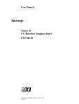
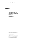
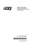
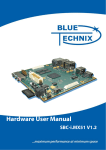
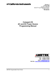
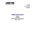
Figure 1–1 shows a functional block diagram of the VX4330. Figure 1–2 shows
a typical SurePatht configuration.
1–2
VX4330 120-Channel Relay Multiplexer Module User Manual
Getting Started
Section 1
Section 6
1-Wire_1a
1-Wire_6a
1-Wire_1a_Res
1-Wire_6a_Res
Com_1b_Hi_Res
Com_6b_Hi_Res
Com_1b_Lo_Res
Com_6b_Lo_Res
Com_1a_Hi_Res
Com_6a_Hi_Res
Com_1a_Lo_Res
Com_1b_Hi
Com_6a_Lo_Res
Com_1b_Lo
Com_6b_Lo
Com_6b_Hi
Com_1a_Hi
2 wire/
4 wire
2 wire/
4 wire
Com_1a_Lo
Com_6a_Hi
Com_6a_Lo
In_10b_Hi
In_10b_Hi
In_10b_Lo
In_10b_Lo
In_10a_Hi
In_10a_Hi
In_10a_Lo
In_10a_Lo
In_1b_Hi
In_1b_Hi
In_1b_Lo
In_1b_Lo
In_1a_Hi
In_1a_Hi
In_1a_Lo
In_1a_Lo
Join
1b-2b
Join
2b-3b
Join
3b-4b
Join
4b-5b
Join
5b-6b
Join
1a-2a
Join
2a-3a
Join
3a-4a
Join
4a-5a
Join
5a-6a
Figure 1–1: VX4330 Functional Block Diagram
VX4330 120-Channel Relay Multiplexer Module User Manual
1–3
Getting Started
VXI interface &
slave controller
daughter board
Backplane
connectors
Front panel
connectors
VXI backplane
local bus
Daughter board
connectors
Figure 1–2: Typical SurePath Configuration
Fuses
The VX4330 Module has one 5 amp fast-acting fuse on the +5 V line.
Each relay module that the Option 01 Module controls has a fuse that limits the
amount of current that the module can draw from the VXI backplane +5 V power
pins. This fuse protects the module in case of an accidental shorting of the power
bus or any other situation where excessive current might be drawn.
The Option 01 Module monitors the state of the fuses of each of the relay
modules that it controls. If a fuse opens on one of these modules, the Option 01
Module will assert SYSFAIL* on the VXIbus.
If the +5 V fuse on the module on which the Option 01 Module is installed
opens, the VXIbus Resource Manager will be unable to assert SYSFAIL
INHIBIT on the Option 01 to disable SYSFAIL*.
If a +5 V fuse opens, remove the fault before replacing the fuse. Replacement
fuse information is given in the Specifications section of the user manual for the
appropriate relay module.
1–4
VX4330 120-Channel Relay Multiplexer Module User Manual
Getting Started
LEDs
BITE (Built-in Test
Equipment)
The following LEDs are visible in the middle of the VX4330 Module’s front
panel to indicate the status of the module’s operation (see Figure 1–5).
Power LED
indicates power is applied to the module
Failed LED
indicates the module is in the FAILED state
Built-in Test Equipment (BITE) is provided by extensive self tests that are
automatically invoked on power-on and can also be invoked on command.
Circuitry tested includes the CPU and all memory, and the relay control circuitry
on each relay module controlled by the Option 01.
Accessories
Table 1–1 lists the standard accessories included with the VX4330.
Table 1–1: Standard Accessories
Accessory
Part Number
VX4330 User Manual
070-9178-XX
VX4330 Reference
070-9200-XX
Fuse
159-0207-00
Table 1–2 lists the options available for the VX4330.
Table 1–2: Options
Option
Part Number
01 VXI Interface Kit
040-1510–XX
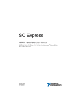
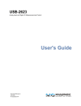
Controls and Indicators
The following controls are provided on the Option 01 to select the functions of
the VX4330 operating environment. Figures 1–3 and 1–4 illustrate the physical
location of these controls and indicators.
Switches
The Logical Address switches and VMEbus Interrupt Level Select switch on the
Option 01 must be correctly set to insure proper operation. See Configuration for
details on how to set the switches.
VX4330 120-Channel Relay Multiplexer Module User Manual
1–5
Getting Started
LOGICAL
ADDRS
LO
Option 01
HI
INTRPT
Switches as viewed
from the rear of instrument
(labels are on the back shield)
F1291
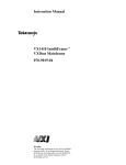
Figure 1–3: VX4330 Connectors, Indicators, and Switch Locations
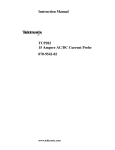
Figure 1–4: VX4330 Front Panel
1–6
VX4330 120-Channel Relay Multiplexer Module User Manual
Getting Started
Configuration
The following switches are located on the Option 01 Module, and must be
correctly set to ensure proper operation. Refer to Figure 1–3 for their physical
locations.
If the Option 01 is not installed on this module, then this module must be to the
right of the module with the Option 01. Refer to the Option 01 User Manual for
information on system configuration.
Logical Address Switches
Each functional module in a VXIbus System must be assigned a unique logical
address, from 1 to decimal 255 (hexadecimal FF). The base VMEbus address of
the VX4330 is set to a value between 1 and hexadecimal FF (FF16) by two
hexadecimal rotary switches. Align the desired switch position with the arrow on
the module shield.
The physical address of the instrument is on a 64 byte boundary. If the Logical
Address switch representing the most significant digit (LA–HI) of the logical
address is set to position X and the switch representing the least significant digit
(LA–LO) of the logical address is set to position Y, then the base physical
address of the VX4330 will be [(4016 × XY16) + C00016]. For example:
Base Physical Address
L.A.
HI
LO
decimal
hex
A16
016
A16
(64 * 10) + 49152 = 49792
(4016 * A16) + C00016 = C28016
1516
116
516
(64 * 21) + 49152 = 50496
(4016 * 1516) + C00016 = C54016
LA. is the Logical Address
IEEE-488 Address
In order to use and program the VX4330 Module in an IEEE-488 environment
you must know the IEEE-488 address of the module. Different manufacturers of
IEEE-488 interface devices might have different algorithms for equating a
logical address with an IEEE-488 address. Consult the operating manual of the
IEEE-488 Interface Module being used.
VMEbus Interrupt Level
Select Switch
Each function module in a VXIbus System can generate an interrupt at a
specified level on the VMEbus to request service from the interrupt handler
located on its commander. Set the interrupt level to the same level as the
interrupt handler on that commander. The VMEbus interrupt level on which the
VX4330 Module generates interrupts is set by a rotary switch. Align the desired
switch position with the arrow on the module shield.
Valid VMEbus Interrupt Level Select switch settings are one through seven, with
setting one equivalent to level one, and so on. The level chosen should be the
VX4330 120-Channel Relay Multiplexer Module User Manual
1–7
Getting Started
same as the level set on the VX4330 interrupt handler, typically the module
commander. Setting the switch to zero or eight will disable the module interrupts. Do not use switch settings nine through f.
Interrupts are used by the module to return VXIbus Protocol Events to the
module commander. Refer to the Operating Basics section for more information
on interrupts. The VXIbus Protocol Events supported by the module are listed in
Appendix A: Specifications.
Installation
This section describes how to install the VX4330.
Tools Required
Requirements and
Cautions
A slotted screwdriver set is required for proper installation.
The VX4330 Module is a C-size VXIbus instrument module and therefore may
be installed in any C- or D-size VXIbus mainframe slot other than slot 0. To
install the module in a D-size mainframe, consult the operating manual for the
mainframe. Refer to Configuration for information on selecting and setting the
Logical Address switch of the module. This switch defines the programming
address of your module. To avoid confusion, it is recommended that the slot
number and the logical address be the same.
NOTE. Note that there are two printed ejector handles on the card. To avoid
installing the card incorrectly, make sure the ejector marked “VX4330” is at the
top.
NOTE. Verify that the mainframe is able to provide adequate cooling and power
with this module installed. Refer to the mainframe Operating Manual for
instructions.
If the VX4330 is used in a Tektronix mainframe, all VX4330 cooling requirements are met.
NOTE. If the VX4330 is inserted in a slot with any empty slots to the left of the
module, the VME daisy-chain jumpers must be installed on the backplane in
order for the VXI Module to operate properly. Check the manual of the mainframe being used for jumpering instructions. Jumpers are not necessary for
autoconfiguring backplane designs.
1–8
VX4330 120-Channel Relay Multiplexer Module User Manual
Getting Started
Installation Procedure
Follow these steps to install the VX4330. If the module has Option 01, first refer
to the Option 01 User Manual for instructions on mounting the option.
CAUTION. The VX4330 Module is a piece of electronic equipment and therefore
has some susceptibility to electrostatic damage (ESD). ESD precautions must be
taken whenever the module is handled.
1. Record the revision level, serial number (located on the label on the shield of
the VX4330), and switch settings on the Installation Checklist.
2. Verify that the switches are set to the correct values. Refer to Configuration
for more information on setting switches.
3. Make sure that the mainframe power is off.
4. Insert the module into one of the instrument slots of the mainframe (see
Figure 1–5).
5. Cable Installation: Use the correct cable to interface between the module I/O
connector and the Unit Under Test (UUT). The recommended cable is listed
in Appendix A: Specifications.
Figure 1–5: Module Installation
VX4330 120-Channel Relay Multiplexer Module User Manual
1–9
Getting Started
Installation Checklist
Installation parameters will vary depending on the mainframe being used. Be
sure to consult the mainframe operating manual before installing and operating
the module.
Revision Level: ___________
Serial No.: ___________
Mainframe Slot Number: ___________
Switch Settings: ___________
VXIbus Logical Address Switch: ___________
Interrupt Level Select Switch: ___________
Cable Installed (if any): ___________
Performed by: _______________________
1–10
Date: _____________
VX4330 120-Channel Relay Multiplexer Module User Manual
Getting Started
Functional Check
In addition to the self tests, you can also perform an operational check of the
VX4330.
Self Test
The VX4330 120-Channel Relay Multiplexer Module executes a self test at
power-on, on direction of a VXIbus hard or soft reset condition, or on command.
The power-on self test consists of an interface self test and an instrument self
test. The self test requested by command performs only the instrument self test.
A VXIbus hard reset occurs when another device, such as the VXIbus Resource
Manager, asserts the backplane line SYSRESET*. A VXIbus soft reset occurs
when another device, such as the VX4330 commander, sets the Reset bit in the
VX4330 Control register.
During power-on, or a hard or soft reset, the following actions take place:
1. The SYSFAIL* (VME system-failure) line is set active, indicating that the
module is executing a self test, and the Failed LED is lighted. For a soft
reset, SYSFAIL* is set. All Tektronix commanders will simultaneously set
SYSFAIL INHIBIT to prevent the resource manager from prematurely
reporting the failure of a card.
2. On completion of the interface self test, SYSFAIL* is de-asserted. If the test
fails, the SYSFAIL* line remains active. If the interface self test passed, the
SYSFAIL* line is released, and the module enters the VXIbus PASSED state
(ready for normal operation). If it failed, the module enters the VXIbus
FAILED state.
3. The instrument self test, as described in the *TST? command description, is
then executed. This tests the Option 01 VXI Interface daughter board and
any relay modules under its control. If the self test fails, the module makes
an internal record of the failure(s) that occur.
The default condition of the Option 01 Module after the completion of power-on
self test is as follows:
All relays on modules controlled by the Option 01 (except VX4320
Modules) are set to the open position.
You can run the self test at any time during normal operation by using the *TST?
command. At the end of a self test initiated by this command, the module is
restored to its pre-test state.
VX4330 120-Channel Relay Multiplexer Module User Manual
1–11
Getting Started
During a commanded self test:
1. SYSFAIL* is not asserted.
2. The module executes the same instrument self test as is executed upon power
on.
3. When the self test is completed, the modules controlled by the Option 01 are
restored to their pre-test state.
Operational
Check
Perform an operational check of the VX4330 by checking the continuity of the
switch closures using an ohmmeter or a test light.
When equipped with the Option 01 VXI Interface, the commands
will open all of the relay paths. All relays on the VX4330 will also be opened
automatically on power-on. Figure 1–1 VX4330 Functional Block Diagram
shows the configuration of the VX4330 with all paths open. Refer to Appendix
B: Input/Output Connections for the connector pinouts and the Functional Block
Diagram, and use a continuity tester to verify that all inputs are open to their
associated commons, and that the commons of adjacent sections are disjoined.
The command
will close the 4-wire switch path from input 1 of section 1 to the common of
section 1 (In_1a_Lo, In_1a_Hi, In_1b_Lo and In_1b_Hi of Section 1 to
Com_1a_Lo, Com_1a_Hi, Com_1b__Lo, and Com_1b_Hi respectively). Then
check the continuity. Be careful to prevent damage to the pins of the front panel
connectors.
Note that true measurement of the resistance of the path requires a high-resolution instrument and special procedures which are beyond the scope of this check.
Use the command
to close the 4-wire switch path from input 2 of section 1 to the common of
section 1. Check for continuity of the four paths.
Use the command
1–12
VX4330 120-Channel Relay Multiplexer Module User Manual
Getting Started
incrementing the input channel number (c) from 1 through 10 for each value of
the section number (s) from 1 through 6 to close the 4-wire switch path from
input c of section s to the common of section s. Check for continuity of the four
paths each time.
Use the command
incrementing s from 2 through 6 to close the 4-wire common of section 1 to the
4-wire commons of sections 2 through s. Check for continuity of the four paths.
Use the commands
to open all the relays. Check continuity of 1-Wire_1a through 1-Wire_6a to
Com_1a_Hi through Com_6a_Hi respectively.
Use the commands
to close 1-Wire_1a to In_1a_Lo, Com_1a_Lo and Com_1b_Lo. Check for
continuity of this path.
Use the commands
to close 1-Wire_sa to In_sa_Lo, Com_sa_Lo and Com_sb_Lo, incrementing s
from 2 through 6. Check for continuity of each path.
By testing in this manner, you can verify that the module is operational.
SYSFAIL* Operation
SYSFAIL* becomes active during power-on, hard or soft reset, or self test, or if
the module loses any of its power voltages. When the mainframe Resource
Manager detects SYSFAIL* set, it will attempt to inhibit the line. This causes
the VX4330 120-Channel Relay Multiplexer Module to deactivate SYSFAIL*
except when +5 V power is lost on the relay module on which it is installed.
VX4330 120-Channel Relay Multiplexer Module User Manual
1–13
Operating Basics
The VX4330 120-Channel Relay Multiplexer Module is a VXIbus messagebased instrument and communicates using the VXIbus Word Serial Protocol. The
module is programmed by issuing ASCII characters from the system controller
to the VX4330 via the module VXIbus commander and the VXIbus mainframe
backplane. Refer to the manual for the VXIbus device that will be the VX4330
Module commander for details on the operation of that device.
If the module commander is a Tektronix IEEE-488 Interface Module, refer to the
operating manual for the module and Appendix C: Examples in this manual for
information on how the system controller communicates with the commander
being used.
Functional Overview
The VX4330 provides six 1 × 10 4-wire multiplexer (mux) sections. Each of
these six sections can be independently configured under software control as two
1 × 10 2-wire muxes, a 1 × 20 2-wire mux, or as a 1 × 40 1-wire mux. In
addition, each section can be programmed to connect it to the section above or
below it to produce up to a 1 × 60 4-wire mux, a 1 × 120 2-wire mux, or a
1 × 240 1-wire mux.
Power-on
The instrument runs its self test and is ready for programming five seconds after
power-on. The VXIbus Resource Manager can add an additional delay. The
Power LED of each relay module controlled by the Option 01 will be on. The
Failed LED on each of these modules will be off. The default condition of the
module after power-on is listed in the *RST command description. Self-test
failures are described in the SYSTem:ERRor? command description.
The format and syntax for the command strings are described in the Command
Syntax section. A complete description of each command in alphabetical order is
in the Command Descriptions section.
VX4330 120-Channel Relay Multiplexer Module User Manual
2–1
Operating Basics
Instrument I/O: VXIbus Basics
NOTE. If the user’s mainframe has other manufacturers’ computer boards
operating in the role of VXIbus foreign devices, the assertion of BERR* (as
defined by the VXIbus Specification) may cause operating problems on these
boards.
The Option 01 Module installed on a switching module is a C-size single slot
VXIbus Message-Based Word Serial instrument. It uses the A16, D16 VME
interface available on the backplane P1 connector and does not require any A24
or A32 address space. The module is a D16 interrupter.
The Option 01 is neither a VXIbus commander nor a VMEbus master; therefore
it does not have a VXIbus Signal register. The Option 01 is a VXIbus messagebased servant.
The module supports the Normal Transfer Mode of the VXIbus using the Write
Ready, Read Ready, Data In Ready (DIR), and Data Out Ready (DOR) bits of
the module Response register.
A Normal Transfer Mode read of the Option 01 proceeds as follows:
1. The commander reads the Option 01 Response register and checks if the
Write Ready and DOR bits are true. If they are, the commander proceeds to
the next step. If not, the commander continues to poll these bits until they
become true.
2. The commander writes the Byte Request command (hexadecimal 0DEFF) to
the Data Low register of the Option 01.
3. The commander reads the Option 01 Response register and checks if the
Read Ready and DOR bits are true. If they are, the commander proceeds to
the next step. If not, the commander continues to poll these bits until they
become true.
4. The commander reads the Option 01 Data Low register.
A Normal Transfer Mode write to the Option 01 proceeds as follows:
1. The commander reads the Option 01 Response register and checks if the
Write Ready and DIR bits are true. If they are, the commander proceeds to
the next step. If not, the commander continues to poll the Write Ready and
DIR bits until they are true.
2. The commander writes the Byte Available command which contains the data
(hexadecimal 0BCXX or 0BDXX, depending on the End bit) to the Data
Low register of the Option 01.
2–2
VX4330 120-Channel Relay Multiplexer Module User Manual
Operating Basics
The module also supports the Fast Handshake Mode during readback. In this
mode, the module is capable of transferring data at optimal backplane speed
without needing the commander to test any of the handshake bits. The Option 01
asserts BERR* to switch from Fast Handshake Mode to Normal Transfer Mode,
per VXI Specification. The Option 01 Read Ready, Write Ready, DIR and DOR
bits react properly, in case the commander does not support the Fast Handshake
Mode.
A Fast Handshake Transfer Mode read of the Option 01 proceeds as follows:
1. The commander writes the Byte Request command (hexadecimal 0DEFF) to
the Option 01 Data Low register.
2. The commander reads the Option 01 Data Low register.
A Fast Handshake Transfer Mode write of the Option 01 proceeds as follows:
The commander writes the Byte Available command which contains the data
(hexadecimal 0BCXX or 0BDXX, depending on the End bit) to the Data
Low register of the Option 01. The commander may immediately write
another Byte Available command without having to check the Response
register.
The module has no registers beyond those defined for VXIbus message based
devices. All communications with the module are through the Data Low register,
the Response register, or the VXIbus interrupt cycle. Any attempt by another
module to read or write to any undefined location of theOption 01 address space
may cause incorrect operation of the module.
As with all VXIbus devices, the Option 01 has registers located within a 64 byte
block in the A16 address space. The base address of the Option 01 device
registers is determined by the device unique logical address and can be calculated as follows:
Base Address = V16 * 4016 + C00016
where V is the device logical address as set by the Logical Address switches.
VX4330 120-Channel Relay Multiplexer Module User Manual
2–3
Operating Basics
Configuration Registers
Table 2–1 lists the Configuration registers and a complete description of each
register. The offset is relative to the module base address.
Table 2–1: Register Definitions
Register
Address
(hexadecimal)
Type
Value (Bits 15–0)
ID Register
0000
RO
1011 1111 1111 1100 (hexadecimal BFFD)
Device Type
0002
RO
See Device Type definition below
Status
0004
R
Defined by state of interface
Control
0004
W
Defined by state of interface
Offset
0006
WO
Not used
Protocol
0008
RO
1111 0111 1111 1111 (hexadecimal F7FF)
Response
000A
RO
Defined by state of the interface
Data High
000C
Data Low
000E
W
Not fixed; command–dependent
Data Low
000E
R
Not fixed; command-dependent
Not used
RO is Read Only
WO is Write Only
R is Read
W is Write
The Register Bit definitions are listed in Tables 2–2 and 2–3.
Table 2–2: Register Bit Definitions
2–4
Register
Bit Definition
ID
hexadecimal BFFC
Protocol
hexadecimal F7FF
VX4330 120-Channel Relay Multiplexer Module User Manual
Operating Basics
Device. The contents of the Device register of the Option 01 Module depends on
the model number of the relay module that it is installed on, as shown in
Table 2–3.
Table 2–3: Device Register Bit Definitions
Relay Model No.
Device Register Contents
VX4320
hexadecimal FCBF
VX4330
hexadecimal F6B5
VX4350
hexadecimal F6A1
VX4380
hexadecimal F683
VX4330 120-Channel Relay Multiplexer Module User Manual
2–5
Command Syntax
Command protocol and syntax for the VX4330 Module are as follows:
H
A command string consists of a string of ASCII-encoded characters
terminated by a <program message terminator>. The <program message
terminator> is optional white space, followed by any one of the following
command terminations:
a line feed <LF> or new line <NL> character (hexadecimal 0A,
decimal 10)
the END bit set
the END bit with a line feed <LF> or new line <NL>
The command string is buffered until the terminator is encountered, at which
time the entire string is processed.
H
In addition to terminating a command, the semi-colon character directs the
SCPI command parser to interpret the next command with the assumption
that all characters up to and including the last colon in the previous
command have just been parsed. In the following example, the Option 01 is
installed on a VX4380 Module. Two additional VX4380 Modules are
installed in consecutive slots to the right of the first VX4380. Under these
conditions, the commands
cause all relays on all three VX4380 Modules to open. Note that each of
these commands is terminated by a line feed. An equivalent method of
sending these commands using the semi-colon character as a terminator is
After a line feed or END bit is used to terminate a command, the parser no
longer makes the assumption described above. Thus, after the command
is parsed, the command
is no longer valid.
VX4330 120-Channel Relay Multiplexer Module User Manual
3–1
Command Syntax
In the next example, the Option 01 is installed on a VX4330 Module. Two
additional VX4330 Modules are installed in consecutive slots to the right of
the first VX4330. The commands
connect the commons of sections 1 through 6 on the first VX4330, sections 1
and 2 on the second VX4330 and sections 1 through 4 on the third VX4330.
An equivalent way to send these commands using the semi-colon as a
terminator is
Note that <LF> in these examples represents a single line feed character.
H
White space characters can be used to make a command string more
readable. These characters are ASCII-encoded bytes in the range hexadecimal 00–09 and 0B–20 (decimal 0–9 and 11–32). This range includes the
ASCII control characters and the space, but excludes the line feed <NL>.
White space characters are ignored when legally encountered in a command
string. White space is allowed anywhere in a command string, except for the
following:
Within a program mnemonic ( for example RO UTE )
Around a colon (:) mnemonic separator (for example ROUTE: CLOSE
or ROUTE :CLOSE)
Between a mnemonic and a (?) (for example CLOSE ?)
Following an asterisk (*) (for example * STB?)
Within a number (for example 12 34)
Within a module name specified in a [ROUTe:]MODule[:DEFine]
command (for example ROUTE:MODULE:DEFINE RFM UX, 1).
At least one white space character is required between a command/query
header and its associated arguments. For example in the command
the command header is the string “route:configure:join”. The arguments
associated with this command are the module name “m1” and the section list
“(1:6)”. At least one white space character must be sent before the first
argument.
3–2
VX4330 120-Channel Relay Multiplexer Module User Manual
Command Syntax
In the query
)',+ $'* %
the query header is the string “route:close?”. The argument associated with
this query is the channel list “(@m1(1:64))”. At least one white space
character must be sent before the channel list argument.
Syntax Example
H
All characters in a command can be sent in either upper or lower case form.
H
Multiple data parameters passed by a command are separated by a comma
(,).
H
A question mark (?) following a command indicates that a response will be
returned. All responses from the module are terminated with a carriage return
<CR> and a line feed <LF> (hexadecimal 0A) character.
H
In the command descriptions, the following special characters are used.
Except for the colon (:), these characters are not part of the command and
should not be sent. If an optional field is omitted, the default for the
command is applied.
[]
Brackets indicate an optional field
|
A bar indicates a logical OR choice
:
A colon is used to separate command fields
<>
Field indicator
Capital letters indicate the minimum required characters which need to be sent.
Lower case letters are optional. For example, the syntax of the trigger source
command is given as
! ), & - - #+
- )!&
Each of the following is a valid form of this command:
+)#!! )* (, & *',) ,*
+)#!* (*',) "'$
)#! )#!',) )#!',) )#!! )',) %% #+
VX4330 120-Channel Relay Multiplexer Module User Manual
3–3
Command Syntax
SCPI/IEEE 488.2
Command Elements
The definition of elements used in SCPI/IEEE 488.2 commands and command
descriptions is as follows:
<NR1> ASCII integer representation of a decimal number.
<NRf> ASCII integer, fixed point or floating point representation of a decimal
number.
<module_name> A user-defined ASCII string to be associated with the local bus
address of a relay module. <module_name> strings must start with a letter and
may consist of alphanumeric characters, underscores, and digits. The maximum
length of a <module_name> is 12 characters.
<channel_spec> One or more <NR1> ASCII strings separated by “!” characters
that specify a relay on a relay module. The format of a <channel_spec> field for
each of the SurePath relay modules is:
H
VX4320 RF Multiplexer: <NR1> ! <NR1>
The range of the first <NRf> field is 1 to 4. This field specifies a relay
within one of the sections of the VX4320. The range of the second <NRf>
field is 1 to 8. This field specifies a section of the VX4320. A one-dimensional <channel_spec> may also be used to specify a channel on a VX4320
Module. The one-dimensional <channel_spec> is given by the formula:
( (section – 1 ) × 4 ) + relay
where variables “section” and “relay” are section and relay numbers
specified in a two-dimensional <channel_spec>.
H
VX4330 Scanner/Multiplexer: <NR1> ! <NR1>
The first <NR1> field specifies a relay within the specified section. The
range of this <NR1> field depends on the current configuration of the section
of the VX4330 specified in the second <NR1> field. The range of the second
<NR1> field is 1 to 6. This field specifies a section of the VX4330.
3–4
1 – 10
4-wire
1 – 20
4-wire independent
1 – 20
2-wire
1 – 40
1-wire
VX4330 120-Channel Relay Multiplexer Module User Manual
Command Syntax
H
VX4350 General Purpose Switching module: <NR1>
The range of this field is 1 to 64. It specifies one of 64 relays on the
VX4350.
H
VX4380 Matrix: <NR1> ! <NR1> ! <NR1>
The range of the first <NR1> field is 1 to 4. It specifies the row of a relay in
one of the sections of the VX4380. The range of the second <NR1> field is 1
to 16. It specifies the column of a relay in one of the sections of the VX4380.
The range of the third <NR1> field is 1 to 4. It specifies a section of the
VX4380. A one dimensional <channel_spec> may also be used to specify a
channel on a VX4380 Module. The one dimensional <channel_spec> is
given by the formula:
( (section – 1 ) × 64 ) + ( ( row – 1 ) × 16 ) + column
where variables “section” and “row” and “column” are section, row, and
column numbers specified in a three-dimensional <channel_spec>.
<channel_list> A list of channel numbers on one or more relay modules.
The limits on the channel numbers in a <channel_list> depend on the model
number of the relay module(s) specified in the <channel_list>. The syntax of a
<channel_list> is shown in the following diagram:
A module_name is an ASCII string that has been associated with a relay module
in a ROUTe:MODule:DEFine command. A channel_range may consist of a
single <channel_spec> or a range of <channel_spec>s. A range of <channel_spec>s is indicated by two <channel_spec>s separated by a colon (:)
character. A <channel_spec> may have one, two or three dimensions depending
on the architecture of the relay module it applies to.
VX4330 120-Channel Relay Multiplexer Module User Manual
3–5
Command Syntax
The following are examples of valid <channel_list>s for Tektronix VX4320,
VX4330, VX4350, VX4372, VX4374, and VX4380 relay modules. In these
examples it is assumed that the Option 01 is installed on a VX4320 Module. A
VX4330, VX4350, VX4372, VX4374, and VX4380 are installed in consecutive
slots to the right of the VX4320. The default module names for the VX4320,
VX4330, VX4350, VX4372, VX4374 and VX4380 in this example are m1, m2,
m3, m4, m5, and m6 respectively. These module names may be overridden by
specifying new module names with the [ROUTe:]MODule[DEFine] command. It
is also assumed in these examples that all sections on the VX4330 Module have
been configured as 10-to-1 4-wire scanners.
3–6
<channel_list>
Channels Specified
Channel number 1 of section 2 on the VX4320 Module.
Channel number 4 in section 1 and relay number 3 in section 8
of the VX4320 Module.
Channel number 4 in sections 1 through 8 on the VX4320
Module.
Channel number 4 in sections 1 through 8 on the VX4320
Module.
Channel 1 in section 6 of the VX4330 Module.
All channels on the VX4330 Module in the following order: 1!1,
1!2, 1!3, 1!4, 1!5, 1!6, 2!1, 2!2, 2!3, 2!4, 2!5, 2!6, ... , 10!1,
10!2, 10!3, 10!4, 10!5, 10!6.
All 10 channels in section 3 of the VX4330.
All 64 channels on the VX4350
Channels 1, 2, 3, 10, 11, and 20 through 13 on the VX4350.
Channel 1 in section 2 of the VX4372.
Channel 3 in section 1 of the VX4374.
The channel that connects row 1 to column 13 in section 3 of
the VX4380.
The channel that connects row 1 to column 1 in section 2 of
the VX4380.
Same as the previous example.
The channels that connect columns 1 through 16 to row 1 in
section 1 of the VX4380.
Same as the previous example.
Channels 1!1!1, 1!1!2, 1!1!3, 1!1!4, 1!2!1, 1!2!2, 1!2!3, 1!2!4,
1!3!1, 1!3!2, 1!3!3, 1!3!4, 2!1!1, 2!1!2, 2!1!3, 2!1!4, 2!2!1,
2!2!2, 2!2!3, 2!2!4, 2!3!1, 2!3!2, 2!3!3, 2!3!4 on the VX4380
Module.
VX4330 120-Channel Relay Multiplexer Module User Manual
Command Syntax
As the <channel_list> syntax diagram shows, channels on more than one relay
module may be specified in a <channel_list>. The next example specifies
channels on three different relay modules.
<channel_list>
Channels Specified
(@m1(1!1), m2(4!6),
m6(3!13!2))
Channel 1 of section 1 on the VX4320, Channel 4 of section 6
of the VX4330, and the channel on the VX4380 that connects
row 3 to column 13 in section 2.
As mentioned above, the module names used in <channel_list>s may be
specified with a [ROUTe:]MODule[:DEFine] command. The command
route:module:Define rfmux, 1
changes the module name assigned to the VX4320 to “rfmux”. The following
<channel_list> can then be used to specify channels on the VX4320.
(@rfmux(3!1,2!2))
specifies channel 3 in section 1 and channel 2 in section 2 of the VX4320.
The order in which channels are specified is important in the [ROUTe:] CLOSE?
<channel_list> and [ROUTe:]OPEN? <channel_list> queries. The states of the
channels are returned in the same order that the channels are specified in the
<channel_list>.
The order in which channels are specified is also important in the [ROUTe:]
SCAN <channel_list> command. This determines the order in which the relays
will be closed each time a trigger event is detected.
The order in which channels are specified in a <channel_list> is important in the
[ROUTe:]CLOSe <channel_list> command when channels in the same section of
a VX4320 or a VX4330 are specified. A VX4320 can close only one channel in a
section. If a [ROUTe:]CLOSE <channel_list> command specifies more than one
relay in a section of a VX4320, the last channel in the <channel_list> will be
closed.
For example, the command
close (@m2(1!1,2!1))
will close channel 2 of section 1 of the VX4320.
A VX4330 can close only one channel in a group of joined sections that have
been specified in a [ROUTe:]CLOSe:MODe SCAN,<module_name>,<section_list> command. If more than one channel in such a group of sections is
specified in a [ROUTe:]CLOSe <channel_list> command, the last channel
specified will be closed. For example, the commands
VX4330 120-Channel Relay Multiplexer Module User Manual
3–7
Command Syntax
route:configure:join m2,(1:6)
route:close:mode scan,m2,(1:6)
join the commons of all six sections of the VX4330 Module and set the mode of
the [ROUTe]:CLOSE <channel_list> to scan mode for all six sections of the
VX4330.
The command
route:close (@m2(1!1,1!6))
will then result in channel 1 of section 6 being closed and all other channels on
the module being opened.
output queue The Output queue of the Option 01 VXI Interface is used to return
replies to queries received by the interface. Bit 4 (the MAV bit) of the Status
Byte register is set to indicate that this queue is not empty. The DOR bit in the
VXI Response register is also set to indicate that this queue is not empty. The
commander of the Option 01 VXI Interface monitors the DOR bit to determine
when it may read a message from the Output queue.
<section_list> One or more <nr1> fields separated by comma (,) or colon (:)
characters and enclosed in left and right parentheses. A <section_list> is used to
specify the sections of a relay module to be acted upon by a [ROUTe:]CONFigure or [ROUTe:]CLOSe:MODE command. The following are examples of valid
<section_list>s.
For commands directed to a VX4330 which has six scanner sections:
3–8
<section_list>
Sections Specified
(1:6)
Sections 1 through 6
(1,2,3)
Sections 1, 2 and 3
(1:3,5:6)
Sections 1 through 3 and 5 and 6
(1:3,5,6)
Same as previous example
(3)
Section 3
VX4330 120-Channel Relay Multiplexer Module User Manual
Command Syntax
For commands directed to a VX4372 or VX4374 which has two scanner
sections:
<section_list>
Sections Specified
Section 1
Sections 1 and 2
Sections 1 and 2
error/event queue When the command parser detects a syntax error or data range
error, it places an error message describing the error in the Error/Event queue.
Bit 2 of the Status Byte Register is set to indicate that this queue is not empty.
Bit 5 of the Standard Event Status Register (the Command Error bit) is set if the
parser detects a syntax error. Bit 4 of the Standard Event Status register (the
Execution Error bit) is set if the parser detects a numeric argument that is out of
range. When a SYSTem:ERRor? query is received, an error message is dequeued
from the Error/Event queue and placed in the Output queue.
VX4330 120-Channel Relay Multiplexer Module User Manual
3–9
Functional Command Groups
This section lists the VX4330 system and module commands.
System Commands
The following low-level commands are typically sent by the module’s commander, and are transparent to the user of the module. (An exception is the Read STB
command, which is sent whenever a Serial Poll on an IEEE-488 system is
performed.) Most commanders or Slot 0 devices have specific ASCII commands
that cause the commander to send one of these low-level commands to a
specified instrument. Refer to the operating manual of the commander or Slot 0
device for information on these commands.
Command
Effect
Begin Normal Operation
The module begins operation if it has not already done so.
Byte Available
Transfers module commands to this module.
Byte Request
Requests the module to return a byte of data from the output
queue.
Clear
The module clears its VXIbus interface and any pending
commands. Current module operations are unaffected.
Clear Lock
Clears the Lock bit of the Response register.
Read Protocol
The module returns its protocol to its commander.
Read STB
The module returns its VXI status byte to its commander.
Set Lock
Set the Lock bit of the Response register.
Trigger
Close the next relay in a scan list that has been defined by a
ROUTe:SCAN <channel_list> command. A VXI Trigger
command is enabled as a trigger source by a ROUTe:SEQuence:SOURce BUS command.
Module Commands
A summary of the VX4330-specific and IEEE-488.2 Common Commands is
listed in Tables 3–1 and 3–2 below. The next section, Command Descriptions,
includes detailed descriptions of each command. Appendix C: Examples shows
examples of command usage.
VX4330 120-Channel Relay Multiplexer Module User Manual
3–11
Functional Command Groups
Table 3–1: Summary of VX4330-Specific SCPI Commands
Subsystem Command
Functions Controlled
ABORt
Place initiated scan in the idle state
CLOSe
Close specified relays; DWELl
CONFigure
Configuration: DISJoin, JOIN
ID?
Return model numbers of modules controlled by the Option 01
INITiate
Place trigger subsystem in armed state: IMMediate,
CONTinuous
MODule
Module name functions: DEFine, CATalog?, DELete
MODE
VX4330 only; set mode to scan or mux
OPEN
Open specified relays: ALL, DWELl
OUTPut
Enable or disable selected VXI TTL trigger
PFAil
Specify state of latching relays on powerfail
SCAN
Define a list of relay closures to scan through
STATus
Status register functions: OPERation, QUESstionable
SYSTem
System-level functions: ERRor?, PRESet, VERSion?
TRIGger
Scan list functions: COUNt, DELay, IMMediate, SOURce
Table 3–2: Summary of IEEE-488.2 Common Commands
3–12
Command/Syntax
Description
Clear Status
*CLS
Clears the SCPI and IEEE 488.2 event registers and
the SCPI error/event queue, and the output queue.
Standard Event Status Enable
*ESE <NRf>
Sets the contents of the Standard Event Status Enable
register.
Standard Event Status Enable Query
*ESE?
Returns the current value of the Standard Event
Status Enable register in <nr1> format.
Standard Event Status Register Query
*ESR?
Returns the current value of the Standard Event
Status register in <nr1> format, then set the contents
of this register to 0.
Identification Query
*IDN?
Returns an ASCII string in the output queue which
identifies the board.
Operation Complete
*OPC
Sets bit 0 (the Operation Complete bit) of the
Standard Event Status register when all pending
device operations have been completed.
Operation Complete Query
*OPC?
Places the ASCII character 1 in the output queue
when all pending device operations have been
completed.
VX4330 120-Channel Relay Multiplexer Module User Manual
Functional Command Groups
Table 3–2: Summary of IEEE-488.2 Common Commands (Cont.)
Command/Syntax
Description
Reset*
*RST
The Option 01 VXI interface is placed in its power-up
state with some exceptions.
Service Request Enable
*SRE <NRf>
Sets the contents of the Service Request Enable
register.
Service Request Enable Query
*SRE?
Returns the current value of the Service Request
Enable register in <nr1> format.
Read Status Byte Query
*STB?
Returns the current value of the Status Byte register in
<nr1> format.
Trigger
*TRG
Equivalent to a VXI Trigger command.
Self-Test Query
*TST?
Performs a self test of the Option 01 VXI Interface
daughter board and any relay modules under its
control. Place a “0” or “1” into the output queue to
indicate whether the self test passed or failed.
Wait-to-Continue
*WAI
Does not execute any further commands or queries
until all pending operations have been completed.
VX4330 120-Channel Relay Multiplexer Module User Manual
3–13
Command Descriptions
This section lists the VX4330-specific SCPI commands and queries in alphabetic
order. The IEEE-488.2 Common Commands are listed in the next section. A
summary listing of the SCPI command set for the Option 01 is as follows:
ABORt
[ROUTe:]CLOSe <channel_list>
[ROUTe:]CLOSe:DWELl <module_name>,<nrf>
[ROUTe:]CLOSe:MODE <mode>,<module_name>,<section_list>
[ROUTe:]CONFigure <configuration>,<module_name>,<section_list>
[ROUTe:]CONFigure:DISJoin <module_name>
[ROUTe:]CONFigure:JOIN <module_name>,<section_list>
[ROUTe:]ID?
INITiate:CONTinuous
INITiate[:IMMediate]
[ROUTe:]MODule[:DEFine] <module_name>,<nrf>
[ROUTe:]MODule:CATalog?
[ROUTe:]MODule:DELete[:NAME] <module_name>
[ROUTe:]MODule:DELete:ALL
[ROUTe:]OPEN <channel_list>
[ROUTe:]OPEN:ALL [module_name]
[ROUTe:]OPEN:DWELl <module_name>,<nrf>
OUTPut:TTLTrg<n>[:STATe] ON | OFF | <nrf>
[ROUTe:]PFAil <action_at_powerfail>
[ROUTe:]SCAN <channel_list>
[ROUTe:]SCAN: RATE<scan_rate>,<module_name>
STATus:OPERation:CONDition?
STATus:OPERation:ENABle
STATus:OPERation[:EVENt?]
STATus:QUEStionable:CONDition?
STATus:QUEStionable:ENABle
STATus:QUEStionable[:EVENt?]
SYSTem:ERRor?
SYSTem:PRESet
SYSTem:VERSion?
VX4330 120-Channel Relay Multiplexer Module User Manual
3–15
Command Descriptions
TRIGger[:SEQuence]:COUNt
TRIGger[:SEQuence]:DELay
TRIGger[:SEQuence]:IMMediate
TRIGger[:SEQuence]:SOURce BUS | HOLD | IMMediate | TTLTrg<n>
3–16
VX4330 120-Channel Relay Multiplexer Module User Manual
Command Descriptions
ABORt
Command Syntax
Query Syntax
N/A
*RST Value
N/A
Limits
N/A
Related Commands
Description
Examples
ROUTe:SCAN
INITiate:CONTinuous
INITiate[:IMMediate]
TRIGger[:SEQuence][:SOURce]
TRIGger[:SEQuence][:IMMediate]
TRIGger[:SEQuence][:COUNt]
TRIGger[:SEQuence][:DELay]
Place the trigger subsystem in the IDLE state. The currently closed relay in a
scan list is opened when this command is received. After this command is
received, triggers are ignored until an INITiate[:IMMediate] or INITiate:CONTinuous command is received. These commands place the trigger subsystem in
the ARM state.
The following example defines a scan sequence of 10 relays. The sequence is
aborted after the third relay in the sequence is closed. In this example, module
names m1 and m2 refer to VX4380 Modules. After a scan sequence is aborted,
triggers are no longer accepted by the Option 01 until another INITiate[:IMMediate] command is received.
Command
Response
Disjoin all sections of the second VX4330.
Disjoin all sections of the first VX4330.
Set all six sections of the first VX4330 to four wire configuration
Set all six sections of the second VX4330 to four wire
configuration
VX4330 120-Channel Relay Multiplexer Module User Manual
3–17
Command Descriptions
3–18
Command
Response
Define a scan sequence consisting of channels 1 through 5 of
section 3 of the first VX4330 and channels 1 through 5 of
section 4 of the second VX4330.
This command disables the following trigger sources: VXI TTL
triggers, VXI Trigger commands, *TRG command, Immediate
triggers. The TRIGger[:SEQuence][:IMMediate] command,
however, overrides this command. It triggers the module and
skips the delay specified in a previously issued TRIGger[:SEQuence]:DELay command.
Initiate the scan sequence.
Close the first relay in the sequence.
Open the first relay and close the second relay in the
sequence.
Open the second relay and close the third relay in the
sequence.
Abort the scan sequence.
VX4330 120-Channel Relay Multiplexer Module User Manual
Command Descriptions
CLOSe
Command Syntax
Query Syntax
Query Response
*RST Value
Limits
"#
"#
Indicates which relays are closed.
All relays on all modules are set to the open position.
The syntax of a <channel_list> is described by the following diagram:
!
"#
$
!
A module_name is an ASCII string that has been associated with a relay module
in a [ROUTe:]MODule[:DEFine] command. A channel_range may consist of a
single <channel_spec> or a range of <channel_spec>s. A range of <channel_spec>s consists of two <channel_specs> separated by a colon (:) character.
For the VX4330, a <channel_spec> is defined as two ASCII-encoded decimal
integers separated by an exclamation mark (!) character. The first integer
specifies a channel within the section specified by the second integer. The range
of the second integer is 1 through 6. It specifies one of six sections on the
VX4330.
Each section of a VX4330 can be configured as a 40-to-1 1-wire scanner, a
20-to-1 2-wire scanner/mux, or 10-to-1 4-wire scanner/mux. The range of the
first integer in a <channel_ spec> depends on the current configuration of the
applicable section according to the following table:
VX4330 120-Channel Relay Multiplexer Module User Manual
3–19
Command Descriptions
Section Configuration
Channel Range
40-to-1 1-wire
1 to 40
20-to-1 2-wire
1 to 20
10-to-1 4-wire
1 to 10
10-to-1 4-wire with independent control of relays connecting to
the upper and lower halves of the four wire common. This
configuration is called 10 to 1 Four wire independent.
1 to 20
The configuration of each section of the VX4330 defaults to 10-to-1 4-wire. The
configuration of each section can be changed with the [ROUTe:]CONFigure
command.
The following are valid <channel_spec>s and ranges of <channel_spec>s for a
VX4330 that has section 1 configured as 40-to-1 1-wire, section 2 configured as
20-to-1 2-wire, section 3 configured as 10-to-1 4-wire, and sections 4 through 6
configured as 10-to-1 4-wire independent.
Related Commands
Description
3–20
<channel_spec>
Specified Channel
40!1
One wire channel 40 of section 1
20!1
One wire channel 20 of section 1
13!2
Two wire channel 13 in section 2
1!2:20!2
Two wire channels 1 through 20 in section 2
8!3:10!3
Four wire channels 8 through 10 of section 3
19!4
Four wire independent channel 19 in section 4
[ROUTe:]OPEN <channel_list>
[ROUTe:]OPEN:DWELl
[ROUTe:]CLOSe:DWELl
[ROUTe:]CLOSe:MODE
[ROUTe:]CONFigure:JOIN
[ROUTe:]MODule:DEFine
OUTPut:TTLTrg<n>[:STATe]
The action taken when this command is received depends on the close mode that
has been assigned to the sections specified in the <channel_list>. The close mode
of a section is set to either “mux” or “scan” by the [ROUTe:]CLOSe:MODE
command. At power-on or after an *RST command or SYSTem:PREset
command, the close mode of all VX4330 sections is set to “mux”. If the close
mode of a section has been set to “mux”, then a [ROUTe:]CLOSE command can
be used to close one or more relays in that section.
VX4330 120-Channel Relay Multiplexer Module User Manual
Command Descriptions
Examples
The following sequence of commands illustrates the operation of sections that
have been assigned a close mode of mux. The VX4330 in these examples has
been assigned a module name of m1.
Command
Response
output:ttltrg7:State
on
Enable VXI TTL trigger 7
route:close:Dwell
m1,.5
Assign a close dwell of 0.5 seconds to the VX4330.
route:close:mode
mux,m1,(1:3)
Set the close mode of sections 1 through 3 of the VX4330 with
module name “m1” to “mux”. Open all channels in sections 1
through 3.
route:close
(@m1(1!1:10!1,1!2:5!2,
5!3:10!3))
Close channels 1 through 10 in section 1, channels 1 through 5
in section 2 and channels 5 through 10 in section 3. After these
relays are closed, wait 0.5 seconds then pulse VXI TTL trigger
7 and pulse the front panel encode signals corresponding to
sections 1, 2, and 3.
If the close mode of a section has been set to scan, then a [ROUTe:]CLOSE
command will open all relays in that section before the channel specified in the
<channel_list> is closed. Only one channel at a time is closed in a section that
has been assigned a close mode of scan. Also if two or more sections that have
been assigned a close mode of scan are joined with the [ROUT:]CONFigure:
JOIN command only one channel in that group of sections will be closed at a
time. Whenever a channel in one of these sections is specified in a [ROUTe:]
CLOSe command, all channels in all of the joined sections will be opened before
the specified channel is closed. The following sequence of commands illustrates
the interaction between the [ROUTe:]CLOSe, [ROUTe:]CLOSe:MODE and
[ROUTe:]CONFigure:JOIN commands. The VX4330 Module in these commands has been assigned module name m1.
Command
Response
output:ttltrg7:State
on
Enable VXI TTL trigger 7
close:Dwell m1, .5
Assign a close dwell time of 0.5 seconds to the VX4330.
open:dwell m1, .2
Assign an open dwell time of 0.2 seconds to the VX4330.
route:close:mode
scan,m1,(1:6)
Set the close mode of all sections of the VX4330 to scan.
Open all channels in all six sections of this module.
route:configure:join
m1,(1:6)
Join the commons of all six sections of the VX4330.
VX4330 120-Channel Relay Multiplexer Module User Manual
3–21
Command Descriptions
Command
Response
route:close (@m1(1!1))
Open all channels in sections 1 through 6; wait 0.2 seconds;
close channel 1 of section 1; wait 0.5 seconds; then pulse VXI
TTL trigger 7 and pulse the front panel encode signals
corresponding to section 1.
route:close
(@m1(10!4))
Open all channels in sections 1 through 6; wait 0.2 seconds;
close channel 10 of section 4; wait 0.5 seconds then pulse VXI
TTL trigger 7 and pulse the front panel encode signals
corresponding to section 4.
Enabled VXI TTL triggers are pulsed low for 3 sec after the close dwell time
has expired after a channel is closed.
The VX4330 has two front panel encode signals for each section. If the
configuration of a section is set to 40-to-1 1-wire, 20-to-1 2-wire, or 10-to-1
4-wire, both encode signals corresponding to that section are pulsed low for
4 msec after a relay is closed in that section, 5 msec after the enabled VXI TTL
triggers are pulsed. If the section is set to the 10-to-1 4-wire independent
configuration, the encode signal correponding to the lower 2-wire common is
pulsed when an odd numbered channel is closed in that section. The encode
signal corresponding to the upper 2-wire common is pulsed when an even
numbered channel is closed in that section.
Command Syntax
[ROUTe:]CLOSe
:DWELl<module_name>,<nrf>
Query Syntax
*RST Value
Limits
Related Commands
Description
3–22
N/A
The close dwell time of all modules is set to 0 seconds.
The value of the time specified in this command must be between 0 and
6.5535 seconds.
[ROUTE:]CLOSe
[ROUTe:]SCAN
OUTPut:TTLTrg<n>[:STATE]
Set the time to wait after closing a relay before proceeding and pulsing any
enabled VXI TTL trigger signals.
VX4330 120-Channel Relay Multiplexer Module User Manual
Command Descriptions
Examples
In this example the Option 01 is installed on a VX4330 Module.
Command
Response
output:ttltrg1:state
on
Enable VXI TTL trigger 1.
route:close:dwell
m1,.25
Set the close dwell time for the VX4330 to 0.25 seconds.
route:open:dwell
m1,0.5
Set the open dwell time for the VX4330 to 0.5 seconds.
route:configure
fwire,m1,(3)
Set the configuration of section 3 to 10-to-1 4-wire. This
command causes all channels in section 3 to be opened.
route:close
(@m1(1!3:10!3))
Close relays 1 through 10 in section 3 of the VX4330, wait
0.25 seconds, then pulse VXI TTL trigger 1.
route:configure
twire,m1,(1:6)
Set the configuration of all sections to 20-to-1 2-wire. This
command causes all channels in all sections to be opened.
route:scan
(@m1(1!6:20!6))
Define a scan list consisting of relays 1 through 20 in
section 6 of the VX4330.
trigger:Sequence:
source:ttltrg2
Define VXI TTL trigger 2 as the trigger source for the
defined scan list.
trigger:sequence:
delay 1
Set the trigger delay time to 1 second.
initiate:immediate
Initiate the scan sequence.
After this, each time the VXI TTL trigger 2 is pulsed low, the following
sequence of events occurs:
1. One second delay. This is the delay specified in the trigger:Sequence:delay
command.
2. The current relay in the scan list is opened.
3. 0.5 second delay. This is the delay specified in the route:open:dwell
command.
4. Close the next relay in the scan list.
5. 0.25 second delay. This is the delay specified in the route:close:dwell
command.
6. Pulse VXI TTL trigger 1 low for 3 sec.
7. Wait 5 msec then pulse the front panel encode signals corresponding to the
section of the close relay. The encode signals are pulsed low for 4 msec.
VX4330 120-Channel Relay Multiplexer Module User Manual
3–23
Command Descriptions
Command Syntax
Query Syntax
*RST Value
Limits
Related Commands
Description
Examples
3–24
#%#%)"$#'( %$" '(
N/A
All sections of all VX4330 Modules are set to operate in the mux mode. In this
mode one or more channels in a section may be closed at the same time.
This command applies only to the VX4330 Module. The section numbers in the
<section_list> argument must be between 1 and 6.
[ROUTe:]CONFigure:JOIN
[ROUTe:]CONFigure:DISJoin
[ROUTE:]CONFigure
This command is supported only for VX4330 Modules. It sets the mode of
operation of sections on a VX4330 to scan or mux. When this command is
received, all relays in the sections specified in the <section_list> argument are
opened. In the mux mode, one or more relays in a section may be closed at the
same time. When a relay is closed in a section that has been set to scan mode, all
relays in that section are opened before the relay is closed. If several sections are
set to operate in scan mode and the commons of these sections are joined (see the
[ROUTe:]CONFigure:JOIN command) then when a relay is closed in any of the
sections, all relays in all of the sections are opened first.
In these examples the Option 01 is installed on a VX4330 Module. Two additional VX4330 Modules are installed in consecutive slots to the right of this
module.
Command
Response
&%)(
"%'
#% #)+
#
Set all six sections of the first VX4330 to mux mode.
&%)(
%$
(* &#
Configure all six sections of the first VX4330 to 20-to-1 2-wire
scanner/mux.
&%)(
"%'
#
Close the first 10 relays in section one of the first VX4330.
&%)(
"%'
#%
'$#
Set the close mode of sections 1 through 3 of the third VX4330
to “scan”.
&%)(
%$
!% $
#
Join the commons of sections 1 through 3 of the third VX4330.
&%)(
%$
%* &#
Set the configuration of sections 1 through 3 of the third
VX4330 to 40 to 1 one wire.
VX4330 120-Channel Relay Multiplexer Module User Manual
Command Descriptions
Command
Response
The previous three commands configure sections 1 through 3 of the third VX4330 as a 120-to-1
1-wire scanner. The 1-wire common of any of these sections can be used as the 120-to-1 1-wire
common.
Open all channels in sections 1 through 3 of the third VX4330,
then close channel 1 of section 1.
100000000000000000000000000000000
00000000000000000000000000000000
000000000000000000000000000000000
000000000000000000000
Open all channels in sections 1 through 3 of the third VX4330,
then close channel 40 of section 3.
000000000000000000000000000000000
000000000000000000000000000000000
000000000000000000000000000000000
000000000000000000001
Note that in OWIRE configuration, unintended connections can be made
between the inputs that are paired with the selected MUX inputs. When selecting
even numbered relays for multiplexing, contact pairs for odd number relays are
also connected together.
In OWIRE configuration, the inputs are switched in pairs onto the two–wire bus
of the relay section. Input 1 (relay 1a_Lo) and input 2 (relay 1a_Hi) will be
switched at the same time, input 3 (relay 1b_Lo) and input 4 (relay 1b_Hi) will
be switched at the same time, etc. The odd numbered inputs connect to the
two–wire Lo bus and the even numbered inputs connect to the two–wire Hi bus.
The Scanner/MUX one–wire output is switched to either the odd relay (Lo) or
even relay (Hi) bus according to the last one–wire channel closed in the given
section, or any section to which it is joined.
Scan mode:
any one of the inputs can be individually connected to the
one–wire output without any concern.
Mux mode:
any group of even inputs or any group of odd inputs can be
connected to the one–wire output at the same time.
OWIRE configuration:
each section of the VX4330 is a 1x20 Hi
wire MUX and a 1x20 Lo wire MUX, with switching between Hi and Low
performed automatically.
The VX4330 can not function as a 1x40 MUX.
VX4330 120-Channel Relay Multiplexer Module User Manual
3–25
Command Descriptions
Examples
3–26
In these examples the Option 01 is installed on a VX4330 Module.
Command
Response
route:configure:join m1, (5:6)
Connect the 4 commons of sections 5 and 6 on the VX4330.
This joins the following pins:
Com_5a_Lo to Com_6a_Lo
Com_5a_Hi to Com_6a_Hi
Com_5b_Lo to Com_6b_Lo
Com_5b_Hi to Com_6b_Hi
route:configure: owire,m1,
(5:6)
Configure sections 5 and 6 of the VX4330 as 40-to-1 1-wire
scanners. This closes the 2-wire relays in sections 5 and 6
joining all of the Com_xx_Lo pins together into one Lo group,
and all of the Com_xx_Hi pins into one Hi group.
route:mode mux,m1, (5:6)
Set the mode of operation of sections 5 and 6 of the VX4330 to
mux.
route:close (@m1 (1:5))
The In_01_Lo pin of section 5 (1:5) is connected to the Lo
(odd) group. The inadvertant connection of In_02_Hi is made to
the Hi (even) group.
route:close (@m1 (4:6))
Note the unexpected result here because we attempted to
connect both even and odd inputs. The 1Wire_5a and
1Wire_6a pins are now connected to the Hi (even) group to
connect (4:6). But (2:5) is now connected instead of the
original (1:5).
VX4330 120-Channel Relay Multiplexer Module User Manual
Command Descriptions
CONFigure
Command Syntax
[ROUTe:]CONFigure <configuration>,<module_name>,<section_list>
Query Syntax
N/A
*RST Value
N/A
Limits
Related Commands
Description
This command is valid only for VX4330 Scanner Modules. The section numbers
specified in the <section_list> portion of this command must be between 1 and
6.
[ROUTe:]CLOSe
[ROUTe:]CLOSe:MODE
[ROUTe:]OPEN
Each section of a VX4330 Module may be configured as a 40-to-1 1-wire
scanner, or as a 20-to-1 2-wire scanner/mux, or as a 10-to-1 4-wire scanner/mux.
Also, each section may be configured as a 10-to-1 4-wire scanner with independent control of the upper and lower halves of the 4-wire common. The <configuration> portion of this command indicates which of these configurations is
selected according to the following table.
<configuration>
Configuration
OWIRE
40-to-1 1-wire scanner
TWIRE
20-to-1 2-wire scanner/mux
FWIRE
10-to-1 4-wire scanner/mux
FWIRI
10-to-1 4-wire scanner/mux with independent control of the
upper and lower halves of the 4-wire common.
The <module_name> argument of the command indicates which module the
command is directed to. The specified <module_name> is associated with a relay
module with a [ROUTe:]MODule:DEFine command.
The <section_list> argument indicates which sections of the selected module are
to be configured. All relays in the section(s) specified in this list are opened
when the [ROUTe:]CONFigure command is received.
VX4330 120-Channel Relay Multiplexer Module User Manual
3–27
Command Descriptions
Examples
Command Syntax
In these examples the Option 01 is installed on a VX4330 Module. Two additional VX4330 Modules are installed in consecutive slots to the right of this
module.
Command
Response
route:configure
fwire,m1,(1:6)
Configure all six sections of the first VX4330 as 10-to-1 4-wire
scanners.
route:mode
scan,m1,(1:3)
Set the mode of operation of sections 1, 2, and 3 of the first
VX4330 to scan. In this mode, only one channel in a section is
closed at a time.
route:mode
mux,m1,(4:6)
Set the mode of operation of sections 4, 5 and 6 of the first
VX4330 to mux. In this mode one or more channels in a
section may be closed at the same time.
rout:conf owire,m3,(1)
Configure section 1 of the third VX4330 as a 40-to-1 1-wire
scanner.
rout:conf
twire,m2,(2,3)
Configure sections 2 and 3 of the second VX4330 as 20-to-1
2-wire scanners.
route:configure fwiri,
m3,(1:6)
Configure all six sections of the third VX4330 as 10-to-1 4-wire
scanners with independent control of upper and lower halves of
the 4-wire common.
route:close (@m3(1!1))
Connect the lower half of channel 1, section 1, to the lower half
of the 4-wire common. In this example, section 1 is assumed to
be configured as a 10-to-1 4-wire scanner with independent
control of the upper and lower halves of the 4-wire common.
route:close
(@m3(20!1))
Connect the upper half of the 10th channel of section 1 to the
upper half of the 4-wire common. In this example, section 1 is
assumed to be configured as a 10-to-1 4-wire scanner with
independent control of the upper and lower halves of the 4-wire
common.
[ROUTe:]CONFigure
:DISJoin <module_name>
Query Syntax
*RST Value
Limits
3–28
N/A
All sections on all scanner modules are disjoined.
N/A
VX4330 120-Channel Relay Multiplexer Module User Manual
Command Descriptions
Related Commands
Description
Examples
Command Syntax
[ROUTe:]CONFigure:JOIN
[ROUTE:]CONFigure
[ROUTe:]CLOSe:MODE
Disconnect the commons of all sections of a scanner module. This command is
supported for VX4330, VX4372, and VX4374 Modules.
In these examples the Option 01 is installed on a VX4330 Module. Two additional VX4330 Modules are installed in consecutive slots to the right of this
module. A VX4374 is installed in the slot to the right of the third VX4330.
Command
Response
route:configure:
disjoin m1
Disconnect the commons of the first VX4330.
rout:conf:disj m4
Disconnect the commons of the two sections of the VX4374.
[ROUTe:]CONFigure
:JOIN <module_name>,<section_list>
Query Syntax
*RST Value
Limits
Related Commands
Description
N/A
All sections on all scanner modules are disjoined.
This command is supported for VX4330, VX4374, and VX4372 Modules. The
section numbers specified in the <section_list> argument must be between 1 and
6 for VX4330 Modules. Section numbers 1 and 2 are valid for VX4374 and
VX4372 Modules.
[ROUTe:]CONFigure:DISJoin
[ROUTE:]CONFigure
[ROUTe:]MODE
This command connects the commons of adjacent sections on scanner modules.
On VX4330 Modules, if a section that is configured as a 4-wire scanner is joined
to a section that is configured as a 1-wire or 2-wire scanner, only the lower half
of the 4-wire scan common is connected. If a 4-wire section is joined to another
4-wire section, both halves of the 4-wire scan common are joined. Also for the
VX4330, if two or more sections that are set to scan mode are joined, then when
VX4330 120-Channel Relay Multiplexer Module User Manual
3–29
Command Descriptions
a [ROUTe:]CLOSe command closes a relay in one of these sections, all relays in
the sections are opened before the specified relay is closed.
Examples
3–30
In these examples the Option 01 is installed on a VX4330 Module. Two additional VX4330 Modules are installed in consecutive slots to the right of this
module. A VX4374 is installed in the slot to the right of the third VX4330.
Command
Response
route:configure:join
m1,(1:3)
Connect the commons of sections 1, 2, and 3 on the first
VX4330.
rout:conf:join
m4,(1:2)
Connect the commons of the two sections of the VX4374.
route:mode
scan,m2,(1:4)
Set the mode of operation of sections 1 through 4 on the
second VX4330 to scan mode. In this mode, only one relay is a
section is closed at a time.
route:conf
twire,m2,(1:4)
Configure sections 1 through 4 on the second VX4330 as
20-to-1 2-wire scanners.
route:conf:join
m2,(1:4)
Connect the commons of sections 1 through 4 on the second
VX4330. Since these sections have been set to operate in the
scan mode, and have been configured as 20-to-1 2-wire
scanners, these sections now comprise a single 80-to-1 2-wire
scanner.
route:close
(@m2(10!1))
Close channel 10 of section 1 of the second VX44330.
route:close (@m2(2!4))
Close channel 2 of section 4 of the second VX4330. Since the
first four sections of this module are joined and are set to
operate in the scan mode, all relays in sections 1 through 4 of
this module are opened before this relay is closed.
VX4330 120-Channel Relay Multiplexer Module User Manual
Command Descriptions
ID?
Command Syntax
*RST Value
N/A
Limits
N/A
Related Commands
[ROUTe:]MODule:CATalog?
Description
This query returns a list of the model numbers of the modules controlled by the
Option 01. The first model number returned is that of the module that the Option
01 is installed on. Subsequent model numbers are those of modules in consecutive slots to the right of the first module.
Examples
In these examples the Option 01 is installed on a VX4350 Module. A VX4380,
VX4330, and VX4320 are installed in consecutive slots to the right of the slot
containing the VX4350. The default module names for the VX4350, VX4380,
VX4330 and VX4320 in this configuration are m1, m2, m3, and m4 respectively.
These module names may be altered with the [ROUTe:]MODule:DEFine command.
Command
Response
" %$
VX4350 VX4380 VX4330 VX4320
" %$ %
$ “M1”, “M2”, “M3”, “M4”
" %$ # Close relay number 1 on the VX4350.
" %$ ! Open all relays on the VX4380.
" %$ # Close relay number 1 in section 6 of the VX4330
" %$ #
Close relay number 3 in all eight sections of the VX4320.
VX4330 120-Channel Relay Multiplexer Module User Manual
3–31
Command Descriptions
INITiate
Command Syntax
INITiate
[:IMMediate]
Query Syntax
N/A
Query Response
N/A
*RST Value
Related Commands
Description
Examples
3–32
The trigger subsystem is in the idle state.
ABORt
ROUTe:SCAN
TRIGger[:SEQuence][:SOURce]
TRIGger[:SEQuence][:IMMediate]
TRIGger[:SEQuence][:COUNt]
TRIGger[:SEQuence][:DELay]
This command places the trigger subsystem in the armed state. In this state, a
trigger event enabled by the TRIGger[:SEQuence][:SOURce] command closes
the next relay in a scan sequence, and the opens the previous relay in the
sequence. After a sufficient number of triggers have been received to cycle
through a scan list the number of times specified in a TRIGger:[SEQuence]
[:COUNt] command, the trigger subsystem is placed in the idle state. In this
state, triggers are ignored.
Command
Response
route:scan
(@m1(1,2),m2(60))
Define a scan sequence consisting of relays 1 and 2 on relay
module “m1” and relay 60 on module “m2”.
trigger:sequence:count
1
Define the number of times to sequence through the scan list
before setting the state of the trigger subsystem back to the
idle state.
trigger:sequence:
source hold
This command disables the following trigger sources: VXI TTL
triggers, VXI Trigger commands, *TRG command, and
Immediate triggers. The TRIGger[:SEQuence][:IMMediate]
command, however, overrides this command. It triggers the
module and skips the delay specified in a previously issued
TRIGger[:SEQuence]:DELay command.
initiate:immediate
Initiate the scan sequence.
trig
Close the first relay in the sequence.
VX4330 120-Channel Relay Multiplexer Module User Manual
Command Descriptions
Command Syntax
Command
Response
trig
Open the first relay and close the second relay in the
sequence.
trig
Open the second relay and close the third relay in the
sequence.
trig
Open the third relay in the sequence. Place the trigger
subsystem in the idle state.
INITiate
:CONTinuous
Query Syntax
N/A
Query Response
N/A
*RST Value
Related Commands
Description
Examples
The trigger subsystem is placed in the IDLE state.
ABORt
[ROUTe:]SCAN
TRIGger[:SEQuence]:SOURce
TRIGger[:SEQuence]:IMMediate
TRIGger[:SEQuence]:DELay
If a scan list has been defined by a [ROUTe:]SCAN command, this command
places the trigger subsystem in the armed state. In this state, a trigger event
enabled by the TRIGger[:SEQuence]:SOURce command opens the currently
closed channel in a scan list and closes the next channel in the list. Triggers
continue to be recognized until an ABORt command is received, which returns
the trigger subsystem to the IDLE state.
In this example, it is assumed that the Option 01 daughter board is installed on a
VX4330 Module and that the default module name “m1” is in effect.
Command
Response
conf twire,m1,(1)
Set the configure section 1 of the VX4330 to 20-to-1 twire.
scan (@m1(1!1:20!1))
Define a scan list consisting of channels 1 through 20 in
section on of the VX4330 Module.
trigger:Sequence:count
2
Set the number of times to sequence through a scan list (when
an INITiate[:IMMediate] command is received) to 2.
VX4330 120-Channel Relay Multiplexer Module User Manual
3–33
Command Descriptions
3–34
Command
Response
Disable all trigger sources.
Place the trigger subsystem in the arm state.
Override the hold placed on triggers. Close channel 1 in
section 1 of the VX4330.
Override the hold placed on triggers. Open channel 1 in section
1, then close channel 2 in section 1 of the VX4330.
Remove the hold placed on triggers. Set the trigger source to
immediate. This causes the sequencing of the scan list
indefinitely or until an ABORt command is received.
Return the trigger subsystem to the idle state. Open the
currently closed relay in the scan list.
Place the trigger subsystem in the arm state, sequence through
the scan list twice, then return the trigger subsystem to the idle
state.
VX4330 120-Channel Relay Multiplexer Module User Manual
Command Descriptions
MODule
Command Syntax
( " !#( "!
"%
Query Syntax
( " !#( "!
Query Response
*RST Value
See examples.
Default module names are assigned as follows:
The module that has a Option 01 VXI Interface daughter board installed is
assigned module name “M1”.
Modules without the Option 01 VXI Interface daughter board in consecutive
slots to the right of module “M1” are assigned module names “M2”, “M3”, ...,
“M11”.
Limits
Related Commands
Description
Examples
A module name may consist of up to 12 characters. The name must start with a
letter and may consist of alphanumeric characters, underscores, and digits.
[ROUTe]:MODule:DELete[:NAME]
[ROUTe]:MODule:DELete[:ALL]
[ROUTe:]MODule:CATalog?
This command assigns a module name to a relay switching module. This name is
used to identify the module in channel lists in [ROUTe:]OPEN,
[ROUTe:]CLOSe, and [ROUTe:]SCAN commands.
In these examples the Option 01 is installed on a VX4350 Module. A VX4380
and VX4330 are installed in consecutive slots to the right of the slot containing
the VX4350.
Command
Response
%#('!#( "
$&)'
Assign module name “gp_switch” to the VX4350.
%#(' #&
$&)'
Close all 64 relays on the VX4350.
VX4330 120-Channel Relay Multiplexer Module User Manual
3–35
Command Descriptions
Command Syntax
Command
Response
'%*)#%*"!$
#)'!,
Assign module name “matrix” to the VX4380.
'%*)"%( #)'!,
Close the relay at row 4 column 16 in section 3 of the VX4380.
'%*)#%*"!$
&(+!)
1
#%*"!$
($$'
Assign module name “scanner” to the VX4330.
%&$"" ($$'
Open all channels on the VX4330
'%*)%$ %+!'
($$'
Set the configuration of all sections of the VX4330 to 40 to 1
one wire.
"%( ($$'
Close channel 30 of section 2 on the VX4430.
#%*" ($$'
3
*"
"%
*RST Value
N/A
Limits
N/A
Related Commands
Description
Examples
3–36
[ROUTe]:MODule:DEFine[:NAME]
[ROUTe]:MODule:DELete[:NAME]
[ROUTe]:MODule:DELete[:ALL]
This command returns a list of defined module names.
In these examples the Option 01 is installed on a VX4350 Module. A VX4380
and VX4330 are installed in consecutive slots to the right of the slot containing
the VX4350.
Command
Response
'%*)#%*")"%
“M1”, “M2”, “M3”
'%*)#%*"!$
#)'!,
Assign module name “matrix_1” to the VX4380.
'%*)#%*")"%
“M1”, “MATRIX_1”, “M3”
VX4330 120-Channel Relay Multiplexer Module User Manual
Command Descriptions
Command Syntax
Command
Response
route:module:define?
matrix_1
2
route:module:delete
matrix_1
Delete module name “matrix_1”
route:module:catalog?
“M1”, “M3”
[ROUTe:]MODule
:DELete
[:NAME] <module_name>
Query Syntax
N/A
*RST Value
N/A
Limits
N/A
Related Commands
Description
Examples
[ROUTe]:MODule:DEFine[:NAME]
[ROUTe]:MODule:CATalog?
[ROUTe:]MODule:DELete[:ALL]
This command deletes a module name definition. After this command is
executed, the specified module name is no longer associated with a relay
module.
Command
Response
route:module:catalog?
“M1”, “M2”, “M3”
route:module:delete m1
Delete module name “M1”
route:module:catalog?
“M2”, “M3”
VX4330 120-Channel Relay Multiplexer Module User Manual
3–37
Command Descriptions
Command Syntax
Query Syntax
N/A
*RST Value
N/A
Limits
N/A
Related Commands
Description
Examples
3–38
[ROUTe]:MODule:DEFine[:NAME]
[ROUTe]:MODule:CATalog?
[ROUTe:]MODule:DELete[:NAME]
This command will delete all module name definitions.
Command
Response
“M1”, “M2”, “M3”
Delete all module names
“”
VX4330 120-Channel Relay Multiplexer Module User Manual
Command Descriptions
OPEN
Command Syntax
Query Syntax
Query Response
*RST Value
Limits
"#
"#
See examples.
All relays on all modules are set to the open position.
The syntax of a <channel_list> is described by the following diagram:
!
"#
$
!
A module_name is an ASCII string that has been associated with a relay module
in a [ROUTe:]MODule[:DEFine] command. A channel_range may consist of a
single <channel_spec> or a range of <channel_spec>s. A range of <channel_spec>s consists of two <channel_specs> separated by a colon (:) character.
For the VX4330, a <channel_spec> is defined as two ASCII-encoded decimal
integers separated by an exclamation mark (!) character. The range of the second
integer is 1 through 6. It specifies one of six sections on the VX4330. The first
integer specifies a channel within the section specified by the second integer.
The configuration of each section of the VX4330 defaults to 10-to-1 4-wire. The
configuration of each section can be changed with the [ROUTe:]CONFigure
command.
Each section of a VX4330 can be configured as a 40-to-1 4-wire, 20-to-1 2-wire,
10-to-1 4-wire scanner/mux. The range of the first integer in a <channel_spec>
VX4330 120-Channel Relay Multiplexer Module User Manual
3–39
Command Descriptions
depends on the current configuration of the applicable section according to the
following table.
Section Configuration
Channel Range
40-to-1 One wire
1 to 40
20-to-1 Two wire
1 to 20
10-to-1 Four wire
1 to 10
10-to-1 Four wire with independent control of relays connecting
to the upper and lower halves of the 4-wire common. This
configuration is called 10-to-1 4-wire independent.
1 to 20
The following are valid <channel_spec>s and ranges of <channel_spec>s for a
VX4330 that has section 1 configured as 40-to-1 1-wire, section 2 configured as
20-to-1 2-wire, section 3 configured as 10-to-1 4-wire and sections 4 through 6
configured as 10-to-1 4-wire independent.
Related Commands
Description
<channel_spec>
Specified Channel
40!1
One wire channel 40 of section 1.
20!1
One wire channel 20 of section 1.
13!2
Two wire channel 13 in section 2.
1!2:20!2
Two wire channels 1 through 20 in section 2.
8!3:10!3
Four wire channels 8 through 10 of section 3.
19!4
Four wire independent channel 19 in section 4.
[ROUTe:]CLOSe <channel_list>
[ROUTe:]MODule:DEFine
[ROUTe:]OPEN:DWELl
This command closes the relays specified in the <channel_list> portion of this
command.
After these relays are opened, a delay specified in a previously issued
[ROUTe:]OPEN:DWELl command is generated. This command is used to
assign an open delay to each module controlled by an Option 01 daughter board.
If more than one module is specified in the <channel_list> argument of the
[ROUTe:]OPEN command, the longest dwell time assigned to any of the
specified modules is used.
Examples
3–40
In this example the Option 01 is installed on a VX4330 Module. Two additional
VX4330 Modules are installed in consecutive slots to the right of the first
VX4330 120-Channel Relay Multiplexer Module User Manual
Command Descriptions
VX4330. The default module names for these three modules are m1, m2, and
m3. These module names may be altered with the [ROUTe:]MODule[:DEFine]
command.
Command Syntax
Command
Response
(&*)&'%+## $
Assign an open dwell time of 0.1 seconds to the first VX4330.
(&*)&'%+## $
Assign an open dwell time of 0.2 seconds to the second
VX4330.
(&*)&'%+## $
Assign an open dwell time of 0.5 seconds to the third VX4330.
&% "!*(
&+"($
Set the configuration of all six sections of the first VX4330 to
40-to-1 1-wire.
&% "!*(
)+"($
Set the configuration of all six sections of the second VX4330
to 20-to-1 2-wire.
&% "!*(
+"($
Set the configuration of all six sections of the third VX4330 to
10-to-1 4-wire.
(&*)&'% $
Open channels all channels in section 1 of the first VX4330
then wait 0.1 seconds.
(&*)&'%
$
Open channels 1 through 10 in section 2 of the second VX4330
then wait 0.2 seconds.
(&*)&'%
$
Open all channels in all sections of the third VX4330 then wait
0.5 seconds. This command is equivalent to the command:
route:open:all m3.
&'% $
$$
Open channel 1 in section 1 of all three VX4330 Modules then
wait 0.5 seconds.
$&*#%$
Query Syntax
*RST Value
Limits
Related Commands
Description
N/A
All relays on all modules are set to the open position.
N/A
[ROUTe:]CLOSe
[ROUTe:]MODule:DEFine
If a module name is not specified in this command, open all relays on all
modules controlled by the Option 01. If a module name is specified, open all
VX4330 120-Channel Relay Multiplexer Module User Manual
3–41
Command Descriptions
relays on the specified module only. In either case, do not change the state of the
configuration relays on VX4330 Modules.
Examples
Command Syntax
Command
Response
Open all relays on all Modules controlled by the Option 01. Do
not change the state of the configuration relays on VX4330
Modules.
(&+*&'%##
Same as the first example.
(&+*&'%## !'
Open all relays on the module that has been assigned module
name “gp”. See the [ROUTe:]MODule:DEFine command.
# $&+#%$%( Query Syntax
*RST Value
Limits
Related Commands
Description
Examples
3–42
N/A
The open dwell time of all modules is set to 0 seconds.
The value of the time specified in this command must be between 0 and 6.5535
seconds.
[ROUTE:]OPEN
[ROUTe:]SCAN
This command sets the time to wait after opening a relay before proceeding.
In this example the Option 01 is installed on a VX4330 Module.
Command
Response
&+*'+***#*(!)**
&%
Enable VXI TTL trigger 1.
(&+*#&),##
$
Set the close dwell time for the VX4330 to 0.25 seconds.
(&+*&'%,##
$
Set the open dwell time for the VX4330 to 0.5 seconds.
(&+*&% "!+(
*,"($
Set the configuration of all sections to 20 to 1 2-wire. This
command causes all channels in all sections to be opened.
VX4330 120-Channel Relay Multiplexer Module User Manual
Command Descriptions
Command
Response
Define a scan list consisting of relays 1 through 20 in section 6
of the VX4330.
Define VXI TTL trigger 2 as the trigger source for the defined
scan list.
Set the trigger delay time to 1 second.
Initiate the scan sequence.
After this sequence, each time the VXI TTL trigger 2 is pulsed low, the
following sequence of events occurs:
1. One second delay. This is the delay specified in the trigger:Sequence:delay
command.
2. The current relay in the scan list is opened.
3. 0.5 second delay. This is the delay specified in the route:open:dwell
command.
4. Close the next relay in the scan list.
5. 0.25 second delay. This is the delay specified in the route:close:dwell
command.
6. Pulse VXI TTL trigger 1 low for 3 sec.
7. Wait 5 msec then pulse the front panel encode signals corresponding to the
section of the close relay. The encode signals are pulsed low for 4 msec.
VX4330 120-Channel Relay Multiplexer Module User Manual
3–43
Command Descriptions
OUTPut
Command Syntax
OUTPut
:TTLTrg<n>
[:STATe] ON | OFF | <nrf>
Query Syntax
OUTPut
:TTLTrg<n>
[:STATe]?
Query Response
*RST Value
Related Commands
Description
Examples
3–44
Indicates whether a VXI TTL trigger is enabled.
ROUTe:CLOSe
ROUTe:SCAN
One or more VXI TTL triggers may be enabled. Triggers that are enabled are
pulsed low for 3 sec after a relay is closed by the Option 01 after a time
specified by the ROUTe:CLOSe:DWELl command.
Command
Response
output:ttltrg1:state
on
Enable driving VXI TTL trigger 1.
outp:ttlt2 off
Disable driving VXI TTL trigger 2.
outp:ttlt7:stat 1
Enable driving VXI TTL trigger 7.
output:ttltrg4:state?1
This response indicates that VXI TTL trigger 4 is enabled.
VX4330 120-Channel Relay Multiplexer Module User Manual
Command Descriptions
PFAil
Command Syntax
Query Syntax
*RST Value
[ROUTe:]PFAil <action_at_powerfail>
N/A
All relays on all modules are opened when power is removed from the VXI
chassis.
Limits
N/A
Related Commands
N/A
Description
This command specifies the state that all latching relays on all modules
controlled by the Option 01 are to be placed in when power is removed from the
VXI chassis containing the modules. <action_at_powerfail> must be OPEN or
SAME. If OPEN is specified, all latching relays are opened at powerfail. If
SAME is specified, all latching relays are left in their current state at powerfail.
NOTE. VXI chassis +5 V power is maintained for 4 milliseconds after ACFAIL is
asserted, in compliance with VXI Specifications. This allows for orderly system
shutdown and implementation of the PFAil OPEN option.
Examples
Command
Response
route:pfail same
Leave all latching relays in their current state at powerfail.
route:pfail open
Open all latching relays at powerfail.
VX4330 120-Channel Relay Multiplexer Module User Manual
3–45
Command Descriptions
SCAN
Command Syntax
Query Syntax
*RST Value
Limits
"#
N/A
No scan list is defined.
The syntax of a <channel_list> is described by the following diagram:
!
"#
$
!
A module_name is an ASCII string that has been associated with a relay module
in a [ROUTe:]MODule[:DEFine] command. A channel_range may consist of a
single <channel_spec> or a range of <channel_spec>s. A range of <channel_spec>s consists of two <channel_specs> separated by a colon (:) character.
For the VX4330, a <channel_spec> is defined as two ASCII-encoded decimal
integers separated by an exclamation mark (!) character. The range of the second
integer is 1 through 6. It specifies one of six sections on the VX4330. The first
integer specifies a channel within the section specified by the second integer.
The configuration of each section of the VX4330 defaults to 10-to-1 4-wire. The
configuration of each section can be changed with the [ROUTe:]CONFigure
command.
Each section of a VX4330 can be configured as a 40-to-1 4-wire, 20-to-1 2-wire,
10-to-1 4-wire scanner/mux. The range of the first integer in a <channel_spec>
depends on the current configuration of the applicable section according to the
following table
3–46
VX4330 120-Channel Relay Multiplexer Module User Manual
Command Descriptions
Section Configuration
Channel Range
40-to-1 One wire
1 to 40
20-to-1 Two wire
1 to 20
10-to-1 Four wire
1 to 10
10-to-1 Four wire with independent control of relays connecting
to the upper and lower halves of the 4-wire common. This
configuration is called 10-to-1 4-wire independent.
1 to 20
The following are valid <channel_spec>s and ranges of <channel_spec>s for a
VX4330 that has section 1 configured as 40-to-1 1-wire, section 2 configured as
20-to-1 2-wire, section 3 configured as 10-to-1 4-wire and sections 4 through 6
configured as 10-to-1 4-wire independent.
Related Commands
Description
<channel_spec>
Specified Channel
40!1
One wire channel 40 of section 1.
20!1
One wire channel 20 of section 1.
13!2
Two wire channel 13 in section 2.
1!2:20!2
Two wire channels 1 through 20 in section 2.
8!3:10!3
Four wire channels 8 through 10 of section 3.
19!4
Four wire independent channel 19 in section 4.
TRIGger[:SEQuence]:SOURce
TRIGger[:SEQuence]:COUNt
TRIGger[:SEQuence]:DELay
TRIGger[:SEQuence]:IMMediate
TRIGger[:SEQuence]:COUNt
INITiate:CONTinuous
INITiate[:IMMediate]
[ROUTe:]CLOSe:DWELl
[ROUTe:]OPEN:DWELl
This command defines a list of relay closures to sequence through. This list is
called a scan list. When the ROUTe:SCAN <channel_list> command is received,
all relays in this list are opened. In addition to defining a scan list, a trigger
source must be specified using the TRIGger[:SEQuence]:SOURce command.
Trigger events are not recognized until triggers are armed by a INITiate[:IMMediate] or INITiate:CONTinuous command.
When the first trigger event is detected, the first relay in the scan list is closed.
When the second trigger event is detected, the first relay is opened and the
second relay is closed. When the nth trigger event is detected, the (n–1)th relay is
VX4330 120-Channel Relay Multiplexer Module User Manual
3–47
Command Descriptions
opened and the nth relay is closed. The act of opening the (n–1)th relay and
closing the nth relay is called sequencing the scan list. At any given time after
the first trigger event is detected, only one relay in the scan list is closed.
The TRIGger[:SEQuence]:COUNt command may optionally be used to specify
the number of times to sequence through the entire scan list. The TRIGger
[:SEQuence]:DELay, [ROUTe:]CLOSe:DWELl, and [ROUTe:]OPEN:DWELl
commands may optionally be used to specify the time to wait after a trigger
event is detected, a relay is closed or a relay is opened. A TRIGger[:SEQuence]
:IMMediate command causes the scan list to be sequenced without the delay
specified by a previously issued TRIGger[:SEQuence]:DELay command.
Examples
3–48
In these examples the Option 01 is installed on a VX4350 Module. A VX4380
and VX4330 are installed in consecutive slots to the right of the slot containing
the VX4350.
Command
Response
route:module:define
gp,1
Assign module name “gp” to the VX4350.
route:module:define
matrix,2
Assign module name “matrix” to the VX4380.
route:module:define
scanner,3
Assign module name “scanner” to the VX4330.
route:configure
twire,scanner,(1:6)
Set the configuration of all sections of the VX4330 to 20-to-1
2-wire. This command causes all channels in all sections to be
opened.
route:scan (@gp(1:64),
matrix(1!1!1, 2!10!3),
scanner(1!1:20!1))
Define a scan list consisting of relays 1 through 64 on the
VX4350, relays at row 1, column 1 of section 1 and row 2,
column 10 of section 3 of the VX4380 and relays 1 through 20
of section 1 of the VX4330.
trigger:sequence:
source immediate
Define a trigger source of “immediate”. This means to
sequence through the scan list without waiting for a trigger
event.
trigger:sequence:count
5
Sequence through the entire scan list five times.
route:close:dwell
gp,.5
Wait 0.5 seconds after closing a relay on the VX4350.
initiate:immediate
Begin sequencing through the scan list.
*OPC
Set the Operation Complete bit of the Standard Event Status
register after sequencing through the scan list five times.
VX4330 120-Channel Relay Multiplexer Module User Manual
Command Descriptions
Command Syntax
*RST Value
Limits
Related Commands
Description
Command
Response
*wai; init:cont
Wait until the scan list has been sequenced through five times,
then begin sequencing through the list repeatedly until an
ABORt command is received.
abort
Quit sequencing through the scan list and place the trigger
subsystem in the idle state.
[ROUTe:]SCAN <scan_rate>,<module_name>
The VX4330 scan rate is set to normal. The minimum time to sequence to the
next channel in a scan list is approximately 16 milliseconds. Each time a channel
is opened or closed, front panel encode signals are generated, and the control
signals applied to all relays on the module are verified.
This command applies only to VX4330 Modules.
ABORt
INITiate[:IMMediate]
INITiate:CONTinuous
OUTPut:TTLTrg<n>[:STATe]
[ROUTe:]CLOSe:DWELl
[ROUTe:]OPEN:DWELl
[ROUTe:]SCAN
TRIGger:[SEQuence]:COUNt
TRIGger[:SEQuence]:DELay
TRIGger[:SEQuence][:IMMediate]
TRIGger[:SEQuence]:SOURce
<scan_rate> is either NORMal or FAST.
<module_name> is the module name assigned to the VX4330.
This command controls the maximum rate at which VX4330 channels in a scan
list can be sequenced through. If a <scan_rate> of NORMal is specified in the
[ROUTe:]SCAN:RATE command, it takes approximately 16 milliseconds plus
the sum of the close dwell and open dwell times assigned to the VX4330 and the
trigger delay time to
open the VX4330 channel that is currently closed,
close the next VX4330 channel, and
pulse the front panel encode signal(s) corrensponding to the closed channel.
VX4330 120-Channel Relay Multiplexer Module User Manual
3–49
Command Descriptions
The control signals applied to all relays on the VX4330 Module are verified after
the current channel is opened and after the next channel in the scan list is closed.
If a <scan_rate> of FAST is specified in the [ROUTe:]SCAN:RATE command, it
takes approximately 8 milliseconds plus the sum of the close dwell and open
dwell times assigned to the VX4330 and the trigger delay time to
open the channel that is currently closed, and
to close the next channel in the scan list.
The VX4330 front panel encode signals are disabled and the relay control signals
are not verified after a channel is opened or closed.
Examples
3–50
In these examples the Option 01 is installed on a VX4330 Module.
Command
Response
Define a scan list consisting of channels 1 through 10 in each
section of the VX4330 Module.
Set the number of times to sequence through the scan list
(after an INITiate[:IMMediate] command is received) to 1.
Enable a VXI TRIGGER command as a trigger source.
Enable VXI TTL trigger 1 to be pulsed each time a channel is
closed.
Set the close dwell time associated with the VX4330 to 0.
Set the open dwell time associated with the VX4330 to 0.
Set the trigger delay time to 0.
Set the scan rate of the VX4330 to normal.
Initiate the scan list. Sequence through the entire scan list one
time. Each time a VXI TRIGGER command is sent to the
Option 01 VXI Interface, it takes 16 milliseconds to open the
currently closed channel, close the next channel, pulse the
corresponding VX4330 front panel encode signal and pulse VXI
TTL trigger 1. The control signals applied to each relay on the
VX4330 are verified each time a channel is opened or closed.
Abort the scan list.
Set the scan rate of the VX4330 to FAST.
Set the trigger source to immediate.
VX4330 120-Channel Relay Multiplexer Module User Manual
Command Descriptions
Command
Response
Initiate the scan list. Sequence through the entire scan list
repeatedly until an ABORt command is received. It takes 8
milliseconds to open the currently closed channel, close the
next channel and pulse VXI TTL trigger 1. The VX4330 front
panel encode signals are set to a high logic level and the relay
control signals applied to the VX4330 relays are not verified
each time a channel is opened or closed.
Abort the scan list.
VX4330 120-Channel Relay Multiplexer Module User Manual
3–51
Command Descriptions
STATus
Command Syntax
STATus
:OPERation
:CONDition?
*RST Value
0
Limits
N/A
Related Commands
N/A
Description
Examples
Command Syntax
This query returns the contents of the SCPI Status Operation Condition register.
For the Option 01, the value of this register is always equal to 0.
Command
Response
status:operation:
condition?
00000
STATus
:OPERation
:ENABle
Query Syntax
STATus:
OPERation
:ENABle?
*RST Value
3–52
0
Limits
N/A
Related Commands
N/A
VX4330 120-Channel Relay Multiplexer Module User Manual
Command Descriptions
Description
Examples
Command Syntax
This command sets the contents of the SCPI Status Operation Event Enable
register.
Command
Response
status:operation:
enable 1
No response
stat:oper:enab?
00001
STATus
:OPERation
[:EVENt?]
*RST Value
0
Limits
N/A
Related Commands
N/A
Description
Examples
Command Syntax
This quey returns the contents of the SCPI Status Operation Event register. For
the Option 01, the value of this register is always equal to 0.
Command
Response
status:operation:
event?
00000
STATus
:QUEStionable
:CONDition?
*RST Value
0
Limits
N/A
Related Commands
N/A
VX4330 120-Channel Relay Multiplexer Module User Manual
3–53
Command Descriptions
Description
Examples
Command Syntax
This query returns the contents of the SCPI Status Questionable Condition
register. For the Option 01, the value of this register is always equal to 0.
Command
Response
status:questionable:
condition?
00000
STATus
:QUEStionable
:ENABle
Query Syntax
STATus
:QUEStionable
:ENABle?
Query Response
*RST Value
Indicates whether the Status Operation Event is enabled.
0
Limits
N/A
Related Commands
N/A
Description
Examples
Command Syntax
This command sets the contents of the SCPI Status Operation Event Enable
register.
Command
Response
status:questionable:
enable 1
No response
stat:ques:enab?
00001
STATus
:QUEStionable
[:EVENt?]
3–54
VX4330 120-Channel Relay Multiplexer Module User Manual
Command Descriptions
*RST Value
0
Limits
N/A
Related Commands
N/A
Description
Examples
This query returns the contents of the SCPI Status Questionable Event register.
For the Option 01, the value of this register is always equal to 0.
Command
Response
VX4330 120-Channel Relay Multiplexer Module User Manual
3–55
Command Descriptions
SYSTem
Command Syntax
Query Response
Parameter “y” in these error messages represents the local bus address of the
module that the error message applies to. A value of 1 indicates the module
containing the Option 01 daughter board, a value of 2 indicates the module in the
next slot to the right, and so on.
0,“No error”
–102, “Syntax error; 1 dimensional <channel_spec> invalid for VX4330
module”
–102, “Syntax error; 2 dimensional <channel_spec> invalid for VX4350
module”
–102, “Syntax error; 3 dimensional <channel_spec> invalid for VX43xx
module”
–102, “Syntax error; channel dimension mismatch”
–102, “Syntax error; integer field greater than 10 characters”
–102, “Syntax error; Missing module name”
–102, “Syntax error; Module address not specified”
–102, “Syntax error; Module name already defined”
–102, “Syntax error; Module name length greater than 12 characters”
–102, “Syntax error; Non-contiguous section numbers”
–102, “Syntax error; ROUTe:CONFigure command invalid for VX43xx module”
–102, “Syntax error; ROUTe:DISJoin command invalid for VX43xx module”
–102, “Syntax error; ROUTe:JOIN command invalid for VX43xx module”
–102, “Syntax error; ROUTe:MODE command invalid for VX43xx module”
–102, “Syntax error; Undefined module name”
–102, “Syntax error; Unexpected x detected while ...”
–121, “Invalid character in number”
–123, “Exponent too large”
3–56
VX4330 120-Channel Relay Multiplexer Module User Manual
Command Descriptions
–200, “Execution error; Reserved”
–200, “Execution error; Scan list undefined”
–211, “Trigger ignored”
–213, “Init ignored”
–222, “Data out of range; Channel number x on module y”
–222, “Data out of range; Channel number x!x on module y”
–222, “Data out of range; Channel number x!x!x on module y”
–222, “Data out of range; Invalid module address specified”
–222, “Data out of range; Invalid section number”
–222, “Data out of range; Invalid sequence count”
–222, “Data out of range; Invalid trigger delay”
–222, “Data out of range; Invalid VXI TTL Trigger level”
–222, “Data out of range; Maximum value for ESE command is 255”
–222, “Data out of range; Maximum value for SRE command is 255”
–222, “Data out of range; Invalid dwell time specified.”
–223, “Too much data; Channel list array overflow”
–223, “Too much data; Input buffer overflow”
–223, “Too much data; Output buffer full”
–223, “Too much data; Scan list array overflow”
–240, “Hardware error; Shift register verification error – module y”
–240, “Hardware error; Unrecognized module x, y”
–350, “Queue overflow; Error/event queue”
–350, “Queue overflow; Output queue”
*RST Value
Limits
Related Commands
The Error/Event queue is empty.
N/A
*ESR?,
*STB?
VX4330 120-Channel Relay Multiplexer Module User Manual
3–57
Command Descriptions
Description
Examples
Command Syntax
If an error condition is detected by the Option 01, it places an error message
describing the condition in the Error/Event queue. The SYSTem:ERRor? query
requests the Option 01 to remove the oldest message in the Error/Event queue
and place it into the Output queue. If the Error/Event queue is empty, a “No
error” message is placed in the Output queue.
Command
Response
0, “No error”
–222,“Data out of range; Invalid section number”
Query Syntax
N/A
*RST Value
N/A
Limits
N/A
Related Commands
Description
*RST
A
This command places the Option 01 daughter board and the switching modules
that it controls in the power-on state. This command has the same effect as the
*RST command with the following exceptions:
the SYSTem:PRESet command clears the Output queue, the Error/Event
queue, the Standard Event Status Enable register, the SCPI Status Operational Enable register and the SCPI Status Questionable Enable register.
Examples
3–58
Command
Response
No response
No response
VX4330 120-Channel Relay Multiplexer Module User Manual
Command Descriptions
Command Syntax
*RST Value
N/A
Limits
N/A
Related Commands
Description
None
This query returns the following ASCII string in the output queue:
“1994.0”
Examples
Command
Response
VX4330 120-Channel Relay Multiplexer Module User Manual
3–59
Command Descriptions
TRIGger
Command Syntax
TRIGger
[:SEQuence]
:COUNt
Query Syntax
*RST Value
Limits
Related Commands
Description
Examples
3–60
N/A
1
The count specified in this command must be between 1 and 65535.
ABORt, ROUTe:SCAN,
TRIGger[:SEQuence][:SOURce],
TRIGger[:SEQuence][:IMMediate],
TRIGger[:SEQuence][:DELay]
This command specifies the number of times to sequence through an entire scan
sequence when an INITiate[:IMMediate] command is received.
In the following example it is assumed that the Option 01 daughter board is
installed on a VX4330 Module. A second VX4430 Module is installed in the
next slot to the right of the first VX4330. The default module names “m1” and
“m2” have been assigned to the VX4330 Modules.
Command
Response
route:conf
twire,m1,(1:6)
Set the configuration of all six sections of the first VX4330 to
20-to-1 2-wire.
route:conf
fwire,m2,(1:3)
Set the configuration of sections 1 through 3 of the second
VX4330 to 10-to-1 4-wire.
configure
owire,m2,(4:6)
Set the configuration of sections 4 through 6 of the second
VX4330 to 40-to-1 1-wire.
scan
(@m1(1!5:20!5),m2(1!3:
10!3,1!6:40!6))
Define a scan list consisting of 2-wire channels 1 through 20 in
section 5 of the first VX4330, 4-wire channels 1 through 10 in
section 3 of the second VX4330 and 1-wire channels 1 through
40 in section 6 of the second VX4330.
trigger:sequence:count
2
Define the number of times to sequence through the scan list
before setting the state of the trigger subsystem back to the
idle state.
VX4330 120-Channel Relay Multiplexer Module User Manual
Command Descriptions
Command Syntax
Command
Response
#!!
" $
"$! #
Sequence through the scan list without waiting for a trigger
event after an INITiate[:Immediate] command is received.
##
#
Initiate the scan sequence. Sequence through the entire scan
list two times.
!
$
&
Query Syntax
*RST Value
Limits
Related Commands
Description
Examples
N/A
0
The time specified in this command must be between 0 and 6.5535 seconds.
ABORt, ROUTe:SCAN
TRIGger[:SEQuence]:SOURce
TRIGger[:SEQuence][:IMMediate]
TRIGger[:SEQuence]:DELay
This command specifies the number of times to sequence through an entire scan
sequence.
In the following example it is assumed that the Option 01 daughter board is
installed on a VX4330 Module. A second VX4430 Module is installed in the
next slot to the right of the first VX4330. The default module names “m1” and
“m2” have been assigned to the VX4330 Modules.
Command
Response
!$#
#%!
Set the configuration of all six sections of the first VX4330 to
20-to-1 2-wire.
!$#
%!
Set the configuration of sections 1 through 3 of the second
VX4330 to 10-to-1 4-wire.
$!
%!
Set the configuration of sections 4 through 6 of the second
VX4330 to 40-to-1 1-wire.
VX4330 120-Channel Relay Multiplexer Module User Manual
3–61
Command Descriptions
Command Syntax
Command
Response
scan
(@m1(1!5:20!5),m2(1!3:
10!3,1!6:40!6))
Define a scan list consisting of 2-wire channels 1 through 20 in
section 5 of the first VX4330, 4-wire channels 1 through 10 in
section 3 of the second VX4330 and 1-wire channels 1 through
40 in section 6 of the second VX4330.
trigger:sequence:count
2
Define the number of times to sequence through the scan list
before setting the state of the trigger subsystem back to the
idle state.
trigger:sequence:delay
0.5
Wait 0.5 seconds after a trigger event is detected before
opening the current relay in a scan list and closing the next
relay in the list.
trigger:sequence:
source ttltrg2
Sequence to the next relay in a scan list when VXI TTL trigger
2 is asserted.
initiate:immediate
Initiate the scan sequence. Sequence through the entire scan
list two times. Wait .5 seconds after VXI TTL trigger 2 is
asserted before sequencing to the next relay in the list.
TRIGger
[:SEQuence]
[:IMMediate]
Query Syntax
N/A
*RST Value
N/A
Limits
N/A
Related Commands
Description
Examples
3–62
ABORt, ROUTe:SCAN
TRIGger[:SEQuence]:SOURce
TRIGger[:SEQuence]:COUNt
TRIGger[:SEQuence]:DELay
Sequence to the next relay in an initiated scan list without waiting for a trigger
event and without waiting the time specified in a TRIGger[:SEQuence]:DELay
command.
In the following example it is assumed that the Option 01 daughter board is
installed on a VX4330 Module. A second VX4430 Module is installed in the
VX4330 120-Channel Relay Multiplexer Module User Manual
Command Descriptions
next slot to the right of the first VX4330. The default module names “m1” and
“m2” have been assigned to the VX4330 Modules.
Command Syntax
Command
Response
route:conf
twire,m1,(1:6)
Set the configuration of all six sections of the first VX4330 to
20-to-1 2-wire.
route:conf
fwire,m2,(1:3)
Set the configuration of sections 1 through 3 of the second
VX4330 to 10-to-1 4-wire.
configure
owire,m2,(4:6)
Set the configuration of sections 4 through 6 of the second
VX4330 to 40-to-1 1-wire.
scan
(@m1(1!5:20!5),m2(1!3:
10!3,1!6:40!6))
Define a scan list consisting of 2-wire channels 1 through 20 in
section 5 of the first VX4330, 4-wire channels 1 through 10 in
section 3 of the second VX4330 and 1-wire channels 1 through
40 in section 6 of the second VX4330.
trigger:sequence:count
2
Define the number of times to sequence through the scan list
before setting the state of the trigger subsystem back to the
idle state.
trigger:sequence:delay
0.5
Wait 0.5 seconds after a trigger event is detected before
opening the current relay in a scan list and closing the next
relay in the list.
trigger:sequence:
source ttltrg2
Sequence to the next relay in a scan list when VXI TTL trigger
2 is asserted.
initiate:immediate
Initiate the scan sequence. Sequence through the entire scan
list 2 times. Wait 0.5 seconds after VXI TTL trigger 2 is
asserted before sequencing to the next relay in the list.
trigger:sequence:
immediate
Sequence to the next relay in the scan list without waiting for
VXI TTL trigger 2 to be asserted. Do not wait 0.5 seconds to
sequence to the next relay.
TRIGger
[:SEQuence]
:SOURce BUS | HOLD | IMMediate | TTLTrg<n>
Query Syntax
*RST Value
Limits
N/A
IMMediate
N/A
VX4330 120-Channel Relay Multiplexer Module User Manual
3–63
Command Descriptions
Related Commands
Description
ABORt, ROUTe:SCAN
TRIGger[:SEQuence][:SOURce]
TRIGger[:SEQuence][:IMMediate]
TRIGger[:SEQuence]:COUNt
TRIGger[:SEQuence]:DELay
This command selects a trigger source. When a trigger event is detected from an
enabled trigger source, the next relay in an initiated scan sequence is closed after
the current closed relay is opened.
The action of opening the currently closed relay and closing the next relay in a
scan list is called sequencing the scan list.
Specifying BUS in the TRIGger[:SEQuence]:SOURce command enables a
IEEE-488.1 Group Execute Trigger command to sequence the scan list.
It is assumed that the commander of the Option 01 is a IEEE488 talker/listener
and that this device converts a IEEE-488.1 GET command to a VXI Trigger
command.
Specifying HOLD in the TRIGger[:SEQuence]:SOURce command disables all
trigger sources, except the TRIGger[:SEQuence][:IMMediate] command.
Specifying IMMediate in the TRIGger[:SEQuence]:SOURce command causes
the Option 01 to sequence through the scan list without waiting for a trigger
event.
Specifying TTLTrg<n> in the TRIGger[:SEQuence]:SOURce command enables
one of eight VXI TTL triggers to act as a trigger source. <n> is a single digit
between 0 and 7.
Examples
3–64
In the following example it is assumed that the Option 01 daughter board is
installed on a VX4330 Module. A second VX4430 Module is installed in the
next slot to the right of the first VX4330. The default module names “m1” and
“m2” have been assigned to the VX4330 Modules.
Command
Response
Set the configuration of all six sections of the first VX4330 to
20-to-1 2-wire.
Set the configuration of sections 1 through 3 of the second
VX4330 to 10-to-1 4-wire.
Set the configuration of sections 4 through 6 of the second
VX4330 to 40-to-1 1-wire.
VX4330 120-Channel Relay Multiplexer Module User Manual
Command Descriptions
Command
Response
scan
(@m1(1!5:20!5),m2(1!3:
10!3,1!6:40!6))
Define a scan list consisting of 2-wire channels 1 through 20 in
section 5 of the first VX4330, 4-wire channels 1 through 10 in
section 3 of the second VX4330 and 1-wire channels 1 through
40 in section 6 of the second VX4330.
trigger:sequence:count
2
Define the number of times to sequence through the scan list
before setting the state of the trigger subsystem back to the
idle state.
trigger:sequence:
source:immediate
Sequence through the scan list without waiting for a trigger
event after an INITiate[:Immediate] command is received.
initiate:immediate
Initiate the scan sequence. Sequence through the entire scan
list two times.
VX4330 120-Channel Relay Multiplexer Module User Manual
3–65
IEEE-488.2 Common Commands
This section lists the IEEE-488.2 common commands and queries recognized by
the VX4330.
*CLS
Clear Status. This commands clears the following:
Event Status register (ESR)
Error/Event queue
Output queue
*ESE <NRf>
Event Status Enable (ESE) command. This command defines the mask for
setting the Event Status Summary bit (bit 5) in the Status Byte register (*STB?).
The mask is logically ANDed with the Event Status register (*ESR?) to
determine whether or not to set the Event Status Summary bit. The mask can be
any numeric value from 0 to 255, corresponding to the encoded bits of the ESR
register. A “1” in a bit position enables reporting of the function. A “0” disables
it. The *ESE register is cleared at power-on, or by writing an *ESE 0 command
only. If <mask> is not specified, it defaults to 0.
For example, the command *ESE 37 (hexadecimal 25, binary 00010101) enables
setting the Event Status Summary bit whenever an operation is complete, a query
error is detected, or an execution error is detected.
*ESE?
Event Status Enable (ESE) query. This command returns the value of the Event
Status Enable register as a numeric value from 0 to 255. For example, a value of
32 (hexadecimal 40, binary 00100000) indicates that command error reporting is
enabled.
*ESR?
Event Status Register (ESR) query. This command returns the value of the Event
Status register. The *ESR command is destructively read (that is, read and
cleared). The Event Status Summary bit in the Status Byte (*STB?) is also
cleared by a read of the ESR. The ESR is set to 128 on power-on (bit 7) set. It is
VX4330 120-Channel Relay Multiplexer Module User Manual
3–67
IEEE-488.2 Common Commands
cleared by an *ESR? or *CLS command only. When converted to a binary
number, the bits of the ESR correspond to:
bit 0 (LSB)
1
2
3
4
5
6
7 (MSB)
Operation Complete
Request Control
Query error
Device Dependent error
Execution error
Command error
User Request
Power On
The Error bits are set whenever the module detects an error. The error values
from –100 to –199 are Command errors. Error values from –200 to –299 are
Execution errors. Error values from –300 to –399 are Device Dependent errors.
Error values from –400 to –499 are Query errors (see the SYSTem:ERRor
command description).
The Request Control and User Request bits are unused, and are always reported
as zeroes.
The Operation Complete bit is set in response to an *OPC command. A 1
indicates that the module has completed all pending commands and queries.
*IDN?
Identification query; This returns a 4-field response. Field 1 is the manufacturer,
field 2 the model, field 3 the serial number, and field 4 contains both the SCPI
and the firmware version levels. For the VX4330, the serial number field is
always a 0. The response syntax is:
where xx indicates the model number of the relay module that the Option 01 is
installed on:
3–68
Value of xx
Model Number
20
VX4320
30
VX4330
50
VX4350
80
VX4380
VX4330 120-Channel Relay Multiplexer Module User Manual
IEEE-488.2 Common Commands
*OPC
Operation Complete. This command causes the module to set the Operation
Complete bit in the Event Status register (ESR) when all pending commands and
queries are complete.
*OPC?
Operation Complete query. This command causes the module to place a “1” in
the Output queue when all pending commands and queries are complete. All
commands following *OPC are suspended until the pending operations are
complete. The *OPC? command does not affect the OPC bit in the Event Status
register.
*RST
Reset. This command causes the Option 01 to open all relays on all modules
under its control. This command sets the Option 01 Module to its power-on state
with the following exceptions: the Error/Event queue, Output queue, Standard
Event Status Enable register, SCPI Status Operation Event Enable register and
SCPI Status Questionable Event Enable register are not cleared.
The condition of the Option 01 daughter board and the switching modules that it
controls after receipt of a *RST command is as follows:
Contents of the SCPI Status Operation Event register = 0
Contents of the SCPI Status Operation Condition register = 0
Contents of the SCPI Status Questionable Event register = 0
Contents of the SCPI Status Questionable Condition register = 0
All VXI TTL triggers are disabled
Trigger subsystem is in the idle state
Trigger source = IMMediate
Number of times to sequence through an entire scan list = 1
Time in seconds to wait after a trigger event is detected before sequencing to
the Next relay in a scan list = 0
All relays on all modules are set to the open position
No scan list is defined
Default module names are assigned as follows:
The module that has a Option 01 VXI Interface daughter board installed
is assigned module name “M1”.
Modules without the Option 01 VXI Interface daughter board in
consecutive slots to the right of module “M1” are assigned module
names “M2”, “M3”, ..., “M11”.
VX4330 120-Channel Relay Multiplexer Module User Manual
3–69
IEEE-488.2 Common Commands
All sections on all scanner modules are disjoined
All sections of all VX4330 Modules are set to operate in the mux mode
Close dwell time of all modules is set to 0 seconds
Open dwell time of all modules is set to 0 seconds
All relays on all modules are opened when power is removed from the VXI
chassis
*SRE <mask>
Service Request Enable (SRE) register. This command defines a mask that is
ANDed with the contents of the Status Byte register. If the result of this
operation is non-zero, the Option 01 generates a VXI Request True interrupt.
Bits 0, 1, 3, 6, and 7 of the SRE register are not used. Bits 2, 4, and 5 are set to
enable VXI Request True interrupts to be generated under the conditions listed in
the following table.
Bit No.
Meaning
bit0 (LSB)
Not used
1
Not used
2
The Error/Event queue contains one or more error messages
3
Not used
4
The Output queue contains one or more query responses
5
The contents of the Standard Event Status register ANDed with the
contents of the Standard Event Status Enable register produces a
non-zero result.
6
Not used
7
Not used
*SRE?
Service Request Enable (SRE) query. This command returns the value of the
Service Request Enable register as a numeric value from 0 to 255. Bit 6 is
unused, and is reported as zero.
3–70
VX4330 120-Channel Relay Multiplexer Module User Manual
IEEE-488.2 Common Commands
*STB?
Status Byte Query. This query returns the value of the Status Byte register as a
numeric value between 0 and 255. The Status Byte register contents (with the
exception of bit 6) are also returned in response to a VXI Read STB command.
Bit 6 is read destructively in response to a VXI Read STB command. Bit 6 is not
read destructively is response to a *STB? query. The Status Byte register is
encoded as follows:
Bit No.
Meaning
bit 0 (lsb)
Not used
bit 1
Not used
bit 2
Set when the Error/Event queue contains one or more error messages.
bit 3
Not used
bit 4
Set when the Output buffer contains one or more query responses.
bit 5
Set when the contents of the Standard Event Status register ANDed
with the contents of the Standard Event Status Enable register
produces a non-zero result.
bit 6
Set when the contents of bits 0 through 5 and bit 7 of the Status Byte
register ANDed with the contents of the Service Request Enable
register produce a non-zero result.
If bit 6 becomes set, the Option 01 will generate a VXI Request True
interrupt on the VME interrupt level selected by its interrupt level select
switch. If bit 6 becomes set and the Status Byte register is read using a
VXI Read STB command, bit 6 will be reported as being set. In
response to subsequent VXI Read STB commands, bit 6 will be
reported as being cleared.
If bit 6 becomes set and the Status Byte register is read using a *STB?
query, bit 6 will be reported as being set. Bit 6 will continue to be
reported as set in reponse to *STB queries until the contents of bits 0
through 5 and bit 7 of the Status Byte register ANDed with the contents
of the Service Request Enable register is equal to 0.
bit 7
Not used.
VX4330 120-Channel Relay Multiplexer Module User Manual
3–71
IEEE-488.2 Common Commands
*TRG
Trigger Command. This command is equivalent to a VXI Trigger command.
This command is valid only after the following commands have been received
by the Option 01:
Command
Description
[ROUTe:]SCAN
<channel_list>
Define a scan list
TRIGger
[:SEQuence]
:SOURce BUS
Select a VXI Trigger command as a trigger source.
INITiate[:IMMediate]
Initiate the scan list. This command places the trigger
subsystem in the “ARM” state. The trigger subsystem remains
in this state until the Option 01 has sequenced through the
entire scan list “n” times, where “n” has been previously
specified in a TRIGger[:SEQuence]:COUNT command. The
trigger subsystem then returns to the IDLE state. The trigger
subsystem also returns to the IDLE state if an ABORt
command is received by the Option 01.
After these commands have been issued, a *TRG command will cause the
Option 01 to take the following actions:
Generate a trigger delay that has previously been specified in a TRIGger
[:SEQuence]:DELay command.
Open the currently closed channel.
Generate the open delay that has previously been specified in a
[ROUTe:]OPEN:DWELl command.
Close the next channel in the scan list.
Generate the close delay that has previously been specified in a
[ROUTe:]CLOSe:DWELl.
Pulse one or more VXI TTL trigger signals that have been enabled by a
previously issued OUTPut:TTLTRG<n>[:STATe] ON command.
If the module containing the channel is a scanner module, pulse the
appropriate front panel encode signal.
If another *TRG command is received before this sequence is complete, a SCPI
–211,“Trigger ignored” error message will be placed in the Error/Event queue.
The *TRG command will continue to have this effect until the trigger subsystem
is placed in the IDLE state. If additional *TRG commands are recieved after the
3–72
VX4330 120-Channel Relay Multiplexer Module User Manual
IEEE-488.2 Common Commands
trigger system is placed in the IDLE state, the Option 01 will place a SCPI
–211,“Trigger Ignored” error message in the Error/Event queue.
The IEEE-488.2 Specification equates the *TRG command with an IEEE-488.1
Group Execute Trigger (GET) command. IEEE-488-to-VXI interface modules
typically convert IEEE-488.1 GET commands to VXI Trigger commands. For
this reason, the Option 01 equates the *TRG command with a VXI Trigger
command.
*TST?
Self Test query. In response to this query, the Option 01 performs a self test of
each of the switching modules under its control. During self test, the Option 01
verifies that it can properly control the relay drive circuitry of each switching
module under its control. After the self test is complete, each module is restored
to its pretest state. If all modules pass self test, an ASCII “0” is placed in the
Output buffer. If one or more modules fail the self test, an ASCII “1” is placed in
the Output buffer and error message(s) describing the failure are queued in the
Error/Event queue. Issue a SYSTem:ERRor? query to read these error messages.
*WAI
Wait to Continue. This command causes the module to wait until all pending
commands and queries are complete. All commands following *WAI are
suspended until the pending operations are complete.
VX4330 120-Channel Relay Multiplexer Module User Manual
3–73
Status and Events
The Status and Event Reporting System reports asynchronous events and errors
that occur in the VX4330 120-Channel Relay Multiplexer Module. This system
consists of four 8-bit registers and two queues that you access through the
command language. You can use these registers and queues to query the
instrument status and control the interrupts that report events.
In general, after an interrupt occurs, first conduct a serial poll, query the registers
to see why the interrupt occurred, and then send the SYSTem:ERRor? query to
see a descriptive error message.
This section describes the four registers and two queues of the Status and Event
Reporting system. For each register, you are given a description, a table
describing all of the bits, and an example of how to use the register.
The Status and Event Reporting process, synchronizing programming commands, and the system messages are also described in this section.
Status and Event Reporting System
The Status and Event Reporting system monitors and reports such events as an
error occurring or the availability of a response to a query. This system includes
descriptions of the following registers and queues:
Status Byte Register
H
Status Byte register
H
Service Request Enable register
H
Standard Event Status register
H
Event Status Enable register
H
Output queue
H
System Error and Event queue
The Status Byte register, shown in Table 4–1, summarizes information from
other registers. Use a serial poll or a *STB? query to read the contents of the
Status Byte register. The response is the sum of the decimal values for all bits
set. When you use a serial poll, bit 6 shows Request Service information. When
you use the *STB? query, bit 6, the Master Status Summary bit, indicates that
bits 5, 4, or 2 may be set.
VX4330 120-Channel Relay Multiplexer Module User Manual
4–1
Status and Events
Table 4–1: The Status Byte Register
Bit
Decimal
Value
Function
0–1
–
Not used.
2
4
Error/Event queue Not Empty indicates that information is
contained in the Error/Event queue and is waiting to be read.
3
–
Not used.
4
16
Message Available shows that output is available in the Output
queue.
5
32
Event Status Bit indicates that one or more events have occurred
and the corresponding bits in the Standard Event Status register
have been set.
6
64
Request Service (obtained from a serial poll) shows that the
VX4330 has requested service from the GPIB controller.
Master Status Summary (obtained from *STB? query) summarizes
the Event Status bit, Message Available bits, and Error/Event
queue Not Empty bits in the Status Byte register.
7
–
Not used.
A common example of using the Status Byte register is to enable the Message
Available bit. This is done by sending an *SRE 16 command to the Option 01
VXI Interface Module. If the *STB? query returns a value of 80, bit 4 (decimal
value of 16) and bit 6 (decimal value of 64) have been set (giving a decimal sum
of 80). Bit 4 indicates that a message is available in the output queue. Bit 6
indicates that a bit in the Status Byte register that has been enabled by setting the
corresponding bit in the Service Request Enable register (in this case bit 4) has
been set.
Service Request Enable
Register
The Service Request Enable register, shown in Table 4–2, controls which bits in
the Status Byte register will generate a service request. Use the *SRE command
to set bits in the Service Request Enable register. Use the *SRE? query to see
which bits in this register are enabled. The response from this query is the sum
of the decimal values for all bits set.
Table 4–2: The Service Request Enable Register
4–2
Bit
Decimal
Value
Function
0–1
–
Not used
2
4
Error/Event queue Bit indicates that a service request will be
generated when a message is placed in the Error/Event queue.
VX4330 120-Channel Relay Multiplexer Module User Manual
Status and Events
Table 4–2: The Service Request Enable Register (Cont.)
Bit
Decimal
Value
Function
3
8
Not used
4
16
Message Available Bit indicates that a service request will be
generated when a message is placed in the Output queue.
5
32
Event Status Bit indicates that events summarized in bit 5 of the
Status Byte register will generate a service request.
6–7
–
Not used
If, for example, the *SRE? query returns a value of 48, bits 4 and 5 are set in the
Service Request Enable register. Any event that causes the Message Available bit
(bit 4) or Event Status bit (bit 5) to be set in the Status Byte register now
generates an interrupt. If you want an interrupt to be generated only when the
Event Status bit (bit 5) is set, use the *SRE 32 command.
Standard Event Status
Register
The Standard Event Status register, shown in Table 4–3, records many types of
events that can occur in the VX4330. Use the *ESR? query to read the contents
of this register. The response is the sum of the decimal values for all bits set.
Reading this register clears all bits so the register can accumulate information
about new events.
Table 4–3: The Standard Event Status Register
Bit
Decimal
Value
0
1
Operation Complete shows that the operation is complete. This bit
is set when all pending operations complete following a *OPC
command.
1
–
Not used
2
4
Query Error shows that data in the Output queue was lost.
3
8
Not used
4
16
Execution Error shows that an error occurred while the VX4330
was executing a command or query. Table 4–6 on page 4–7 lists
the execution error messages.
5
32
Command Error shows that an error occurred while the VX4330
was parsing a command or query. Table 4–5 on page 4–6 lists the
command error messages.
6
–
Not used
7
128
Power On shows that the VX4330 was powered on.
Function
VX4330 120-Channel Relay Multiplexer Module User Manual
4–3
Status and Events
The following example assumes that all bits have been enabled using the Event
Status Enable register (see the next section for information about this register). If
a *ESR? query returns a value of 128, bit 7 (decimal value of 128) is set
indicating that the instrument is in the initial power-on state.
Event Status Enable
Register
The Event Status Enable register, shown in Table 4–4, controls which events are
summarized in the Event Status bit (bit 5) of the Status Byte register. Use the
*ESE command to set bits in the Event Status Enable register. Use the *ESE?
query to see what bits in the Event Status Enable register are set. The response
from this query is the sum of the decimal values for all bits summarized in the
event status bit of the Status Byte register.
Table 4–4: The Event Status Enable Register
Bit
Decimal
Value
0
1
Set bit 5 of the Status Byte register when bit 1 (the Operation
Complete bit) of the Standard Event Status register is set.
1
2
Not used
2
4
Set bit 5 of the Status Byte register when bit 2 (the Query Error bit )
of the Standard Event Status register is set.
3
8
Not used
4
16
Set bit 5 of the Status Byte register when bit 4 (the Execution Error
bit) of the Standard Event Status register is set.
5
32
Set bit 5 of the Status Byte register when bit 5 (the Command Error
bit) of the Standard Event Status register is set.
6
64
Not used
7
128
Set bit 5 of the Status Byte register when bit 7 (the Power On bit) of
the Standard Event Status register is set.
Function
If, for example, the *ESE? query returns a value of 255, all bits are set,
indicating that all events will set the event status bit (bit 5) of the Status Byte
register.
The Output Queue
The System Error and
Event Queue
4–4
The VX4330 stores query responses in the Output queue.
The VX4330 error and event messages are stored in the System Error and Event
queue. Use the SYSTem:ERRor? query to get the event number and a text
description of the event. Reading an event removes it from the queue. The Event
queue stores detailed information for up to 10 events; the events are stored in
first-in first-out order.
VX4330 120-Channel Relay Multiplexer Module User Manual
Status and Events
Status and Event Reporting Process
Figure 4–1 shows how to use the Status and Event Reporting system. In the
explanation that follows, numbers in parentheses refer to the circled numbers in
Figure 4–1.
1
7
Power
On
Standard Event Status
register
Read using *ESR?
6
—
5
4
3
Command Execution
Error
Error
2
Query
Error
1
—
2
Query
Error
1
—
—
0
Operation
Complete
—
0
Operation
Complete
Event
Event
Event
Event
queue
Byte
Byte
Byte
Output
queue
2
Event Status Enable
register
Read using *ESE?
Write using *ESE
7
Power
On
6
—
5
4
3
Command Execution
Error
Error
4
3
7
Status Byte
register
Read using *STB?
—
6
Request
Service 5
6
Master
Status
Event
Status Bit
6
Service Request Enable
register
Read using *SRE?
Write using *SRE
1
4
Message
Available
3
—
2
queue Not
Empty
1
—
0
—
5
7
6
—
5
—
Event
Status Bit
4
Message
Available
3
2
—
1
—
0
—
—
Figure 4–1: Status and Event Reporting Process
When an event occurs the appropriate bit in the Standard Event Status register is
set to one and the event is recorded in the Event queue (1). If the corresponding
bit in the Event Status Enable register is also enabled (2), then the event status
bit in the Status Byte register is set to one (3).
VX4330 120-Channel Relay Multiplexer Module User Manual
4–5
Status and Events
When output is sent to the Output queue (for example, a response to a query), the
message available bit in the Status Byte register is set to one (4).
When a bit in the Status Byte register is set to one and the corresponding bit in
the Service Request Enable register is enabled (5), the master status summary bit
in the Status Byte register is set to one and a service request is generated (6).
Messages
The VX4330 generates error messages in response to events caused by commands or queries. Each type of event sets a specific bit in the Standard Event
Status register. Thus, each message is associated with a specific Standard Event
Status register bit. In the message tables that follow, the associated Standard
Event Status register bit is specified in the table title. Not shown in the tables are
secondary messages giving more detail about the cause of the error or the
meaning of the message. These secondary messages are shown for each
command and query in Syntax and Commands.
Table 4–5 shows the error messages generated by improper command syntax.
Check to see that the command is properly formatted and that it follows the rules
in Syntax and Commands.
Table 4–5: Command Error Messages (Bit 5 in Standard Event Status
register)
Code
Message
–102
Syntax error; 1 dimensional <channel_spec> invalid for VX4330 module
–102
Syntax error; 2 dimensional <channel_spec> invalid for VX4350 module
–102
Syntax error; 3 dimensional <channel_spec> invalid for VX43xx module
–102
Syntax error; channel dimension mismatch
–102
Syntax error; integer field greater than 10 characters
–102
Syntax error; Missing module name
Syntax error; Module name already defined
4–6
–102
Syntax error; Module name already defined
–102
Syntax error; Module name length greater than 12 characters
–102
Syntax error; Non-contiguous section numbers
–102
Syntax error; ROUTe:CONFigure command invalid for VX43xx module
–102
Syntax error; ROUTe:DISJoin command invalid for VX43xx module
–102
Syntax error; ROUTe:JOIN command invalid for VX43xx module
–102
Syntax error; ROUTe:MODE command invalid for VX43xx module
–102
Syntax error; Undefined module name
–102
Syntax error; Unexpected x detected while ...
VX4330 120-Channel Relay Multiplexer Module User Manual
Status and Events
Table 4–5: Command Error Messages (Bit 5 in Standard Event Status
register) (Cont.)
Code
Message
–121
Invalid character in number
–123
Exponent too large
Table 4–6 lists the execution error messages that can occur during execution of a
command. Parameter y in these error messages represents the local bus address
of the module that the error message applies to. A value of 1 indicates the
module containing the Option 01 daughter board, a value of 2 the module in the
next slot to the right, and so on.
Table 4–6: Execution Error Messages
(Bit 4 in Standard Event Status register)
Code
Message
–200
Execution error; Reserved
–200
Execution error; scan list undefined
–211
Trigger ignored
–213
Init ignored
–222
Data out of range; Channel number x on module y
–222
Data out of range; Channel number x!x on module y
–222
Data out of range; Channel number x!x!x on module y
–222
Data out of range; Invalid module address specified
–222
Data out of range; Invalid section number
–222
Data out of range; invalid sequence count
–222
Data out of range; invalid trigger delay
–222
Data out of range; Invalid VXI TTL Trigger level
–222
Data out of range; Maximum value for ESE command is 255
–222
Data out of range; Maximum value for SRE command is 255
–222
Data out of range; invalid dwell time specified.
–223
Too much data; channel list array overflow
–223
Too much data; Input buffer overflow
–223
Too much data; Output buffer full
–223
Too much data; scan list array overflow
–240
Hardware error; shift register verification error – module m
–241
Hardware error; Unrecognized module d, d
VX4330 120-Channel Relay Multiplexer Module User Manual
4–7
Status and Events
Table 4–7 lists the device dependent error messages that can occur during
VX4330 operation.
Table 4–7: Device Dependent Error Messages (Bit 3 in Standard Event Status
register)
4–8
Code
Message
–350
Queue overflow; error/event queue
–350
Queue overflow; output queue
VX4330 120-Channel Relay Multiplexer Module User Manual
Appendix A: Specifications
Table A–1: VXI Instrument Characteristics
Characteristics
Description
VXI General Characteristics
The instrument provides a VXI interface that complies with Revision 1.4.
The VXI interface is defined by the VXI Consortium, Inc.
Interface Type
Message Based (1.4)
Protocols
Word Serial (WSP)
TTL Outputs
VXI TTLTRG* Lines TTLTRG0* through TTLTRG7* under program control.
Product Compliance to Regulations
(VX4320, VX4330, VX4350, VX4380 only)
Product Safety
UL, cUL, UL classified to IEC–1010–1.
IEC Characteristics
Overvoltage Category:
Safety:
EMC
Per EC Council Directive 89/336 EEC (EC–92), the following standards and limits
apply to the requirements for equipment to be used in residential, commercial, and
light industrial environments. They are specified in EN–50081–1, the Generic
Emission Standard, and in EN 50082–1, the Generic Immunity Standard. For
equipment that is also intended to be used in industrial environments, the standards
and limits specified in EN 50081–2 and EN 50082–2 should be used in addition.
Emissions
CAT I
Class I
Emissions shall be within the limits specified by the following requirements:
Enclosure:
EN 55011 Class A limit for radiated emissions.
AC Mains:
EN 55011 Class A limit for radiated emissions.
EN 60555–2: Power line harmonics
Immunity, Enclosure, Radio Frequen- No state change when the instrument is subjected to a 3 V/M electromagnetic field
cy Electromagnetic Field; IEC 801–3 over the frequency range of 27 MHz to 500 MHz.
Immunity, Enclosure, Electrostatic
Discharge (ESD); IEC 801–2
Up to 8 kV with no loss of stored data, change to control settings, degradation of
performance, or temporary loss of function. No state change.
Immunity, Fast Transients, Common
Mode; IEC 801–4
No loss of stored data, change to control settings, degradation of performance, or
temporary loss of function will occur when the instrument is subjected to the transients
as described below.
Port
Peak Voltage – kV
Tr/Th – ns
Rep. Freq. – kHz
Signal & control
0.5
5/50
5
AC Power
1
5/50
5
VX4330 120-Channel Relay Multiplexer Module User Manual
A–1
Appendix A: Specifications
Table A–1: VXI Instrument Characteristics
Characteristics
EN 55011, Class A
FCC
Description
The instrument complies with the requirements of EN 55011 for radiated, conducted,
and magnetic emissions, when installed in a suitable VXI chassis. A suitable VXI
chassis is defined as one which contains adequate EMC shielding which makes
contact with the RF gasket on the front and rear shields of the VX43xx Module.
The instrument complies with the requirements of FCC CFR 47, Part 15, Subpart B,
Class A for radiated and conducted emissions.
Table A–2: Environmental/Reliability Characteristics33
Characteristics
Description
Temperature
Operating
Meets or exceeds MIL-T-28800E for Type III, 0 to 50_ C external ambient, when
operated in a mainframe providing Class 3 equipment.
Non-operating
–40_ C to +71_ C
Airflow of at least 1.13 liters/sec at 0.03 mm H2O air pressure, –10_ C/55_ C for
10_ C (or less) temperature rise of internal air, as measured at the cooling air exit
points, and with no heat transfer either to or from any adjacent VXI modules.
Relative Humidity
Operating
Up to 95% at up to 30_ C, and up to 45%, at up to 50_ C.
Non-operating
Up to 95%, at up to 50_ C.
Altitude (1) Operating
6,000 ft. altitude.
Altitude (2)
Meets or exceeds MIL-T-28800E for Type III, (operating to 10,000 ft., non-operating to
15,000 ft.).
Table A–3: VX4330-Specific Characteristics
Characteristics
Description
VME Interrupter Level
Switch selectable to a level between 1 and 7.
VXI Logical Address
Switch selectable to a value between 0 and 254.
VXI Dynamic Addressing
Not supported.
Contents of device/manufacturer dependent
VXI registers.
ID Register
BFFC hexadecimal.
Device Type
Set according to the model number of the slave module that the interface is installed
on as specified in the following table. (Convert the last 3 digits of the model number to
hex, take the one’s complement, AND with F7FF.)
Slave Module Model No.
A–2
Register Contents (hexadecimal)
VX4330 120-Channel Relay Multiplexer Module User Manual
Appendix A: Specifications
Table A–3: VX4330-Specific Characteristics (Cont.)
Characteristics
Description
VX4320
F6BF
VX4330
F6B5
VX4350
F6A1
VX4380
F683
VXI TTL Trigger Outputs
One or more of the VXI TTLTRG* signals may be driven. All TTLTRG* outputs may be
disabled.
VXI TTL Trigger Inputs
One of the VXI TTLTRG* signals may be selected to be polled or to act as an interrupt
source to the module’s microprocessor.
Configuration
64 SPDT (Form C) latching relays
Current
Voltage
+5 V Supply
Maximum Average
2.81 A
Fused
5A
Table A–4: Relay Switching Characteristics
Characteristics
Description
Maximum Switching Voltages
Terminals
DC
AC/RMS
V Peak
HI to LO
220
250
354
HI to Chassis
250
250
354
LO to Chassis
250
250
354
Terminals
<30 VDC
<30 VAC/RMS
per channel
2A
2A
per common
2A
2A
Terminals
<220 VDC
<250 VAC/RMS
V Peak
per channel
60 W
125 VA
354
per common
60 W
125 VA
354
Loading
Operations
No Load
1 × 10⁸
30 VDC 2A
1 × 10⁵
30 VDC 1A
2 × 10⁵
125 VAC 1A
1 × 10⁵
Maximum Switching Current (non-inductive)
Maximum Switching Power (non-inductive)
Rated Switching Operations
VX4330 120-Channel Relay Multiplexer Module User Manual
A–3
Appendix A: Specifications
Table A–5: Switching Channel Characteristics
Characteristics
Description
Bandwidth (–3 dB) Characteristics – 50 Source/Load
o e Loa
Circuit
Bandwidth
1 × 10 Scanner 2-wire
>20 MHz
1 × 20 Scanner 2-wire
>10 MHz
1 × 40 Scanner 1-wire
>10 MHz
1 × 240 Scanner 1-wire
>3 MHz
Frequency
Crosstalk
10 KHz
< –90 dB
100 kHz
< –80 dB
1 MHz
< –50 dB
10 MHz
< –25 dB
Channel to Channel Crosstalk
Table A–6: Signal Path
Characteristics
Description
Signal Path Thermal Offset
Offset Voltage: < 7 V
Signal Path Resistance
Condition
Contact Resistance
Initial
<1.5 After Rated Operations
<3.5 Insulation Resistance
>5 × 10⁸ @ +25_ C, 40% RH
>5 × 10⁶ @ +40_ C, 95% RH
Table A–7: Power Distribution
Characteristics
Description
+5 VDC Current
2.81 A
Table A–8: Cabling
Characteristics
Description
Recommended Cable
VX1630 Analog Cable, 5 meters
Cable kit
VX1630A
A–4
VX4330 120-Channel Relay Multiplexer Module User Manual
Appendix B: Input/Output Connections
The channel number is used in a <channel_spec> to specify the I/O pins to be
switched within one of the six sections (see Command Syntax). To determine the
channel number to use to switch I/O pins on the I/O connector, first determine
the <configuration> of the section (see the CONFigure command description).
The <configuration> will be OWIRE, TWIRE, FWIRE, or FWIRI. Then use the
tables on the following pages to find the channel number for the I/O pins, using
the appropriate column for the <configuration> of the section.
For example, if the <configuration> is OWIRE (40-to-1 1-wire scanner), then for
section 6 pin 23d, the channel number to use is In_29_Lo.
The command
will close 1Wire_6a on pin 29c to In_29_Lo on pin 23d.
channel number:
channel number:
In_channel number_Lo
In_channel number_Hi
In_channel number_Lo
In_channel number_Hi
Pin no.
FWIRE
FWIRE
Common
FWIRE
FWIRE
32
Encode_4b
Ground
Encode_5b
Ground
Encode_6b
4, 5, 6
31
Encode_4a
Ground
Encode_5a
Ground
Encode_6a
4, 5, 6
30
05b
10
19
05b
10
20
1Wire_6a–Res
10b
20
39
10b
20
40
6
29
04b
08
15
04b
08
16
1Wire_6a
09b
18
35
09b
18
36
6
28
03b
06
11
03b
06
12
Com_6b_Hi_Res
08b
16
31
08b
16
32
6
27
02b
04
07
02b
04
08
Com_6b_Lo_Res
07b
14
27
07b
14
28
6
26
01b
02
03
01b
02
04
Com_6a_Hi_Res
06b
12
23
06b
12
24
6
25
05a
09
17
05a
09
18
Com_6a_Lo_Res
10a
19
37
10a
19
38
6
24
04a
07
13
04a
07
14
Com_6b_Hi
0a
17
33
09a
17
34
6
23
03a
05
09
03a
05
10
Com_6b_Lo
08a
15
29
08a
15
30
6
22
02a
03
05
02a
03
06
Com_6a_Hi
07a
13
25
07a
13
26
6
21
01a
01
01
01a
01
02
Com_6a_Lo
06a
11
21
06a
11
22
6
Pin Ltr.
a
c
d
TWIRE/
FWIRI
OWIRE
TWIRE/
FWIRI
OWIRE
TWIRE/
FWIRI
OWIRE
TWIRE/
FWIRI
OWIRE
Sect.
.
.
.
b
VX4330 120-Channel Relay Multiplexer Module User Manual
e
B–1
Appendix B: Input/Output Connections
Table B–1: VX4330 Upper Connector (J401) Pinout
channel number:
channel number:
In_channel number_Lo
In_channel number_Hi
In_channel number_Lo
In_channel number_Hi
Pin no.
FWIRE
FWIRE
Common
FWIRE
FWIRE
32
Encode_4b
31
Encode_4a
Ground
Encode_5b
Ground
Encode_6b
4, 5, 6
Ground
Encode_5a
Ground
Encode_6a
4, 5, 6
30
05b
10
19
05b
10
20
1Wire_6a–Res
10b
20
39
10b
20
40
6
29
04b
08
15
04b
28
03b
06
11
03b
08
16
1Wire_6a
09b
18
35
09b
18
36
6
06
12
Com_6b_Hi_Res
08b
16
31
08b
16
32
6
27
02b
04
07
02b
04
08
Com_6b_Lo_Res
07b
14
27
07b
14
28
6
26
01b
02
03
01b
02
04
Com_6a_Hi_Res
06b
12
23
06b
12
24
6
25
05a
09
17
05a
09
18
Com_6a_Lo_Res
10a
19
37
10a
19
38
6
24
04a
07
13
04a
07
14
Com_6b_Hi
0a
17
33
09a
17
34
6
23
03a
05
09
03a
05
10
Com_6b_Lo
08a
15
29
08a
15
30
6
22
02a
03
05
02a
03
06
Com_6a_Hi
07a
13
25
07a
13
26
6
21
01a
01
01
01a
01
02
Com_6a_Lo
06a
11
21
06a
11
22
6
20
05b
10
19
05b
10
20
1Wire_5a–Res
10b
20
39
10b
20
40
5
19
04b
08
15
04b
08
16
1Wire_5a
09b
18
35
09b
18
36
5
18
03b
06
11
03b
06
12
Com_5b_Hi_Res
08b
16
31
08b
16
32
5
17
02b
04
07
02b
04
08
Com_5b_Lo_Res
07b
14
27
07b
14
28
5
16
01b
02
03
01b
02
04
Com_5a_Hi_Res
06b
12
23
06b
12
24
5
15
05a
09
17
05a
09
18
Com_5a_Lo_Res
10a
19
37
10a
19
38
5
14
04a
07
13
04a
07
14
Com_5b_Hi
0a
17
33
09a
17
34
5
13
03a
05
09
03a
05
10
Com_5b_Lo
08a
15
29
08a
15
30
5
12
02a
03
05
02a
03
06
Com_5a_Hi
07a
13
25
07a
13
26
5
11
01a
01
01
01a
01
02
Com_5a_Lo
06a
11
21
06a
11
22
5
10
05b
10
19
05b
10
20
1Wire_4a–Res
10b
20
39
10b
20
40
4
9
04b
08
15
04b
08
16
1Wire_4a
09b
18
35
09b
18
36
4
8
03b
06
11
03b
06
12
Com_4b_Hi_Res
08b
16
31
08b
16
32
4
7
02b
04
07
02b
04
08
Com_4b_Lo_Res
07b
14
27
07b
14
28
4
6
01b
02
03
01b
02
04
Com_4a_Hi_Res
06b
12
23
06b
12
24
4
5
05a
09
17
05a
09
18
Com_4a_Lo_Res
10a
19
37
10a
19
38
4
4
04a
07
13
04a
07
14
Com_4b_Hi
0a
17
33
09a
17
34
4
3
03a
05
09
03a
05
10
Com_4b_Lo
08a
15
29
08a
15
30
4
2
02a
03
05
02a
03
06
Com_4a_Hi
07a
13
25
07a
13
26
4
1
01a
01
01
01a
01
02
Com_4a_Lo
06a
11
21
06a
11
22
4
Pin Ltr.
a
c
d
B–2
TWIRE/
FWIRI
OWIRE
b
TWIRE/
FWIRI
OWIRE
TWIRE/
FWIRI
OWIRE
TWIRE/
FWIRI
OWIRE
Sect.
e
VX4330 120-Channel Relay Multiplexer Module User Manual
Appendix B: Input/Output Connections
Table B–2: VX4330 Lower Connector (J1201) Pinout
channel number:
channel number:
In_channel number_Lo
In_channel number_Hi
In_channel number_Lo
In_channel number_Hi
Pin no.
FWIRE
FWIRE
Common
FWIRE
FWIRE
32
Encode_1b
31
Encode_1a
Ground
Encode_2b
Ground
Encode_3b
1, 2, 3
Ground
Encode_2a
Ground
Encode_3a
1, 2,,3
30
05b
10
19
05b
10
20
1Wire_3a–Res
10b
20
39
10b
20
40
3
29
04b
08
15
04b
28
03b
06
11
03b
08
16
1Wire_3a
09b
18
35
09b
18
36
3
06
12
Com_3b_Hi_Res
08b
16
31
08b
16
32
3
27
02b
04
07
02b
04
08
Com_3b_Lo_Res
07b
14
27
07b
14
28
3
26
01b
02
03
01b
02
04
Com_3a_Hi_Res
06b
12
23
06b
12
24
3
25
05a
09
17
05a
09
18
Com_3a_Lo_Res
10a
19
37
10a
19
38
3
24
04a
07
13
04a
07
14
Com_3b_Hi
0a
17
33
09a
17
34
3
23
03a
05
09
03a
05
10
Com_3b_Lo
08a
15
29
08a
15
30
3
22
02a
03
05
02a
03
06
Com_3a_Hi
07a
13
25
07a
13
26
3
21
01a
01
01
01a
01
02
Com_3a_Lo
06a
11
21
06a
11
22
3
20
05b
10
19
05b
10
20
1Wire_2a–Res
10b
20
39
10b
20
40
2
19
04b
08
15
04b
08
16
1Wire_2a
09b
18
35
09b
18
36
2
18
03b
06
11
03b
06
12
Com_2b_Hi_Res
08b
16
31
08b
16
32
2
17
02b
04
07
02b
04
08
Com_2b_Lo_Res
07b
14
27
07b
14
28
2
16
01b
02
03
01b
02
04
Com_2a_Hi_Res
06b
12
23
06b
12
24
2
15
05a
09
17
05a
09
18
Com_2a_Lo_Res
10a
19
37
10a
19
38
2
14
04a
07
13
04a
07
14
Com_2b_Hi
0a
17
33
09a
17
34
2
13
03a
05
09
03a
05
10
Com_2b_Lo
08a
15
29
08a
15
30
2
12
02a
03
05
02a
03
06
Com_2a_Hi
07a
13
25
07a
13
26
2
11
01a
01
01
01a
01
02
Com_2a_Lo
06a
11
21
06a
11
22
2
10
05b
10
19
05b
10
20
1Wire_1a–Res
10b
20
39
10b
20
40
1
9
04b
08
15
04b
08
16
1Wire_1a
09b
18
35
09b
18
36
1
8
03b
06
11
03b
06
12
Com_1b_Hi_Res
08b
16
31
08b
16
32
1
7
02b
04
07
02b
04
08
Com_1b_Lo_Res
07b
14
27
07b
14
28
1
6
01b
02
03
01b
02
04
Com_1a_Hi_Res
06b
12
23
06b
12
24
1
5
05a
09
17
05a
09
18
Com_1a_Lo_Res
10a
19
37
10a
19
38
1
4
04a
07
13
04a
07
14
Com_1b_Hi
0a
17
33
09a
17
34
1
3
03a
05
09
03a
05
10
Com_1b_Lo
08a
15
29
08a
15
30
1
2
02a
03
05
02a
03
06
Com_1a_Hi
07a
13
25
07a
13
26
1
1
01a
01
01
01a
01
02
Com_1a_Lo
06a
11
21
06a
11
22
1
Pin Ltr.
a
c
d
TWIRE/
FWIRI
OWIRE
b
TWIRE/
FWIRI
OWIRE
VX4330 120-Channel Relay Multiplexer Module User Manual
TWIRE/
FWIRI
OWIRE
TWIRE/
FWIRI
OWIRE
Sect.
e
B–3
Appendix C: Examples
This example script demonstrates how the some of the various programmable
features of the VX4330 are used to control from 1 to 12 relay modules. These
modules can consist of any combination of VX4320, VX4330, VX4350,
VX4372, VX4374, and VX4380 Relay Modules. In these examples, the VX4330
is installed on a VX4320 Module. A VX4330, VX4350, VX4372, VX4374, and
VX4380 are installed in consecutive slots to the right of the VX4320.
It is assumed the module has completed its power-on self test. For information
on specific commands or syntax, please review the Syntax and Commands
section.
H
Query the identity of the module that the Option 01 is installed on.
WRITE
READ
H
*IDN?
TEKTRONIX,VX4320,0,SCPI:94.0 FW:1.1<CR><LF>
Query the card for any self-test errors.
WRITE
READ
*TST?
0
Note that a response of 0 indicates that all modules controlled by the Option
01 daughter board passed the self test. A response of 1 indicates that one or
more modules have failed the self test. In that case, SYSTem:ERRor?
queries should be issued to determine which modules failed the self test.
H
Query the identity of all the modules controlled by the Option 01
WRITE
READ
H
route:id?
VX4320 VX4330
VX4350
VX4372
VX4374
VX4380
Query the module names assigned to each of the modules controlled by the
Option 01.
WRITE
READ
route:module:catalog?
"M1", "M2", "M3", "M4", "M5", "M6"
The names listed in the response to this query correspond to the modules in
the response to the route:id? query.
H
Check the contents of the Standard Event Status register.
WRITE
READ
*ESR?
128
VX4330 120-Channel Relay Multiplexer Module User Manual
C–1
Appendix C: Examples
This response indicates that the Power On bit of the Standard Event Status
register is set. This indicates that this is the first time an *ESR? query has
been sent to the Option 01 since power was applied to the module.
H
Check the contents of the Standard Event Status register again.
WRITE
READ
*ESR?
000
The content of the Standard Event Status register is equal to zero because
this register is read destructively. That is, it is set to zero after its contents are
reported following an *ESR? query.
H
Enable VXI TTL trigger 1 to be pulsed low for 3 µsec after a channel is
closed on any of the relay modules.
WRITE
H
output:ttltrg1:state on
Check to see if VXI TTL trigger 1 is enabled.
WRITE
READ
output:ttltrg1:State?
1
A response of 1 indicates that VXI TTL trigger 1 is enabled. A response of 0
indicates that this trigger is disabled.
H
Close channel 3 in section 5 of the VX4320 Module.
WRITE
H
Configure the VX4330 as a 240-to-1 1-wire scanner.
WRITE
WRITE
WRITE
H
route:conf:join m2,(1:6)
route:conf owire,m2,(1:6)
route:close:mode scan,m2,(1:6)
Close channel 1 of section 1 of the VX4330.
WRITE
H
close (@m1(3!5))
route:close (@m2(1!1))
Close channel 40 of section 2 of the VX4330.
WRITE
route:close (@m2(40!2))
Note that channel 1 of section 1 will be opened before channel 40 of section
2 is closed because sections 1 and 2 have been joined and both sections have
been set to a close mode of “scan”.
C–2
VX4330 120-Channel Relay Multiplexer Module User Manual
Appendix C: Examples
H
Close channels 1 through 10 on the VX4350 Module.
WRITE
H
Open channels 11 through 20 on the VX4350 Module.
WRITE
H
close (@m3(1:10))
open (@m3(11:20))
Query the close state of channels 1 through 20 on the VX4350 Module.
WRITE
READ
close? (@m3(1:20))
1 1 1 1 1 1 1 1 1 1 0 0 0 0 0 0 0 0 0 0
A query response of 1 indicates that the corresponding channel is closed, and
a response of 0 indicates that the channel is open.
H
Query the open state of channels 1 through 20 on the VX4350 Module.
WRITE
READ
open? (@m3(1:20))
0 0 0 0 0 0 0 0 0 0 1 1 1 1 1 1 1 1 1 1
A query response of 1 indicates that the corresponding channel is open, and a
response of 0 indicates that the channel is closed.
H
Join the two sections of the VX4372 Module.
WRITE
H
Close channel 10 in section 1 of the VX4372 Module.
WRITE
H
route:conf:disjoin m5
Close channel 12 of section 2 of the VX4374.
WRITE
H
close (@m4(10!1))
Disjoin the two sections of the VX4374 Module.
WRITE
H
route:conf:join m4,(1,2)
route:close (@m5(12!2))
Query the close state of the 12 channels in section 2 of the VX4374.
WRITE
READ
route:close? (@m5(1!2:12!2))
0 0 0 0 0 0 0 0 0 0 0 1
Note that this query can also be specified as
route:close? (@m5(13:24))
H
Open all relays in section 4 of the VX4380 Module.
WRITE
route:open (@M6(1!1!4:4!16!4))
VX4330 120-Channel Relay Multiplexer Module User Manual
C–3
Appendix C: Examples
H
Close the relay that joins row 3 to column 12 in section 4 of the VX4380
Module.
WRITE
H
route:close (@m6(3!12!4))
Query the close state of the relays in section 4 of the VX4380.
WRITE
READ
route:close? (@m6(1!1!4:4!16!4))
0 0 0 0 0 0 0 0 0 0 0 0 0 0 0 0 0 0 0 0 0 0 0 0
0 0 0 0 0 0 0 0 0 0 0 0 0 0 0 0 0 0 0 1 0 0 0 0
0 0 0 0 0 0 0 0 0 0 0 0 0 0 0 0
Note that the channel close states are returned in the following order:
1!1!4, 1!2!4, 1!3!4, ..., 1!16!4,
2!1!4, 2!2!4, 2!3!4, ..., 2!16!4,
3!1!4, 3!2!4, 3!3!4, ..., 3!16!4,
4!1!4, 4!2!4, 4!3!4, ..., 4!16!4
which is the same order in which the channels were specified in the query.
H
Open all channels on all modules except the VX4320 Module. (Note that one
channel is always closed in each section of the VX4320, so the OPEN
command is not supported for this module.)
WRITE
H
Disjoin all sections of the VX4330.
WRITE
H
route:Conf fwire,m2,(1:3)
Define a list of channels to scan through. Define this list as channels 1
through 10 in section 1 of the VX4330, channels 1 through 10 in section 2 of
the VX4330, channels 3 through 6 and 60 through 64 on the VX4350,
channels 1 through 12 in section 1 and 1 through 12 in section 2 of the
VX4374, and the channels that join row 2 to columns 1 through 16 in section
1 of the VX4380.
WRITE
C–4
route:configure:disjoin m2
Configure sections 1 through 3 of the VX4330 to 4-wire configuration.
WRITE
H
route:open:all m2; all m3; all m4; all m5; all
m6
route:Scan (@m2(1!1:10!1,1!2:10!2),
m3(3:6,60:64),m5(1:24),m6(2!1!1:2!16!1))
VX4330 120-Channel Relay Multiplexer Module User Manual
Appendix C: Examples
H
Set the time to wait after closing a relay before pulsing a VXI TTL trigger to
0.1 seconds for each module in the scan list defined in the previous example.
WRITE
H
Set the time to wait after opening a relay to 0.2 seconds for each module in
the scan list defined above.
WRITE
H
*SRE 32
*ESE 1
Sequence through the scan list 3 times and set the Operation Complete bit in
the Standard Event Status register when finished.
WRITE
WRITE
H
trigger:sequence:source immediate
Enable the Operation Complete bit of the Standard Event Status register to
generate a VXI Request True interrupt to the commander of the Option 01
Module.
WRITE
WRITE
H
trigger:Sequence:count 3
Set the trigger source for the scan list to “immediate”. This programs the
Option 01 to generate an internal trigger after closing a channel in a scan list
and waiting for the close dwell (assigned to the module containing the
channel) to expire.
WRITE
H
open:dwell m2,.2; dwell m3,.2; dwell m5,.2;
dwell m6,.2
Set the number of times to sequence through the defined scan list to 3.
WRITE
H
clos:dwell m2,.1; dwell m3,.1; dwell m5,.1;
dwell m6,.1
initiate:immediate
*OPC
After the Option 01 sequences through the scan list three times, it will
generate a VXI Request True interrupt to its commander. When the
commander of the Option 01 detects a Request True interrupt, check the
contents of the Option 01’s Status Byte register.
WRITE
READ
*STB?
096
This response indicates that bits 5 and 6 of the Status Byte register are set.
Bit 6 indicates that the Option 01 has generated a request true interrupt. Bit 5
indicates that the Operation Complete bit in the Standard Event Status
register has been set. (This bit was enabled to set bit 5 of the Status Byte
register by the previously issued *ESE 1 command.)
VX4330 120-Channel Relay Multiplexer Module User Manual
C–5
Appendix C: Examples
H
Read the Standard Event Status register contents.
WRITE
READ
WRITE
READ
Note that the second read of the Standard Event Status register is zero
because this register is cleared each time an *ESR? query is received.
H
Check the contents of the Status Byte register.
WRITE
READ
The *ESR? query caused the Operation Complete bit of the Standard Event
Status register to be cleared. This caused bit 5 of the Status Byte register to
be cleared, which caused bit 6 of the Status Byte register to be cleared.
C–6
VX4330 120-Channel Relay Multiplexer Module User Manual
Appendix D: User Service
This appendix contains service-related information for the VX4330 that covers
the following topics:
H
Performance Verification
H
Preventive maintenance
H
Troubleshooting
H
User-replaceable parts
Performance Verification
You may use the Operational Check procedure listed in Getting Started to verify
that the module is operating correctly. The instrument has been fully tested and
calibrated before leaving the factory.
If the self test or diagnostic commands indicate a failure, contact your Tektronix
field office or representative for assistance.
Preventive Maintenance
You should perform inspection and cleaning as preventive maintenance.
Preventive maintenance, when done regularly, may prevent VX4330 malfunction
and enhance reliability. Inspect and clean the VX4330 as often as conditions
require by following these steps:
1. Turn off power and remove the VX4330 from the VXIbus mainframe.
2. Remove loose dust on the outside of the instrument with a lint-free cloth.
3. Remove any remaining dirt with a lint-free cloth dampened with water or a
75% isopropyl alcohol solution. Do not use abrasive cleaners.
Troubleshooting
If you suspect a malfunction, first double check connections to and from the
VX4330. If the trouble persists, perform the Functional Check.
If the self test indicates a failure, contact your Tektronix field office or representative for assistance.
VX4330 120-Channel Relay Multiplexer Module User Manual
D–1
Appendix D: User Service
User-Replaceable Parts
Refer to Appendix E for the part locations.
D–2
VX4330 120-Channel Relay Multiplexer Module User Manual
Appendix E: Replaceable Parts
This section contains a list of the replaceable modules for the <instrument>. Use
this list to identify and order replacement parts.
Parts Ordering Information
Replacement parts are available through your local Tektronix field office or
representative.
Changes to Tektronix products are sometimes made to accommodate improved
components as they become available and to give you the benefit of the latest
improvements. Therefore, when ordering parts, it is important to include the
following information in your order.
H
Part number
H
Instrument type or model number
H
Instrument serial number
H
Instrument modification number, if applicable
If you order a part that has been replaced with a different or improved part, your
local Tektronix field office or representative will contact you concerning any
change in part number.
Change information, if any, is located at the rear of this manual.
Module Servicing
Modules can be serviced by selecting one of the following three options. Contact
your local Tektronix service center or representative for repair assistance.
Module Exchange. In some cases you may exchange your module for a remanufactured module. These modules cost significantly less than new modules and
meet the same factory specifications. For more information about the module
exchange program, call 1-800-TEK-WIDE, extension 6630.
Module Repair and Return. You may ship your module to us for repair, after which
we will return it to you.
New Modules. You may purchase replacement modules in the same way as other
replacement parts.
VX4330 120-Channel Relay Multiplexer Module User Manual
E–1
Appendix E: Replaceable Parts
Using the Replaceable Parts List
This section contains a list of the mechanical and/or electrical components that
are replaceable for the <instrument>. Use this list to identify and order replacement parts. The following table describes each column in the parts list.
Parts List Column Descriptions
Column
Column Name
Description
1
Figure & Index Number
Items in this section are referenced by figure and index numbers to the exploded view
illustrations that follow.
2
Tektronix Part Number
Use this part number when ordering replacement parts from Tektronix.
3 and 4
Serial Number
Column three indicates the serial number at which the part was first effective. Column four
indicates the serial number at which the part was discontinued. No entries indicates the part is
good for all serial numbers.
5
Qty
This indicates the quantity of parts used.
6
Name & Description
An item name is separated from the description by a colon (:). Because of space limitations, an
item name may sometimes appear as incomplete. Use the U.S. Federal Catalog handbook
H6-1 for further item name identification.
7
Mfr. Code
This indicates the code of the actual manufacturer of the part.
8
Mfr. Part Number
This indicates the actual manufacturer’s or vendor’s part number.
Abbreviations
Mfr. Code to Manufacturer
Cross Index
E–2
Abbreviations conform to American National Standard ANSI Y1.1–1972.
The table titled Manufacturers Cross Index shows codes, names, and addresses
of manufacturers or vendors of components listed in the parts list.
VX4330 120-Channel Relay Multiplexer Module User Manual
Appendix E: Replaceable Parts
Manufacturers Cross Index
Mfr.
Code
Manufacturer
Address
City, State, Zip Code
0KB01
STAUFFER SUPPLY CO
810 SE SHERMAN
PORTLAND, OR 97214–4657
0KB05
NORTH STAR NAMEPLATE INC
5750 NE MOORE COURT
HILLSBORO, OR 97124–6474
30817
INSTRUMENT SPECIALTIES CO INC
EXIT 53, RT 80
BOX A
DELAWARE WATER GAP, PA 18327
61857
SAN–O INDUSTRIAL CORP
91–3 COLIN DRIVE
HOLBROOK, NY 11741
80009
TEKTRONIX INC
14150 SW KARL BRAUN DR
PO BOX 500
BEAVERTON, OR 97077–0001
93907
CAMCAR DIV OF TEXTRON INC
ATTN: ALICIA SANFORD
516 18TH AVE
ROCKFORD, IL 611045181
TK1943
NEILSEN MANUFACTURING INC
3501 PORTLAND RD NE
SALEM, OR 97303
TK2548
XEROX CORPORATION
DIV OF XEROX CORPORATION
14181 SW MILLIKAN WAY
BEAVERTON, OR 97005
TK2647
INSTRUMENT SPECIALITIES INC
C/O TEMCO NW
1336 SE 51ST STREET
HILLSBORO, OR 97123
VX4330 120-Channel Relay Multiplexer Module User Manual
E–3
Appendix E: Replaceable Parts
Replaceable Parts List
Fig. &
Index
Number
Tektronix
Part Number
Serial No.
Effective
Serial No.
Discont’d
Qty
Name & Description
Mfr. Code
Mfr. Part Number
070–9178–XX
1
MANUAL,TECH:USERS
80009
070–9178–XX
070–9200–XX
1
MANUAL,TECH:REFERENCE GUIDE
TK2548
070–9200–XX
1
334–8947–00
1
MARKER,IDENT:MARKED VX4330
0KB05
2
367–0411–00
1
HANDLE,EJECTOR:TOP,SINGLE WIDE
3
950–4827–00
2
SCREW PHIL M 2.5 X 8 CSK
0KB01
950–4827–00
4
950–4448–00
2
SCREW M2.5X10 CHEESEHEAD
80009
950–4448–00
5
950–3794–00
2
WASHER WAVY 2.7MM
80009
950–3794–00
6
159–0207–00
1
FUSE,PLUG–IN:5A,125V,FAST BLOW
(F1291,REF DESIG PRINTED ON CKT BRD)
61857
SM1–5
7
163–0382–00
1
IC,DIGITAL:CMOS,PRGM
(U1381,REF DESIG PRINTED ON CKT BRD)
80009
163–0382–00
8
386–6862–00
1
PANEL,VXI:END CAP,VXI APPLICATION
TK1943
386–6862–00
9
348–1434–00
4
GASKET,EMI:2.912 L,CLIP ON,BE CU EMI GASKET
30817
97–613–17–029
10
211–0373–00
7
SCREW,MACHINE:4–40 X
0.250,PNH,STL,CDPL,T–10
93907
ORDER BY
DESCRIPTION
11
200–4231–00
1
COVER:VXI APPLICATION,SAFETYCONTROLLED
TK1943
200–4231–00
12
367–0410–00
1
HANDLE,EJECTOR:BOTTOM,SINGLE WIDE
MODULE
13
211–0391–00
5
SCR,ASSEM,WSHR:2–56 X
0.437,PNH,STL,CDPL,T–8
93907
ORDER BY
DESCRIPTION
14
334–8948–00
1
MARKER,IDENT:MARKED VXIBUS & RLY MUX
SCANNER
0KB05
334–8948–00
15
351–0984–00
2
GUIDE:BOTTOM GUIDE,5 ROW
TK1943
351–0984–00
16
351–0983–00
2
GUIDE:TOP GUIDE,5 ROW
TK1943
351–0983–00
17
348–1365–01
1
SHLD GSKT,ELEC:SYMETRICAL SLOTTED FINGER,
MTG,SNAP–IN,RIVET
TK2647
348–1365–01
18
214–4692–01
1
KEY:VXI,TTL
80009
214–4692–01
E–4
334–8947–00
20817–328
20817–327
VX4330 120-Channel Relay Multiplexer Module User Manual
Appendix E: Replaceable Parts
8
3
5
4
2
9
10
9
2
1
11
6
7
18
10
13
16
13
15
17
4
5
16
12
15
3
14
12
13
Figure E–1: VX4330 Exploded View
VX4330 120-Channel Relay Multiplexer Module User Manual
E–5
Glossary
The terms in this glossary are defined as used in the VXIbus System. Although
some of these terms may have different meanings in other systems, it is
important to use these definitions in VXIbus applications. Terms which apply
only to a particular instrument module are noted. Not all terms appear in every
manual.
Accessed Indicator
An amber LED indicator that lights when the module identity is selected by
the Resource Manager module, and flashes during any I/O operation for the
module.
ACFAIL*
A VMEbus backplane line that is asserted under these conditions: 1) by the
mainframe Power Supply when a power failure has occurred (either AC line
source or power supply malfunction), or 2) by the front panel ON/
STANDBY switch when switched to STANDBY.
Asynchronous Communication
Communications that occur outside the normal “command-response” cycle.
Such communications have higher priority than synchronous communication.
Backplane
The printed circuit board that is mounted in a VXIbus mainframe to provide
the interface between VXIbus modules and between those modules and the
external system.
Bus Arbitration
In the VMEbus interface, a system for resolving contention for service
among VMEbus Master devices on the VMEbus.
Bus Timer
A functional module that measures the duration of each data transfer on the
Data Transfer Bus (DTB) and terminates the DTB cycle if the duration is
excessive. Without the termination capability of this module, a Bus Master
attempt to transfer data to or from a non-existent Slave location could result
in an infinitely long wait for the Slave response.
Client
In shared memory protocol (SMP), that half of an SMP channel that does not
control the shared memory buffers.
CLK10
A 10 MHz, ±100 ppm, individually buffered (to each module slot),
differential ECL system clock that is sourced from Slot 0 and distributed to
VX4330 120-Channel Relay Multiplexer Module User Manual
Glossary–1
Glossary
Slots 1–12 on P2. It is distributed to each module slot as a single source,
single destination signal with a matched delay of under 8 ns.
Commander
In the VXIbus interface, a device that controls another device (a servant). A
commander may be a servant of another commander.
Command
A directive to a device. There are three types of commands:
In Word Serial Protocol, a 16-bit imperative to a servant from its commander.
In Shared Memory Protocol, a 16-bit imperative from a client to a server, or
vice versa.
In a Message, an ASCII-coded, multi-byte directive to any receiving device.
Communication Registers
In word serial protocol, a set of device registers that are accessible to the
commander of the device. Such registers are used for inter-device communications, and are required on all VXIbus message-based devices.
Configuration Registers
A set of registers that allow the system to identify a (module) device type,
model, manufacturer, address space, and memory requirements. In order to
support automatic system and memory configuration, the VXIbus standard
specifies that all VXIbus devices have a set of such registers, all accessible
from P1 on the VMEbus.
C-Size Card
A VXIbus instrument module that is 340.0 mm × 233.4 mm × 30.48 mm
(13.4 in. × 9.2 in × 1.2 in).
Custom Device
A special-purpose VXIbus device that has configuration registers so as to be
identified by the system and to allow for definition of future device types to
support further levels of compatibility.
Data Transfer Bus
One of four buses on the VMEbus backplane. The Data Transfer Bus allows
Bus Masters to direct the transfer of binary data between Masters and Slaves.
DC SUPPLIES Indicator
A red LED indicator that illuminates when a DC power fault is detected on
the backplane.
Device Specific Protocol
A protocol for communication with a device that is not defined in the
VXIbus specification.
Glossary–2
VX4330 120-Channel Relay Multiplexer Module User Manual
Glossary
D-Size Card
A VXIbus instrument module that is 340.0 × 366.7 mm × 30.48 mm (13.4 ×
14.4 in × 1.2 in).
DTB
See Data Transfer Bus.
DTB Arbiter
A functional module that accepts bus requests from Requester modules and
grants control of the DTB to one Requester at a time.
DUT
Device Under Test.
ECLTRG
Six single-ended ECL trigger lines (two on P2 and four on P3) that function
as inter-module timing resources, and that are bussed across the VXIbus
subsystem backplane. Any module, including the Slot 0 module, may drive
and receive information from these lines. These lines have an impedance of
50 W; the asserted state is logical High.
Embedded Address
An address in a communications protocol in which the destination of the
message is included in the message.
ESTST
Extended STart/STop protocol; used to synchronize VXIbus modules.
Extended Self Test
Any self test or diagnostic power-on routine that executes after the initial
kernel self test program.
External System Controller
The host computer or other external controller that exerts overall control
over VXIbus operations.
FAILED Indicator
A red LED indicator that lights when a device on the VXIbus has detected an
internal fault. This might result in the assertion of the SYSFAIL* line.
IACK Daisy Chain Driver
The circuit that drives the VMEbus Interrupt Acknowledge daisy chain line
that runs continuously through all installed modules or through jumpers
across the backplane.
ID-ROM
An NVRAM storage area that provides for non-volatile storage of diagnostic
data.
Instrument Module
A plug-in printed circuit board, with associated components and shields, that
VX4330 120-Channel Relay Multiplexer Module User Manual
Glossary–3
Glossary
may be installed in a VXIbus mainframe. An instrument module may
contain more than one device. Also, one device may require more than one
instrument module.
Interface Device
A VXIbus device that provides one or more interfaces to external equipment.
Interrupt Handler
A functional module that detects interrupt requests generated by Interrupters
and responds to those requests by requesting status and identity information.
Interrupter
A device capable of asserting VMEbus interrupts and performing the
interrupt acknowledge sequence.
IRQ
The Interrupt ReQuest signal, which is the VMEbus interrupt line that is
asserted by an Interrupter to signify to the controller that a device on the bus
requires service by the controller.
Local Bus
A daisy-chained bus that connects adjacent VXIbus slots.
Local Controller
The instrument module that performs system control and external interface
functions for the instrument modules in a VXIbus mainframe or several
mainframes. See Resource Manager.
Local Processor
The processor on an instrument module.
Logical Address
The smallest functional unit recognized by a VXIbus system. It is often used
to identify a particular module.
Mainframe
Card Cage. For example, the Tektronix VX1410 Intelliframe, an operable
housing that includes 13 C-size VXIbus instrument module slots.
Memory Device
A storage element (such as bubble memory, RAM, and ROM) that has
configuration registers and memory attributes (such as type and access time).
Message
A series of data bytes that are treated as a single communication, with a well
defined terminator and message body.
Message Based Device
A VXIbus device that supports VXI configuration and communication
registers. Such devices support the word serial protocol, and possibly other
message-based protocols.
Glossary–4
VX4330 120-Channel Relay Multiplexer Module User Manual
Glossary
MODID Lines
Module/system identity lines.
Physical Address
The address assigned to a backplane slot during an access.
Power Monitor
A device that monitors backplane power and reports fault conditions.
P1
The top-most backplane connector for a given module slot in a vertical
mainframe. The left-most backplane connector for a given slot in a horizontal mainframe.
P2
The bottom backplane connector for a given module slot in a vertical C-size
mainframe; or the middle backplane connector for a given module slot in a
vertical D-size mainframe such as the VX1500.
Query
A form of command that allows for inquiry to obtain status or data.
READY Indicator
A green LED indicator that lights when the power-on diagnostic routines
have been completed successfully. An internal failure or failure of +5 V
power will extinguish this indicator.
Register Based Device
A VXIbus device that supports VXI register maps, but not high level
VXIbus communication protocols; includes devices that are register-based
servant elements.
Requester
A functional module that resides on the same module as a Master or
Interrupt Handler and requests use of the DTB whenever its Master or
Interrupt Handler requires it.
Resource Manager
A VXIbus device that provides configuration management services such as
address map configuration, determining system hierarchy, allocating shared
system resources, performing system self test diagnostics, and initializing
system commanders.
Self Calibration
A routine that verifies the basic calibration of the instrument module circuits,
and adjusts this calibration to compensate for short- and long-term variables.
Self Test
A set of routines that determine if the instrument module circuits will
VX4330 120-Channel Relay Multiplexer Module User Manual
Glossary–5
Glossary
perform according to a given set of standards. A self test routine is performed upon power-on.
Servant
A VXIbus message-based device that is controlled by a commander.
Server
A shared memory device that controls the shared memory buffers used in a
given Shared Memory Protocol channel.
Shared Memory Protocol
A communications protocol that uses a block of memory that is accessible to
both client and server. The memory block operates as a message buffer for
communications.
Slot 0 Controller
See Slot 0 Module. Also see Resource Manager.
Slot 0 Module
A VXIbus device that provides the minimum VXIbus slot 0 services to slots
1 through 12 (CLK10 and the module identity lines), but that may provide
other services such as CLK100, SYNC100, STARBUS, and trigger control.
SMP
See Shared Memory Protocol.
STARX
Two (2) bi-directional, 50 W, differential ECL lines that provide for
inter-module asynchronous communication. These pairs of timed and
matched delay lines connect slot 0 and each of slots 1 through 12 in a
mainframe. The delay between slots is less than 5 ns, and the lines are well
matched for timing skew.
STARY
Two (2) bi-directional, 50 W, differential ECL lines that provide for
inter-module asynchronous communication. These pairs of timed and
matched delay lines connect slot 0 and each of slots 1 through 12 in a
mainframe. The delay between slots is less than 5 ns, and the lines are well
matched for timing skew.
STST
STart/STop protocol; used to synchronize modules.
SYNC100
A Slot 0 signal that is used to synchronize multiple devices with respect to a
given rising edge of CLK100. These signals are individually buffered and
matched to less than 2 ns of skew.
Synchronous Communications
A communications system that follows the “command-response” cycle
Glossary–6
VX4330 120-Channel Relay Multiplexer Module User Manual
Glossary
model. In this model, a device issues a command to another device; the
second device executes the command; then returns a response. Synchronous
commands are executed in the order received.
SYSFAIL*
A signal line on the VMEbus that is used to indicate a failure by a device.
The device that fails asserts this line.
System Clock Driver
A functional module that provides a 16 MHz timing signal on the Utility
Bus.
System Hierarchy
The tree structure of the commander/servant relationships of all devices in
the system at a given time. In the VXIbus structure, each servant has a
commander. A commander may also have a commander.
Test Monitor
An executive routine that is responsible for executing the self tests, storing
any errors in the ID-ROM, and reporting such errors to the Resource
Manager.
Test Program
A program, executed on the system controller, that controls the execution of
tests within the test system.
Test System
A collection of hardware and software modules that operate in concert to test
a target DUT.
TTLTRG
Open collector TTL lines used for inter-module timing and communication.
VXIbus Subsystem
One mainframe with modules installed. The installed modules include one
module that performs slot 0 functions and a given complement of instrument
modules. The subsystem may also include a Resource Manager.
Word Serial Protocol
A VXIbus word oriented, bi-directional, serial protocol for communications
between message-based devices (that is, devices that include communication
registers in addition to configuration registers).
Word Serial Communications
Inter-device communications using the Word Serial Protocol.
WSP
See Word Serial Protocol.
10-MHz Clock
A 10 MHz, ±100 ppm timing reference. Also see CLK10.
VX4330 120-Channel Relay Multiplexer Module User Manual
Glossary–7
Glossary
488-To-VXIbus Interface
A message based device that provides for communication between the
IEEE-488 bus and VXIbus instrument modules.
Glossary–8
VX4330 120-Channel Relay Multiplexer Module User Manual
Index
A
Accessories, 1–5
ARM, 3–17
C
*CLS, 3–67
command, 3–19, 3–27, 3–31, 3–32, 3–35, 3–39, 3–44,
3–45, 3–46, 3–52, 3–56, 3–60
Command Descriptions
ARM, 3–17
command, 3–19, 3–27, 3–31, 3–32, 3–35, 3–39,
3–44, 3–45, 3–46, 3–52, 3–56, 3–60
command error messages, 4–6
Command Syntax, 3–1
Syntax Example, 3–3
Commands. See individual command names
Configuration Registers, 2–4
D
device dependent error messages, 4–8
E
error messages, 4–6
command errors, 4–6
device dependent errors, 4–8
execution errors, 4–7
*ESE, 3–67, 4–4
*ESE?, 3–67, 4–4
*ESR?, 3–67, 4–3
Event handling, 4–1
Event Reporting Process, 4–5
Event Reporting System, 4–1
Event Status Enable Register, 4–4
execution error messages, 4–7
IEEE 488.2 Commands
*CLS, 3–67
*ESE, 3–67
*ESR?, 3–67
*IDN?, 3–68
*OPC, 3–69
*OPC?, 3–69
*RST, 3–69
*SRE, 3–70
*SRE?, 3–70
*STB?, 3–71
*TST?, 3–72, 3–73
*WAI, 3–73
*ESE?, 3–67
IEEE-488 Address, 1–7
M
Maintenance, Preventive, D–1
Message, Handling, 4–1
messages. See error messages
N
Normal Transfer Mode, 2–2
O
*OPC, 3–69
OPC bit, 4–3
*OPC?, 3–69
Output queue, 4–4
P
Programming, C–1
Q
F
Fast Handshake Mode, 2–3
Fuses, 1–4, 1–5
Queue
Output, 4–4
System Error and Event, 4–4
I
*IDN?, 3–68
VX4330 120-Channel Relay Multiplexer Module User Manual
Index–1
Index
R
Register
Event Status Enable, 4–4
Service Request Enable, 4–2
Standard Event Status, 4–3
Status Byte, 4–1
*RST, 3–69
S
Service Request Enable Register, 4–2
Specifications, A–1
*SRE, 3–70, 4–2
*SRE?, 3–70, 4–2
Standard Event Status Register, 4–3
Status, 4–1
Status and Event Reporting Process, 4–5
Index–2
Status and Event Reporting System, 4–1
Status Byte Register, 4–1
*STB?, 3–71, 4–1
Switches, 1–5
Logical Address Switches, 1–7, 1–8
SYSFAIL*, 1–13
System Error and Event queue, 4–4
SYSTem:ERROr?, 4–4
T
Troubleshooting the VX4330, D–1
*TST?, 3–72, 3–73
W
*WAI, 3–73
VX4330 120-Channel Relay Multiplexer Module User Manual