1
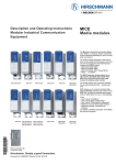
User Manual
Installation
Industrial ETHERNET Switch MICE
MS20/MS30
.
MICE MS20
MICE MS20/MS30
Release 2.0 02/06
MICE MS30
Technical support
[email protected]
The naming of copyrighted trademarks in this manual, even when not specially indicated, should
not be taken to mean that these names may be considered as free in the sense of the trademark
and tradename protection law and hence that they may be freely used by anyone.
© 2006 Hirschmann Automation and Control GmbH
Manuals and software are protected by copyright. All rights reserved. The copying, reproduction,
translation, conversion into any electronic medium or machine scannable form is not permitted,
either in whole or in part. An exception is the preparation of a backup copy of the software for
your own use.
The performance features described here are binding only if they have been expressly
guaranteed in the contract. This publication has been created by Hirschmann Automation and
Control GmbH according to the best of our knowledge. Hirschmann reserves the right to change
the contents of this manual without prior notice. Hirschmann can give no guarantee in respect
of the correctness or accuracy of the details in this publication.
Hirschmann can accept no responsibility for damages, resulting from the use of the network
components or the associated operating software. In addition, we refer to the conditions of use
specified in the license contract.
Printed in Germany (9.2.06)
Hirschmann Automation and Control GmbH
Stuttgarter Straße 45-51
72654 Neckartenzlingen
Tel. +49 1805 141538
039 530-001-02-0206
Content
Safety instructions
4
About this manual
9
Legend
9
1
Device description
10
1.1
Description of the device variants
1.1.1 MS20-... /MS30-... combination options
1.1.2 Number of ports and media
1.1.3 Media modules
1.1.4 MB - 2T expansion module
1.1.5 SFP module
11
13
14
16
20
20
2
Assembly and startup procedure
21
2.1
Device installation
2.1.1 Unpacking and checking
2.1.2 Assembling the media modules
2.1.3 Filling out and attaching the labels
2.1.4 Assembling the SFP modules
2.1.5 Adjusting the DIP switch settings on the basic module
2.1.6 Adjusting the DIP switch settings on the
MICE MM3-2AUI media module (if existent)
2.1.7 Terminal block for supply voltage and signal contact
2.1.8 Connecting the terminal blocks, startup procedure
2.1.9 Assembling the device on the ISO/DIN rail, grounding
2.1.10Connecting the data lines
2.1.11Assembling the MB - 2T expansion module
2.1.12Define the meaning of the display LEDs
21
21
21
22
23
23
24
25
26
26
27
29
29
2.2
Displays
30
2.3
Carrying out basic settings
34
2.4
Disassembling
36
3
Technical data
37
Further support
43
MS20/MS30
Release 2.0 02/06
3
Safety instructions
This manual contains instructions which must be observed to ensure your
own personal safety and to avoid damage to devices and machinery.
U Certified usage
Please observe the following: The device may only be employed for the
purposes described in the catalog and technical description, and only in
conjunction with external devices and components recommended or
approved by Hirschmann. The product can only be operated correctly
and safely if it is transported, stored, installed and assembled properly
and correctly. Furthermore, it must be operated and serviced carefully.
U Supply voltage
The devices are designed for operation with a safety extra-low
voltage.Thus, they may only be connected to the supply voltage connections and to the signal contact with PELV circuits or alternatively SELV
circuits with the voltage restrictions in accordance with IEC/EN 60950.
The supply voltage is electrically isolated from the housing.
V Use only undamaged parts!
V Relevant for North America:
The subject unit is to be suppplied by a Class 2 power source complying with the requirements of the National Electrical Code, table 11(b).
If power is redundant supplied (two individual power sources) the power sources together should comply with the requirements of the National Electrical Code, table 11 (b).
V Relevant for North America:
Use 60/75°C or 75°C copper(CU)wire only.
V Relevant for North America
for devices certified for hazardous locations:
Power, input and output (I/O) wiring must be in accordance with Class
I, Division 2 wiring methods [Article 501-4(b) of the National Electrical
Code, NFPA 70] and in accordance with the authority having
jurisdiction.
U Shielding ground
The shielding ground of the connectable twisted pairs lines is connected
to the front panel as a conductor.
V Beware of possible short circuits when connecting a cable section
with conductive shielding braiding.
4
MS20/MS30
Release 2.0 02/06
U Housing
Only technicians authorized by Hirschmann are permitted to open the
housing.
The lower covering panel of the MICE housing is grounded by the DIN
rail and, as an option, by the separate ground screw.
The switch basic module forms an inseparable unity. By removing the
display and connecting parts, you risk the damage of the switch basic
module.
V Make sure that the electrical installation meets local or nationally applicable safety regulations.
V The ventilation slits must not be covered to ensure free air circulation.
V The distance to the ventilation slots of the housing has to be a minimum of 10 cm.
V Never insert pointed objects (thin screwdrivers, wires, etc.) into the inside of the subrack! Failure to observe this point may result in injuries
caused by electric shocks.
V The device has to be mounted in an upright position (see Fig. 13).
V If installed in a living area or office environment, the device must be
operated exclusively in switch cabinets with fire protection characteristics according to EN 60950.
U Environment
The device may only be operated in the listed maximum surrounding air
temperature range at the listed relative air humidity range (non-condensing).
V The installation location is to be selected so as to ensure compliance
with the climatic limits listed in the Technical Data.
V To be used in a Pollution Degree listed in the Technical Data.
U Qualification requirements for personnel
Qualified personnel as understood in this manual and the warning signs,
are persons who are familiar with the setup, assembly, startup, and operation of this product and are appropriately qualified for their job. This
includes, for example, those persons who have been:
D trained or directed or authorized to switch on and off, to ground and to
label power circuits and devices or systems in accordance with current
safety engineering standards;
D trained or directed in the care and use of appropriate safety equipment
in accordance with the current standards of safety engineering;
D trained in providing first aid.
MS20/MS30
Release 2.0 02/06
5
U General Safety Instructions
This device is electrically operated. Adhere strictly to the safety requirements relating to voltages applied to the device as described in the operating instructions!
Failure to observe the information given in the warnings could result in
serious injury and/or major damage.
V Only personnel that have received appropriate training should operate
this device or work in its immediate vicinity. The personnel must be fully familiar with all of the warnings and maintenance measures in these
operating instructions.
V Correct transport, storage, and assembly as well as careful operation
and maintenance are essential in ensuring safe and reliable operation
of this device.
V Only use undamaged parts!
V These products are only to be used in the manner indicated in this version of the manual.
V Any work that may have to be performed on the electrical installation
should be performed by fully qualified technicians only.
Warning!
LED- or LASER components according to IEC 60825-1 (2001):
CLASS 1 LASER PRODUCT.
LIGHT EMITTING DIODE - CLASS 1 LED PRODUCT.
Warning (MM2 - 2FXP4, MM3 - 4FXP4)
LED LIGHT
DO NOT STARE INTO THE BEAM OR VIEW DIRECTLY
WITH OPTICAL INSTRUMENTS (e.g. lens, microscope).
Failure to observe this warning within a distance of 100 mm
can endanger your eyes. Light is emitted from the optical connections or
from the ends of the optical fibers that are connected to them. Light Emitting Diode CLASS 2M, Wave length 650 nm, Power <2 mW, according to
IEC/CEI 60825-1:2003-10.
U National and international safety regulations
V Make sure that the electrical installation meets local or nationally applicable safety regulations.
6
MS20/MS30
Release 2.0 02/06
U ESD guidelines (MM2 - 2FXP4, MM3 - 4FXP4)
The media modules MM2-2FXP4 and MM3-4FXP4 contain components
highly sensitive to electrostatic fields. These components can be easily
destroyed or have their lives shortened by an electrical field or by a
discharge caused by touching the contacts. You can find more information about devices vulnerable to electrostatic fields in DIN EN 61340-5-1
(2001-08) and DIN EN 61340-5-2 (2002-01).
U Note on the CE marking
The devices comply with the regulations contained in the following
European directives:
89/336/EEC
Directive of the council for standardizing the regulations of member
states on electromagnetic compatibility (changed by RL 91/263/EEC, 92/
31/EEC and 93/68/EEC).
In accordance with the above-named EU directives, the EU conformity
declaration will be at the disposal of the relevant authorities at the following address:
Hirschmann Automation and Control GmbH
Stuttgarter Straße 45-51
D-72654 Neckartenzlingen
Germany
Phone ++49 7127 14 1480
The product can be used in living areas (living area, place of business,
small business) and in industrial areas.
D Interference immunity: EN 61000-6-2:2001
D Emitted interference: EN 55022:1998 + A1 2000 + A2 2003 Class A
Warning!
This is a class A device. This device can cause interference in living
areas, and in this case the operator may be required to take appropriate
measures.
The assembly guidelines provided in these instructions must be strictly
adhered to in order to observe the EMC value limits.
MS20/MS30
Release 2.0 02/06
7
U FCC note:
Appropriate testing has established that this device fulfills the requirements of a class A digital device in line with part 15 of the FCC
regulations.
These requirements are designed to provide sufficient protection against
interference where the device is being used in a business environment.
The device creates and uses high frequencies and can radiate same,
and if it is not installed and used in accordance with this operating
manual, it can cause radio transmission interference. The use of this
device in a living area can also cause interference, and in this case the
user is obliged to cover the costs of removing the interference.
U Recycling note:
After usage, this product must be disposed of properly as electronic
waste in accordance with the current disposal regulations of your county
/ state / country.
8
MS20/MS30
Release 2.0 02/06
About this manual
The following manuals are included as PDF files on the enclosed CD ROM:
D
D
D
D
D
User manual “Installation”
User manual “Basic configuration”
User manual “Redundancy configuration”
Reference manual “Web-based Interface” and
Reference manual “Command Line Interface”
If you use Network Management Software HiVision you have further
opportunities to:
D
D
D
D
D
D
have an event logbook.
configure the “System Location” and “System Name”.
configure the network address range and SNMP parameters.
save the configuration on the Switch.
simultaneous configuration of several Switches.
configure the relevant ports to be displayed red if there is no link state.
Legend
The commendations used in this manual have the following meanings:
D
Listing
V
Work step
U
Subheading
MS20/MS30
Release 2.0 02/06
9
1
Device description
The MS20/MS30 devices consist of a switch with media modules that can be
plugged into it. They allow you to construct switched industrial ETHERNET
networks that conform to the IEEE 802. and 802.3u standards using copper
wires or optical fibers in a bus or ring topology. You can connect terminal devices and other infrastructure components via twisted pair cables, multimode LWL and single-mode LWL. The twisted pair ports support autocrossing, autonegotiation and autopolarity.
MS20
MS30
Basic module
Media module or
slot for media module, No.
1
2
3
4
1
2
3
4
5
The MS20/MS30 devices provide you with a range of switch variants. You
can set up your switch to meet your individual requirements with regard to the
transmission media type, the number of 10/100 Mbit ports you want (8, 16 or
24), the number of 1000 Mbit ports (up to 2), the temperature range, voltage
range, certificates and software variant.
The MS20/MS30 devices are modular network components. They are designed for the special requirements of industrial automation. They meet the
relevant industry standards, provide very high operational reliability, even under extreme conditions, and also long-term reliability and flexibility. The devices operate without fans and have a redundant voltage supply. The
switches are very quickly mounted by snapping them onto a hat rail, which
also automatically contacts the function ground.
The HIPER-Ring redundancy concept enables you to quickly carry out a reconfiguration, and also a simple configuration with only one additional connection. The diagnosis display and the display of the operating parameters
and the large label areas provide a quick overview.
It can be easily managed via a Web browser, via Telnet, with a management
software product (such as F) or locally on the switch (V.24 interface).
10
MS20/MS30
Release 2.0 02/06
Depending on the software you choose, the MS20/MS30 devices provide
you with a large range of functions:
D Redundancy functions
(Rapid Spanning Tree, Redundant Ring Structure, HIPER-Ring,
Redundant Coupling, Link Aggregation, Redundant Power Supply)
D Protection from unauthorized access
D Synchronized system time in the network
D Network load control
D Function diagnosis
D Diagnostics (hardware self-testing)
D Reset
D Priority
D VLAN
D Topology recognition
D Web-based interface
D Command Line Interface - CLI
D SNMP
D 802.1x port authentication
D Real Time Clock (Professional software variant)
The addition, to the MS20/MS30 MICE range, of the RS20/RS30 Open Rail
range of switches, the MACH range of backbone switches, the BAT wireless
transmission system, the EAGLE security system, and products for the LION
control room, provides continuous communication across all levels of the
company.
1.1
Description of the device variants
The industrial ETHERNET series MICE (Modular Industrial Communication
Equipment) consists of a basic switch module and the media modules. These
devices can be managed. A basic module contains all the functions of this
industrial Gerät, with the exception of the interfaces to the LAN that is
connected. Pluggable media modules provide these interfaces. They differ
with regard to the number of interfaces and the media type for connecting
segments. An expansion module enables you to add 2 slots for media
modules to the basic module.
For the sake of simplicity, the basic switch module with various plugged in
media modules will be referred to as MICE in this document.
D The MS20-... device variants are modular switches with up to 8, 16 or 24 *
10/100 Mbit Ethernet ports. You can choose the media for the ports via
the media modules.
MS20/MS30
Release 2.0 02/06
11
D The MS30-... device variants are modular switches with up to 8, 16 or 24 *
10/100 Mbit Ethernet ports and up to 2 additional Gigabit ports (1000 Mbit
Ethernet). You can choose the media for the ports via the media modules.
The devices also provide you with the following options for selecting the
variant you desire:
D Temperature range:
D Standard (0 °C to +60 °C)
D Extended (-40 °C to +70 °C) without conformal coating
D Extended (-40 °C to +70 °C) with conformal coating
D Voltage range:
D 18 to 32 VDC (flatter basic module design)
D 18 to 60 VDC (deeper basic module design)
D Certifications:
D CE, UL
D CE, UL, German Lloyd (GL), IEC 61850 Declaration (Sub Station),
IEEE 1613 (Sub Station), EN 50121-4 Railway (along track)
D CE, UL, German Lloyd (GL), IEC 61850 Declaration (Sub Station),
IEEE 1613 (Sub Station), EN 50121-4 Railway (along track), EN
50155 Declaration (Railway) and ATEX 100a (Hazardous Location)
D Software version: Enhanced or Professional
The devices comply with the specifications of the standards:
ISO/IEC 8802-3u 100BASE-TX/-1000BASE-T,
ISO/IEC 8802-3 100BASE-FX and
ISO/IEC 8802-3 1000BASE-SX/LX.
The basic module of the MICE contains all the function units, such as: switch
function, management function, redundancy function, display control,
voltage connection, management connection, adjustable controls, slots for
media modules.
Family
MS20
MS30
12
Designed for
Larger numbers of ports,
number of 100 Mbit ports desired, temperature range, voltage range, certificates and software variant can be selected
Larger numbers of ports and larger bandwidth requirement,
number of 100/1000 Mbit ports desired, temperature range, voltage range,
certificates and software variant can be selected
MS20/MS30
Release 2.0 02/06
1.1.1
MS20-... /MS30-... combination options
The product designation of your MS20/MS30 device is made from combining
the desired product characteristics in accordance with the following table.
The short designation is in column 3.
Position
1 to 4
Attribute
Produkt
5
6 to 7
- (hyphen)
Number of 10/100 Mbit ports
8 and 9
Number of 1000 Mbit ports
14
Temperature range
15
Voltage range
16
Specifications
Ident.
MS20
MS30
08
16
24
00
02
S
T
E
A
C
A
H
B
17
Software version
E
P
Feature
Modular Switch without gigabit ports
Modular Switch with gigabit ports
8 * 10/100 Mbit Ethernet
16 * 10/100 Mbit Ethernet
24 * 10/100 Mbit Ethernet
0 * 1000 Mbit Ethernet
2 * 1000 Mbit Ethernet
Standard 0 °C to +60 °C
Extended -40 °C to +70 °C
Extended -40 °C to +70 °C, conformal
coating
18 VDC to 32 VDC
18 VDC to 60 VDC
CE, UL
CE, UL, GL, railway (along track),
sub station
CE, UL, GL, railway (along track), sub
station, hazardous location (ATEX),
railway (train)
Enhanced
Professional
Table 1: Combination options of the MS20/MS30 device versions
U Example: MS30-0802SAAE
MS30-: Modular switch with gigabit ports
08: 8 x 100 Mbit Ethernet ports
02: 2 x 1000 Mbit Ethernet ports
S: Temperature range standard (0°C to 60°C)
A: Voltage range 18 VDC to 32 VDC
A: Specifications CE and UL
E: Software version enhanced
MS30- 08 02 S A A E
MS20/MS30
Release 2.0 02/06
13
1.1.2
Number of ports and media
U Device versions with 10/100 Mbit ports
MS20-0800..., MS20-1600..., MS20-2400...
Depending on the variant, the MS20 basic modules provide you with the
following number of slots for media modules and the following maximum
number of connectable network segments:
Basic module
MS20-0800...
MS20-1600...
MS20-2400...
1)
Number of slots for
10/100 Mbit media
modules
2
4
6
Maximum number of connectable 10/100 Mbit
network segments when connecting 4 port media
modules
8
16 1)
24
Expandable to 24 ports with MB2-T expansion module
4 slots for media modules
Switch
basic module MM2-… or MM3-… with 2-4 ports each
MS20-…
Grounding screw
MS20-0800...
Terminal block,
V.24 port,
USB port,
DIP switch
MS20-1600...
Fig. 1:
14
Key for
display
status
LEDs
device status,
display status
MS20-2400...
Overview interfaces, display elements and controls of the MS20 -...
MS20/MS30
Release 2.0 02/06
MICE MS20/30
switch basic module
with 18 to 60 VDC
voltage range
MICE MS20/30
switch basic module
with 18 to 32 VDC
voltage range
V.24 port
USB port
terminal block
(power 1)
DIP switch
V.24 port
USB port
DIP switch
terminal block
(power 2)
Fig. 2:
terminal block (power 1)
terminal block (power 2)
Interfaces of the MS20-... and MS30-... on the bottom of the device
U Device versions with 1000 Mbit and 10/100 Mbit ports
MS30-0802..., MS30-1602..., MS30-2402...
Depending on the model, the MS30 basic modules offer you the
following number of slots for media modules and the following maximum
amount of connectable network segments:
Basic module
MS30-0802...
MS30-1602...
MS30-2402...
1)
Number of
slots for
10/100 Mbit
media
modules
2
4
6
Number of
slots for
1000 Mbit
media
modules
1
1
1
Maximum number of
connectable 10/100
Mbit network segments
when connecting 4 port
media modules
8
16 1)
24
Maximum amount of
connectable 1000 Mbit
network segments
2
2
2
Expandable to 24 ports with MB2-T expansion module
MS20/MS30
Release 2.0 02/06
15
4 slots for media modules
Switch
Slot for
SFP module basic module MM2-… or MM3-… with 2-4 ports each
MM4-TX/SFP MS30-…
Grounding screw
MS30-0800...
Terminal block,
V.24 port,
USB port,
DIP switch
Key for
display
status
LEDs
device status,
display status
MS30-1600...
Fig. 3:
MS30-2400...
Overview interfaces, display elements and controls of the MS30
The figure “Interfaces of the MS20-... and MS30-... on the bottom of the device” on page 15 illustrates the interfaces on the bottom of the MS30 device.
1.1.3
Media modules
The MICE media modules form the interface of the device to the LAN.
They can be attached in the
D Basic module MS20-...
D Basic module MS30-...
They differ with regard to the number of interfaces and media type. The
various interfaces of the MICE media modules offer you the following interface-specific functions:
D Specific functions of the TP/TX interface
D Link Control
D Auto Polarity Exchange
D Autonegotiation
D Autocrossing (it does not matter whether you connect devices using a
cross-over or straight cable)
D Specific functions of the F/O interface
D Link control
D Transceiver- (AUI-) specific functions
16
MS20/MS30
Release 2.0 02/06
D
D
D
D
Collision detection
Collision Test (SQE)
Jabber-Control
DTEPower monitor
U MICE 2000 media modules
MICE 2000
media modules
Module type
F/O port
TP ports multiAUI port 10/100 mode
10 MBit/
s
F/O port
multimode
POF
100
MBit/s
MM2 - 4TX1 (- EEC)
MM2 - 2FLM4
MM2 - 2FXP4
MM2 - 4FXM3
MM2 - 2FXM3 / 2TX1
MM2 - 2FXM2
MM2 - 2FXS2
–
–
–
–
–
–
–
–
–
2, ST
–
–
–
–
4, RJ45
–
–
–
2, RJ45
–
–
–
2, ST
–
–
–
–
–
F/O port
singlemode
1300
nm,
100
MBit/s
–
–
–
–
–
–
4, MTRJ –
2, MTRJ –
2, DSC –
–
2, DSC
F/O port
multimode
100
MBit/s
F/O port
singlemode
1550
nm,
100
MBit/s
–
–
–
–
–
–
–
Table 2: Media connectors each MICE 2000 media module (number and kind)
Port 1
Port 2
Port 3
Port 4
Fig. 4:
Port assignment
MS20/MS30
Release 2.0 02/06
17
U MICE 3000 media modules
MICE 3000
media modules
Module type
F/O port
TP ports multiAUI port 10/100 mode
10
MBit/s
F/O port
multimode
POF
100
MBit/s
F/O port
multimode
100
MBit/s
MM3-2AUI
MM3-4TX5
MM3-4TX1-RT
MM3-2FLM4/2TX1-RT
MM3-4FLM4
MM3-4FXP4
MM3-1FXM2/3TX1
MM3-2FXM2/2TX1(-EEC)
MM3-2FXM2/2TX1-RT
MM3-2FXM4/2TX1
MM3-4FXM2
MM3-4FXM4
MM3-1FXS2/3TX1(-EEC)
MM3-2FXS2/2TX1
MM3-2FXS2/2TX1-RT
MM3-4FXS2
MM3-1FXL2/3TX1
2,Sub-D
–
–
–
–
–
–
–
–
–
–
–
–
–
–
–
–
–
–
–
–
–
4, ST
–
–
–
–
–
–
–
–
–
–
–
–
–
–
–
–
–
1, DSC
2, DSC
2, DSC
2, ST
4, DSC
4, ST
–
–
–
–
–
–
4, M12
4, RJ45
2, RJ45
–
–
3, RJ45
2, RJ45
2, RJ45
2, RJ45
–
–
3, RJ45
2, RJ45
2, RJ45
–
3, RJ45
–
–
–
2, ST
4, ST
–
–
–
–
–
–
–
–
–
–
–
–
F/O port
singlemode
1300
nm,
100
MBit/s
–
–
–
–
–
–
–
–
–
–
–
–
1, DSC
2, DSC
2, DSC
4, DSC
–
F/O port
singlemode
1550
nm,
100
MBit/s
–
–
–
–
–
–
–
–
–
–
–
–
–
–
–
–
1, DSC
Table 3: Media connectors each MICE 3000 media module (number and kind)
Port 1
Port 2
Port 3
Port 4
Fig. 5:
18
Port assignment
MS20/MS30
Release 2.0 02/06
U MICE 4000 media modules
The 2-port media module MM4 - 2TX/SFP has two TP interfaces and two
sockets for Hirschmann SFP modules.
The 4-port media module MM4 - 4TX/SFP can also be used in the MS20/
MS30. It has four TP interfaces and four sockets for Hirschmann SFP modules. The MS30 gigabit slot (slot on the left side of the switch basic module) provides two ports.
Every slot allows you to replace a TP interface by a F/O interface using a
SFP module. Inserting the SFP module deactivates the corresponding TP
interface.
Note: Only use SFP modules from Hirschmann.
MICE 4000 media modules
Module type
MM4 - 2TX/SFP
MM4 - 4TX/SFP
TP ports
10/100/1000
2, RJ45
4, RJ45
SFP ports
alternativ to TP ports
2
4
Table 4: Media connectors each MICE 4000 media module (number and kind)
Port 1
Port 2
Port 3
Port 4
Port 1*
Port 3*
Port 2*
Port 4*
Port 1 to 4: SPF ports, alternativ to
port 1* to 4* (TP ports)
Fig. 6:
Port assignment
MS20/MS30
Release 2.0 02/06
19
1.1.4
MB - 2T expansion module
The MB-2T expansion module allows you to add 2 slots to the MICE
MS20-1600 / MS30-1602 basic modules for installing media modules.
Fig. 7:
MB - 2T expansion module
1.1.5
SFP module
SFP modules are optical transceivers. SFP stands for Small Form-factor
Pluggable and is often named mini-GBIC (GigaBit Interface Converter).
They are plugged onto the special ports of the MICE 4000 media modules
MM4-2TX/SFP (or MM4-4TX/SFP) to provide a F/O port. Inserting the SFP
module deactivates the corresponding TP interface.
Module type
M-SFP-SX/LC
M-SFP-LX/LC
M-SFP-LH/LC
M-SFP-LH+/LC
Transmission
850 nm multimode
1330 nm multimode
1330 nm singlemode
Long haul
Long haul +
Expansion
0,55 km
0,55 km
20 km
8-72 km
60-120 km
Connector
LC
LC
LC
LC
LC
Table 5: SFP modules
20
MS20/MS30
Release 2.0 02/06
2
Assembly and startup procedure
The Industrial ETHERNET Modular Industrial Communication Equipment
(MICE) Family has been developed for practical application in a harsh industrial environment. Accordingly, the installation process has been kept simple.
On delivery, the device is ready for operation.
The following procedure is appropriate for assembly:
D Unpacking and checking
D Assembling the media modules
D Filling out and attaching the labels
D Assembling the SFP modules
D Adjusting the DIP switch settings on the basic module
D Adjusting the DIP switch settings on the MICE MM3-2AUI media module
(if existent)
D Connecting the terminal block for supply voltage and signal contact,
connecting the supply voltage
D Assembling the terminal block, startup procedure
D Assembling the device on the ISO/DIN rail, grounding
D Connecting the data lines
D Assembling the expansion module
2.1
Device installation
2.1.1
Unpacking and checking
V Check whether the package was delivered complete,
see “Scope of delivery” on page 41.
V Check the individual parts for transport damage.
2.1.2
Assembling the media modules
On delivery, the device is ready for operation. Media modules can be assembled and disassembled during running operation.
V To fasten a media module, first remove the protective cap over the plug.
V Plug the media module onto the plug.
V Tighten the 4 screws on the corners of the media module.
V Fit the media modules one after the other from the left to the right.
V Check whether the switch pre-setting suits your requirements.
MS20/MS30
Release 2.0 02/06
21
2.1.3
Filling out and attaching the labels
The labels included in the delivery help you to structure your network
installation clearly.
The large label areas enable you to designate the modules and uniquely assign the devices to be connected. You can print them, write on them and exchange them at any time.
Fig. 8:
Attaching the labels
Lable on the basic module:
- Name of the module
- MAC address of the device
- IP address of the device
- Other entries on your demand
Lables on the media modules:
- Name of the module
- Port assignment of the
module each port
Fig. 9:
Labels for basic module and media modules
V Attach the labels included in the delivery to the basic module and the
media modules as required.
22
MS20/MS30
Release 2.0 02/06
2.1.4
Assembling the SFP modules
V To fasten a SFP module, first remove the protective cap over the socket.
V Insert the SFP module with the closed lock into the socket until you hear
it snap in.
Note: Only use SFP modules from Hirschmann.
Fig. 10:
Installation SFP module
2.1.5
Adjusting the DIP switch settings on the basic module
The 4-pin DIP switch in the bottom panel of the basic module provides you
with the following options:
DIP switch
RM (Redundancy
Manager) 2)
Function
When the HIPER-Ring function is
switched on, you can switch the RM
(Redundancy Manager) function on and
off (see “User Manual - Redundancy Configuration”).
1)
Selecting the ports for the HIPER-Ring.
Ring port
MS30: In the ON position, ports 1 and 2 in
module 2 are for connecting the HIPERRing.
MS20: In the ON position, port 1 from
modules 1 and 2 are for connecting the
HIPER-Ring.
2)
Stand-by
With the redundant coupling of rings, you
assign the redundancy function to the
MICE in the redundant line (see “User
Manual - Redundancy Configuration”).
Software Configu- Give the software configuration priority
ration / DIP Confi- ahead of the DIP switch position. In this
guration
case, the other switch positions are
meaningless.
MS20/MS30
Release 2.0 02/06
State of delivery
position OFF (RM function
not active)
position OFF (ports 1 and 2
of module 1 are for connecting the HIPER-Ring)
position OFF (normal
function)
position OFF (software
configuration has priority)
23
1)
You use the “Ringport” switch on the 4-pin DIP switch to select the ring ports for the
HIPER-Ring:
MICE
device
MS20
MS20
MS30
MS30
DIP switch
“Ring-Port”
OFF
ON
OFF
ON
Ring ports for HIPER-Ring
module 1/ port 1 and module 1/ port 2
module 1/ port 1 and module 2/ port 1
module 1/ port 1 and module 1/ port 2
module 2/ port 1 and module 2/ port 2
2)
You use the “RM” and “Stand-by” switches on the 4-pin DIP switch to switch the following
functions on and off:
OFF
Switch
“Stand
by”
OFF
Ring
redundancy
an
RedunRing
dancy
coupling Manager
off
off
ON
OFF
on
off
on
OFF
ON
on
on
off
ON
ON
off
off
off
Switch
“RM”
OFF
Ring
port
see
above
see
above
see
above
Control port
Coupling port
module 1/
port 3 (MS20)
module 2/
port 3 (MS30)
module 1/
port 4 (MS20)
module 2/
port 4 (MS30)
ON
1 Redundancy Manager (RM)
2 Ring port
3 Stand-by
4 Configuration
Fig. 11:
4-pin DIP switch on the MICE MS20-.../MS30-... basic module
V Check whether the switch default settings match your requirements
before starting the device.
2.1.6
Adjusting the DIP switch settings on the
MICE MM3-2AUI media module (if existent)
With the 3-pin DIP switch in the lower panel of the MM3 -2AUI media module,
you enter settings for the SQE test function and for monitoring the DTE
voltage.
Note: Before starting operation, check whether the device in question
operates the transceiver with or without an SQE test.
V Before starting operation of the device, check whether the default settings
of the DIP switch correspond to your requirements.
24
MS20/MS30
Release 2.0 02/06
2.1.7
Terminal block for supply voltage and signal contact
The supply voltage and the signal contacts are connected via a 4-pin terminal
block with snap locking.
U Supply voltage
The supply voltage can be connected redundantly. Both inputs are
uncoupled. With redundant supply, the transformer supplies the device
alone with the higher output voltage. The supply voltage is electrically
isolated from the housing.
Note: With non-redundant supply of the mains voltage, the device reports
a power failure. You can prevent this message by applying the supply
voltage over the two inputs or by changing the configuration via management.
U Signal contacts
D The signal contacts monitor proper functioning of the device, thus enabling remote diagnostics. You can specify the type of function monitoring in the Management.
D You can also use the Management to set the signal contact manually
and thus control external devices.
A break in contact is reported via the potential-free signal contact (relay
contact, closed circuit):
D The failure of at least one of the two supply voltages (supply voltage
1 or 2 < 18 V).
D A continuous malfunction in the device (internal 3.3 VDC voltage).
D The defective link status of at least one port. With the device, the indication of link status can be masked by the management for each port.
Link status is not monitored in the delivery condition.
D The loss of Redundancy guarantee.
D Error during self-test.
The following conditions are reported in stand-by mode
D Control cable disrupted
D Control cable shorted
D Partner device is in stand-by mode
The following conditions are reported in normal mode:
D Control cable shorted
D Partner device is in normal mode
MS20/MS30
Release 2.0 02/06
25
The following condition is reported in RM mode additionally:
D Ring redundancy guaranteed. Ring redundancy is not monitored in the
delivery condition.
2.1.8
Connecting the terminal blocks, startup procedure
V Pull the terminal blocks off the device and connect the power supply
and signal lines.
MICE MS20/30
switch basic module
with 18 to 60 VDC
voltage range
MICE MS20/30
switch basic module
with 18 to 32 VDC
voltage range
Fig. 12:
Power/signal contact 1:
1 = +24 V (P1)
2= 0V
3,4 = Relay 1
Power/signal contact 1:
1 = +24 V (P1)
2= 0V
3,4 = Relay 1
Power/signal contact 2:
1 = +24 V (P2)
2= 0V
3,4 = Relay 2
Power/signal contact 2:
1 = +24 V (P2)
2= 0V
3,4 = Relay 2
Pin assignment of the 4-pin signal contact
V Mount the terminal block for the supply voltage and the signal contact on
the front of the device. Make sure that the snap lock snaps into place.
By connecting the supply voltage at the terminal block, you start the
operation of the device.
2.1.9
Assembling the device on the ISO/DIN rail, grounding
V You mount the device on a 35 mm hat rail according to DIN EN 60175.
V Attach the upper snap-in guide of the device into the hat rail and press it
down against the DIN rail until it snaps into place.
Note: The shielding ground of the connectable twisted pair lines is connected
to the lower panel as a conductor.
26
MS20/MS30
Release 2.0 02/06
Fig. 13:
Assembly
U Grounding
The grounding of the lower panel of the housing of the device is effected
with the hat rail and, optionally, with the separate ground screw (see Fig.
“Overview interfaces, display elements and controls of the MS20 -...” on
page 14).
2.1.10 Connecting the data lines
U 10/100 Mbit/s twisted pair connection
10/100 Mbit/s ports (RJ45 or M12 sockets) enable the connection of terminal devices or independent network segments in compliance with the
IEEE 802.3 100BASE-TX / 10BASE-T standards. These ports support:
D autonegotiation
D autopolarity
D autocrossing (when autonegotiation is switched on)
D 100 Mbit/s half duplex mode, 100 Mbit/s full duplex mode
D 10 Mbit/s half duplex mode, 10 Mbit/s full duplex mode
State on delivery: autonegotiation is activated with exception of the
HIPER-Ring ports: 100 Mbit/s full duplex.
The socket housings are electrically connected to the lower covering.
MS20/MS30
Release 2.0 02/06
27
n.c.
n.c.
TDn.c.
n.c.
TD+
RDRD+
Fig. 14:
Fig. 15:
Pin 8
Pin 7
Pin 6
Pin 5
Pin 4
Pin 3
Pin 2
Pin 1
Pin assignment of a TP/TX interface in MDI-X mode, RJ45 socket
TD+
1
2
RD+
RD-
4
3
TD-
Pin assignment of a TP/TX interface, M12 socket
U 10/100/1000 Mbit/s twisted pair connection
1000 Mbit/s twisted pair connection 1000 MBit/s twisted pair ports (RJ45
sockets) enable the connection of terminal devices or independent network segments in compliance with the IEEE 802-3, 2000 Edition
1000BASE-T standard. These ports support:
D autonegotiation
D autopolarity
D autocrossing (when autonegotiation is switched on)
D 1000 Mbit/s full duplex
D 100 Mbit/s half duplex, 100 Mbit/s full duplex,
D 10 Mbit/s half duplex, 10 Mbit/s full duplex.
State on delivery: autonegotiation.
The socket housing is electrically connected to the front panel.
The pin assignment corresponds to MDI-X.
BI_DCBI_DC+
BI_DABI_DDBI_DD+
BI_DA+
BI_DBBI_DB+
Fig. 16:
28
Pin 8
Pin 7
Pin 6
Pin 5
Pin 4
Pin 3
Pin 2
Pin 1
Pin assignment of a 1000 MBit/s twisted pair interface
MS20/MS30
Release 2.0 02/06
U 100 Mbit/s F/O connection
100 MBit/s F/O ports (MTRJ-, ST- or DSC) enable the connection of terminal devices or independent network segments in compliance with the
IEEE 802.3 100BASE-FX standard. These ports support:
D full and half duplex mode
State on delivery: full duplex.
Note: Make sure, that you conncet LH ports only to LH ports, SM ports
only to SM ports and MM ports only to MM ports.
U 1 Gbit/s F/O connection
1 Gbit/s F/O ports (LC sockets) enable the connection of terminal
devices or independent network segments in compliance with the IEEE
802.3-2000 (ISO/IEC 8802-3:2000) 1000BASE-SX or 1000BASE-LX
standard. These ports support:
D autonegotiation,
D full duplex mode
State on delivery: autonegotiation.
Note: Make sure, that you conncet LH ports only to LH ports, SX ports
only to SX ports and LX ports only to LX ports.
U AUI connection
AUI ports (Attachment Unit Interface) enable you to connect a terminal
device via an AUI cable in accordance with IEEE 802.3-2002.
These ports support:
D SQE test
D DTEPower monitor
State on delivery: both functions not enabled.
The housing of the Sub-D plug is electrically isolated from the lower
panel of the device.
shielding CO
n.c.
GND
output DI-A
shielding DI
input DO-A
output CI-A
shielding CI
Fig. 17:
Pin 8
Pin 7
Pin 6
Pin 5
Pin 4
Pin 3
Pin 2
Pin 1
Pin 15
Pin 14
Pin 13
Pin 12
Pin 11
Pin 10
Pin 9
n.c.
Schirmung 12 V
shielding 12 V
output DI-B
shielding DO
input DO-B
output CI-B
Pin assignment of the AUI interface
Connect the ports of the media modules plugged into the basic module
as required in order to set up your industrial ETHERNET or expand your
existing network.
V Connect the data lines according to your requirements.
MS20/MS30
Release 2.0 02/06
29
2.1.11 Assembling the MB - 2T expansion module
The expansion module MB-2T allows you to add 2 slots to the MS20-1600
and MS30-1602 basic modules for installing media modules. The MB-2T
expansion module can be installed while in running operation.
V On the right side of the basic module, loosen the screw at the top and at
the bottom (1-3 revolutions).
V Remove the side cover.
V If you have not yet done so, mount the basic module onto the DIN rail.
V Slide the MB2T expansion module on the DIN rail toward the basic
module until the modules plug into each other.
V On the basic module, tighten the screws at the top and at the bottom.
2.1.12 Define the meaning of the display LEDs
You use the “SELECT” button on the basic module to define the meaning of
the LEDs of the media modules. You press the button to switch to the next
display meaning. The display status LEDs of the basic module show the current meaning of the port LEDs of the media modules.
Display LEDs
“SELECT” key
Fig. 18:
“SELECT” key on the MICE basic modules
2.2
Displays
After applying the operating voltage, the software starts and initializes itself.
The device then performs a selftest. Various LEDs light up in the process.
The process lasts approximately 60 seconds.
30
MS20/MS30
Release 2.0 02/06
Device status
Display status
Port status
U Device status
These LED's provide information about conditions which affect the operation of the whole device.
P- Power (green LED)
lit green
not lit
P1 - Power 1 (green LED)
lit green
not lit
P2 - Power 2 (green LED)
lit green
not lit
RM - Redundancy Manager
(green/yellow LED)
lit green
lit yellow
not not
flashes green
RUN - BOOT/RUN
(green LED)
lit green
flashes green
not lit
RL1 - Relay 1, signal contact
(red/yellow LED)
lit red
lit yellow
not lit
RL2 - Relay 2, signal contact
(red/yellow LED)
lit red
lit yellow
not lit
MS20/MS30
Release 2.0 02/06
Meaning
internal supply voltage on
internal supply voltage too low
Meaning
supply voltage 1 on
supply voltage 1 under 18 V
Meaning
supply voltage 2 on
supply voltage 2 under 18 V
Meaning
RM function active, redundant port not active
RM function active, redundant Port active
RM function not active
Incorrect configuration of the HIPER-Ring (e.g., the
Ring is not connected to the ring port).
Meaning
System is ready for operation
System booting
System in reset state
Meaning
The signal contact 1 is open, i.e. it indicates an error
The signal contact 1 is open, the “manual setting” is
active
The signal contact 1 is closed, i.e. it does not indicate
an error
Meaning
The signal contact 1 is open, i.e. it indicates an error
The signal contact 1 is open, the “manual setting” is
active
The signal contact 1 is closed, i.e. it does not indicate
an error
31
RUN, 1 - Display saving
operations of the
AutoConfiguration Adapter
ACA
blinking alternatively:
blinking synchronously twice
per second:
blinking synchronously once
per second:
Meaning
Error during memory operation.
Loading the ACA configuration.
Saving the configuration in the ACA .
If the manual adjustment is active on the signal contact, then the error
display is independent of the setting of the signal contact.
U Display status
Each media module has one LED per port. The meaning of these port
status LEDs depends on the setting on the basic module. The display
meaning can be set with the “SELECT” button on the basic module.
V Press the button approximately two seconds to continue switching the
meaning of the display. If the button is not pressed for approximately
20 seconds, the display status changes to “L/D.”
L/D - Data, Link status
(green LED)
lit green
Meaning
The port LEDs of the media modules display the
connection status.
FDX - Full duplex (green LED) Meaning
lit green
The port LEDs of the media modules display the
connection type, full or half duplex.
1000 - 10/100/1000 Mbit/s
Meaning
(green LED)
lit green
The port LEDs of the media modules indicate the
transmission rate.
AN - Autonegotiation
Meaning
(green LED)
lit green
The port LEDs of the media modules indicate the port
configuration type
RING - Ring port (green LED) Meaning
lit green
The port LEDs of the media modules indicate the
HIPER-Ring assignment.
STBY - Stand by (green LED) Meaning
lit green
The port LEDs of the media modules indicate the assignment to a redundant coupling of network segments.
TEST - LED test (green LED) Meaning
lit green
The test of the LEDs status, display status and port
status is active.
The LEDs P1/P2 light green.
The status LED “RM” blinks green/yellow.
The status LEDs “RELAY1/RELAY2” blinks yellow/red.
The display status LEDs blink green.
The port status LEDs of the media modules blink green/
yellow.
32
MS20/MS30
Release 2.0 02/06
TP - Twisted pair / fiber optic
(green LED)
lit green
All display status-LEDs
(green LEDs)
Running licht
2, 3 (green LEDs)
Meaning
The port LEDs of the media modules display the media
type.
Meaning
Initialization phase after restart.
Meaning
Service LEDs
U Portstatus
These LEDs display port-related information. Set the contents of the
information with the button on the basic module. (see “Display status” on
page 32).
1 to 4 - Data, link status (green/
Meaning
yellow LED)
not lit
no valid connection
no DTE voltage at the port (for MM3-2AUI).
lit green
valid connection
DTE voltage at the port (for MM3-2AUI)
flashes green (1 time per
port is switched to stand-by (port 1).
second)
flashes green (3 times per
port is disabled
second)
flashes yellow
data reception at the specific port
1 to 4 - FDX (green/yellow
Meaning
LED)
not lit
Half duplex is active
lit green
Full duplex is active
1 to 4 – 1000
Meaning
(green/yellow LED)
not lit
10 Mbit/s is active.
lit green
100 Mbit/s is active.
lit yellow
1000 Mbit/s is active.
1 to 4 – AUTONEG
Meaning
(green/yellow LED)
lit green
Autonegotiation is active.
1 to 4 – RING PORT
Meaning
(green/yellow LED)
lit green
This port belongs to the HIPER-Ring
1 to 4 – STAND-BY
Meaning
(green/yellow LED)
lit green
Connection port for the data line
lit yellow
Connection port for the control line
flashes green/yellow
no Stand-by partner existing
TP/FO – Twisted pair / fiber
Meaning
optic (green/yellow LED)
lit green
The port LEDs of the media modules display twisted
pair ports
lit yellow
The port LEDs of the media modules display F/O ports
MS20/MS30
Release 2.0 02/06
33
1 to 4 – LED TEST
(green/yellow LED)
not lit
flashes green/yellow
2.3
Meaning
LED defective.
LED test is active.
Carrying out basic settings
IP addresses must be entered when the device is installed for the first time.
The device provides 6 options for configuring the IP addresses:
D
D
D
D
D
D
Entry via the V.24 connection.
Entry by HiDiscovery protocol
Configuration via BOOTP
Configuration via DHCP
Configuration via DHCP Option 82
The AutoConfiguration Adapter
You will find a detailed description of the configuration in the “Basic
Configuration User Manual” on the CD-ROM.
U State of delivery
D IP address: The device looks for the IP address using DHCP
D Password for management:
user, password: public (read only)
admin, password: private (read and write)
D V.24 data rate: 9.600 baud
D Ring redundancy: on
Ring ports on 100 Mbit full duplex or 1000 Mbit autonegotiation
D Ethernet ports: Link status is not evaluated (signal contact)
D Optical 100 Mbit ports: 100 Mbit full duplex
All other ports: autonegotiation
D Redundancy manager switched off
D Stand-by coupling off
U USB interface
The USB socket offers an interface for the local connection of an AutoConfiguration Adapter ACA 21-USB. It is a device for saving/loading the
configuration and for loading the software.
Pin number
1
2
3
4
34
Signal name
VCC
- Data
+ Data
Ground
MS20/MS30
Release 2.0 02/06
U V.24 interface (external management)
A serial interface is provided on the RJ11 socket (V.24 interface) for the
local connection of an external management station (VT100 terminal or
PC with appropriate terminal emulation) or an AutoConfiguration Adapter
ACA 11. This makes it possible to establish a connection to the Command Line Interface CLI and to the system monitor.
VT 100 terminal settings
Speed
Data
Stopbit
Handshake
Parity
9.600 baud
8 bit
1 bit
off
none
The socket housing is electrically connected to the front cover of the
device.
The V.24 interface is electrically connected to the supply voltage.
RJ11
DB9
Pin 5
Pin 8
Pin 6
Pin 1
Pin 1
CTS
n.c.
TX
GND
RX
RTS
Fig. 19:
1
2
3
4
5
6
2
3
5
Pin assignment of the V24 interface
Note: In chapter “Technical data” on page 37 ff you find the order number
for the terminal access cable which is to be ordered separately.
MS20/MS30
Release 2.0 02/06
35
2.4
Disassembling
U Disassembling the device
V In order to remove the device from the DIN rail, press it downward and
pull it out from under the DIN rail.
Fig. 20:
Disassembling the device
U Disassembling the SFP modules
V Pull the SFP module on the opened lock out off the socket.
V Close the socket with the protective cap.
Fig. 21:
36
Disassembling the SFP module
MS20/MS30
Release 2.0 02/06
3
Technical data
U General data
Dimensions
WxHxD
Weight
Voltage supply
MS20-0800...
MS30-0802...
MS20-1600...
MS30-1602...
MS20-2400...
MS30-2402...
MS20-0800...
MS30-0802...
MS20-1600...
MS30-1602...
MS20-2400...
MS30-2402...
Operating voltage
Overload current
protection at input
Isolation voltage
between operating
voltage and housing
Surrounding
Storage temperature
(surrounding air)
Humidity
Atmospheric pressure
Operating temperature
Pollution degree
Protection types
1)
Standard
Extended
Laser protection
Protection types
125 mm x 133 mm x 100 mm (140 mm 1) )
163 mm x 133 mm x 100 mm (140 mm 1) )
202 mm x 133 mm x 100 mm (140 mm 1) )
240 mm x 133 mm x 100 mm (140 mm 1) )
278 mm x 133 mm x 100 mm (140 mm 1) )
316 mm x 133 mm x 100 mm (140 mm 1) )
610 g (700 g 1) )
740 g (830 g 1) )
880 g (970 g 1) )
1010 g (1100 g 1) )
1030 g (1120 g 1) )
1160 g (1250 g 1) )
18 to 32 V DC (voltage range A) or
18 to 60 V DC (voltage range C)
safety extra-low voltage (SELV/PELV), redundant
inputs decoupled. Relevant for North America:
Nec Class 2 power source 5 A maximum.
non-changeable fuse
800 V
Standard: -40 °C to +70 °C
Extended: -40 °C to +85 °C
10% to 95% (non condensing)
up to 2.000 m (795 hPa), higher altitudes on
demand
0 °C to +60 °C
-40 °C to +70 °C
2
Class 1 conforming to EN 60825-1 (2001)
IP 20
At 48 VDC power supply (voltage range C (18...60 VDC),
see table “Combination options of the MS20/MS30 device versions” on page 13)
U EMV and stability
EMV interference
proof
EN 61000-4-2
EN 61000-4-3
MS20/MS30
Release 2.0 02/06
Discharge of static electricity
Contact discharge: test level 3
Air discharge: test level 3
Electromagnetic fields
Test level 3 (80 - 2000 MHz)
A 1)
B 1)
4 kV
8 KV
8 kV
15 kV
10 V/m 20 V/m
37
EMV interference
proof
EN 61000-4-4
EN 61000-4-5
EN 61000-4-6
EN 61000-4-9
Fast transients (burst), test level 3, x
- Power line
- Data line
Surge voltage
- Power line, line/line: test level 2
- Power line, line/earth: test level 3
- Data line: test level 3
Cable-based RF faults, test level 3
10 kHz - 150 kHz
150 kHz - 80 MHz
Impulse-shaped magnetic fields; test level 4
EMV emitted immunity
EN 55022
Class A
FCC 47 CFR Part 15 Class A
Germanischer Lloyd
Rules for Classification and Construction VI - 7 - 3
Part 1, Ed. 2001
Stability
Vibration
IEC 60068-2-6 Test FC, testing level in line with IEC
61131-2
Germanischer Lloyd Guidelines for the Performance
of Type Tests Part 1
IEC 870-2-2 Table 3 Normal Installation in line with
EN61850-3
Shock
IEC 60068-2-27 Test Ea, testing level in line with IEC
61131-2
IEC 870-2-2 Table 3 Normal Installation in line with
EN61850-3
1)
A 1)
B 1)
2 kV
1 kV
4 kV
4 kV
0,5 kV 1 kV
1 kV
2 kV
1 kV
2 kV
3V
10 V
-
3V
10 V
300
A/m
Yes
Yes
-
Yes
Yes
Yes
Yes
Yes
-
Yes
-
Yes
Yes
Yes
-
Yes
Product code A: Certification = CE, UL
Product code B: Certification = CE, UL, GL, Railway, Sub Station, see
“Combination options of the MS20/MS30 device versions” on page 13
U Network size
AUI port
Length of a AUI cable
50 m maximum
Table 6: AUI port
Length of a twisted pair segment
100 m approx.
cat5e cable with 1000BASE-TX
Table 7: TP port 10BASE-T / 100BASE-TX / 1000BASE-T
38
MS20/MS30
Release 2.0 02/06
Product
code
-M2, -M4
-M2, -M4
-S2
-L2
Wave
length
MM 1300 nm
MM 1300 nm
SM 1300 nm
LH 1550 nm
Fiber
System
attenuation
50/125 µm 0-8 dB
62,5/125 µm 0-11 dB
9/125 µm
0-16 dB
9/125 µm
7-29 dB
Expansion Fiber data
0-5 km
0-4 km
0-30 km
24-86 km
1.0 dB/km, 800 MHz*km
1.0 dB/km, 500 MHz*km
0.4 dB/km; 3,5 ps/(nm*km)
0.3 dB/km; 19 ps/(nm*km)
Table 8: F/O port 100BASE-FX
Product
code
-SX/LC
-LX/LC
-SX/LC
-LX/LC
-LX/LC
-LH/LC
-LH+/LC
MM
SM
MM
SM
SM
LH
LH
Wave
length
850 nm
1310 nm 1)
850 nm
1310 nm 1)
1310 nm 1)
1550 nm
1550 nm
Fiber
System
attenuation
50/125 µm 0-7,5 dB
50/125 µm 0-11 dB
62,5/125 µm 0-7,5 dB
62,5/125 µm 0-11 dB
9/125 µm
0-11 dB
9/125 µm
6-22 dB
9/125 µm
15-32 dB
Expansion Fiber data
0-550 m
0-550 m
0-275 m
0-550 m
0-20 km
8-72 km
60-120 km
1.0 dB/km, 800 MHz*km
1.0 dB/km, 800 MHz*km
1.0 dB/km, 500 MHz*km
1.0 dB/km, 500 MHz*km
0.4 dB/km; 3,5 ps/(nm*km)
0.25 dB/km; 19 ps/(nm*km)
0.25 dB/km; 19 ps/(nm*km)
Table 9: F/O port 1000BASE-FX
MM = multimode
SM = singlemode
LH = singlemode longhaul
1)
with F/O adapter in line with IEEE 802.3-2002 clause 38 (single-mode fiber offset-launch mode
conditioning patch cord)
U Power consumption/power output , temperature range
and order numbers
Order numbers of the MICE basic modules see table “Combination
options of the MS20/MS30 device versions” on page 13.
Basic module
MS20-0800S...
MS20-0800E...
MS30-0802S...
MS30-0802E...
MS20-1600S...
MS20-1600E...
MS30-1602S...
MS30-1602E...
MS20-2400S...
MS20-2400E...
MS30-2402S...
MS30-2402E...
MS20/MS30
Release 2.0 02/06
Operating
temperature,
surrounding air
0 °C to +60 °C
-40 °C to +70 °C
0 °C to +60 °C
-40 °C to +70 °C
0 °C to +60 °C
-40 °C to +70 °C
0 °C to +60 °C
-40 °C to +70 °C
0 °C to +60 °C
-40 °C to +70 °C
0 °C to +60 °C
-40 °C to +70 °C
Basic module
MS20-0800...A...
MS20-0800...C...
MS30-0802...A...
MS30-0802...C...
MS20-1600...A...
MS20-1600...C...
MS30-1602...A...
MS30-1602...C...
MS20-2400...A...
MS20-2400...C...
MS30-2402...A...
MS30-2402...C...
Power
consumption
5.0 W
7.4 W
5.6 W
8.6 W
12.0 W
15.6 W
12.6 W
16.8 W
12.0 W
16.8 W
12.6 W
18.0 W
Power output Operating
voltage
17.1 Btu (IT)/h
25.4 Btu (IT)/h
19.2 Btu (IT)/h
29.6 Btu (IT)/h
40.0 Btu (IT)/h
52.5 Btu (IT)/h
41.1 Btu (IT)/h
56.7 Btu (IT)/h
40.0 Btu (IT)/h
56.7 Btu (IT)/h
42.1 Btu (IT)/h
60.9 Btu (IT)/h
18...32 VDC
18...60 VDC
18...32 VDC
18...60 VDC
18...32 VDC
18...60 VDC
18...32 VDC
18...60 VDC
18...32 VDC
18...60 VDC
18...32 VDC
18...60 VDC
39
Media module
MICE 2000 media modules :
MM2 - 2FLM4
MM2 - 4TX1
MM2 - 4TX1 - EEC
MM2 - 2FXP4
MM2 - 4FXM3
MM2 - 2FXM3 / 2TX1
MM2 - 2FXM2
MM2 - 2FXS2
MICE 3000 media modules:
MM3 - 2AUI
MM3 - 4FLM4
MM3 - 2FLM4 / 2TX1 - RT
MM3 - 4TX5
MM3 - 4TX1 - RT
MM3 - 4FXP4
MM3 - 1FXM2 / 3TX1
MM3 - 1FXM2 / 3TX1 - EEC
MM3 - 2FXM2 / 2TX1
MM3 - 2FXM2 / 2TX1 - EEC
MM3 - 2FXM2 / 2TX1 - RT
MM3 - 2FXM4 / 2TX1
MM3 - 4FXM2
MM3 - 4FXM4
MM3 - 1FXS2 / 3TX1
MM3 - 2FXS2 / 2TX1
MM3 - 2FXS2 / 2TX1 - RT
MM3 - 4FXS2
MM3 - 1FXL2 / 3TX1
MICE 4000 media modules:
MM4 - 4TX / SFP
MM4 - 2TX / SFP
Expansion/SFP modules:
M - SFP - SX / LC
M - SFP - LX / LC
M - SFP - LH / LC
M - SFP - LH+ / LC
MB - 2T
Power
Power output
consumpt.
Operating temp.,
surrounding air
Order
number
2.6 W
0.8 W
0.8 W
3.4 W
7.0 W
3.4 W
3.4 W
3.4 W
8.9 Btu (IT)/h
2.8 Btu (IT)/h
2.8 Btu (IT)/h
11.6 Btu (IT)/h
23.9 Btu (IT)/h
11.6 Btu (IT)/h
11.6 Btu (IT)/h
11.6 Btu (IT)/h
0 °C to +55 °C
0 °C to +60 °C
-25 °C to +60 °C
0 °C to +55 °C
0 °C to +50 °C
0 °C to +55 °C
0 °C to +55 °C
0 °C to +55 °C
943 734-001
943 722-001
943 722-051
943 842-001
943 721-001
943 720-001
943 718-001
943 719-001
3.4 W
5.0 W
5.0 W
0.8 W
0.8 W
7.0 W
2.2 W
2.2 W
3.4 W
3.4 W
3.4 W
3.4 W
7.0 W
7.0 W
2.2 W
3.4 W
3.4 W
7.0 W
3.4 W
11.6 Btu (IT)/h
17.1 Btu (IT)/h
17.1 Btu (IT)/h
2.8 Btu (IT)/h
2.8 Btu (IT)/h
23.9 Btu (IT)/h
7.5 Btu (IT)/h
7.5 Btu (IT)/h
11.6 Btu (IT)/h
11.6 Btu (IT)/h
11.6 Btu (IT)/h
11.6 Btu (IT)/h
23.9 Btu (IT)/h
23.9 Btu (IT)/h
7.5 Btu (IT)/h
11.6 Btu (IT)/h
11.6 Btu (IT)/h
23.9 Btu (IT)/h
11.6 Btu (IT)/h
0 °C to +55 °C
0 °C to +55 °C
0 °C to +55 °C
0 °C to +60 °C
0 °C to +55 °C
0 °C to +55 °C
0 °C to +55 °C
-25 °C to +60 °C
0 °C to +55 °C
-25 °C to +60 °C
0 °C to +55 °C
0 °C to +55 °C
0 °C to +55 °C
0 °C to +55 °C
0 °C to +55 °C
0 °C to +55 °C
0 °C to +55 °C
0 °C to +55 °C
0 °C to +55 °C
943 840-001
943 760-001
943 117-004
943 841-001
943 117-001
943 843-001
943 839-001
943 839-051
943 761-001
943 761-051
943 117-002
943 837-001
943 764-001
943 835-001
943 838-001
943 762-001
943 117-003
943 836-001
943 763-001
9.0 W
5.8 W
30.8 Btu (IT)/h
19.8 Btu (IT)/h
0 °C to +60 °C
0 °C to +60 °C
943 010-001
943 622-001
0W
0W
0W
0W
0W
0 Btu (IT)/h
0 Btu (IT)/h
0 Btu (IT)/h
0 Btu (IT)/h
0 Btu (IT)/h
0 °C to +60 °C
0 °C to +60 °C
0 °C to +60 °C
0 °C to +60 °C
0 °C to +60 °C
943 014-001
943 015-001
943 042-001
943 049-001
943 733-002
U Interfaces
MICE MS20-..., MS30-...
MICE 2000 media modules
40
V.24 Port: external management, AutoConfiguration Adapter
ACA 11
2 terminal blocks: 1 x indicator contact each, 1 A maximum, 24 V
1 x voltage supply each
USB: ACA 21-USB
see page 17
MS20/MS30
Release 2.0 02/06
MICE 3000 media modules
MICE 4000 media modules
see page 18
see page 19
U Scope of delivery
Device
MICE
MS20-.../MS30-...
Scope of delivery
MS20-.../MS30-... device
2 terminal blocks for supply voltage and indicator contact
CD-ROM with manual
ML-MS2/MM lables
description and operating instructions
U Accessories
Name
Manual Basics Industrial ETHERNET and TCP/IP
AutoConfiguration Adapter ACA 21-USB
Terminal cable
4-pin terminal block (50 units)
Rail Power Supply RPS 30
Rail Power Supply RPS 60
Rail Power Supply RPS 120
ML-MS2/MM lables
ML-MS3 lables
Network management software HiVision
OPC-Server software HiOPC
Order number
280 720-834
943 271-001
943 301-001
943 845-004
943 662-003
943 662-001
943 662-011
943 767-001
943 768-001
943 471-100
943 055-001
U Based specifications and standards
EN 61000-6-2:2001
EN 55022:1998 + A1 2000
+ A2-2003
EN 60950:2001
EN 61131-2:2000
EN 50121-4:2000
Generic standards – Immunity for industrial environments
Information technology equipment – Radio disturbance
characteristics
Safety of Information Technology Equipment (ITE)
Programmable Controllers
Railway applications - EMC - emitted interference and interference immunity for signal and telecommunication systems
FCC 47 CFR Part 15:2003 Code of Federal Regulations
Germanischer Lloyd
Rules for Classification and Construction VI - 7 - 3 Part 1,
Ed. 2001
cUL 508:1998
Safety for Industrial Control Equipment
cUL 1604
Electrical Equipment for Use in Class I and Class II, Div.2 and
Class III Hazardous (Classified) Locations
EN 50155
Declaration (Railway)
EN 61850-3
Communications networks and systems in stations
IEEE 1613
Standard Environment and Testing Requirements for Communication Networking Devices in Electric Power Substations
Table 10: List of based specifications and standards
Certified devices are marked with a certification identifier.
MS20/MS30
Release 2.0 02/06
41
RFC 768
RFC 783
RFC 791
RFC 792
RFC 793
RFC 826
RFC 951
RFC 1112
RFC 1157
RFC 1155
RFC 1213
RFC 1493
RFC 1542
RFC 1757
UDP
TFTP
IP
ICMP
TCP
ARP
BOOTP
IGMPv1
SNMPv1
SMIv1
MIB2
Dot1d
BOOTP-Extensions
RMON
RFC 1769
RFC 1907
RFC 1945
RFC 2131
RFC 2132
RFC 2236
RFC 2239
RFC 3411
RFC 3412
RFC 3413
RFC 3414
RFC 3415
RFC 2613
RFC 2674
SNTP
MIB2
HTTP/1.0
DHCP
DHCP-Options
IGMPv2
MAU-MIB
SNMP Framework
SNMP MPD
SNMP Applications
SNMP USM
SNMP VACM
SMON
Dot1p/Q
Table 11: List of RFCs
IEEE 802.1 D
IEEE 802.1 D-1998
IEEE 802.1 Q
IEEE 802.1 Q-1998
IEEE 802.1 w.2001
IEEE 802.3-2002
Switching, GARP, GMRP, Spanning Tree
Media access control (MAC) bridges (includes IEEE 802.1p Priority and Dynamic Multicast Filtering, GARP, GMRP)
Tagging
Virtual Bridged Local Area Networks (VLAN Tagging, GVRP)
Rapid Reconfiguration
Ethernet
Table 12: List of IEEE standards
U Certifications
The following table shows the status of the certifications of the
MICE product family.
Standard
cUL 508 / CSA C22.2 No.142
cUL 1604 / CSA C22.2 No.213
Germanischer Lloyd
MS20/MS30
pending
pending
pending
Table 13: Certifications, actual state see www.hirschmann.com
* without MM3 - 2AUI
42
MS20/MS30
Release 2.0 02/06
Further support
U Technical questions and training courses
In the event of technical queries, please talk to the Hirschmann contract
partner responsible for looking after your account or directly to the
Hirschmann office. You can find the addresses of our contract partners
on the Internet:
http://www.hirschmann.com
Our support line is also at your disposal:
D Tel. +49(1805) 14-1538
D Fax +49(7127) 14-1551
Answers to Frequently Asked Questions can be found on the
Hirschmann internet site www.hirschmann.com/faq
U Hirschmann Competence Center
In the longterm, product excellence alone is not an absolute guarantee of
a successful project implementation. Comprehensive service makes a
difference worldwide. In the current scenario of global competition, the
Hirschmann Competence Center stands head and shoulders above the
competition with its comprehensive spectrum of innovative services:
D Consulting incorporates comprehensive technical advice, from system
evaluation through network planning to project planning.
D Training offers you an introduction to the technological fundamentals,
product briefing and user training with certification.
D Support ranges from commissioning through the standby service to
maintenance concepts.
With the Competence Center, you firmly rule out any compromise: the
client-specific package leaves you free to choose the service components that you will use.
Internet: http://www.hicomcenter.com
!'#! $