1
RS-232/IR ports
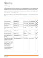
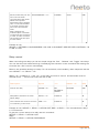
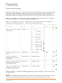
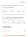
The onboard RS-232 ports (T1, R1, T2, R2) can be used for one- or two-way communication. Both
of the RS-232/IR ports can be used as either as RS-232 or as IR emitter.
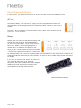
On the front of the Relay – 8 you will find 2 led for each RS232/IR port. When the Relay – 8 is
sending data on a RS232/IR port it’s green tx led will light. When the Relay – 8 is receiving RS232
data the orange rx led will light.
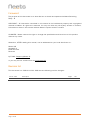
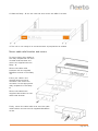
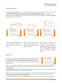
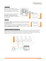
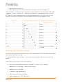
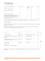
When used as RS-232 transmit
port: Connect the device to T1,
R1 and GND, as shown here
above.
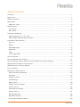
When used as single IR port:
Connect the IR emitter to T1
(white striped wire) and GND,
as shown above.
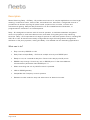
When used as dual IR port:
Connect the IR 1 emitter to
T1 (white striped wire) and
black wire on IR 1 emitter to
IR 2 emitter (white striped
wire), and black wire from IR 2
emitter to GND, as shown
above.
Digital I/O
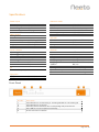
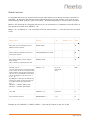
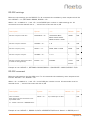
The Relay – 8 has 8 x I/O (Inputs/Outputs) available. They can be used
for an external control keypad, PIR (movement) sensor, keyboard
lock, extra relays, or other compatible uses. The ports are not
potential free; you may need external relays if you need to prevent
ground loops.
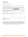
When used as outputs, the ports are active low. When indicated as active, the pins are tied to
GND through a FET transistor (also called open drain/collector function). Each can draw up to
24VDC/500mA.
For each output pin there is a led on the front of the Relay – 8. The led are on when the output pin
is activated (The output pin is connected to GND)
When used as inputs the voltage has to be below 1 Volt DC to be accepted as LOW, and above 4
VDC (but below 24 VDC) to be accepted as HIGH. The inputs are default HIGH and must be
connected to ground in order to change state.
For each input there is a led on the front of the Relay – 8. The led indicates the current state of
Page 8 of 23