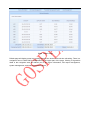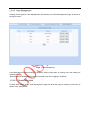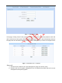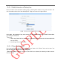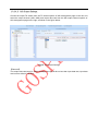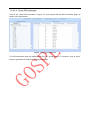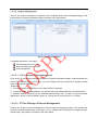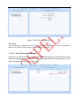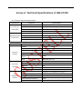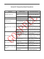
1
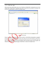
IP/ASI Adapter
GM-2730C
User Manual
GOSPELL Digital Technology Co., Ltd
GOSPELL Digital Technology Co., Ltd
Safety Instructions
Read this manual carefully before start operating the device.
Removal of device cover without permission may cause harm to human body and
the maintenance bond to be invalidated.
Handle the device with care to avoid crashing and falling, or otherwise it may cause
hazards to the internal hardware parts.
Keep all inflammable, metal and liquid materials from dropping into the device
casing, or otherwise it may cause damages to the device.
Avoid dusty places and places with heating resources nearby, direct projection of
sunlight or instant mechanical vibrations for installation of the device.
Connect the grounding connector on the rear panel to protective earth contact
properly while in operation.
Choose proper type of cable connectors for connecting network interfaces of the
device.
Avoid rapid and frequent power on/off, or it may cause damages to the
semiconductor chipsets.
Keep proper direction of the power cord when plug into or out from a power socket.
Do not touch the power socket with wet hands to avoid electric shocks.
Take off all jewelry or ornaments, such as ring, necklaces, watches, bracelets, etc.,
before operating the device, or otherwise the metal contact may possibly cause
short circuit and result in components damage.
Make sure the AC power is unplugged in case of operator services within the
device casing or close to power supply are needed.
Only GOSPELL trained and approved staff is permitted to perform live line
operation and maintenance within the device casing.
Ensure good ventilation when the device is in operation, or otherwise it may cause
damages to the device due to overheating.
It is recommended to unplug the power cord from the socket if the device will not
be used for a long period of time.
GOSPELL Digital Technology Co., Ltd
Table of Contents
Safety Instructions...........................................................................................................................2
Table of Contents ............................................................................................................................3
§1 Introduction ................................................................................................................................4
§1.1 Functionality ........................................................................................................................4
§1.2 Main Features .....................................................................................................................4
§1.3 Front Panel ..........................................................................................................................5
§1.4 Rear Panel...........................................................................................................................5
§1.5 Typical Application Architecture...........................................................................................7
§2 Before Use the Device ...............................................................................................................8
§2.1 Operation Requirements .....................................................................................................8
§2.1.1 Requirements for Digital TV Devices ...........................................................................8
§2.1.2 Requirements for Network Devices ..............................................................................8
§2.2 System Requirements .........................................................................................................8
§3 Operating the Device .................................................................................................................9
§3.1 Quick Start ...........................................................................................................................9
§3.2 Web Management Operation of GM-2730C .......................................................................9
§3.2.1 Web User Login ..........................................................................................................10
§3.2.2 User Management ......................................................................................................12
§3.2.3 Check Device Information ..........................................................................................15
§3.2.4 ASI Output Management ............................................................................................17
§3.2.5 System Management ..................................................................................................20
§3.3 Front Panel Operation of GM-2730C ................................................................................23
Annex A: Technical Specifications of GM-2730C .........................................................................24
Annex B: Frequently Asked Questions .........................................................................................25
Postscript.......................................................................................................................................26
§1 Introduction
§1.1 Functionality
GM-2730C is an IP/ASI adapter, which could transform the UDP packets derived from Gigabit
Ethernet input to TS stream, as well as send the recognized UDP port No. and its bit rate information
to CPU simultaneously, and then send TS to the output port according to the corresponding relation
between customized UDP input port and ASI output port, for completing the IP/ASI stream
transformation.
§1.2 Main Features
This product has the following key features:
IP output data rate range: 1~800Mbps
8 ASI output, bit rate range of each ASI valid data output. 1Mbps~160Mbps
Detect up to 250 UDP ports and real-time bit rate of each port.
Support IGMP2.0Internet Group Management Protocol
Each ASI output corresponds to one UDP port No.
Support user to view certain TS contains PID No. and its bit rate thereof.
Support Web-based network management.
Multi-lingual management user interface and documentation to suit both regional and
overseas markets.
Using the standard IU chassis. Appearance structure is consistent with GM-2730B.
Error alert display.
LCD display on front panel.
Power failure memory recovery.
Support online update for program.
Support configuration import/export.
Please refer to Annex A for detailed technical specifications.
4
§1.3 Front Panel
As shown in figure 1, there are one LCD display、one 6-key keypad and three LED indicators on the
front panel of GM-2730C.
The model type and logo notification information will be displayed on the LCD screen during the
device initialization stage. User can check part of the working status of device, and set part of the
parameters of GM-2730C by exploring a menu realized by buttons/LCD screen after system
initialization, see section §3.3 for details.
Fig.1 Front Panel View of GM-2730C
§1.4 Rear Panel
As shown in figure 2, the rear panel of GM-2730C consists of one power supply connector, one power
switch, one RJ45 connector for management, eight BNC ASI connectors for data input, one RJ45
connector for data output, and a grounding point.
Power Input Port: To connect to 100~240V 50/60Hz AC input;
Power Switch: To turn GM-2730C on or off;
Management Port: RJ45 interface, to connect to management server via 100BaseT or Gigabit
Ethernet;
ASI Input Port: BNC connector, to connect to data source devices of GM-2730C;
Data Output Port: RJ45 interface, to connect to data destination equipments of GM-2730C;
Grounding Point: To connect the device with conductive earth. Please make sure of proper
grounding of the device before start operating it for the safety of the operators and the device
itself!
11
12
13
14
15
16
Fig.2 Rear Panel View of GM-2730C
5
17
18
19
20
21
22
Diagram instructions:
No.
Functions
1
Fault Alarm Indicate
2
Status Indicator
3
Power Indicator
4
Display Screen
Left/Right Shift Keys: loop small menu/ move
5、8
cursor
Up/Down Shift Keys:
6、7
Cursor setting/parameter modification
9
ENTER: Store the modified results and carry out
function selection, able to loop in the main menu
MENU: Main menu cycling, parameter
10
modification and abandoning
11
Power Switch
12
Cable connector
13
Management Network Interface
14
Data Gigabit Network Interface
15-22
ASI Output Interface
§1.5 Typical Application Architecture
EPG Server
AD System
ASI/IP Adapter
DCM
Gigabit Switch
IP/ASI
Adapter
Management
Workstation
IPQAM
Modulator
HFC
Network
Fig.3 System Application Block Diagram of GM-2730C
Please refer to section §2.1.1 for details of supported transport stream formats.
The following devices may be able to provide input signal to GM-2730C (Only GOSPELL® products
listed):
1. GC-18xx Encoder series: DTV Encoders with IP output. These devices encode analogue or
uncompressed audio/video signals into UDP packets and output it to GM-2730C via IP port.
2. GM-8000 DTV stream processing platform: it scrambles and multiplexes the input TS
streams with IP formats, and then sends input TS streams to GM-2730C via IP port.
3. EPG system of IP edition (GS-9303): this system sends the EPG information to GM-2730C
via IP channel.
4. Advertising system (GS-9350): this system sends the advertising information to GM-2730C
via IP channel.
5. Adapter with IP output (GM-2730B): these devices transform the input ASI signals to IP
signals, and then send it to GM-2730C via IP port.
The following devices may be able to receive the output signal of GM-2730C (Only GOSPELL®
products listed):
1. GA-26xx series scrambler, GM-27xx series multiplexer: it scrambles and multiplexes the TS
streams received from GM-2730C via its ASI data input port, and send them to modulator via
ASI interface.
2. Modulator with ASI output (GQ-3650E): this device could make modulation of ASI format TS
stream received from GM-2730C.
[Remark] We strongly recommend use of GOSPELL products as GM-2730C’s input and output
signal processing devices, as the reliability of their unified performance is proven. For products of
other manufacturers, they may also be used together with GM-2730C, as long as they satisfy TS
signal characteristics stated in section §2.1 , but the compatibility between them may need further
verification in the real system applications.
§2 Before Use the Device
§2.1 Operation Requirements
In order to ensure proper operation of GM-2730C, there are some requirements for other digital TV
and network devices, which will connect with GM-2730C. Please see below for details:
§2.1.1 Requirements for Digital TV Devices
The output or input transport streams of the devices, which will provide signal source to or receive
signal from GM-2730C should comply with the following standards:
Transport Stream (TS): This means that the TS stream with one or more channels of digital TV,
digital audio broadcasting or any other digital TV services should comply with DVB standard; it must
contain PAT and PMT tables, which can completely describe the services.
For input IP interface, the TS packets must be encapsulated into UDP datagram. Each input TS
should have unique destination IP address (unicast or multicast) and port number. The length of the
UDP payload must be 7*188Byte (TS packets), and the payload must be synchronized by sync byte
0x47.
GM-2730C may be able to receive/feed multiple transport streams from/into any devices with the TS
format complies with the above-mentioned format.
§2.1.2 Requirements for Network Devices
The switch used for the GM-2730C data input and its source devices (the stream processing platform
shown in figure 3) must be a Layer 3 gigabit switch, indispensability to support IGMP2.0. The
backboard exchange speed must be higher than 10Gbps; the maximum data exchange speed of
each port must be higher than 1Gbps.
The switch for the GM-2730C and the managing workstation should be a 100M or gigabit switch, the
maximum data exchange speed of each port must be higher than 40Mbps.
§2.2 System Requirements
Management workstation must contain network device and support TCP/IP protocol. Microsoft
Windows 2000/XP or higher versions are the recommended operating systems of the management
workstation.
§3 Operating the Device
§3.1 Quick Start
Please follow the procedures below if it is the first time for you to use GM-2730C for constructing DTV
head-end system:
1、 Construct your hardware environment, including chassis installation, power supply system
deployment, and connecting switches, GM-2730C, the source device(s)(e.g. encoders,
stream processing platform, EPG sender, Ad inserter, etc.), the destination device(s)(e.g.
multiplexer, scrambler, modulator), management workstation (refer to Fig. 3)
2、 Plan for the IP addresses of management port and data input port, the ASI output interface of
GM-2730C; as well as number of digital TV transport streams, symbol rates, and modulation
modes. It is strongly recommended to take note of device addresses, port numbers and other
configurations and keep them safely for checking purposes in future
3、 Boot up each source devices of GM-2730C and configure the operating parameters, in order
to ensure the proper signal receiving or output of encoded digital TV transport streams.
Please refer to the user manuals of source devices provided by their suppliers for detailed
configuration
4、 Boot up GM-2730C, perform a factory reset through the front panel control (refer to section
§3.3 ). If you have known the management port IP address of the GM-2730C you are
currently using, and when it is in the same subnet with the management workstation, you may
also start configuring GM-2730C from the management workstation directly. Otherwise you
will need to configure the IP address of management port using front panel control (refer to
section §3.3 )
5、 Search for input programs tree, configure the output program settings of GM-2730C (refer to
section 错误!未找到引用源。)
6、 Configure the destination devices of GM-2730C, to adjust the network settings and
modulation settings of IPQAM.
7、 Make use of stream analyzer or set-top box to test the system. If the device works properly
and the output signal can be received, then it is ready for transmission in the real network
§3.2 Web Management Operation of GM-2730C
The management and control of GM-2730C can be done via a web browser. We recommend you to
use Internet Explorer 7.0 or higher version, and configure the display resolution to be (or higher than)
1024*768.
The default display language of the web UI of GM-2730C is “English”. To change the display
language into Chinese, you can select “Simplified Chinese” in the language dropdown menu in the
homepage and click “go” button after login. Unrecognizable codes may appear on your screen if there
is no Chinese font installed in your computer.
§3.2.1 Web User Login
After launching the Web browser, key in the IP address of GM-2730C’s management port into the
Address bar of Web browser. Embedded Web server of GM-2730C will prompt with username and
password for authentication, as shown in the figure below:
Fig.4 Web Login
There is only one default administrator account “admin” in GM-2730C with password of “gospell”.
Please use this account and password to login to the system for the first time operation of GM-2730C.
However, we strongly recommend you to change the password for this account immediately after first
login, and the new password should be kept safely. After successfully logging into the system, the
Web browser will display the default page of GM-2730C, as shown in the figure below:
Fig.5 Default Page
Default page will display some key working status of the device with real time refreshing. There is a
navigation area of GM-2730C’s configuration at the upper part of the page. Clicking of hyperlinks
listed in the navigation area will redirect you to the device information, ASI output management,
system management, and user management pages.
§3.2.2 User Management
Clicking of the hyperlink “User Management” will redirect you to User Management page, as shown in
the figure below:
Fig.6 User Management
User Management allows creating of new user, editing information of existing user, and deleting of
existing user.
【Remark】User Management page is accessible only when logging in as Admin.
§3.2.2.1 Create New Users
Clicking “Add” button in the “User Management” page will enter the page of creating a new user, as
shown in the figure below:
Fig.7 Create a New User
In this page, clicking “submit” after properly key in the new username and new password, which will
add a new account to the system. After successfully adding a new user, it will automatically redirect to
the page with user information table (homepage of User Management), as shown in the figure below:
Fig.8 Create New User - Complete
【Remark】
1、 All the accounts created in the “User Management” page are common users;
2、Common user can do system configuration, but is not allowed to perform task such as user
management and system upgrade.
§3.2.2.2 Modify Information of Existing User
User could enter user information editing page by clicking “Edit” button of any user account in the
user information table of the “User Management” page, as shown in the figure below:
Fig.9 Modify Information of Existing User
In this page, the password of any user account can be modified. Please click “Submit” button when
you finish the modification.
【Remark】
1、 When using GM-2730C for the first time, password of Admin account should be modified first
and kept safely.
2、 Account type cannot be modified.
§3.2.2.3 Delete Existing Users
In the user information table of the “User Management” page, click “Delete” button on the row of any
user will delete this user account from the system.
【Remark】Deleting of “Admin” account in GM-2730C is not allowed, but deleting of other common
users is allowed.
§3.2.3 Check Device Information
The default page of GM-2730C is the device information page.
When other pages are activated, user may click the hyperlink “Device Information” in the page
navigation area to turn back to the system working status page. As shown in the figure below:
Fig.10 Device Information
This page consists of three parts: current output status, data port address, and management port
address.
§3.2.3.1 Check Output Channel Status
The page will periodically read the current output status from the system, information including:
Output TS network information: source ID and UDP port No..
Input TS data rate
Output TS data rate
§3.2.3.2 Check Device Data Port Address
The data port address of GM-2730C, were showed at the bottom part of default device information
page, only refreshed one time at the moment of connection.
Fig.11 Device Data Port Address
【Remark】
The device management port address consists of two parts: IP, and subnet mask.
§3.2.3.3 Check Device Management Port Address
The management port address of GM-2730C, were showed at the bottom part of default device
information page, only refreshed one time at the moment of connection.
Fig.12 Device Management Port Address
【Remark】
The device management port address consists of three parts: IP, subnet mask, and gateway.
§3.2.4 ASI Output Management
User may enter the ASI output management page by clicking hyperlink “ASI Output Mangement” in
the navigation area, as shown in the figure below.
Fig.13 ASI Output Management
§3.2.4.1 Input Program Search
User may search the input TS information from data IP port by clicking “Refresh” in the ASI output
management page..
【Remark】
You must wait for the completion of the search process. The operation may take a few seconds,
depending on the number of input TS and the actual programs contained in each input TS. If there is
no input data in a certain input TS, it will take a little longer, because the process must wait for the
request to be timeout. In normal condition, the search process will be less than 12 seconds.
The page will be refreshed when the search process is completed. Then you can click and key in a
certain TS node in TS tree, and check the source IP, UDP port No., and input data rate of this TS.
§3.2.4.2 ASI Output Settings
Choose the output TS stream from the TS stream options of ASI management page on the left, and
select the output channel (ASI1-ASI8) and output data rate from the ASI output channel options of
ASI management page on the right, as shown in the figure below.
Fig.14 ASI Output Settings
【Remark】
The output data rate range is 1Mbps-160Mbps and should be no less than input data rate; input data
rate is set to default if not filled.
§3.2.4.3 Check PID Information
Click on the “check PID information” in figure 14, it will prompt with the PID information page, as
shown in the figure below.
Fig.15 Check PID Information
The PID information page will display all the PID No. and bit rates in TS streams, click on “back”
button to get back to the ASI output management page.
§3.2.5 System Management
Click on the “system management” hyperlink in the navigation area of web management page, it will
prompt with the system management page, as shown in the figure below.
Fig.16 System Management
3 available operations in this page:
Data management for IP port
Device management for IP port
User management
§3.2.5.1 IP Port Settings of Data Management
Click on the “IP port of data management” button of system management page, it will prompt with the
data IP port settings page. In this page, you can configure the input data port IP address, subnet
mask, and multicast address.
【Remark】
1、 The configuration of IP address must comply with IPv4 standard
2、IP address range: 001.000.000.001~126.255.255.254 and 128.000.000.001~223.255.255.254;
3、Multicast address can be set up to 8, multicast address range: 224.x.x.x-239.x.x.x.(some multicast
addresses in 244.0.x.x are permanent group, so it is best not to use this section, x is 0-255.)
§3.2.5.2 IP Port Settings of Device Management
Click on the “IP port of device management” button of system management page, it will prompt with
the device IP port settings page. In this page, you can configure the IP address of management port,
subnet mask, and gateway, as shown in the figure below.
Fig.17 IP Port of Device Management
【Remark】
The configuration of network port must comply with IPV4 standard, key in the re-configured IP
address in the browser address bar to access to the device properly.
§3.2.5.3 User Parameter Settings
Click on the “user parameter settings” button of system management page, it will prompt with the user
parameter settings page. In this page, you can configure the IP address of management port, subnet
mask, and gateway, as shown in the figure below.
Fig.18 User Parameter Settings
Export parameter settings: Click “Export Parameter” button, and configure the export parameter, save
the file in form of “GM2730C_backPara.tar” after choosing the save path, for importing the parameter
next time;
Import parameter settings: Click “Browse” button to choose the file path to import, and import the file
of “GM2730C_backPara.tar”, the settings of import parameter take effect upon clicking of “Import”
button.
【Remark】
1、 Import/export functions of parameter to easily save and configure the device parameters. We
strongly recommend you to export the configuration settings and keep a safe copy of the
backup file each time after modification of parameters.
2、 Under the Windows 7 system, set the “local path available when upload the file to server” in
“Custom Level” of Internet explorer to the status of “Start”, to import the device parameters
properly.
§3.3 Front Panel Operation of GM-2730C
Front panel LCD display of GM-2730C will show some initializing messages of the device at boot up
stage, such as but not limited to company logo, model number, etc. If there is an error during boot up,
then it will display the error message.
The front panel display will be locked if there is no key pressed within 60 seconds after device booting.
System configuration and menu browsing cannot be performed through the front panel keypad while
it is in LOCK status, and the LCD display will show current working status and alert messages (if
available) alternately.
User may unlock the LCD display by pressing “UP” and “DOWN” key continuously while it is locked,
in order to activate the front panel menu. After activating the menu, the LCD display will show the first
sub-menu of the main menu (VIEW ALARMS), as shown in the figure below:
Fig.19 Front Panel Menu
When entering operating menu, user may switch between different sub-menus by pressing “LEFT”
and “RIGHT” keys.
The front panel sub-menu items of GM-2730C are shown in the below table:
Menu ID
Function
1.0
Warning
messages
1.1
Management port
setting
1.2
Device serial No.
Operating Description
Remarks
Press “↑”“↓” button to switch between different
warning messages
Press “←”“→” button to switch between different digits
Press “↑”“↓” button to change the value of current digit
Press “ENTER” to submit operation
Read only
The IP address must be
located in the same subnet
with the manage PC
Read only
1.3
Version Info
Press “↑”“↓” button to switch between different
following items:
Main control software version;
Main control hardware version;
FPGA firmware version
FPGA hardware version
1.4
Factory reset
Press “Enter” button to execute a factory reset
The input/output programs
tree will be cleared
1.5
Language setting
Press“↑”“↓”button to switch between Chinese and
English, Press “Enter” to confirm
Operating language
Read only
After complete menu operation, user may lock the front panel LCD display and keypad by
pressing ”MENU” and “ENTER” key continuously.
Annex A: Technical Specifications of GM-2730C
A.1 Common Technical Specifications
Characteristic
Properties
Specifications
AC Input Voltage
100~240VAC
Power Supply &
AC Input Frequency
50~60Hz
Consumption
Power Consumption
7W
No. of Power Supply Modules
2
Operating Temperature
0℃~45℃
Storage Temperature
-20~55℃
Air Pressure
86~106KPa
Humidity
10%~90%
Operating/Storage
Environment
A.2 Interfaces
Characteristic
Data input
interface
Properties
Specifications
Standard
IEEE 802.3 1000BASE-T
Physical interface type
RJ45
Interface number
1
Physical bandwidth
1250Mbps
Signal
transmission
maximum
distance
Data output
interface
Web
management
interface
100M
Cable
Superoxide five or six
ASI interface number
8
Physical interface type
BNC
Resistance
75Ω
Electrical level
800mv±5%
Physical bandwidth
270 Mbps
Standard
IEEE 802.3 100/1000BASET self-adaptor
Physical interface type
RJ45
Physical bandwidth
1250Mbps
Signal transmission distance
100M
Cable
Superoxide five or six
Annex B: Frequently Asked Questions
Symptoms
Possible Causes
Recommended Solutions
Improper power supply
“POWER” indicator unlit
“STATUS” light on (red)
Improper connection of power
cable
Plug in the power supply cable
Didn’t turn on the switch
Turn on the power switch
No input signal
Refer to WEB page as shown of
“No Signal Input”
No input signal
Reboot the device, if the problem
persists, please replace the
device
“ALARM” glimmer
Device malfunction
Improper connection of Data IP Check if the network interface
network port
connect properly
WEB page shows “No Signal
Input”
Set the data IP port parameters
properly, ensure it has the same
segment with program source IP
IP conflict or mismatch
No signal input in data IP
network port
Fail to open the WEB page
Improper connection of network
management interface
Check if the network interface
connect properly
Mis-configuration
parameters
Reset the network parameters in
front panel, ensure it has the
same segment with host
of
network
Abnormal browser
Repair network connection and
restart the browser
No signal input
Please refer to WEB page shows
“No Signal Input”
Improper connection of output
interface
Check if the output interface is
connect properly
Input of mosaic program
Check the IP input source
With no signal output in ASI
With mosaic in ASI output
program
ASI output bit rate lower than IP Reset the ASI output bit rate with
input bit rate
no less than input bit rate
Postscript
Thank you for purchasing products of GOSPELL Digital Technology Co., Ltd!
GOSPELL Digital Technology Co., Ltd and Chengdu TONCY Digital System Co., Ltd fully
own the intelligent property rights of this product. Our company reserves the rights to
pursue legal actions against unauthorized duplication and usage of the product and its
software by any organizations or individuals.
For ensuring long-term stability of product operation, please strictly follow the methods,
procedures and constraints introduced by this manual while operating the device.
After purchasing of our devices, please leave your contact details to our customer service
staff. We will track the usage of the device randomly, and inform you while there is a new
version of software available for your device upgrading.
When encountering malfunction of the device, please contact our customer service staff in
time for maintenance and repairing.
GOSPELL Digital Technology Co., Ltd
Address: F10-F12 Idea Land, F518 Baoyuan Road, Baoan Central Distinct, Shenzhen,
China
Technical Support Tel: +86-755-26715680
Fax: +86-755-26716142
Technical Support Email: [email protected]
Website: www.gospell.com
26