1
Dual Feed DC Telecom
Power Supply
Installation and User’s Guide
9380 Carroll Park Drive
San Diego, CA 92121-2256
858-882-8800
www.ccpu.com
Continuous Computing Corp.
San Diego, CA
Page 1
Dual Feed DC Telecom Power Supply User’s Guide
File: CC00313-00
Last saved: 2/12/01 4:57 PM
©2000-2001 Continuous Computing Corporation. All rights reserved.
The information contained in this document is provided “as is” without any express representations of warranties. In addition,
Continuous Computing Corporation disclaims all implied representations and warranties, including any warranty of merchantability,
fitness for a particular purpose, or non-infringement of third party intellectual property rights.
This document contains proprietary information of Continuous Computing Corporation or under license from third parties. No part of
this document may be reproduced in any form or by any means or transferred to any third party without the prior written consent of
Continuous Computing Corporation.
Continuous Computing, the Continuous Computing Corporation logo, Continuous Control Node (CCN), Continuous System Controller,
CCPUnet, CCNtalk, Field Replaceable Microprocessor (FRµ), and Field Replaceable System are trademarks or registered trademarks of
Continuous Computing Corporation in the United States and other countries.
Sun, the Sun logo, SPARCengine, Solaris, and OpenBoot are trademarks or registered trademarks of Sun Microsystems Inc. in the
United States and other countries. All SPARC trademarks are used under license and are trademarks or registered trademarks of SPARC
International, Inc. in the United States and other countries. Products bearing SPARC trademarks are based upon an architecture
developed by Sun Microsystems, Inc.
CompactPCI is a registered trademark of PICMG.
The information contained in this document is not designed or intended for use in human life support systems, on-line control of aircraft,
aircraft navigation or aircraft communications; or in the design, construction, operation or maintenance of any nuclear facility.
Continuous Computing Corporation disclaims any express or implied warranty of fitness for such uses.
Continuous Computing Corp.
San Diego, CA
Page 2
Dual Feed DC Telecom Power Supply User’s Guide
File: CC00313-00
Last saved: 2/12/01 4:57 PM
Table of Contents
1
INTRODUCTION ........................................................................................................... 5
DESCRIPTION ...........................................................................................................................................5
USING THIS GUIDE ..................................................................................................................................6
TYPOGRAPHIC CONVENTIONS .................................................................................................................6
DEFINITIONS OF TERMS ...........................................................................................................................7
POWER SUPPLY WIDTHS .........................................................................................................................7
SYSTEM BLOCK DIAGRAM ......................................................................................................................7
PHOTOS ...................................................................................................................................................8
2
UNPACKING, INSTALLING, AND STARTING UP ....................................................... 10
ELECTROSTATIC DISCHARGE (ESD)......................................................................................................10
STORAGE ...............................................................................................................................................10
UNPACKING ...........................................................................................................................................10
INSTALLING THE POWER SUPPLY ..........................................................................................................10
INSTALLING THE POWER INPUT MODULE ..............................................................................................11
3
GROUNDING YOUR SYSTEM ..................................................................................... 13
DEFINITIONS OF TERMS .........................................................................................................................13
SYSTEM GROUNDING OPTIONS..............................................................................................................13
Frame Ground to Digital Ground Connected .............................................................................13
Frame Ground to Digital Ground Isolated .................................................................................15
POWERING ON THE SYSTEM ..................................................................................................................17
Enabling system from CCN front panel.......................................................................................17
Enabling system from Craft console............................................................................................17
POWERING OFF THE SYSTEM .................................................................................................................18
Disable system from CCN front panel.........................................................................................18
Disable system from Craft console..............................................................................................18
4
TROUBLESHOOTING ................................................................................................. 19
TROUBLESHOOTING SCENARIOS ............................................................................................................19
CHECK THE LEDS .................................................................................................................................19
USE THE CCN .......................................................................................................................................19
Use the faults command .........................................................................................................19
Use the voltages command ....................................................................................................20
CHECK THE FUSES .................................................................................................................................20
REMOVING THE POWER SUPPLY ............................................................................................................21
REMOVING THE POWER INPUT MODULE ...............................................................................................21
CONTACT TECHNICAL SUPPORT ............................................................................................................21
5
LEDS, CONNECTOR USAGE, AND SPECIFICATIONS ................................................ 22
LEDS ....................................................................................................................................................22
The INPUT LED..........................................................................................................................22
The ON LED................................................................................................................................23
The FLT LED ..............................................................................................................................23
CONNECTOR USAGE ..............................................................................................................................23
J1000 Pinout ...............................................................................................................................23
SPECIFICATIONS ....................................................................................................................................24
6
TECHNICAL SUPPORT ............................................................................................... 26
CONTACTING TECHNICAL SUPPORT ......................................................................................................26
Continuous Computing Corp.
San Diego, CA
Page 3
Dual Feed DC Telecom Power Supply User’s Guide
File: CC00313-00
Last saved: 2/12/01 4:57 PM
TABLE OF FIGURES
FIGURE 1
FIGURE 2
FIGURE 3
FIGURE 4
FIGURE 5
FIGURE 6
FIGURE 7
FIGURE 8
FIGURE 9
SYSTEM BLOCK DIAGRAM .......................................................................................................7
100W DUAL FEED DC TELECOM POWER SUPPLY ..................................................................8
150W DUAL FEED DC TELECOM POWER SUPPLY ..................................................................9
350W DUAL FEED DC TELECOM POWER SUPPLY ..................................................................9
CARD INSTALLATION AND REMOVAL ....................................................................................11
CONNECTING THE POWER INPUT MODULE CONNECTOR TO MIDPLANE .................................12
CCN FRONT PANEL...............................................................................................................17
LEDS FOR 100W, 150W, AND 350W POWER SUPPLIES .......................................................22
J1000 PINOUT VIEWED FROM BOARD EDGE ...........................................................................23
TABLE OF TABLES
TABLE 1
TABLE 2
TABLE 3
TABLE 4
TABLE 5
TABLE 6
TABLE 7
TABLE 8
TYPOGRAPHIC CONVENTIONS ..................................................................................................6
POWER SUPPLY SLOT WIDTHS ..................................................................................................7
FRAME GROUND TO DIGITAL GROUND CONNECTED WITH BARRIER STRIP POWER ENTRY .....13
FRAME GROUND TO DIGITAL GROUND CONNECTED WITH POWER ENTRY CONNECTORS .......14
FRAME GROUND TO DIGITAL GROUND ISOLATED WITH BARRIER STRIP POWER ENTRY .........15
FRAME GROUND TO DIGITAL GROUND ISOLATED WITH BARRIER STRIP ENTRY .....................16
VOLTAGES COMMAND OUTPUTS .............................................................................................20
SPECIFICATIONS .....................................................................................................................25
Continuous Computing Corp.
San Diego, CA
Page 4
Dual Feed DC Telecom Power Supply User’s Guide
File: CC00313-00
Last saved: 2/12/01 4:57 PM
1 Introduction
Welcome to the Dual Feed DC Telecom Power Supply User’s Guide. This guide contains information
about the installation and use of Continuous Computing Corporation’s 100W, 150W, and 350W Dual
Feed DC Telecom Power Supplies.
This guide includes the following information related to the 100W, 150W, and 350W Dual Feed DC
Telecom Power Supplies:
•
Unpacking, installing, and starting up
•
Grounding your system
•
Troubleshooting
•
Connector usage and specifications
Description
The Continuous Computing Telecom Power Supply offers 100, 150, or 350 watts of Hot Swappable,
load-sharing power for a CompactPCI system. The Power Supply is designed for the Central Office,
with dual input feeds and –48V DC input. Typical systems combine two Supplies to provide redundant
power. Each Power Supply also provides a standby power output for use by a Continuous Control Node
(CCN).
Features of the Dual Feed DC Telecom Power Supply include:
•
•
•
•
•
•
Hot Swap and Load Sharing
The Power Supply is designed for redundant operation. A failed Power Supply can be
replaced without application downtime. Load sharing ensures that supplies run cooler,
leading to increased system reliability.
Standby Power
Standby power provides an output that is always on to power a Continuous Control Node.
This enables remote power cycling and system diagnostics even when the Power Supply is
off.
Over Temperature and Short Circuit Protection
Protection features reduce the possibility of hardware damage during extreme temperatures
or fault conditions.
Remote Sense on +5 and +3.3V
Remote sense provides high-quality power to critical system components.
Dual Input Feeds
Dual power feeds allow the system to continue running even if one feed drops out.
6U CompactPCI Form-Factor
Standard 6U form-factor allows for easy integration into CompactPCI system without
awkward divider rails.
The Telecom Power Supply is a Basic Hot Swap device. PICMG 2.1 R1.0 describes Basic Hot Swap as
a board powered and enabled for access by the PCI bus in configuration space only upon insertion. The
board’s configuration space is not yet initialized. You must initiate software connection at the system
console. The power circuitry is controlled so that inserting in or extracting from a live redundant system
will not cause any electrical damage. If the system is not redundant, it must be halted before servicing.
Continuous Computing Corp.
San Diego, CA
Page 5
Dual Feed DC Telecom Power Supply User’s Guide
File: CC00313-00
Last saved: 2/12/01 4:57 PM
Using This Guide
This guide is written for computer technicians and hardware and software engineers.
It is assumed that the user of the Power Supply is:
•
•
Familiar with the handling of ESD-sensitive electronic equipment.
Standard -48V wiring techniques and safety precautions.
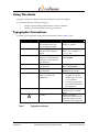
Typographic Conventions
A summary of the typographic conventions used in this guide is listed in Table 1 below.
Typeface/Symbol
AaBbCc123
AaBbCc123
<AaBbCc123>
[AaBbCc123]
{<a> <b>}
AaBbCc123
ABC
!
Table 1
Continuous Computing Corp.
San Diego, CA
Meaning
Example
The names of commands,
files and directories; onscreen computer output
What you type, contrasted
with on-screen computer
output
Command-line placeholder or
token to be replaced with a
real name or value (do not
type brackets)
Optional argument (do not
type brackets)
Required argument (do not
type brackets)
Book titles, new words or
terms, or words to be
emphasized
Edit your .login file.
At the ok prompt….
Acronyms
Caution
To turn the unit on, type on
at the ccpu> prompt. i.e.,
ccpu>:on
To delete a file, type rm
<filename>.
[help]
dir [<filename>]
{<na> <cmd>}
grade {a, b, c, d, f}
• This manual is used in
conjunction with the
SPARCengine CP1500
User’s Manual.
• You must be grounded
to avoid ESD damage to
the equipment.
Locate the On / Off toggle
switch on the CCN front
panel.
Failure to heed the
instructions that follow the
Caution symbol may result
in damage to the equipment.
Typographic conventions
Page 6
Dual Feed DC Telecom Power Supply User’s Guide
File: CC00313-00
Last saved: 2/12/01 4:57 PM
Definitions of Terms
Power Supply
Refers to the larger card installed in the front of the
system. Power Supply also refers to the larger card and
Power Input Module as a unit.
Refers to the interface module installed at the back of the
system.
Refers to the module that monitors and controls a
compute node in a CompactPCI system.
Power Input Module
Continuous Control Node (CCN)
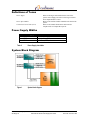
Power Supply Widths
Power Supply
100W
150W
350W
Table 2
Width
1 slot (4HP)
1 ½ slots (6HP)
2 slots (8HP)
Power Supply slot widths
System Block Diagram
Figure 1
Continuous Computing Corp.
San Diego, CA
System block diagram
Page 7
Dual Feed DC Telecom Power Supply User’s Guide
File: CC00313-00
Last saved: 2/12/01 4:57 PM
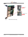
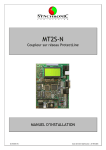
Photos
Feed A & B fuses
Alarm/Standby (STBY)
power fuse
Figure 2
Continuous Computing Corp.
San Diego, CA
100W Dual Feed DC Telecom Power Supply
Page 8
Dual Feed DC Telecom Power Supply User’s Guide
File: CC00313-00
Last saved: 2/12/01 4:57 PM
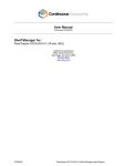
Feed A & B fuses
Alarm/Standby
(STBY) power fuse
Figure 3
150W Dual Feed DC Telecom Power Supply
Feed A & B fuses
Alarm/Standby
(STBY) power fuse
Figure 4
Continuous Computing Corp.
San Diego, CA
350W Dual Feed DC Telecom Power Supply
Page 9
Dual Feed DC Telecom Power Supply User’s Guide
File: CC00313-00
Last saved: 2/12/01 4:57 PM
2 Unpacking, Installing, and Starting Up
Electrostatic Discharge (ESD)
!
Caution – The Power Supply contains electronic components that
are extremely sensitive to static electricity. Ordinary amounts of
static from clothing and the surrounding environment may destroy
components.
What to do
•
•
Use an antistatic mat.
Use an antistatic wrist or foot strap.
Storage
•
If the Power Supply is to be stored before unpacking, see Table 8 for environmental storage
specifications.
Unpacking
!
Caution – Always maintain an ESD-safe environment when handling
the Power Supply. It contains many components that can be
destroyed by ESD.
•
•
Inspect the shipping container for any in-transit damage and report it to shipping agent if
necessary.
Carefully unpack the Power Supply from its shipping container.
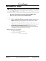
Installing the Power Supply
!
Caution – You may only install the Power Supply in a slot
specifically provided for it by Continuous Computing. The Power
Supply is not interchangeable with supplies from other
manufacturers, even if they use the same connector.
Continuous Computing Corp.
San Diego, CA
Page 10
Dual Feed DC Telecom Power Supply User’s Guide
File: CC00313-00
Last saved: 2/12/01 4:57 PM
1.
2.
3.
Slide the card into its slot in the system chassis. As the card’s ejector latches engage the chassis,
apply forward pressure while pushing the ejector latch handles toward each other. See Figure 5
for an illustration of Power Supply installation.
When properly installed, the connectors of each card will be fully engaged with the chassis’
midplane. The Power Supply’s front panel will sit flush with the front panels of the other cards.
Install and tighten the captive screw (supplied with the Power Supply) of each ejector latch
handle to secure the card to the system chassis.
Captive Screw
Latch Handle Cam
Alignment Pin
Ejector Latch
Handle
Closed
Open
Card
Card
Connector
Open
Front
Figure 5
Side
Closed
Card installation and removal
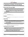
Installing the Power Input Module
1.
Connect the Power Input Module’s 6-pin connector to the midplane.
Note: There are two available midplane options. Each has a 6-pin connector. See Figure 6 for
location details.
Continuous Computing Corp.
San Diego, CA
Page 11
Dual Feed DC Telecom Power Supply User’s Guide
File: CC00313-00
Last saved: 2/12/01 4:57 PM
Two
available
midplane
options
Figure 6
2.
3.
Connecting the Power Input Module connector to midplane
Press the Power Input Module faceplate in between the adjacent faceplates and tighten the
Module’s four captive screws using a #1 Phillips screwdriver.
Connect 48V according to the instructions listed in Section 3, “Grounding Your System.”
Continuous Computing Corp.
San Diego, CA
Page 12
Dual Feed DC Telecom Power Supply User’s Guide
File: CC00313-00
Last saved: 2/12/01 4:57 PM
3 Grounding Your System
Definitions of Terms
Earth Ground
Connects to earth to protect from damage due to lightening or static
electricity; also establishes a zero voltage reference.
Frame Ground
Grounds the system chassis usually via an external ground pin located on
the rear of the rack. Normally connected to Earth Ground.
Digital Ground
The internal circuitry ground used in processor and peripheral cards and
other system electronics. This ground may be directly connected to Frame
Ground or left isolated depending on your preference.
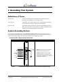
System Grounding Options
Your system can be grounded in two ways: connected or isolated. Identify the type of power entry your
system has and the grounding option you desire in the diagrams below. Once you have identified your power
entry and chosen a grounding option, follow the instructions for grounding your system.
Frame Ground to Digital Ground Connected
FGND
-48 A
-48V (red)
-48 B
-48 B
Return (black)
RTN B
RTN B
Return (black)
Feed B
Table 3
Continuous Computing Corp.
San Diego, CA
DGND
FGND
-48V (red)
Feed A
shorting bar
(optional)
RTN A
Frame Ground (green)
RTN A
1
-48 A
Digital Ground (black)
DGND
Barrier strip power entry
earth ground
2
1.
Required: Connect Frame Ground to
Earth Ground using ground wire.
2.
Additional option: Connect Digital
Ground to Frame Ground with metal
shorting bar (available from Continuous
Computing Corporation).
Frame Ground to Digital Ground Connected with barrier strip power entry
Page 13
Dual Feed DC Telecom Power Supply User’s Guide
File: CC00313-00
Last saved: 2/12/01 4:57 PM
Power entry connectors
ground stud 2
DGND
PIN 1: -48V (red)
1 PIN 2:
shorting plug
3
(optional)
FGND (green)
PIN 3: RTN (black)
FGND
FEED A
earth ground
FEED B
PIN 1: -48V (red)
1 PIN 2: FGND (green)
1.
PIN 3: RTN (black)
2.
FEED A
3.
PIN 1: -48V (red)
PIN 2: FGN (green) 1
PIN 3: RTN (black)
Required: Connect Frame Ground
to Earth Ground with ground wire.
or
Use ground stud to connect to Earth
Ground.
Additional option: Use shorting
plug (available from Continuous
Computing Corporation) to short
Digital Ground to Frame Ground.
DGND
shorting plug 3
(optional)
FGND
ground stud 2
earth ground
FEED B
PIN 1: -48V (red)
PIN 2: FGN (green) 1
PIN 3: RTN (black)
Table 4
Continuous Computing Corp.
San Diego, CA
Frame Ground to Digital Ground Connected with power entry connectors
Page 14
Dual Feed DC Telecom Power Supply User’s Guide
File: CC00313-00
Last saved: 2/12/01 4:57 PM
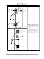
Frame Ground to Digital Ground Isolated
DGND
FGND
-48 A
-48 B
-48 B
Return (black)
RTN B
Feed B
Table 5
Continuous Computing Corp.
San Diego, CA
DGND
(optional)
RTN A
-48V (red)
RTN B
Return (black)
DGND
-48V (red)
Feed A
FGND
1 Frame Ground (green)
RTN A
Digital Ground (black)
-48 A
Barrier strip power entry
2
1.
Required: Connect Frame Ground to Earth
Ground using ground wire.
2.
Additional option: Connect Digital Ground
on barrier strip to Digital Ground to all
systems
earth ground
Frame Ground to Digital Ground Isolated with barrier strip power entry
Page 15
Dual Feed DC Telecom Power Supply User’s Guide
File: CC00313-00
Last saved: 2/12/01 4:57 PM
Power entry connectors
ground stud 2
DGND
PIN 1: -48V (red)
DGND 3
(optional)
1 PIN 2: FGND (green)
PIN 3: RTN (black)
FGND
FEED A
earth ground
FEED B
PIN 1: -48V (red)
1 PIN 2: FGND (green)
PIN 3: RTN (black)
1.
2.
FEED A
PIN 1: -48V (red)
PIN 2: FGN (green) 1
3.
Required: Use ground stud to connect
Frame Ground and Earth Ground.
or
Use ground stud to connect to Earth Ground.
Additional option: Use connector to connect
Digital Ground to all systems.
PIN 3: RTN (black)
DGND
DGND 3
(optional)
FGND
ground stud 2
earth ground
FEED B
PIN 1: -48V (red)
PIN 2: FGN (green) 1
PIN 3: RTN (black)
Table 6
Continuous Computing Corp.
San Diego, CA
Frame Ground to Digital Ground Isolated with barrier strip entry
Page 16
Dual Feed DC Telecom Power Supply User’s Guide
File: CC00313-00
Last saved: 2/12/01 4:57 PM
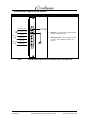
Powering On the System
To enable power to your system and, in turn, the Power Supply, you can use two different methods.
•
Enabling system from the Continuous Control Node (CCN) front panel
•
Enabling system from the Craft console
!
Caution – Ensure proper operating temperature ranges are met!
Permanent damage to the Power Supply may result from
overheating. See Table 8 for operating specifications.
APP
Application (user defined) LED
ON
On LED
On / Off Toggle Switch
Off LED
OFF
CONS
DB9 Serial Female DCE
Craft Console Connection
CR
MJ
MN
Critical Fault LED
Major Fault LED
Minor Fault LED
RST
Reset Switch (Recessed)
FLT
Controller Fault LED
SWP
Swap OK LED
Figure 7
CCN front panel
Enabling system from CCN front panel
1.
2.
Locate the On/Off toggle switch on the CCN front panel. See Figure 7 for location details.
Note: This switch utilizes a locking mechanism to avoid accidental actuation. Pull the switch lever
out and push up or down as needed.
Pull the On/Off toggle switch lever out and push up towards the ON LED and hold for one second.
This will turn the system on.
Enabling system from Craft console
At the 00 ccncli> prompt, type on
Continuous Computing Corp.
San Diego, CA
Page 17
Dual Feed DC Telecom Power Supply User’s Guide
File: CC00313-00
Last saved: 2/12/01 4:57 PM
Powering Off the System
!
Caution – Before removing power from your system, ensure that the
operating system has completely shut down. Failing to do so may
cause disk corruption.
1.
2.
Shut down the system’s operating system. In Solaris, do this using the halt command.
Disable power from your system using one of the methods listed below.
Disable system from CCN front panel
•
•
•
Locate the On/Off toggle switch on the CCN front panel. See Figure 7 for location details.
Note: This switch utilizes a locking mechanism to avoid accidental actuation. Pull the
switch lever out and push up or down as needed.
If CCN daemon is installed and configured for shutdown on the CCN: Pull the On/Off
toggle switch lever out and pushing down towards the OFF LED; hold for one second. The
OFF LED will begin to blink. Once the operating system has shut down, the ON LED will
go dark and the OFF LED will stop blinking and stay lit.
If CCN daemon is not installed on the CCN: Ensure that the operating system is
completely shutdown using the halt command. Pull the On/Off toggle switch lever out
and push down towards the OFF LED; hold for five seconds.
Disable system from Craft console
•
If CCN daemon is installed:
at the 00 ccncli> prompt, type off
•
If CCN daemon is not installed:
at the 00 ccncli> prompt, type forceoff
Continuous Computing Corp.
San Diego, CA
Page 18
Dual Feed DC Telecom Power Supply User’s Guide
File: CC00313-00
Last saved: 2/12/01 4:57 PM
4 Troubleshooting
Troubleshooting Scenarios
In the event that the Power Supply should fail in any way, use the following procedures to troubleshoot.
Note: The Power Input Module contains only passive components and therefore is extremely unlikely to
be the cause of failure.
Check the LEDs
If the INPUT LED is not on, one or more of the following applies:
•
The -48V source has not been enabled externally.
•
The Power Input Module is not correctly connected or the cables bringing power have
improper polarity.
•
Both the Feed A and Feed B fuses have blown on the Power Supply. Use the “Check the
Fuses” procedure below to determine if the fuses have blown.
If the FLT LED is on, one or more of the following applies:
•
One of the fuses, or both, have blown. Use the “Check the Fuses” procedure below to
determine if the fuses have blown.
•
Feed A or Feed B, or both, have lost power from the external source.
•
The onboard converters have failed.
Note: The FLT LED will light only if the CCN is connected.
Use the Command Line Interface (CLI) or the GUI to the CCN to further troubleshoot the Power
Supply and find out whether the problem is external or internal. See the section below, “Use the CCN,”
to troubleshoot from the CLI.
Use the CCN
If the above conditions have been checked and do not solve the problem, you can use the CCN to
investigate the status of the Power Supply. If the CCN is receiving alarm power from a redundant
Supply within that system, or from a crossover connection of alarm power from the opposite side of the
system—even if a Power Supply is dead—the CCN can still be used to determine problems with the
Power Supply.
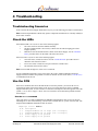
Use the faults command
First, login to the CCN and type faults. The faults command shows what is active at the time,
indicating one or more of the following: a Feed A fault, a Feed B fault, or a power converter fault. The
output from the faults command will look as follows:
samplesys ccncli> faults
# ST Description
1 L
Sampled ALM12A out
2 L
Sampled ALM12B out
8 A
Power Supply A not
9 A
Power Supply B not
Continuous Computing Corp.
San Diego, CA
of range (use 'voltages')
of range (use 'voltages')
present
present
Page 19
Dual Feed DC Telecom Power Supply User’s Guide
File: CC00313-00
Last saved: 2/12/01 4:57 PM
10 L
Disk A not present
16 L
Power Supply A 48V feed A
17 L
Power Supply A 48V feed B
20 L
Power Supply B 48V feed A
21 L
Power Supply B 48V feed B
27 A
Application heartbeat not
samplesys ccncli>
no power
no power
no power
no power
received within timeout period
Legend:
A=
Active
L =
Latched
M=
Masked
Note: If the condition causing the fault is current, then the fault is “active”. Once the condition has been
corrected, then the fault is “latched”. Faults can be cleared using the faults reset command.
If the power switch on the CCN is used to turn the Supply on or off and the Power Supply’s ON LED
does not come on when it should, a communication problem between the CCN and the Power Supply
has occurred. Therefore, either the CCN or the Power Supply will need to be replaced. To determine
which is defective, first try swapping in another Power Supply. If the new Supply does not work, try
swapping in another CCN. By doing so, you will be able to figure out if the communication problem is
due to the Supply or the CCN.
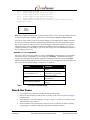
Use the voltages command
If the above does not solve the problem, try using the voltages command on the CCN to determine
whether the currents or temperature are out of range. The voltages command lists all sampled
voltages and temperatures along with the minimum and maximum values since the last voltages
reset command (which clears all of the stored min/max values). In addition, the allowable upper and
lower limits for each sampled voltage or temperature are displayed.
Output
TEMP0
ALM12A and ALM12B
TEMP1
(the remaining voltages)
Table 7
Indicates
The temperature within the
chassis.
The CCN power feeds
(ALM12B is only present in
multi-node systems).
An extra sensor that is typically
not connected.
The CompactPCI midplane
voltages.
voltages command outputs
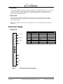
Check the Fuses
1.
2.
3.
4.
If your system uses a single Power Supply, halt the operating system.
Remove the Power Supply from the system. To do this, use the “Removing the Power Supply”
procedure below.
Using the photo of your Power Supply (see Figure 2, Figure 3, or Figure 4), locate the Feed A
and Feed B fuses on your board.
With a continuity meter check the fuse on the card. If one or both fuses are blown, return the
Power Supply to Continuous Computing Corporation for analysis and repair.
Continuous Computing Corp.
San Diego, CA
Page 20
Dual Feed DC Telecom Power Supply User’s Guide
File: CC00313-00
Last saved: 2/12/01 4:57 PM
Removing the Power Supply
To remove the Power Supply:
1.
2.
3.
4.
5.
If your system uses a single Power Supply, halt the operating system. If your system is
redundant, skip the next step.
Power down the system.
Loosen the captive screw on each ejector latch handle to disengage the Power Supply from the
system chassis. Refer to Figure 5 for ejector latch handle details.
Press the ejector latch handles away from the faceplate.
Gently slide the module out of the system chassis.
Removing the Power Input Module
To remove the Power Input Module:
1.
2.
3.
4.
5.
6.
7.
Halt the operating system.
Power down the system.
Disable the 48V at the source to prevent accidental contact with hazardous voltages.
Disconnect the connectors from the panel (ring lugs or 3-pin AMP MATE-N-LOK).
Unscrew the panel.
Disconnect the 6-pin, keyed Molex connector from the midplane.
Remove the Power Input Module.
Contact Technical Support
If you continue to experience problems with your Power Supply, contact the Technical Support team at
Continuous Computing. See Section 6 for contact information.
Continuous Computing Corp.
San Diego, CA
Page 21
Dual Feed DC Telecom Power Supply User’s Guide
File: CC00313-00
Last saved: 2/12/01 4:57 PM
5 LEDs, Connector Usage, and
Specifications
INPUT
Figure 8
Input OK LED (green)
ON
Output ON LED (green)
FLT
Fault LED (red)
LEDs for 100W, 150W, and 350W Power Supplies
LEDs
The INPUT LED
The green INPUT LED is activated when –48V are present on Feed A, B, or both. Whenever the
INPUT LED is lighted, the Supply is generating standby power for an attached CCN.
Note: A solder side cover is on the Power Supply. However, if you are ejecting the Power Supply before
removing it completely from the chassis, you should wait for the INPUT LED to go completely dark,
indicating that any hazardous voltages on the board have been discharged.
Continuous Computing Corp.
San Diego, CA
Page 22
Dual Feed DC Telecom Power Supply User’s Guide
File: CC00313-00
Last saved: 2/12/01 4:57 PM
The ON LED
The green ON LED is activated when the Power Supply has been enabled to supply 5V, 12V, 3.3V, and
–12V to the PCI portions of the system circuitry. Therefore, 48V power can be coming in, but the
converters may not be enabled such that they are generating output power from the 48V; this is the
distinction between INPUT and ON.
The FLT LED
The red FLT (fault) LED is activated when one or both of the fuses have blown. The FLT LED is
activated when Feed A, Feed B, or both, have lost power from the external source or, the onboard
converters have failed.
Note: The FLT LED is driven by the CCN. Therefore, if the CCN is not attached, the FLT LED will
never light.
Connector Usage
J1000 Pinout
-48V Feed A
-48V Return
-48V Feed B
FGND
Pin #
1
2
3
4
5
6
7
8
A
3V sense 3V sense +
RSVD
+12V stby
SDA
SCL
+12V
-12V
B
Fault LED (A)
Fault LED (K)
Feed A detect
Feed B detect
DGND
+12V
+12V
-12V
C
3V parallel
PWR enable
5V parallel
5V sense 5V sense +
+12V
+12V
-12V
C B A
1
2
3
4
5
6
7
8
DGND
+5V
DGND
+3.3V
Figure 9
Continuous Computing Corp.
San Diego, CA
J1000 pinout viewed from board edge
Page 23
Dual Feed DC Telecom Power Supply User’s Guide
File: CC00313-00
Last saved: 2/12/01 4:57 PM
Specifications
100W
150W
350W
+5V
12A
30A*
30A
+3.3V
15A
30A*
30A
+12V
6A
8.3A*
8.3A
-12V
0.5A
0.5A
0.5A
1A
1A
1A
Output Current
Standby 12V
* Note: Due to the use of a shared heatsink, the maximum combined power dissipation for
+5V, +3.3V, and +12V is 150W.
Output Voltage
5V
5.0V ± 3%
3.3V
3.3V ± 5%
12V
12.0V ± 5%
-12V
-12.0V ± 5%
Standby 12.3 ± 5%
Input Power
Voltage: -42VDC to -56VDC
12A maximum steady state
30A maximum inrush
Front Panel LEDs
Input Power Available
On
Fault
Connectors
Type M Hybrid DIN
Mechanical
Eurocard 6U
100W
150W
350W
1 slot
1 ½ slot
2 slot
160mm x
233mm x
20mm
160mm x
233mm x
30mm *
160mm x
233mm x
40mm
Operating Environmental
Temperature
Humidity
Altitude
Airflow
-5°C to 50°C (Operating)
5% to 90% relative humidity, noncondensing
3000m
300 LFM
Storage/Transit Environmental
Temperature
Humidity
Altitude
Continuous Computing Corp.
San Diego, CA
-40°C to 70°C
5% to 95% relative humidity, noncondensing
10000m
Page 24
Dual Feed DC Telecom Power Supply User’s Guide
File: CC00313-00
Last saved: 2/12/01 4:57 PM
Safety Compliance
UL/cUL1950 3rd Edition Recognized Component
UL/cUL1950 Listed (Systems only)
European Low Voltage Directive (Systems only)
Electromagnetic Compatibility
FCC Class A
European EMC Directive (Systems only)
Telco Compliance
Telcordia NEBS GR-63-CORE Level 3
Telcordia NEBS GR-1089-CORE Level 3
Marks
UL, cUL, CE (Systems only)
Table 8
Continuous Computing Corp.
San Diego, CA
Specifications
Page 25
Dual Feed DC Telecom Power Supply User’s Guide
File: CC00313-00
Last saved: 2/12/01 4:57 PM
6 Technical Support
Before contacting the Technical Support team at Continuous Computing, be sure you have read Section
4, “Troubleshooting,” of this guide.
If you continue to experience problems with the Power Supply, please contact the Technical Support
team at Continuous Computing by any of the methods listed below.
Note: Please be sure to include the serial numbers for each affected module, system and/or part.
Contacting Technical Support
To contact the Technical Support team at Continuous Computing, do one of the following:
•
•
•
Email us at [email protected]
Visit our support web site at http://support.ccpu.com
(This site features our automatic technical support system. Create a new user profile. Then
submit a new ticket at the “Welcome to SupportWizard” page. This process ensures that our
team delivers a timely solution to any technical problem you have.)
Call us at (858) 882-8911, 9:00 a.m. – 5:00 p.m. (PST)
Note: If you have a Gold or Platinum service contract, follow the contact instructions provided with
your contract.
Continuous Computing Corp.
San Diego, CA
Page 26
Dual Feed DC Telecom Power Supply User’s Guide
File: CC00313-00
Last saved: 2/12/01 4:57 PM