1
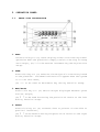
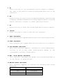
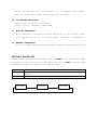
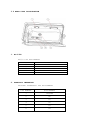
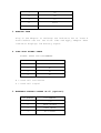
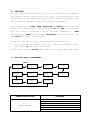
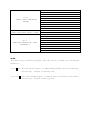
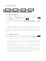
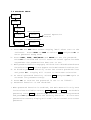
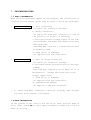
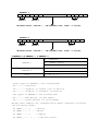
W10 DIGITAL WEIGHING INDICATOR
OPERATION MANUAL
PLEASE READ THIS MANUAL VERY CAREFULLY BEFORE ATTEMPT TO OPERATE
THE SCALE
DECEMBER 2001
Specifications subject to change without prior notice
CONTENTS
1. Introduction
2. Cautions
2.1 Warning
2.2 Power Supply
3. Specifications
4. Installation
4.1 Unpack the unit
4.2 Installation Procedures
4.3 Load Cell Connection
5. Operation Panel
5.1 Front Side Illustration
5.2 Back Side Illustration
6. Setting
6.1 Setting Basic Parameters
6.2 Setting Capacity
6.3 Calibration
6.4 Password Setup
7. Troubleshooting
7.1 Zero Calibration
7.2 Span Calibration
8. Outputs
9. Care and Maintenance
1. INTRODUCTION
The W10 Weighing Indicator utilizes the latest weighing technology
available and it’s equipped with free capacity program. What it
means, you may now set the desire maximum capacity with the division
you like (up to 1/30000). After the parameter setup completes, you
will have an indicator that is tailor made just for you to suit
your application. All setups are simplified and easy to follow,
we hope you will soon start to enjoy it as we have.
FEATURES
Main features include:
•
Setup and calibration procedures are simplified by panel
access.
•
Capable of connecting up to 8 x 350Ω load cells. This makes
the W10 suitable for multi load cells applications.
•
•
Equipped with weight accumulation and memory recall function.
User define semi-auto zero range, zero tracking range and motion
detection can be set according to application requirements.
•
Equipped with serial and RS-232C and parallel output port.
User definable data transmission mode.
•
Two external display output types (RS232C or OP-05) are
available for choice.
•
System parameters and settings are protected by password from
unauthorized access.
2. CAUTIONS
2.1 WARNING
Do not attempt any maintenances or troubleshooting other than those
mentioned in this manual.
To prevent from fire or shock hazard, do not expose the instrument
to rain or any types of moisture.
To avoid electrical shock, do not disassemble the unit. Please
contact your local dealer for more after sale service information.
2.2 POWER SUPPLY
Before plug in the power adaptor to the power outlet, check to make
sure that the input voltage of power adaptor is the same as the
local voltage. If not, do not plug in the adaptor and contact your
dealer immediately.
Recharge the indicator for 8 hours before use for the first time
and recharge it when the low battery signal appears.
3. SPECIFICATIONS
PERFORMANCE
Display: 5
1
/2 digit LCD, 25.4
m
/
m
height
Display Resolution: up to 30,000 count, minimum of 0.1£ gV / div.
Count By: 1, 2, 5, 10, 20, 50
Display Speed: 25 times/second
Zero Adjustment: -2mV to 20mV
Span Adjustment: 0.6mV/V to 4mV/V full scale
Zero Drift: <0.3 µ V/°C (TYP)
Span Drift: 8ppm/°C (TYP)
Non-Linearity: <0.0033% R.O.
Noise Drift: <0.05 µ V p-p (TYP)
Operating Temperature: 0°C ~+40°C
Operating Relative Humidity: <90% non condensing
A/D CONVERTER
Type: 24 bit Sigma-Delta
Resolution: Up to 1,000,000 internal counts
Conversion Rate: 50 times/second
LOAD CELL
Excitation: 5 volts for up to 8 x 350£ [ load cell
Load Cell Connection: 4 Wires ¡ E
] ¡ Ï, E¡ Ð, S¡ Ï, S¡ С ^
INTERFACE
RS-232C: Baud rate, transmission mode selectable
Printer: Centronic type
OP-05: External display
POWER SUPPLY
AC Adaptor: 9V/500mA
Rechargeable Battery: 6V, 4Ah
4. INSTALLATION
4.1 UNPACK THE UNIT
Unpacking the unit carefully. In the package you shall find:
a. This operation manual x 1
b. W10 indicator x 1
c. U shape stand x 1
d. Power adaptor x 1
e. 4 pin load cell connector x 1
*
Keep the packing material for future transportation purpose.
4.2 INSTALLATION PROCEDURES
a. Screw the U shape stand to the indicator
b. Connect the indicator with load cells (junction box).
c. Turn on the indicator and let it warm up for 10 minutes before
commence any setups.
e. Set maximum capacity.
f. Set minimum division.
g. Set the decimal position.
h. Set the zero tracking parameter.
i. Set motion detection parameter.
j. Accomplish zero calibration.
k. Press ON/OFF two times to start operating
4.3 LOAD CELL CONNECTION
In the package, you will find a 4-pin connector for load cell
connection.
Please refer to 5.2 REAR SIDE ILLUSTRATION for how
to connect load cell wires.
5. OPERATION PANEL
5.1.
FRONT SIDE ILLUSTRATION
1. ZERO
Press this key to: (a) reset display value to zero during normal
operation when the platform is empty (refer to setting to setup
zero range), (b) “+” to be used as increment key during function
setup.
2. TARE
Press this key to: (a) subtract the weight of a container placed
on the platform. The TARE indicator will appear when the system
is in the tare mode,
(b) “-“ to be used as decrement key during function setup.
3. NET/GROSS
Press this key to: (a) switch weight displayed between gross
and net weight,
(b) “¡ ö
” to be used for moving the position of cursor to the left
during function setup.
4. PRINT
Press this key to: (a) transmit data to printer via RS-232C or
parallel interface,
(b) “
¡ ÷
” to be used for moving the position of cursor to the right
during function setup.
5. M+
Press this key to: (a) accumulate current weight to memory,
(b) “SET” to be used for entering setup mode when turn on the
indicator.
6. MR
Press this key to recall total accumulated weight result stored
in memory. Accumulated data will be displayed for about 1.5 second
before indicator returns to normal operation status.
7. MC
Press this key to clear the accumulated data stored in memory.
8. ON/OFF
Press this key to turn on and off the indicator.
9. ZERO INDICATOR
This indicator will appear when the scale is at zero weight status.
10.TARE INDICATOR
This indicator will appear when the tare function is in effect.
11.LOW BATTERY INDICATOR
When this indicator appears, recharge the scale immediately.
Failure to do so may cause unrecoverable damage to the
rechargeable battery inside scale.
12.NET, GROSS WEIGHT INDICATOR
This indicator indicates the weight value being displayed is
at net weight or gross weight.
13.WEIGHT UNITS INDICATOR
This indicator appears to indicate the weighing unit being
selected.
SYMBOL DISPLAYED
WEIGHT UNIT
t
Metric ton
H9
Kilogram
lb
Pound
9
Gram
Note: when weight unit selected is “t”, no weight unit symbol
will be displayed under normal operation mode.
14. IN-CHARGE INDICATOR
Red color: Recharging battery
Green color: Charging completed
15. MOTION INDICATOR
This indicator indicates weight detected is not stable. When
this indication is on, M+ and printer function is disabled.
16. MEMORY INDICATOR
This indicator indicates accumulation memory contains of data.
SETTING BACKLIGHT
Under normal operation mode, press and hold ZERO to activate backlight
function. The option will be repeated while ZERO is pressed.
Release the key to obtain the desire mode.
bL.oFF
bL.on1
bL.on2
Disable backlight
Backlight turns off at about 5 seconds after weight is
stabled
Backlight continuously in function
bL.oFF
bL.on1
REPEAT THE CYCLE
bL.on2
5.2 REAR SIDE ILLUSTRATION
1. RS-232C
RS232 PIN ASSIGNMENT
PIN NUMBER
2
3
5
7
8
ASSIGNMENT
RS232 TXD
RS232 RXD
GND
RTS
CTS
2. PARALLEL INTERFACE
PRINTER INTERFACE PIN ASSIGNMENT
PIN NUMBER
ASSIGNMENT
1
STROBE
2
D0
3
D1
4
D2
5
D3
6
D4
7
D5
8
D6
9
D7
11
BUSY
25
GND
3. ADAPTOR JACK
Plug in the adaptor to recharge the indicator for at least 8
hours before use for the first time and apply adaptor when
indicator displays low battery signal.
4. LOAD CELL SIGNAL INPUT
SIGNAL INPUT PIN ASSIGNMENT
PIN NUMBER
ASSIGNMENT
1
E+
2
E-
3
S+
4
S-
E = Load cell excitation
S = Load cell signal
5. EXTERNAL DISPLAY OUTPUT OP-05 (optional)
PIN NUMBER
ASSIGNMENT
1
+5V
2
DATA OUTPUT
3
DATA INPUT
4
NO SIGNAL
6. SETTING
Let the indicator warm up for at least 10 minutes before commence
any setups. Before use for the first time, it is necessary to set
the weight unit, maximum capacity, division, decimal point position,
zero tracking parameter, motion detection parameter.
Utilize the keys of ZERO, TARE, GROSS/NET and PRINT during function
setup to set parameters. When you press M+ for SET, the function
keys will shift to perform a series of under commands e.g. ZERO
for increase, TARE for decrease, NET/GROSS for move curser left
and PRINT for move curser right.
There are two points shall be fully paid attention to:
a. Turn the power on and wait until the indicator displays “W10”,
then press M+ to enter setup mode.
b. Be sure to press ON/OFF twice when all settings are completed.
6.1 SETTING BASIC PARAMETERS
[SET]
1-PAr.
o.r.
modE
bt.
Ut.
Frmt.
0.tr.
mo.d
trA?
mo.t
Prnt
SYMBOL/DEFINITION
SETTINGS
0.r.
(ZERO RANGE)
0 = 0% OF RATED CAPACITY
2 = 2% OF RATED CAPACITY
4 = 4% OF RATED CAPACITY
10 = 10% OF RATED CAPACITY
20 = 20% OF RATED CAPACITY
100 = 100% OF RATED CAPACITY (DEFAULT)
0.0
--0.9
--O.tr.
2.3
(AUTO ZERO TRACKING
2.4
RANGE)
--9.7
9.8
9.9
trA?
0 =
(ZERO TRACKING AFTER TARE) 1 =
0.1
0.2
0.3
--mo.t
(MOTION DETECTION TIME
1.0
INTERVAL)
--9.7
9.8
9.9
= NO TRACKING
= NO TRACKING
= 1.0D PER 1.5 SECONDS
= 1.0D PER 2 SECONDS
= 4.5D PER 3.5 SECONDS
= 4.5D PER 4.0 SECONDS
= 4.5D PER 4.5 SECONDS(MAXIMUM)
DISABLE (DEFAULT)
ENABLE
= 0.1 SECOND
= 0.2 SECOND
= 0.3 SECOND
= 1 SECOND (DEFAULT)
= 9.7 SECOND
= 9.8 SECOND
= 9.9 SECOND (MAXIMUM)
NOTE:
For Auto Zero Tracking Range, the two digits stand for different
meaning.
O.tr.0.0- For the first digit, it means data width of zero tracking.
Unit=0.5D, 0=zero tracking off
O.tr.0.0- For the second digit, it means zero tracking time width.
Unit=0.5S, 0=zero tracking off
SYMBOL/DEFINITION
SETTINGS
0.1 = 0.1 DIVISION
0.2 = 0.2 DIVISION
0.3 = 0.3 DIVISION
--mo.d
(MOTION DETECTION DIVISION 2.0 = 2.0 DIVISION (DEFAULT)
RANGE)
--9.7 = 9.7 DIVISION
9.8 = 9.8 DIVISION
9.9 = 9.9 DIVISION (MAXIMUM)
0.3 = 300 BPS
0.6 = 600 BPS
1.2 = 1200 BPS
bt.
2.4 = 2400 BPS
(BAUD RATE)
4.8 = 4800 BPS
9.6 = 9600 BPS (DEFAULT)
19.2 = 19200 BPS
0 = KEYPAD COMMAND TRANSMISSION
PRESS PRINT TO START DATA TRANSMISSION
1 = AUTOMATIC TRANSMISSION
DATA IS SENT WHEN MOTION STABLIZE
modE
(COMMUNICATION MODE)
2 = COMPUTER COMMAND TRANSMISSION
(INITIATE DATA TRANSMISSION BY GIVING
A COMPUTER READ CR LF COMMAND.
READ CR LF IS DEFINED AS:
R
E
A
D
CR
52H
45H
41H
44H
0DH
LF
0AH
3 = STREAM TRANSMISSION
CONTINUOUS TRANSMISSION (DEFAULT)
SYMBOL/DEFINITION
SETTINGS
lb = POUND
Ut.
t = METRIC TONNE
(WEIGHT UNIT)
g = GRAM
Hg = KILOGRAM
1 = 7 DATA BITS AND 1 PARITY
Frmt
2 = 7 DATA BITS AND 1 PARITY
(DATA TRANSMISSION FORMAT) 8 = 8 DATA BITS AND NO PARITY
9 = 8 DATA BITS AND NO PARITY
0 = PRINT KEY HAS NO FUNCTION, M+ KEY
CAN PRINT. PRESS MC TO PRINT
Prnt
ACCUMULATED VALUE AND CLEAR IT FROM
(PRINTER CONTROL)
MEMORY AT THE SAME TIME.
1 = PRINT KEY HAS FUNCTION, M+ KEY DOES
NOT PRINT.
P.S. NO PRINTING AROUND ZERO, PRINT KEY
FUNCTIONS AS SEQUENCE RESET.
6.2 SETTING CAPACITY
2-CAP
FS.
Ct.
dP
6.2.1 Maximum Capacity
a. Press M+ for SET when screen display “W10” after turn on the
indicator. Press M+ again to enter the parameter setup mode 1-PAr
b. Press ZERO for the next selection 2-CAP
c. Press M+ to enter Maximum Capacity setup
d. Set the maximum capacity by using ZERO, TARE, NET/GROSS and PRINT
keys.
* The Maximum Capacity is the full weight that you want your scale
to handle. This could be the rated capacity of the Load Cell, or
some other limit you wish to set. However, it is also limited by
Mininum Display Resolution since the external resolution is only
1/30000.
6.2.2 Minimum Division
a. Press M+ again to enter the setup for Minimum Division Ct.
b. Change the figure shown on the display by pressing ZERO and TARE.
Minimum Division can be set at 1, 2, 5, 10, 20 or 50.
*
*
*
The Minimum Division is the unit in which the display will be
able to show changes in weight. It bears no relation to decimal
point location.
Resolution is Minimum Division divided by the Maximum Capacity,
and the Minimum Display Resolution of indicator is 1/3000. Be
sure that your setting combination is acceptable by it.
If resolution is set greater than 1/30000. Display will read
“--Erro” after setup the Minimum Division and return of the
previous step to setup the Maximum Capacity.
6.2.3 Decimal Point Position
a. Press M+ again to set decimal point location dP. 0.
b. Change the figure shown on the display by pressing ZERO and TARE.
*
Press M+ again to return of main menu to continue parameter setup
or press ON/OFF twice to start working.
6.3 CALIBRATION
The purpose of calibration is to proof the weight shown on the display
same as real one, hence an accurate weighing result can be obtained.
With Zero Calibration, you can set the weighing result of an empty
weighing device obtained by the indicator as your zero point.
With
Span Calibration, the indicator obtains another weighing result
when a load is placed on the weighing device. The two weighing results
will allow the indicator to adjust the linearity between these two
points as straight as possible intangibly. This gives the indicator
to convert the weight detected precisely and accurately calculating
the weight that lies at any points in between. The closer the Span
Calibration to the maximum capacity is set, the more accurate the
weighing result can be achieved.
In the real world, sometimes it is impossible to calibrate the
weighing device at its maximum capacity weight. But by using a
standard mass at the weight as close as possible to the maximum
capacity possible will be adequate.
The mechanism should be calibrated when you have one of the following
situations;
a. The system is first installed.
b. Any part of the weighing device is changed.
c. If any drifts is detected.
* During calibration, the weighing system must be kept stable for
accurate adjustment.
* Use a high quality standard mass.
6.3.1 Zero Calibration
3-CAL
cAL.-0
00000
Procedures:
a. Press M+ to enter the setup mode when turn on W10.
b. Press ZERO or TARE to select 3-CAL and press M+ to enter calibration
mode.
c. Display will now read cAL.-0 . Wait and confirm that there is
nothing on the weighing platform and the motion detection
indicator is off.
d. Press M+ to perform Zero Calibration.
e. Display will show “. . . .” before it completes the Zero
Calibration.
f. Once Zero Calibration is down, it will move to the next step
and display will show “00000” for Span Calibration.
g. Place the mass on the weighing device and manually key in the
weight of it on the indicator, then press M+ for SET.
h. Display will show “. . . .” before it completes the Span Calibration
and then will return to the main menu.
* If the date input is not acceptable, it will show error messages.
Please refer to the troubleshooting guide for more information about
error messages.
6.4 PASSWORD SETUP
1-PAr
2-CAP
3-CAL
SETUP PASSWORD
4-Pin
00000
Normal Operation
Status
DISABLE PASSWORD
0-PAS
00000
a. Press M+ for SET when screen display “W10” after turn on the
indicator. Press ZERO or TARE to select 4-Pin and press M+ to
enter password setup mode
b. Press ZERO, TARE, NET/GROSS and PRINT to set the password.
Press M+ to confirm and it will return of normal operation mode
regardless the password has been set or not.
c. When password function engaged, calibration is disabled and hence
the selection 3-CAL will not appear on the main menu for selection.
d. To disable password function, enter the correct password first
and press M+. Display will return to main menu selection.
e. To cancel password function, select 4-Pin and press M+ again to
re-enter the password setup.
f. Press M+ to confirm the password is set to as “00000”.
g. Password function is now disabled.
* When password function is enabled, the main menu will only have
3 selections available to enter, 1-PAr , 2-CAP , and 0-PAS . To disable
password, enter 0-PAS by pressing M+ and enter the correct password
and press M+ again to disable the security function. If incorrect
password is entered, display will read “--Erro” and ask to re-enter
password.
7. TROUBLESHOOTING
7.1 ZERO CALIBRATION
When the error messages appear on the display, the calibration is
invalid. Follow theses guide step by step to solve the problems.
1.
A A A A A A A
a. Poor connection
—To check the connector wirings.
b. Wrong connection
—To check the Load Cell Connector to see if
the polarity of signal is reversed.
c. The input offset voltage signal is too low.
—To disconnect the power and insert a resistor
(100–500K ohm)
* Between EXC + and SIG +, a 200K ohm resistor
is normally used.
d. Load Cells is damaged.
—To replace with new Load Cells
2. U U U U U U U
*
a. Poor or wrong connection
—To check the connector wirings.
b. The input offset voltage signal is too high.
(>30mV)
—The Load Cell capacity is too small or it is
malfunction. Change new Load Cells with
bigger capacities.
c. Load Cells is damaged
-To replace with new Load Cells
d. Thunderstorm damage
—To replace a new A/D converter
If there had been inserted a resistor already, use another
resistor with greater resistance.
7.2 SPAN CALIBRATION
If the system is not install for the first time, and the span is
still good, press MC to quit Span Calibration mode and lock all
data of setting.
1. Press M+ after completed Zero Calibration, wait till the display
reads “00000”.
2. Put the weight on the weighing platform and set the figure of
the Span weight on the display by pressing ZERO, TARE, NET/GROSS
and PRINT.
3. Press M+ for indicator to execute the command and it will display
“. . . .” while processing.
4. The Span Calibration is accomplished and all of the setting data
are locked. Display will exit to the next selection on the main
menu.
1.
L L L L L L L
The input signal becomes lower.
—Check the Load Cell connector to see if the
polarity of signal is reversed.
—The platform device has been disturbed.
2.
C C C C C C C
The value of span is too small.
–The value of span is the Maximum Capacity.
But we mentioned above, this might not be always
possible.
3.
- - - - - - -
The output signal of Load Cell is inadequate
for Span Calibration.
—To decrease the Display Resolution.
–To change Load Cells with higher output
signal.
4.
U U U U U U U
a. The input signal is too high (more than
30 mV)
—Replace new Load Cells with
bigger
capacities.
b. Load Cells were damaged.
–To replace with new Load Cells.
c. Poor connection.
—To check the connector wirings.
8. OUTPUTS
A. Specifications:
Type: EIA-RS-232C
Method: Half-duplex, asynchronous transmission
Format: Baud rate: 600, 2400, 4800, 9600 or 19200
Data bit: 7
Parity bit: 1 (EVEN)
Stop bit: 1
Code: ASCII
Stop bit: 1
Code: ASCII
1
0
1
2
3
4
5
6
0
DATA BITS
START BIT
STOP BIT
PARITY BIT
B. Transmission Modes
1. KPC (Keyboard prints control): One weight data reading only will
be transmitted when the W-10 PRINT key is pressed, unless the BUSY
input is low.
2. AUTO: Auto-Print means that data will be transmitted for printing
once per weighing event (resetting when display is < 100D).
3. SM (Stream mode): In stream mode data
will be transmitted
continuously unless the BUSY input is low, when it be stopped.
4. CMD (Command mode): In command mode data will only be sent when
a “READ” command is received from an external device, BUSY input
is invalid.
Refer to 6.1 SETTING BASIC PARAMETERS for transmission mode.
C. Command Mode Timing
TARE, ZERO or NTGS
R x D
300 msec
(Min)
READ
300msec
(Max)
350msec
100msec
600 baud
2400 baud
WEIGHT DATA
T x D
1. READ Command. R x D -----(READ) (CR) (LF)
e.g.
52
45
41
44
OD
OA
R
E
A
D
CR
LF
When this READ command is received, a weight data sample immediately
following the command will be transmitted. No further commands will
be accepted during the 300msec. (Max) delay preceding Weight Data
Transmission or during such transmission (350msec-600 baud or
100msec-2400baud).
2. TARE Command. R x D -------(TARE) (CR) (LF)
When this TARE command is received, the TARE function of the indicator
will be activated. After the 300msec. (Min) delay following TARE
(or ZERO or NTGS), a READ command will be accepted, but do not send
it any sooner. A “TARE Command” (like the TARE key) is invalid if
the weighing platform and weight data samples are unstable.
3. ZERO Command. R x D--------(ZERO) (CR) (LF)
Has the same effect as pressing the ZERO key, invalid, when unstable.
See TARE above for timing.
4. NET/GROSS Command. R x D --------(NTGS) (CR) (LF)
Has the same effect as pressing the GROSS/NET key. See TARE above
for timing.
FORMAT 1
,
HEADER 1
CR LF
,
,
HEADER 2
UNIT
WEIGHING RESULT (INCLUDE +,- AND DECIMAL POINT, TOTAL = 8 DIGITS)
FORMAT 2
,
HEADER 1
CR LF
,
HEADER 2
UNIT
WEIGHING RESULT (INCLUDE +,- AND DECIMAL POINT, TOTAL = 8 DIGITS)
CONTENTS OF HEADER 1 & HEADER 2
OL: OVERLOAD
HEADER 1
ST: STABLE STATUS
US: UNSTABLE STATUS
NT: NET WEIGHT
HEADER 2
GS: GROSS WEIGHT
UNIT
kg, Lb, g, t
Three types of HEADER 1 are transmitted:
OL………………………Overload
ST………………………Display is Stable (not-in motion)
US………………………Display is Unstable (in-motion)
Two types of HEADER 2 are transmitted:
NT………………………Net Weight (in Net Mode)
GS………………………Gross Weight (in Gross Mode)
Weight data samples are transmitted by ASCII numerals including
the following codes:
2D (HEX)………………”
“ (minus)
2B (HEX)………………” + “(plus)
2O (HEX)………………”
“ (space)
2E (HEX)……………… “ , “ (decimal point)
Units are transmitted as: - Kg, “ “g,” “t and LB (“
Terminator” (CR) (LF)
D. DB23S CONNECTOR
25 Pin Connector:
Pin
1
2
3
4
Function FG RXD TXD *
* : Connected.
5
*
6
7
DSR SG
“ –space)
8 20
CD DTR
5. OP-05 External Display
The display shows the weight data only.
* 6 digits: 100 H x 60 W (mm)
* Dimension: 608L x 174.5H x 57.5W (mm)
6. FIXED-TARE DEVICE
*5 digits
*Set fixed-tare function only when “NET” indicator is lighted.
9. CARE AND MAINTENANCE
a. Do not attempt to disassemble the instrument to clean it.
b. Do not submerge the instrument in water, and do not pour or spray
water on it directly.
c. Never use acetone or other volatile solvents such as thinner,
alcohol, etc. to clean your indicator.
d. Clean the instrument with a soft damp cloth and/or a mild detergent
when necessary.