1
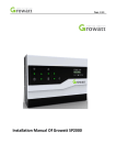
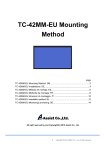
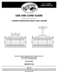
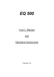
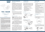
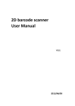
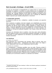
XR130 Beam
PR-2133
This product manual contains important information about the safe installation and use of this projector. Please
read and follow these instructions carefully and keep this manual in a safe place for future reference.
PR LIGHTING LTD.
http://www.pr-lighting.com
1/20
INDEX
3
4
5
6
6
7
7
7
8
10
10
11
13
13
13
13
13
14
17
18
SAFE USAGE OF THE PROJECTOR
INSTALLING THE PROJECTOR
FITTING THE LAMP
POWER SUPPLY – MAINS
CONTROL CONNECTIONS
DMX TERMINATOR
SETUP OPTIONS-PROJECTOR CONFIGURATION
TO SET THE DMX START ADDRESS
OPERATION MENU
ERROR MESSAGE
REPLACING GOBOS
DMX PROTOCOL
LED INDICATION
MAINTENANCE
LUBRICATION
KEEPING THE PROJECTOR CLEAN
TROUBLESHOOTING
TECHNICAL DATA
ELECTRICAL DIAGRAM
COMPONENT ORDER CODES
Please note that as part of our ongoing commitment to continuous product development, specifications are subject to change without notice. Whilst
every care is taken in the preparation of this manual we reserve the right to change specifications in the course of product improvement. The
publishers cannot be held responsible for the accuracy of the information herein, or any consequence arising from them.
Every unit is tested completely and packed properly by the manufacturer. Please make sure the packing and / or the unit are in good condition before
installation and use. Should there be any damage caused by transportation, consult your dealer and do not use the unit. Any damage caused by
improper use will not be assumed by the manufacturer and / or dealer.
ACCESSORIES
These items are packed together with the projector:
Name
G clamps
XLR connector
Safety cord
Power Cable
Power-Con
User’s manual
Ω clamps
Quantity
2
1
1
1
2
1
2
Unit
Pcs
pc
Pc
pc
Pcs
Pc
Pcs
2/20
Remark
without DMX cable
Male and Female one each
Optional
SAFE
E USAGE
E OF THE PROJEC
CTOR
When unpackinng and before disposing
W
d
of the carton check thhere is no transp
portation damaage before usingg the projector. Should there bee
a damage cauused by transporrtation, consult your dealer andd do not use thee apparatus.
any
The projector iss for indoor usee only, IP20. Use
T
U only in dryy locations. Keeep this device away
a
from rainn and moisture, excessive heatt,
h
humidity
and duust. Do not allow
w contact with water
w or any othher liquids.
T projector is not designed or
The
o intended to bee mounted direcctly on to inflam
mmable surfacess.
T projector is only intended for
The
f installation, operation and maintenance
m
by
y qualified persoonnel.
The projector must
T
m be installeed in a locationn with adequatte ventilation, at
a least 50cm from
f
adjacent w
wall surfaces. Be
B sure that noo
v
ventilation
slots are blocked.
D not project thhe beam onto innflammable surrfaces, minimum
Do
m distance is 3m
m.
A
Avoid
direct expposure to the ligght from the lam
mp. The light is harmful to the eye.
e
D not attempt to
Do
t dismantle annd/or modify thee projector in anny way.
E
Electrical
conneection must onlyy be carried outt by qualified peersonnel.
B
Before
installatiion, ensure that the voltage andd frequency of power
p
supply match
m
the powerr requirements oof the projector.
I is essential thaat each projectoor is correctly eaarthed and that electrical
It
e
installaation conforms to all relevant sstandards.
D not connect this device to any
Do
an other types of
o dimmer appaaratus.
Make sure that the power-cordd is never crim
M
mped or damageed by sharp edg
ges. Never let the
t power-cord ccome into contactt with other cabless.
O handle thee power-cord byy the plug. Neveer pull out the plug
Only
p by tugging the power-cordd.
K the lamp clean.
Keep
c
Do not toouch the lamp glass
g with bare hand.
h
The projector shhould always bee installed with a secondary saafety fixing. A safety
T
s
cord is suupplied for this; it should be atttached as shownn
inn “installing thee projector” secction.
Shields and lenss shall be changged if they havee become visiblyy damaged to su
S
uch an extent thhat their effectivveness is impairred, for examplee
b cracks or deeep scratches.
by
E
Exterior
surfacee temperatures of
o the luminairee after 30 minutees operation is 70℃,
7
when steaady state is achiieved 90℃,
T
There
is no userr serviceable parrts inside the prrojector, do not open
o the housin
ng and never opperate the projecctor with the cov
vers removed.
I you have any questions or suuggestions, don’’t hesitate to connsult your dealeer or manufactuurer
If
Always discconnection from
A
f
Power,
r, when the device not in
i use or beefore cleanin
ng or any maintenance
m
e
w
work
!
3/20
INSTALL THE PROJECTOR
Safety Cord
! WARNING
Please run safety cord
through safety hook
Safety Hook
106
Handle
Digital
Control Panel
Take 2 clamps and the safety cord out from the package and mount 2 clamps on the underside of fixture with 2 retainers attached to each
clamp. Hang the fixture on the structure and fasten the screws attached to each clamp. (See the WARNING on the underside of the base
as shown above) To pass the SAFETY CORD through the HOLES for safety! Always ensure that the projector is firmly anchored to
avoid vibration and slipping whilst functioning. Always ensure that the structure that you are going to mount the projector to is secure and
strong enough to support the weight of a XR 130 Beam
WARNING:
1. The projector MUST be lifted or carried by the HANDLES instead of clamps.
2. For safety the safety cord should afford 10 times the Projector’s weight.
4/20
FITTING THE LAMP
Lock the yoke before fitting/replacing the lamp just as Shown by Figure 2, after Opening the head’s cover of a projector by loosening
4fastfit screws.
Pull out the lamp from the bottom of the head after rotating it anti-clockwise after holding the lamp’s bottom.
Installation and removal are in reverse orders.
Tighten the 4 fastfit screws after the cover is installed.
Note: don’t touch the bulb of the new lamp with bare hands so as not to impair the beam output.
Important: Always read "Instructions for use" enclosed with the lamp.
2.Take the lamp out after pushing
it down after loosening the 2
spring screws
1.Manually loosen the 2 spring screws
DMX
PR-2133
XR 130 Beam
5/20
POWER SUPPLY-MAINS
Connect the power cord as follows:
L (live) =brown
E (earth) =yellow/green
N (neutral) =blue
Before connection with mains power, make sure that the voltage and frequency marked on the rating plate of the projector match what
are supplied. It is recommended that each projector be supplied separately so that they may be individually switched on and off.
NOTE: If the fixtures’ power outputs and inputs are connected in series, please connect the first fixture’s power input with the external
power supply, and connect its power output with the second fixture’s input and so on till all the fixtures are connected. If the supplied
voltage is 200V~240V, the maximum number of fixtures connected is 10pcs. If it is 100V~120V, the maximum is 8pcs. The diameters of
the wires for the power input and output cables must be equal or bigger than 2.5 mm2.
IMPORTANT
It is essential that each projector is correctly earthed(yellow/green twin wire) and the electrical installation conforms to all
relevant standards.
CONTROL CONNECTION
Connection between controller and projector and between one projector and another must be made with a twin-screened cable, with each
wire having at least a 0.5mm in diameter. Connection to and from the projector is via cannon 5 pin (which are included with the projector)
or 5 pin XLR plugs and sockets. The XLR's are connected as shown in the figure above.
Note: care should be taken to ensure that none of the pins touch the metallic body of the plug or each other. XLR plugs and sockets
mustn’t be connected in any way other than mentioned in the above figure. The XR 130 Beam accepts digital control signals in protocol
DMX512 (1990).
Connect the controller’s DMX output to the first fixture’s DMX input, and connect the first fixture’s DMX output to the second fixture’s
DMX input and connect the rest fixtures in the same way. Eventually connect the last fixture’s DMX output to a DMX terminator as
shown in the figure below.
6/20
DMX TERMINATOR
In the Controller mode, at the last fixture in the chain, the DMX output has to be connected with a DMX terminator. This prevents
electrical noise from disturbing and corrupting the DMX control signals.
The DMX terminator is simply an XLR connector with a 120Ω (ohm) resistor connected across pins 2 and 3, which is then plugged into
the output socket on the last projector in the chain. The connections are illustrated below.
DMX TERMINATOR
2
1
3
120
CONNECTION
Connect a 120 (OHM) resistor
across pins 2 and 3 in an XLR plug
and insert into the DMX out socket
on the last unit in the chain.
PIN 2
PIN 3
SETUP OPTIONS-PROJECTOR CONFIGURATION
Projector configuration can be set conveniently via push button and LCD display.
Launch the projector and press button ENTER for more than 5 seconds to unlock the panel, the LCD will show the function menu of the
projector, each main menu has its submenus and each submenu has a specific function. For details, please see the
“OPERATION MENU” section.
Press button UP or DOWN if you want to browse through the various Setup Options.
Press button ENTER to save your settings or enter the submenu.
Press button UP or DOWN to change values(plus or minus)
Press button FUNC, it will return to the upper menu. If button FUNC not pressed, the default will show display status automatically.
TO SET THE DMX START ADDRESS
Each XR 130 Beam must be given a DMX start address so that the correct projector responds to the correct control signals. This DMX
start address is the channel number from which the projector starts to “listen” to the digital control information being sent out from the
controller. The XR 130 Beam has 2 DMX modes. There are standard and short modes. For example standard mode has 16channels, so
set the No. 1 projector’s address 001, No. 2 projector’s address 017, No. 3 projector’s address 033,and No. 4 projector’s address is
049,and so on.
Launch the projector. Press button ENTER more than 5 seconds to unlock panel.
Press button ENTER to display DMX address;
Press button UP and DOWN, you can set the address;
Press button ENTER to confirm; after powered on next time, the default will be last value saved
Press button FUNC, it will return to the upper menu.
7/20
OPERATION MENU
First Menu
Secondary Menu
Third Menu
DMX Address
XXX
(XXX:1~497)
Short 1~501
Standard 1~497
Reset
Are You Sure
Standard16
DMX Channel Mode
(Default:Standard)
Short 12
When DMX is Lost
Normal Time out
When DMX is Lost
Hold Last value
Loss of DMX
By Control Channel
Config Settings
Lamp Control
By Power On
By DMX Present
Pan Calibration
0~127
Tilt Calibration
0~127
Parameter Transm
YES
Factory Settings
YES
Color Positions
Steeped
Color Positions
Linear
Pan DMX Invert
OFF
Pan DMX Invert
ON
Tilt DMX Invert
OFF
Tilt DMX Invert
ON
Pan Tilt Swap
OFF
Pan Tilt Swap
ON
Dimmer Invert
OFF
Dimmer Invert
ON
Color Wheel Positions
Pan DMX Invert
Tilt DMX Invert
Option Settings
Pan Tilt Swap
Dimmer Invert
Pan Angle Range
360 / 720
Defaults
YES
English
Language
Chinese
Display
On Always
Display
Off After Delay
Display Invert
OFF
Display Invert
ON
Display Mode
Display Options
Display Invert
Display Dimming
1~10
Display Contrast
Display Contrast
XX(1~18),default 9
8/20
Fourth Menu
Lamp Hours
Hours:xx
Reset Lamp Hours
Are You Sure
Total Hours
Hours:xx
Temperature
Temperature
XX℃
Information
Display Board
Software Version
Fan Board
DMX Channel
1=XXX
Electronic SN=
********
View DMX Values
Electronic SN
Test Modes
Lamp Manual Control
Wireless Options
(Optional)
Display Board=
X.X.X
Fan Board=
X.X.X
Self Test
Yes
Turn Lamp On
Yes
Turn Lamp Off
Yes
Wireless Mode
Wireless Mode
XLR First
Wireless Mode
Wireless First
Wireless Mode
Wireless Only
Wireless Mode
XLR Only
Wireless Mode
Wireless To XLR
Un-Link Wireless
YES
DMX Mode
YES
Preset Memory
YES
User Memory
YES
Master Mode
Strobe
Dimmer
Color wheel
Operation Mode
Memory Edit
Static Scene
(1~16 scenes)
Rotating
Gobo Wheel
Gobo
Rotation
Effect Wheel
Settings
Prism
Rotation
Focus
Slave Mode
Pan Location
Pan
Tilt Location
P&T Speeds
Hold Time
9/20
ERROR MESSAGES
In the course of launch, Projector examines automatically whether there are errors and if there are, it will display
information as follows:
Head Fan 1 Fail
Head Fan 2 Fail
REPLACING GOBOS
Disconnect from power ,loosen 4 fastfit screws of the side cover, and open the cover as shown by the figure below.
Replace an old gobo of the rotating gobo wheel with a new gobo.
Tighten the 4 fastfit screws after the side cover is put back.
Snap rings
Gobo
DMX
PR-2133
XR 130 Beam
10/20
DMX PROTOCOL
Short
mode
1
2
3
4
Standard
mode
1
2
3
4
Extended
Mode
FUNCTION
Strobe
Dimmer
Color Wheel
Rotating Gobo
Wheel
11/20
DMX
DESCRIPTION
000-010
Close
011-025
Open
026-225
Strobe speed from slow to fast
226-239
Macro 1
240-241
Macro 2
242-246
Macro 3
247-255
Open
000-255
Linear dimming
000-008
White
009-016
Color 1
017-024
Color 2
025-032
Color 3
033-040
Color 4
041-048
Color 5
049-056
Color 6
057-064
Color 7
065-073
Color 8
074-082
Color 9
083-091
Color10
092-100
Color11
101-109
Color12
110-118
Color13
119-127
CTO
128-191
Rotation ,Clockwise from slow to fast
192-255
Rotation, Anti-clockwise from slow to fast
000-017
White
018-027
Gobo 1
028-037
Gobo 2
038-047
Gobo 3
048-057
Gobo 4
058-067
Gobo 5
068-077
Gobo 6
078-087
Gobo 7
088-097
Gobo 8
098-107
Gobo 9
108-117
Gobo 10
118-127
Gobo 11
128-147
Rotation (Clockwise From slow to Fast)
148-167
Rotation (Anti-clockwise From slow to Fast)
168-175
Shake of Gobo 1 from slow to fast
176-183
Shake of Gobo 2 from slow to fast
184-291
Shake of Gobo 3 from slow to fast
192-199
Shake of Gobo 4 from slow to fast
200-207
Shake of Gobo 5 from slow to fast
208-215
Shake of Gobo 6 from slow to fast
216-223
Shake of Gobo 7 from slow to fast
224-231
Shake of Gobo 8 from slow to fast
232-239
Shake of Gobo 9 from slow to fast
240-247
Shake of Gobo 10 from slow to fast
248-255
Shake of Gobo 11 from slow to fast
000-128
5
5
6
6
7
7
8
Gobo Rotation
Gobo Rotation
Fine
Effect Wheel
Prism Rotation
Gobo Indexing (0°-540°)
129-188
Rotation (Clockwise From slow to Fast)
189-195
Stop
196-255
Rotation (Anti-Clockwise From slow to Fast)
000-255
Gobo Rotation in 16 Bit
000-063
White
064-127
Prism
128-191
Deep Frost
192-255
Light Frost
000-128
Stop
129-191
Rotation(Clockwise from slow to fast)
192
Stop
193-255
Rotation(Anti- Clockwise from slow to fast)
8
9
Focus
000-255
Linear Focusing
9
10
Pan
000-255
Pan(0°~720°)
11
Pan Fine
000-255
Pan in 16 bit precision
000-127
Stop
128-191
Rotation (Clockwise From slow to Fast)
192-255
Rotation (Anti-Clockwise From slow to Fast)
10
11
12
12
Continuous Pan
13
Tilt
000-255
Tilt(0°~270°)
14
Tilt Fine
000-255
Tilt in 16 bit precision
15
Pan & Tilt Speeds
000-255
Pan & Tilt Speed from Fast to Slow
000-047
Reserved
048-080
Reset
081-112
Reserved
113-144
Lamp Off ( Delay for 3 s)
145-168
Reserved
169-200
Lamp Full Power
201-223
Reserved
16
Control
Lamp Full Power
224-255
Remark:
If you intend to turn on/off the lamp via the last channel of the controller, don’t attempt to push the channel to value
224-255 immediately after turning it off, or push the slide bar to value 224-255 to wait it cooling. Under these 2
circumstances, the lamp can not be turned on. The right operation is: turn it off---cool down---push the slide bar to turn it
on.
12/20
LED INDICATION
On
Off
Flash
On
Off
Flash
Green LED indication
Blue LED indication
DMX signal OK
No DMX signal
DMX signal error
Wireless Signal OK
Not linked with any transmitters
Loss of connection or being linked with a transmitter
MAINTENANCE
If the projector’s lens becomes damaged or broken it should be replaced. If the lamp becomes damaged or deformed in any way it must
be replaced. If the light from the lamp appears dim this would normally indicate that it is reaching the end of its life and it should be
changed at once, aged lamps run to the extremity of their life might explode. If the projector does not function, check the fuses on the
power socket of the projector, they should only be replaced by fuses of the same specification. The projector has overheat protection
device that will switch off the projector in case of overheating. Should it happen, check if the fans are blocked or not, or if they are dirty,
clean them before switching on the projector again.
Any maintenance work should only be carried out by qualified technicians.
LUBRICATION
To ensure the smooth rotation of the rotating gobos and movement of the lens for focusing, it is recommended that the bearings for the
rotating gobos and the 2 sliding tracks for the focusing lens holder be lubricated every two months. Use only high quality,
high-temperature grease .
KEEPING THE PROJECTOR CLEAN
To ensure the reliability of the projector it should be kept clean. It is recommended that the fans should be cleaned every 15 days. The
lens and dichroic colour filters should also be regularly cleaned to maintain an optimum light output. Do NOT use any type of solvent
containing chemical elements on dichroic colour filters.
Cleaning frequency depends on the environment in which the fixture operates. A soft cloth and typical glass cleaning products should
be used in cleaning. It is recommended to clean the external optics at least once every 20 days and clean the internal optics at least once
every 30 / 60 days.
Do not use any organic solvent, e.g. alcohol, to clean the reflector mirror, dichroic colour filters or housing of the apparatus.
TROUBLESHOOTING
PROBLEM
The projector doesn’t switch on
The lamp is on but the projector doesn’t respond
to the controller
The projector functions intermittently
Beam appears dim, Low in brightness
The project image appears to have a halo
Heavily Defective Beam
ACTION
¾
¾
¾
¾
¾
¾
¾
¾
¾
¾
Check the fuse on the power socket.
Check the lamp.
Make sure that the fixture’s start address is right
Replace or repair the XLR signal cable.
Make sure the fan is working well or fans and their shields are not blocked
Make sure the lamp is within its lifespan
Remove dust or grease from the lenses.
Carefully clean the lamp, optical lenses and other components.
Check if lens are in good condition(not cracked)
Clean dust or grease on the lens.
13/20
TECHNICAL DATA
VOLTAGES:
100V~240V AC,50/60Hz
POWER CONSUMPTION:
240W@220V
LAMP:
OSRAM
Colour Temperature
SIRIUS HRI 132W
8800K
Manufacturers Rated Lamp Life
6000hours
COLOURS:
1 Color Wheel:13colors +CTO+white
Optional Stepping/linear color changing
ROTATING GOBO WHEEL
1Rotating Gobo Wheel: 11 gobos(8pcs rotatable)+ white
Shake effects with variable speeds, bi-directional wheel scrolling at variable speeds
Gobos replaceable
Gobos’ outer size: ¢11.8mm
Gobos’ Image size: ¢6mm
EFFECT WHEEL :
1pc,8-facet rotating Prism(bi-directional with variable speeds)+ 1Deep Frost filter +1light Frost filter+White
FOCUS:
Linear focusing
DIMMER:
linearly adjustable
STROBE:
Double shutter blades, 0.3~25 F.P.S with macros
HEAD MOVEMENT:
Continuous Pan movement, Tilt 270º with auto position correction
BEAM ANGLE:
0°~ 3°
14/20
CONTROL:
DMX512, 3-pin and 5-pin interfaces
RDM Protocol
12 channels in short mode, 16channels in standard mode
Self-test mode
OTHER FUNCTIONS:
Adjustable Pan & Tilt speed
The display for the fixture’s and the lamp’s hours respectively
English and Chinese LCD display with its brightness and contrast adjustable
Energy saving ballast
Auto-Diagnosis by Sensors
Isolated Input DMX signal
Modular Structure for easy maintenance
HOUSING:
High temperature ABS, IP20
NET WEIGHT:
13.2Kg
15/20
SIZES:
303.6
421.9
442.4
271
DMX
DMX
PR-2133
XR 130 Beam
PR-2133
XR 130 Beam
312
280
LIGHT OUT:
0
416352
104088
0m
0
5m
0.27
10m
0.54
46261
26022
16654
11565
3°
3.0°lux
Disrance(m)
3.0°Diameter(m)
15m
0.81
16/20
20m
1.08
25m
1.35
30m
1.62
Electrical Diagram:
17/20
Component Order Code
NAME
PAN MOTOR
TILT MOTOR
STROBE MOTOR
COLOR WHEEL MOTOR
ROTATING GOBO WHEEL MOTOR
GOBO ROTATION MOTOR
PRISM ROTATION MOTOR
EFFECT WHEEL MOTOR
FOCUS MOTOR
TURBO- FAN
LAMP FAN
FAN IN BASE BOX
ELECTRONIC BALLAST OSRAM
LAMP OSRAM
ROTATING GOBO WHEEL
ACCESSORY
COLOR WHEEL ACCESSORY
EFFECT WHEEL ACCESSORY
POWER SWITCH
THERMAL SENSOR
PAN / TILT DRIVER BOARD
LCD MASTER BOARD
FAN DRIVER BOARD
MOTOR DRIVER BOARD
TILT BELT
PAN BELT
EFFECT WHEEL IN/OUT BELT
GOBO ROTATION BELT
FOCUS BELT
PRISM ROTATION BELT
PRISM IN/OUT BELT
PART NO.
QUANTITY
030040174
2
030040220
3
030040222
1
030040236
2
030040154
030040116
030060072
030060055
030060069
040070120
100070036
1
2
1
1
2
1
1
120110685
1
120110663
1120110684
190010185
190010171
230060356
230060357
230060358
230060359
290151389
290151390
290151396
290151409
290151410
290151411
290151412
1
1
1
1
1
1
1
1
1
1
1
1
2
1
1
18/20
REMARK
19/20
PR LIGHTING LTD.
1582 Xingye Avenue, Nancun Panyu
Guangzhou, 511442 China
TEL: +86-20-3995 2888
FAX: +86-20-3995 2330
P/N: 320020264
Version: 20150127 (Preliminary)
20/20