1
Technical
Information
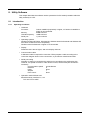
Direct Drive Motor <LINEARSERV>
Intelligent Drive <DrvPIII>
Technical Information
TI 71M02D04-01EN
TI 71M02D04-01EN
Yokogawa Electric Corporation
10th Edition:2012.12.01
Blank Page
i
Introduction
Overview of This Manual
This manual provides information about LINEARSERV, a direct drive servo motor. Make sure
to refer to this manual when you use the motor.
Trademark
•
•
•
•
Windows and Windows NT are registered trademarks of Microsoft Corporation in the
United States and/or other countries.
Adobe and Acrobat are trademarks of Adobe Systems Incorporated.
Pentium is a registered trademark of Intel Corporation in the United States.
Other company and product names mentioned herein may be the trademarks or
registered trademarks of their respective owners.
Copyright
The copyright of this manual belongs to Yokogawa Electric Corporation.
No part of this document may be reproduced, or transferred, sold or distributed to the third
party.
Strategic Goods Advisory
It is required to obtain approval from the Japanese government to export goods regulated by
the Foreign Exchange and Foreign Trade Control Law from Japan.
TI 71M02D04-01EN 10th Edition: 2012.12.01
ii
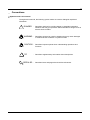
Conventions
Symbols used in this manual
Throughout this manual, the following symbol marks are used to distinguish explained
information.
!
DANGER : Describes cautions for avoiding danger in potentially hazardous
situations that may put operators' lives and bodies in danger such as
electric shock accident.
WARNING : Describes points to be noted in situations that may cause damages
to software and/or hardware or system troubles.
CAUTION : Describes important points when understanding operations and
functions.
TIP
:
Describes supplementary information about descriptions.
SEE ALSO : Describes items and pages that should be referenced.
TI 71M02D04-01EN 10th Edition: 2012.12.01
iii
Precautions
Precautions Regarding this Manual
•
•
•
•
•
•
Please make sure this manual is made available to all end users.
Do not operate the product before reading this manual and thoroughly understanding
its contents.
This manual was created to provide detailed explanations of the functions offered by
the product. It is not guaranteed that it will suit any particular purpose a customer
might have.
The reproduction or copying of any portion of this manual is strictly prohibited without
prior permission from Yokogawa Electric.
The information provided in this manual is subject to change without notice.
If you have any questions or find any errors and/or omissions in the information
provided in this manual, please contact our Sales Department or the dealer from
whom the product was purchased.
Precautions Regarding Protection, Safety and Product Modification
•
•
•
•
•
•
To ensure your protection and that of the product, as well as the systems that use the
product, please observe all safety instructions and other precautions listed in this
manual.
If you operate the product in a manner contrary to the instructions provided in this
manual, the safety protection may be lost. In such an event, we make no warranties
for the quality, performance, functions and safety of the product.
If you install protection/safety circuits for the product or systems that use this product,
make sure to install them on the product separately and externally. Do not install them
inside the product, nor should any internal parts of the product be modified in order to
do so.
Be sure to replace any parts and consumables of the product with parts specified by
us.
This product is neither designed nor manufactured to be used under conditions that
may directly affect the safety of humans including in nuclear or radiation-related
devices, railway facilities, aircraft instruments, marine instruments, air-navigation
facilities or medical devices. If it is necessary to apply the product in systems that
directly affect the safety of humans, it is the user's own responsibility to construct a
system for securing the safety of humans with devices and equipment other than the
applicable product.
Modification of the product is strictly prohibited.
Product Disclaimer
•
•
We make no warranty for the product except as prescribed by the guarantees.
We assume no responsibility for damages any user or third party may incur through
use of the product, nor for any direct or indirect damages that the user or a third party
may incur due to product defects that cannot be predicted by us, etc.
TI 71M02D04-01EN 10th Edition: 2012.12.01
iv
Software
•
•
•
•
•
We make no warranties for the software except as prescribed by the guarantees.
Copying and use of the software for any purpose other than as intended by us, such
as for use as a backup, is strictly prohibited.
Keep the original storage media of this software in a safe place. If you do not have
the original media, we may decline to offer our prescribed quality warranty and
maintenance services.
Reverse engineering of the software, including reverse compilation and reverse
assembly, is strictly prohibited.
The transfer, exchange or subleasing of any part of the software for unwarranted use
by a third party is prohibited without prior permission from Yokogawa Electric.
TI 71M02D04-01EN 10th Edition: 2012.12.01
v
General Precautions Regarding LINEARSERV
•
•
•
•
•
•
•
•
•
•
Never install the motor in reverse, such as by fixing the slider of the motor and
making the mounting plate move.
When removing the drive's side panel to set jumpers or other items, be sure to turn
the power supply OFF before doing so. It is dangerous to touch the high-voltage parts
inside the unit.
Be sure to ground the ground terminal to the earth.
The clearance between the slider and the mounting plate is approximately 0.1 mm.
Dirt or foreign substances adhering to the mounting surface may cause failures.
Prepare a fixture on the load side for the cables that connect to the connectors of the
slider, or fix them on the slider side using the cable attachment screws of the slider,
etc., so that external force is not applied to the connectors. Failure to do so may lead
to disconnection or breakdown.
The optional cables provided by Yokogawa are consumables and have a limited life.
Be sure that the mounting screws of a load never reach or exceed the effective screw
depth of the slider.
The motor's surface is magnetized. Keep objects that are affected by magnetism
away from the motor.
The motor structure is not resistant to dust, splashing or water (oil). When mounting
the motor, please refer to the section "Specification/Installation, Precautions for
Transportation and Storage" in this manual. Foreign substances and grease entering
the encoder unit may cause malfunction and failure.
The motor unit contains glass materials. Avoid subjecting it to vibration and impact.
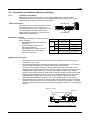
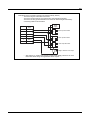
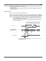
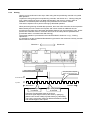
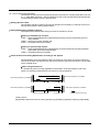
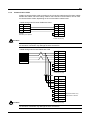
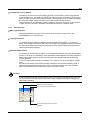
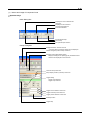
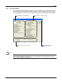
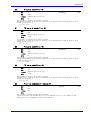
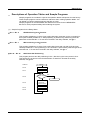
Stopper
Base core surface
Guide unit
Base
Slider Connectors
Slider load mounting surfaces
Base mounting surface
Cable attachment screws
Figure viewed from the connector side
•
The motor mounting plate of a product whose surface treatment suffix code is "N" is
coated to prevent rust. Prior to mounting, wipe the coating of the base mounting
surface completely with petroleum or chlorine solvent. If any coating remains,
mechanical precision and function may be impaired. Please see the section
"Installation" in this manual.
TI 71M02D04-01EN 10th Edition: 2012.12.01
vi
•
•
•
•
•
•
•
•
•
•
•
•
•
•
The stopper in the motor is not intended to absorb impact during operation. Please
prepare separate equipment for protection/safety procedures, such as a stopper and
shock absorber. Refer to the section "Specification/Installation, Precautions for
Transportation and Storage" in this manual.
Be sure not to interfere with the movable area, including the load part, while the motor
is operating. You may be injured if a hand is placed between the slider and the
stopper, or if the movable part is touched.
The guide unit requires grease for lubrication. Driving the motor under insufficiently
lubricated conditions may lead to damage and failure. Please see the section
"Maintenance/Inspection" in this manual.
If you use the screw holes located above and below the box of the DrvPIII drive, be
certain the tips of the screws penetrate no more than 8mm for the 500W and 2kW
classes, or 6mm for the 4kW class, below the drive's surface. If this precaution is not
observed, it may cause an electric shock, short circuit and/or damage to the motor.
The drive should be installed on an appropriate metal cabinet, observing the safety
measures prescribed by the Low Voltage Directive and EMC Directives.
Interchangeability between motors and drives is possible only if the drive and the
motor are compatible. In other words, the LINEARSERV motor's three-digit model
code (LM) must match that of the drive (UM1LP3-) if you wish to change
the combination and use the motor with a different drive unit.
In the LINEARSERV series, each motor has been tuned to operate with a specific
head amplifier. If the combination is different, the motor may not operate normally, or
one or more devices may be damaged. Please combine and use a motor and head
amplifier having the same model code, serial number and slider number.
If the product is installed in such a way that cables are bent in the machine, etc., be
sure the minimum bend radius of the cable is 50mm or more. Moreover, do not install
cables such that they are bent repeatedly. It may cause disconnection and failure.
Do not conduct over-voltage tests. Circuitry in the drive or motor may become
damaged as a result of these types of destructive tests.
Never attempt to disassemble or modify the motor or drive. We assume no
responsibility if you disassemble or modify them.
Disconnect all power and wait 7 minutes before servicing. May cause electric shock.
The high voltage is applied to the regenerative resistor terminal. In general, it is
necessary to wait 7 minutes for 2kW and 4kW classes or 4 minutes for 500W class
until the voltage lowers to the safe level after powering off.
Do not remove the separator attached in the regeneration resistor terminal of a drive.
The separator is attached to the model with which the regeneration resistor is not
supplied so that regeneration resistor may not be connected accidentally, and so that
it cannot touch carelessly.
If the motor moves in repeated reciprocating motion less than 20mm stroke, carry
shakedown cruise for 50mm or longer over 10 times by every 10,000 reciprocating
motions.
Prepare a fixture in the control panel or on the machine, fix the cables to the fixture
near the connectors, so that external force is not applied to the connectors.
TI 71M02D04-01EN 10th Edition: 2012.12.01
vii
•
•
•
•
A part of machine parameters overwrites the related parameters when the power is
recycled, if those parameters are changed. “10.0x (Data Sum Error)” may rarely occur
in case that the control power supply is terminated before LED for RDY signal is
lighted when the power is recycled. If this error occurs, restore user data, which was
backed up beforehand, after initialization of user parameters (Backed up parameter
values are set).
Make sure not to terminate control power supply while All-Reset function is in
execution. All-Reset needs more 5 (five) seconds for the completion. “10.0x (Data
Sum Error)” may occur in case that the control power supply is terminated in this
while. Execute All-Reset again if the error occurs.
Utility software includes several functions, which recycle AC main power automatically.
“10.0x (Data Sum Error)” may rarely occur in case that the control power supply is
terminated before LED for RDY signal is lighted when the power is recycled. If this
error occurs, restore user data, which was backed up beforehand, after initialization of
user parameters (Backed up parameter values are set).
If you turn off the power after the occurrence of overload error, please turn on the
power after more than 10min. If this error occurs again, please review the operating
conditions.
TI 71M02D04-01EN 10th Edition: 2012.12.01
Blank Page
TOC-1
Table of Contents
Introduction ............................................................................................................................................... i
Conventions ............................................................................................................................................. ii
Precautions ............................................................................................................................................. iii
1.
Overview of the Product ...................................................................................................................... 1-1
2.
1.1
LM Series Motor ........................................................................................................................... 1-1
1.2
DrvPIII Drive ................................................................................................................................. 1-1
1.3
Checking the Product ................................................................................................................... 1-2
Specifications ........................................................................................................................................ 2-1
2.1
Standard Specifications ................................................................................................................ 2-1
2.2
Thrust/Velocity Characteristics ..................................................................................................... 2-5
2.3
Model and Suffix Codes ............................................................................................................... 2-6
2.4
Option Cables ............................................................................................................................. 2-10
2.4.1
2.4.2
2.4.3
2.5
Outline Drawings ........................................................................................................................ 2-15
2.5.1
2.5.2
2.5.3
2.5.4
2.5.5
2.5.6
2.5.7
2.6
3.
Servo-Deceleration ........................................................................................................... 2-27
Dynamic Brake (with selection -1B) ................................................................................. 2-29
Example............................................................................................................................ 2-30
Operating Restrictions ................................................................................................................ 2-32
2.8.1
2.9
2.6.1 Installation of the Motor ........................................................................................... 2-23
Installation of the Drive ..................................................................................................... 2-25
Stop Function in Error State ....................................................................................................... 2-27
2.7.1
2.7.2
2.7.3
2.8
Motor ................................................................................................................................ 2-15
Head amplifier .................................................................................................................... 2-2
Drive ................................................................................................................................. 2-20
Regenerative resistor ....................................................................................................... 2-21
Connector ......................................................................................................................... 2-21
Terminals .......................................................................................................................... 2-22
Motor Filter ....................................................................................................................... 2-22
Precautions at Installation, Moving and Storage ........................................................................ 2-23
2.6.1
2.6.2
2.7
Option Cable Model and Suffix Code ............................................................................... 2-10
Recommended Cables ..................................................................................................... 2-13
Cable Specifications ......................................................................................................... 2-14
Restrictions on the Number of EEPROM Registrations ................................................... 2-32
Conformed Standards ................................................................................................................ 2-33
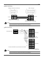
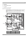
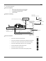
System Configuration .......................................................................................................................... 3-1
3.1
System Configuration ................................................................................................................... 3-1
3.2
Contact I/O Interface .................................................................................................................... 3-2
3.2.1
3.3
Contact I/O ......................................................................................................................... 3-2
CC-Link Interface .......................................................................................................................... 3-3
3.3.1
What is CC-Link?................................................................................................................ 3-3
TI 71M02D04-01EN
10th Edition: 2012.12.01
TOC-2
3.3.2
3.3.3
4.
Name and Function of Each Part ........................................................................................................ 4-1
4.1
Motor Unit ..................................................................................................................................... 4-1
4.2
Drive Unit ...................................................................................................................................... 4-2
4.2.1
4.2.2
4.2.3
5.
Network Configuration ........................................................................................................ 3-4
Communication................................................................................................................... 3-5
500W Class ........................................................................................................................ 4-2
Explanation of the Front Panel (Connect I/O) .................................................................... 4-3
Explanation of the Front Panel (CC-Link) .......................................................................... 4-4
Wiring ..................................................................................................................................................... 5-1
5.1
Overall Connection ....................................................................................................................... 5-1
5.1.1
5.1.2
5.1.3
5.1.4
Connection Diagram ........................................................................................................... 5-1
Circuit Protector .................................................................................................................. 5-2
List of Recommended Parts ............................................................................................... 5-2
List of Cable Specifications ................................................................................................ 5-3
5.2
Main Power Supply/Control Power Supply Terminal <TB1> ........................................................ 5-4
5.3
Motor Terminal/Ground <TB2>..................................................................................................... 5-5
5.4
Regenerative resistor Terminal <TB3> ........................................................................................ 5-6
5.5
Sensor Terminal <TB4> ............................................................................................................... 5-7
5.6
Serial Interface Connector <CN1> ............................................................................................... 5-9
5.7
Encoder/Resolver Connector <CN2> ......................................................................................... 5-11
5.8
Head Amplifier Connectors <CN7, CN9> ................................................................................... 5-13
5.9
Analog Monitor Connector <CN3> ............................................................................................. 5-14
5.10 Controller Interface Connector <CN4> ....................................................................................... 5-15
5.10.1 Contact I/O Interface ........................................................................................................ 5-15
5.10.2 CC-Link Interface.............................................................................................................. 5-19
5.11 Noise Prevention and Installation Conditions ............................................................................. 5-20
5.11.1
5.11.2
5.11.3
5.11.4
5.11.5
Line Filter .......................................................................................................................... 5-22
Ferrite Core 1 ................................................................................................................... 5-23
Ferrite Core 2 ................................................................................................................... 5-23
Motor Filter ....................................................................................................................... 5-23
Shielding of Cables .......................................................................................................... 5-23
5.12 Drive Input Current ..................................................................................................................... 5-24
5.12.1 How to Obtain Input Current ............................................................................................. 5-24
5.12.2 How to Obtain Input Current When Operating Multiple Drives ........................................ 5-26
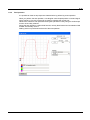
5.13 Drive Inrush Current ................................................................................................................... 5-27
5.13.1 Inrush Current Waveforms (representative examples)..................................................... 5-27
5.13.2 Selecting Circuit Breaker .................................................................................................. 5-27
5.13.3 Selecting Fuse .................................................................................................................. 5-28
6.
Operation ............................................................................................................................................... 6-1
6.1
Common Basic Functions............................................................................................................. 6-1
6.1.1
6.1.2
6.1.3
6.1.4
6.1.5
I/O Signals .......................................................................................................................... 6-1
I/O Registers..................................................................................................................... 6-15
#parameters/#monitors .................................................................................................... 6-17
Operation Privilege ........................................................................................................... 6-24
Process Settings in Error State ........................................................................................ 6-26
TI 71M02D04-01EN
10th Edition: 2012.12.01
TOC-3
6.1.6
6.1.7
6.1.8
6.1.9
6.2
Methods of Issuing Servo-ON Commands ....................................................................... 6-30
Signal Timing when Turning the Power ON ..................................................................... 6-31
Coordinate Systems ......................................................................................................... 6-33
Velocity Profile .................................................................................................................. 6-36
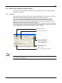
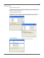
Initial Operation Test .................................................................................................................. 6-42
6.2.1
Initial Operation Test Using the Utility Software ............................................................... 6-42
6.3
Jog Move .................................................................................................................................... 6-50
6.4
Table Data Operation ................................................................................................................. 6-54
6.4.1
6.4.2
6.4.3
6.4.4
6.4.5
6.4.6
6.4.7
6.4.8
6.4.9
6.4.10
6.4.11
6.4.12
Table Data Operation........................................................................................................ 6-54
Setting Operation Register ............................................................................................... 6-62
Auto-tuning Operation ...................................................................................................... 6-67
Test Operation .................................................................................................................. 6-71
Homing ............................................................................................................................. 6-74
ABS (Absolute) Positioning Move .................................................................................... 6-86
INC (Incremental) Positioning Move................................................................................. 6-89
Dwell ................................................................................................................................. 6-92
Parameter Change ........................................................................................................... 6-93
Conditional Branch ........................................................................................................... 6-97
Command ......................................................................................................................... 6-99
Startup Operation ........................................................................................................... 6-102
6.5
Control Using the PLC .............................................................................................................. 6-103
6.6
Position Settling Signal ............................................................................................................. 6-104
6.7
Signal Monitor Function ............................................................................................................ 6-107
6.8
Area Signal ............................................................................................................................... 6-110
6.9
Torque/thrust Control Function ................................................................................................. 6-111
6.10 Special Functions of CC-Link ................................................................................................... 6-112
6.10.1 6.10.1 .............................................................................................................................. 6-115
7.
Tuning .................................................................................................................................................... 7-1
7.1
How to Tune the Servo ................................................................................................................. 7-1
7.2
Resonance Prevention ................................................................................................................. 7-3
7.2.1
7.2.2
7.2.3
8.
Prevention of Mechanical Resonance ................................................................................ 7-3
Filters .................................................................................................................................. 7-4
If the Motor Oscillates during Auto-tuning ........................................................................ 7-10
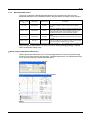
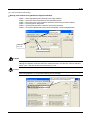
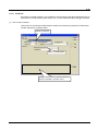
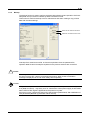
Utility Software ...................................................................................................................................... 8-1
8.1
Introduction ................................................................................................................................... 8-1
8.1.1
8.1.2
8.1.3
8.2
Overview ....................................................................................................................................... 8-4
8.2.1
8.2.2
8.3
Function Groups ................................................................................................................. 8-4
Function List ....................................................................................................................... 8-5
Required Settings Prior to Connecting ......................................................................................... 8-7
8.3.1
8.3.2
8.3.3
8.4
Operating Conditions .......................................................................................................... 8-1
Communication Cable ........................................................................................................ 8-2
Installing and Uninstalling ................................................................................................... 8-3
Connecting and Reconnecting ........................................................................................... 8-7
Communication Settings .................................................................................................... 8-7
Other Settings..................................................................................................................... 8-8
Details of the Operation Group Function ...................................................................................... 8-9
TI 71M02D04-01EN
10th Edition: 2012.12.01
TOC-4
8.4.1
8.4.2
8.5
Details of the Display Group Function ........................................................................................ 8-14
8.5.1
8.5.2
8.5.3
8.5.4
8.5.5
8.6
9.
#parameters ..................................................................................................................... 8-30
Table Data Function.......................................................................................................... 8-34
I/O ..................................................................................................................................... 8-35
Details of the Maintenance Group Function ............................................................................... 8-37
8.7.1
8.7.2
8.7.3
8.7.4
8.7.5
8.8
Oscilloscope ..................................................................................................................... 8-14
Displaying #parameter/ #monitor ..................................................................................... 8-26
I/O monitor ........................................................................................................................ 8-27
Axis Signal Monitor ........................................................................................................... 8-28
Error Monitor..................................................................................................................... 8-29
Details of the Data Management Group Function ...................................................................... 8-30
8.6.1
8.6.2
8.6.3
8.7
Operation ............................................................................................................................ 8-9
Terminal ............................................................................................................................ 8-10
#parameter Maintenance ................................................................................................. 8-37
Table Data Maintenance ................................................................................................... 8-38
I/O Maintenance ............................................................................................................... 8-39
Backup.............................................................................................................................. 8-40
Version Information .......................................................................................................... 8-41
FAQ Pertaining to the Utility Software ........................................................................................ 8-42
Maintenance and Inspection................................................................................................................ 9-1
9.1
Daily Inspection ............................................................................................................................ 9-1
9.2
Backup and Restore Operations of User Data ............................................................................. 9-2
9.3
Initialization of User Data (Reset All) ............................................................................................ 9-2
9.4
Lubrication of the Motor Unit ........................................................................................................ 9-3
Appendix 1 Parameter Description ......................................................................................... Appendix 1-1
Appendix 2 Monitor Description .............................................................................................. Appendix 2-1
Appendix 3 Detail of Main Error Codes .................................................................................. Appendix 3-1
Appendix 4 Glossary ................................................................................................................ Appendix 4-1
Appendix 5 Description of Iperation Tables and Sample Programs .................................... Appendix 5-1
Revision Record
TI 71M02D04-01EN
10th Edition: 2012.12.01
1-1
1. Overview of the Product
1.1
LM Series Motor
The LINEARSERV LM Series motors are direct-drive linear servo motors. They allow highly
accurate positioning control thanks to a fully closed loop configuration using Yokogawa's
proprietary built-in optical linear encoder.
Additionally, they offer smooth drive characteristics that are not possible with conventional
ball screws and AC servo motors.
5
LS (LS: length of stroke), yielding a high
1000
precision of 10 μm with a stroke length of 1000 mm
Repeated positioning accuracy: 0.1 to 0.5 μm (depending on the shape)
Velocity ripple: 1%.
The series offers an all-in-one type with integrated motor unit, encoder and linear guide
unit that is easy to incorporate with other machinery.
Unique positioning control configurations are possible with the multiple sliders.
Stable operation is achieved with minimal temperature increase.
A proven linear guide is employed for the mechanism, and sufficiently high rigidity is
ensured under load conditions.
The high-speed type allows operation at up to 2 m/sec.
Twenty types of strokes, ranging from 50 mm to 1800 mm, are available.
The line includes standard, high-rigidity, high-speed and high-rigidity/high-speed models
with motor thrust rating of 50 N, 100 N or 300 N, as well as a high-rigidity model with a
motor thrust rating of 400 N.
Wide-ranging applications are supported through various combinations of thrust, stroke
and shape.
Absolute positioning accuracy: 5 +
1.2
DrvPIII Drive
The DrvPIII is a direct drive servo motor drive designed exclusively for positioning operation,
offering improved control performance and operability.
The DrvPIII supports motors of absolute type as well as increment type. Additionally, two
types of controller interfaces--contact I/O and CC-Link--are provided.
TI 71M02D04-01E 10th Edition: 2012.12.01
1-2
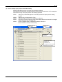
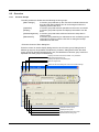
Checking the Product
Please check the product as soon as you receive it. Please examine the label and check that
the types and quantities of the parts and products received, as well as accessories you have
ordered, are correct. Perform a visual inspection to ensure that there are no abnormalities in
their appearance.
If you received a different product than you ordered or the product does not conform to your
expectations, please contact us or the dealer from whom you purchased the product
immediately.
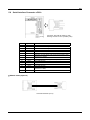
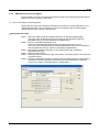
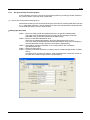
Motor unit
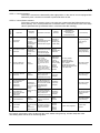
Name of product/accessory
Shape
Remarks
Motor unit
Paired with a motor
and tuned
Head amplifier
Drive
TB1 power supply terminal
connector
(231-204/026-000 WAGO)
The shape varies
depending on the model.
Standard accessories
(one piece per drive)
TB2 motor terminal connector
(231-203/026-000 WAGO)
TB3 regeneration terminal
connector
(231-202/026-000 WAGO)
Drive unit
1.3
Models provided
regenerative resistors
(one piece per drive)
See the table on the
next page
Screw-less terminal lever
(231-131 WAGO)
TB4 sensor terminal connector
(733-106 WAGO)
Standard accessories
(one piece per drive)
Regenerative resistor
Models provided
regenerative resistors
(one piece per drive)
See the table on the
next page
CN2 encoder/resolver connector
(PCR-S20F, PCR-LS20LA1
Honda Tsushin Kogyo)
Supplied when order
includes the additional
suffix code "/CN."
CN4 controller interface connector
(PCR-S36FS, PCR-LS36LA
Honda Tsushin Kogyo)
Supplied when the order
includes contact I/O "XA"
and additional suffix code
"/CN."
CN4 controller interface connector
(TMSTBP 2, 5/4-ST-5, 08
Phoenix Contact)
Supplied when the order
includes CC-Link "C1"
and additional suffix code
"/CN."
Option cables
Optional
TI 71M02D04-01E 10th Edition: 2012.12.01
1-3
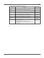
List of Models Provided with Regenerative resistors
A regenerative resistor is provided for the models listed in the table below.
Model
UM1LP3
Suffix code
-240-A-1-N
-330-A-1-N
-530-A-1-N
-240-A-2-N
-330-A-2-N
-530-A-2-N
Regenerative resistor
80W
60 Ω
80W
200 Ω
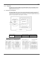
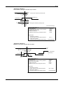
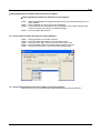
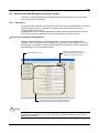
Faceplate of the Motor
1
Slider number
Motor model/suffix code
LM105-1N
-030AN-G2N-N2F
/CN
203MM12345A1
Made in Japan
Displayed on
the side panel
Serial number
Label
Head amplifier
Faceplate of the Drive
Drive model/suffix code, style No.
Input
Output
DD SERVO ACTUATOR
UM1LP3
S1.01
-105C-1AA -2SA-N
C
203MM12345A1
Made in Japan K
Serial number
Label
TI 71M02D04-01E 10th Edition: 2012.12.01
Blank Page
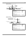
2-1
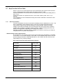
2. Specifications
2.1
Standard Specifications
Standard Model
Item
Positioning
LM105
LM110
LM130
N
50
100
300
25
50
150
Rated thrust *2
N
Maximum velocity
m/s
1.0
Rated velocity *3
m/s
0.83(0.16)
Encoder resolution *3
μm
0.25 (0.05)
Repeated positioning accuracy *3
μm
±0.5 (±0.1)
Absolute positioning accuracy by
length of stroke [LS] *1
Maximum power consumption
(100V/200V)
Rated power consumption
(100V/200V) *2
Motor
Motor and drive
Maximum thrust
Unit
5
Ls
1000
VA
300/600
350/700
400/800
VA
170/170
212/212
315/475
Maximum load
N
Slider weight
kg
Rail weight
kg/m
Length of stroke [LS]
5+
μm
mm
200
1000
1.0
1.4
5.0
12
15
25
50/100/150/200/300/400/500/600/700/800/900
1000/1100/1200/1300/1400/1500/1600/1700/1800
*1. Scale accuracy specification at 23°C (expansion coefficient of glass lines: 8 x 10⁻⁶/°C)
*2. Indicates CE continuous rating
*3. Values in ( ) indicate a resolution specification of 0.05 μm.
High-rigidity Model
Positioning
Motor and drive
Item
LM250
LM210
LM240
LM130
Maximum thrust
N
50
100
300
400
Rated thrust *2
N
25
50
150
200
Maximum velocity
m/s
1.0
Rated velocity *3
m/s
0.83 (0.16)
μm
0.25 (0.05)
μm
±0.5 (±0.1)
Encoder resolution *3
Repeated positioning accuracy
*3
Absolute positioning accuracy
by length of stroke [LS] *1
Maximum power consumption
(100V/200V)
Rated power consumption
(100V/200V) *2
Maximum load
Motor
Unit
5+
μm
5
Ls
1000
VA
300/600
350/700
400/800
550/1100
VA
170/170
212/212
315/475
315/475
N
600
2000
Slider weight
kg
1.4
1.8
8.7
10.0
Rail weight
kg/m
15
18
45
50
Length of stroke [LS]
mm
50/100/150/200/300/400/500/600/700/800/900
1000/1100/1200/1300/1400/1500/1600/1700/1800
*1. Scale accuracy specification at 23°C (expansion coefficient of glass lines: 8 x 10⁻⁶/°C)
*2. Indicates CE continuous rating
*3. Values in ( ) indicate a resolution specification of 0.05 μm.
TI 71M02D04-01EN 10th Edition: 2012.12.01
2-2
High-speed Model
Positioning
Unit
LM505
LM510
LM530
Maximum thrust
N
40
90
270
Rated thrust *2
N
20
45
135
Maximum velocity
m/s
2.5
Rated velocity
m/s
2.0
Encoder resolution
μm
0.5
Repeated positioning accuracy
μm
±1
Absolute positioning accuracy by
length of stroke [LS] *1
Maximum power consumption
(100V/200V)
Rated power consumption
(100V/200V) *2
Motor
Motor and drive
Item
5+
μm
5
Ls
1000
VA
300/600
350/700
550/1100
VA
250/250
315/355
315/630
Maximum load
N
Slider weight
kg
Rail weight
kg/m
Length of stroke [LS]
mm
200
1000
1.0
1.4
5.0
12
15
25
50/100/150/200/300/400/500/600/700/800/900
1000/1100/1200/1300/1400/1500/1600/1700/1800
*1. Scale accuracy specification at 23°C (expansion coefficient of glass lines: 8 x 10⁻⁶/°C)
*2. Indicates CE continuous rating
High-rigidity/High-speed model
Item
Motor
Positioning
Motor and drive
Maximum thrust
Unit
LM305
LM310
LM330
N
40
90
270
20
45
135
Rated thrust *2
N
Maximum velocity
m/s
Rated velocity
2.5
m/s
2.0
Encoder resolution
μm
0.5
Repeated positioning accuracy
μm
±1
Absolute positioning accuracy
by length of stroke [LS] *1
Maximum power consumption
(100V/200V)
Rated power consumption
(100V/200V) *2
5+
μm
VA
300/600
VA
250/250
Maximum load
N
Slider weight
kg
Rail weight
kg/m
Length of stroke [LS]
mm
5
Ls
1000
350/700
550/1100
315/355
315/630
600
2000
1.4
1.8
8.7
15
18
45
50/100/150/200/300/400/500/600/700/800/900
1000/1100/1200/1300/1400/1500/1600/1700/1800
*1. Scale accuracy specification at 23°C (expansion coefficient of glass lines: 8 x 10⁻⁶/°C)
*2. Indicates CE continuous rating
TI 71M02D04-01EN 10th Edition: 2012.12.01
2-3
Motor Environment Specifications
Motor
Operation
Storage
Temperature
0 ~ 45°C: Standard
0 ~ 40°C: CE
continuous rating
Humidity
20 ~ 85% RH
Temperature
-20 ~ 85°C
Humidity
20 ~ 85% RH
Atmosphere
Remarks
No condensation
No condensation
Must be no corrosive gasses, dust and dirt
Must be used at a maximum altitude of 1000
meters above sea level (CE mounting condition)
TI 71M02D04-01EN 10th Edition: 2012.12.01
2-4
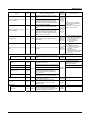
Drive General Specifications and Function Specifications
Basic Specification
Constructio
Environment
n
Power supply
500W class
+10%
100 ~ 115VAC / 200 ~ 230VAC
Main power supply
-15%
50/60 Hz
Maximum power consumption 1.3kVA
+10%
100 ~ 115VAC / 200 ~ 230VAC
Control power supply
-15%
50/60 Hz
Maximum power consumption 40VA
Temperature
0 ~ +50°C (Operation) / 20 ~ +85°C (Storage)
Humidity
Atmosphere
20 ~ 90%RH, No condensing (Operation and Storage)
No corrosive gases, dust-free atmosphere
Must be used at a maximum altitude of 1000 meters above sea level (CE mounting condition)
Installation
Wall-mount
Fan
N/A
Regenerative resistor
External
External Dimension
60 W x 195 H x 150 D (mm)
Weight
Conformed standard
HiPot
1.2kg
Low voltage (declaration) EN50178, EMC (declaration) EN55011 class A group 1, EN61800-3
UL508C
Insulating resistance: 10MΩ or more (500VDC), Withstand voltage 1500VAC, one minute
Encoder Resolution
LINEARSERV
Values inside ( ) is factory
default value for command
and monitor pulses
Host interface
Serial Interface
(RS232C/RS485)
Controller Interface
Control part
Mechanical Input Signal
UM1LP3-B: 0.5μm (1.0μm)
UM1LP3-C: 0.25μm (1.0μm)
UM1LP3-E: 0.05μm (1.0μm)
Communication
Start-stop system, binary communication
Communication Speed
38,400 bps
Multi-channel (RS485)
Max. 10 channels
Contact I/O (XA for interface type and specification)
No. of input points: 12 points, No. of output points: 6 points (with a terminal assignment function)
CC-Link (C1 for interface type and specification)
When one occupied station is set up
No. of input points: 16 points, No. of output points: 16 points (with a terminal assignment
function)
Input registers: 4, output registers: 4
When two occupied stations are set up
No. of input points: 48 points, No. of output points: 48 points (with a terminal assignment
function)
Input registers: 8, output registers: 8
Home sensor, End Of Travel (EOT) sensor
Pos. control
I-PD control, PID control
Vel. control
Proportional control, proportional integral control
Feed Forward
Position, velocity, acceleration
Filter
Velocity command, velocity feedback, phase delay compensation and notch (2ch) filters
Operation Functions
Homing, test, auto-tuning, positioning and jog move functions
Protection Functions
Encoder error, over voltage, over current, low bus line power voltage, power failure, over load, regen.
Error detection, over speed, excessive pos. deviation, hardware EOT and software EOT (for linear
coordinate)
Monitor
Velocity, current instruction, analog (2ch) and digital (2ch)
Operation / Display
Operation display panel (optional)
Operation display pendant (optional)
Utility software
Miscellaneous
Servo deceleration function at power failure (immediate stop)
Dynamic brake (Select -1B or -1L for the model & suffix code.)
TI 71M02D04-01EN 10th Edition: 2012.12.01
2-5
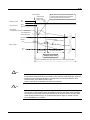
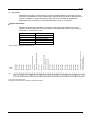
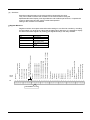
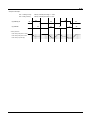
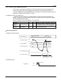
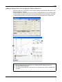
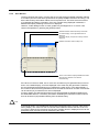
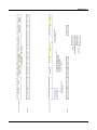
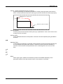
2.2
Thrust/Velocity Characteristics
Thrust (N)
LM Motor
200 V power supply
100 V power supply
Slider velocity (m/s)
TI 71M02D04-01EN 10th Edition: 2012.12.01
2-6
2.3
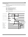
Model and Suffix Codes
Motor
Suffix Code
Model
LM105 - 2
N -050
Suffix Code (Optional)
A N -G 2 N -N 2 F / CE / CN / Z
Motor model
Special specification
LM105, LM110, LM130
LM205, LM210, LM230, LM240
LM305, LM310, LM330
LM505, LM510, LM530
Suffix code (optional)
CE: Conforming to CE mark/CN: Connectors attached/others
Main body connector material
Number of sliders
F: 172159-1/172162-1/170363-3 made by AMP /
M: RM21TR-15P made by Hirose
-1:1 slider/-2:2 slider
-3:3 slider/-4:4 slider
Clamp
Direction of main body connector
Always N (no clamp)
2: Right only (All connectors are pulled out to the right in the case of multiple sliders, as well.)
4: Left only (All connectors are pulled out to the left in the case of multiple sliders, as well.)
6: Right/left (can be selected in the case of two sliders only)
8: Left/right (can be selected in the case of two sliders only)
Length of stroke
Three-digit display in units of 1 cm, minimum -005 (5 cm), maximum -180 (180 cm)
Sensor installation position
Drive current
-N: No sensor
-P: Inside (Omron EE-SX670 or equivalent)
-R: Outside (Omron EE-SX670A or equivalent)
-S: Inside (Omron EE-SX670 or equivalent)
-T: Outside (Omron EE-SX670A or equivalent)
A:5A
Base structure
Always N
Scale material
Surface treatment
Always -G
N: Standard treatment
B: Mounting plate: Raydent treatment/Aluminum unit: Black alumite treatment
L: Mounting plate: Raydent treatment
Guide specification
Always 2
Model and Suffix Code Selection List
-4
-030, -040, -050,
-060, -070, -080,
-090, -100, -110,
-120, -130, -140,
-150, -160, -170,
-180
-040, -050, -060,
-070, -080, -090,
-100, -110, -120,
-130, -140, -150,
-160, -170, -180
N
G
2
N,
B,
L
-P,
-S
F
2,
4,
6,
8
F,
M
F
F,
M
-P,
-S
-P,
-S
Suffix code
2,
4
-N,
-R,
-T
-N,
-R,
-T
Main body
connector
material
Direction of main
body connector
Sensor
installation
position
Surface
treatment
Guide
specification
Scale material
Base structure
Drive current
-N,
-R,
-T
A
N
F,
M
-P,
-S
-015, -020, -030,
-040, -050, -060,
-070, -080, -090,
-100, -110, -120,
-130, -140, -150,
-160, -170, -180
-2
-3
-N,
-R,
-T
-005, -010, -015,
-020, -030, -040,
-050, -060, -070,
-080, -090, -100,
-110, -120, -130,
-140, -150, -160,
-170, -180
-1
LM105
LM110
LM505
LM510
Length of stroke
Clamp
Number of
sliders
Model
Suffix Code
/CE,
/CN,
/TC1
F
2,
4
F,
M
F
TI 71M02D04-01EN 10th Edition: 2012.12.01
2-7
-1
-2
LM130
LM530
N
-N,
-R,
-T
-020, -030, -040, 050, -060, -070, 080, -090, -100, 110, -120, -130, 140, -150, -160, 170, -180
-N,
-R,
-T
A
N
G
2
N,
B,
L
-P,
-S
-N,
-R,
-T
Suffix code
(optional)
F,
M
F
2,
4,
6,
8
-N,
-R,
-T
-P,
-S
Main body
connector
material
Direction of main
body connector
2,
4
-P,
-S
-060, -070, -080, 090, -100, -110, 120, -130, -140, 150, -160, -170, 180
-4
Sensor
installation
position
-005, -010, -015,
-020, -030, -040,
-050, -060, -070,
-080, -090, -100,
-110, -120, -130,
-140, -150, -160,
-170, -180
-040, -050, -060, 070, -080, -090, 100, -110, -120, 130, -140, -150, 160, -170, -180
-3
Surface
treatment
Guide
specification
Scale material
Base structure
Drive current
Length of stroke
Clamp
Number of
sliders
Model
Suffix Code
F,
M
F
F,
M
2,
4
/CE,
/CN,
/TC1
F
F,
M
-P,
-S
F
-1
-2
LM205
LM210
LM305
LM310
N
-3
-4
-005, -010, -015,
-020, -030, -040,
-050, -060, -070,
-080, -090, -100,
-110, -120, -130,
-140, -150, -160,
-170, -180
-N,
-R,
-T
-015, -020, -030,
-040, -050, -060,
-070, -080, -090,
-100, -110, -120,
-130, -140, -150,
-160, -170, -180
-N,
-R,
-T
-030, -040, -050,
-060, -070, -080,
-090, -100, -110,
-120, -130, -140,
-150, -160, -170,
-180
-050, -060, -070, 080, -090, -100, 110, -120, -130, 140, -150, -160, 170, -180
N
G
2
N,
B,
L
-P,
-S
2,
4
F
2,
4,
6,
8
-N,
-R,
-T
-P,
-S
-N,
-R,
-T
-P,
-S
Suffix code
(optional)
F,
M
-P,
-S
A
Main body
connector
material
Direction of main
body connector
Sensor
installation
position
Surface
treatment
Guide
specification
Scale material
Base structure
Drive current
Length of stroke
Clamp
Number of
sliders
Model
Suffix Code
F,
M
F
/CE,
/CN,
/TC1
F,
M
F
2,
4
F,
M
F
TI 71M02D04-01EN 10th Edition: 2012.12.01
2-8
2,
4
-2
-030, -040, -050, 060, -070, -080, 090, -100, -110, 120, -130, -140, 150, -160, -170, 180
2,
4,
6,
8
LM230
LM240
LM330
N
-3
-060, -070, -080,
-090, -100, -110,
-120, -130, -140,
-150, -160, -170,
-180
A
N
G
2
N,
B,
L
-N,
-P,
-R,
-S,
-T
Suffix code
(optional)
-1
-005, -010, -015,
-020, -030, -040,
-050, -060, -070,
-080, -090, -100,
-110, -120, -130,
-140, -150, -160,
-170, -180
Main body
connector
material
Direction of main
body connector
Sensor
installation
position
Surface
treatment
Guide
specification
Scale material
Base structure
Drive current
Length of stroke
Clamp
Number of
sliders
Model
Suffix Code
F,
M
/CE,
/CN,
/TC1
2,
4
-4
-080, -090, -100, 110, -120, -130, 140, -150, -160, 170, -180
TI 71M02D04-01EN 10th Edition: 2012.12.01
2-9
Drive
Model
Suffix code
Suffix code (optional)
UM1LP3 –105C -1A A -2 XA -N /CN
Drive model
UM1LP3
Suffix code (optional)
/CN: A set of connectors attache
Combined motor rating
See Model and Suffix Code list "-105" in the case of standard
model motor/position servo force of 50 N
Supported standard
Resolution
-N: Standard specification
B: 0.5μm / C: 0.25μm / E: 0.05μm
Basic structure
Interface type & specification
-A: 500 W without brake, -1B: 500 W built-in brake
XA: Contact I/O (12 for input, 6 for output, 12 to 24 V)
C1: CC-Link
Drive current
A: 5A
Power supply voltage
-1: 100 VAC system, -2: 200 VAC system
Model and Suffix Code Selection List
500W-class drive
Drive current
Power supply
voltage
I/F type &
specification
Supported
standard
-1A,
-1B
A
-1,
-2
XA,
C1,
-N
Suffix code
(optional)
Basic structure
UM1LP3
-105
-110
-130
-205
-210
-230
-240
-305
-310
-330
-505
-510
-530
Resolution
Model
Combined
motor rating
Suffix code
C,
E
/CN
B
TI 71M02D04-01EN 10th Edition: 2012.12.01
2-10
2.4
2.4.1
Option Cables
Option Cable Model and Suffix Code
Encoder/Resolver Cable
Suffix code
Model
C1E –E A 1 –79 62 -030
Encoder/resolver cable model
Cable length
3-digit display in units of 10 cm, minimum -005 (50 cm), maximum -300 (30 m)
See the model and suffix code selection list.
Drive type
-B: UB5P3
-E: UDP3
-M: UM1LP3
-S: URP3
Termination option (Motor side)
01: No lead
02: Open leads (core wire revealed)
06: With MS3106B18-1S and MS3057-10A made by JAE
62: With 172170-1 and 170365-3 made by AMP (Japan)
79: With PCR-S20FS and PCR-LS20LA1 made by Honda Tsushin Kogyo
80: With NJC-2012-PF made by Nanaboshi Electric Mfg
90: With RM21TP-15S (HRS No. 109-0321) made by Hirose
Drive current
A: 5A, 6A
C: 15A, 20A
Cable type
1: Robot cable
2: Fixed cable
Termination option (Drive side)
-01: No lead
-02: Open leads (core wire revealed)
-08: With MS3101B18-4P made by JAE (for relay)
-22: With DA-15PF-N and DA-C8-J10-F4-1 made by JAE
-69: With 172162-1 and 170363-3 made by AMP (Japan) (for relay)
-73: With NJC-2012-AdM made by Nanaboshi Electric Mfg (for relay)
-79: With PCR-S20FS and PCR-LS20LA1 made by Honda Tsushin Kogyo
-91: With DA-15PF-N and DA-C8-J01-F4-1 made by JAE and round terminal (J.S.T. Mfg N1.25-M4)
-92: With 172162-1, 172159-1 and 170363-3 made by AMP (Japan)
-93: With DA-15PF-N and DA-C8-J10-F4-1 made by JAE,
GND cable, N1.25-M4 made by J.S.T. Mfg
Model and Suffix Code Selection List
Suffix code
Drive type
Drive
current
Cable
type
Termination
option (Drive
side)
Termination
option (Motor
side)
-01, -02, -79
01, 02, 69, 79
-08, -69, -73
06, 62, 80
-22
62
-91, -92, -93
90
-01, -02, -79
01, 02, 79, 80
-08, -69, -73
06, 62, 80
-22
62
Cable length
-005, -010, -015, -020
-025, -030, -035, -040,
-045, -050, -060, -070,
-080, -090, -100
Description
Relay cable
1
Model
-M
A
2
-005, -010, -015, -020
-025, -030, -035, -040,
-045, -050
-005, -010, -015, -020
-025, -030, -035, -040,
-045, -050, -060, -070,
-080, -090, -100
-005, -010, -015, -020
-025, -030, -035, -040,
-045, -050
Head amplifier cable
Relay cable
Head amplifier cable
TI 71M02D04-01EN 10th Edition: 2012.12.01
2-11
Motor Cable
Suffix code
Model
C1M –N A 1 –60
61 –030
Cable length
Motor cable model
3-digit display in units of 10 cm, minimum -005 (50 cm), maximum -300 (30 m)
See the model and suffix code selection list.
Drive type
Always -N
Termination option (Motor side)
Drive current
01: No lead
02: Open leads (core wire revealed)
06: With MS3106B20-4S and MS3057-12A made by JAE
61: With 172167-1 and 170366-3 made by AMP (Japan)
70: With 3191-06R and 1189ATL made by Molex
74: With NCS-304-P made by Nanaboshi Electric Mfg
A: 5A, 6A
C: 15A, 20A
Cable type
1: Robot cable
2: Fixed cable
Termination option (Drive side)
-01: No lead
-02: Open leads (core wire revealed)
-03: With N2-4 made by J.S.T. Mfg
-08: With MS3106B20-4P made by JAE (for relay)
-20: With GND cable, N1.25-M4 or N2-4 made by J.S.T. Mfg
-60: With N1.25-M4 made by J.S.T. Mfg
-68: With 172159-1 and 170364-3 made by AMP (Japan) (for relay)
-71: With 3191-06P and 1190TL made by Molex (for relay)
-72: With NCS-304-Ad made by Nanaboshi Electric Mfg (for relay)
Model and Suffix Code Selection List
-01, -02, -20, -60
A
01, 02, 61, 74
-68, -72
C1N
-N
1, 2
-01, -02, -03, -20
C
-08, -71, -72
01, 02, 06,
70, 74
Cable length
Termination
option
(Motor side)
Termination
option (Drive
side)
Cable type
Drive current
Model
Drive type
Suffix code
-005, -010, -015, -020,
-025, -030, -035, -040,
-045, -050, -060, -070,
-080, -090, -100
-005, -010, -015, -020,
-025, -030, -035, -040,
-045, -050, -060, -070,
-080, -090, -100, -150,
-200, -250, -300
Description
Relay cable
Relay cable
TI 71M02D04-01EN 10th Edition: 2012.12.01
2-12
Controller Cable
Model
Suffix code
C 1 P – E N N – 2 2 76 – 0 2 0
Controller cable model
Cable length
Drive type
3-digit display in units of 10 cm, minimum -002 (20 cm), maximum -050 (5 m)
See the model name specification code selection table
-E: UDG3
-M: UM1LG3
-S: URG3
Termination option (Controller side)
02: Open leads (core wire revealed)
76: With DE-9SF-N and DE-C8-J9-F4-1 made by JAE (RS-232C for DOS)
Drive current
Always N
Termination option (Drive side)
Cable type
Always N
-22: With DA-15PF-N and DA-C8-J10-F4-1 made by JAE
-42: With PCR-S36FS and PCR-LS36LA made by Honda Tsushin Kogyo
Model and Suffix Code Selection List
C1P
-E
N
Termination
option
(Controller
side)
-22
76
N
-42
02
Cable length
Termination
option (Drive
side)
Cable type
Drive current
Model
Drive type
Suffix code
-020
-002, -003, -004, -005,
-006, -007, -008, -009,
-010, -012, -015, -020,
-022, -025, -030, -035,
-040, -045, -050
Description
RS-232C cable for CN1
(for DOS)
PLC cable for CN4
TI 71M02D04-01EN 10th Edition: 2012.12.01
2-13
2.4.2
Recommended Cables
Recommended Cables for LM Motors
Cable
Model and Suffix code
C1M-NA1-2061-
Amplifier
cable
J.S.T. Mfg
N1.25-M4
Made by JAE
Connector DA-15PF-N
Contact DA-C8-J10-F4-1
Encoder
cable
Motor cable
Connector, drive side
Made by Honda Tsushin
Kogyo
Connector PCR -S20FS
Cover PCR-LS20LA1
C1E-MA1-2262-
C1E-MA-7979-
Connector, motor side
Made by AMP (Japan)
Connector 172167-1
Contact 170366-3
Made by AMP (Japan)
Connector 172170-1
Contact 170365-3
Made by Honda Tsushin
Kogyo
Connector PCR -S20FS
Cover PCR-LS20LA1
Motor, Head amplifier
Made by AMP (Japan)
Connector 172159-1
Contact 170364-3
Made by AMP (Japan)
Connector 172162-1
Contact 170363-3
Made by Honda Tsushin
Kogyo
Connector PCR -S20FS
Cover PCR-LS20LA1
TI 71M02D04-01EN 10th Edition: 2012.12.01
2-14
2.4.3
Cable Specifications
Motor Cable (Robot cable)
Identification of core wire
Sheath
Layout number
1
2
3
4
Shield
Color of insulating
material
Black
White
Red
Green
Insulating material
Conductor
Cable specifications
2
Conductor
AWG#20 (0.5mm )
Insulating material external diameter
∅1.64mm
Finished external diameter
∅7.0mm
Amplifier Cable (Robot cable)
Identification of core wire
Sheath
Shield
Layout
number
1
2
3
Color of
insulating Green Yellow Brown
material
4
5
6
7
Blue Orange Gray
8
Purple Black
9
10
White
Red
Insulating material
Conductor
Cable specifications
2
Conductor
AWG#22 (0.3mm )
Insulating material external diameter
∅1.29mm
Finished external diameter
∅8.5mm
Encoder Cable
(1) Fixed cable
Sheath
Shield
Insulating material
Conductor
Identification of core wire
Layout number
1
Blue x
blue/
white
Color of
insulating
material
2
3
4
Brown x
brown
/white
Red x
Black
Orange x
orange/
white
Cable specifications
2
Conductor
AWG#24 (0.2mm )
Insulating material external
diameter
∅1.05mm (Twisted pair)
Finished external diameter
∅6.8mm
(2) Robot cable
Identification of core wire
Sheath
Shield
Insulating material
Conductor
Layout
number
1
2
3
Color of
insulating Green Yellow Brown
material
4
5
6
Blue Orange Gray
7
8
Purple Black
9
10
White
Red
Cable specifications
2
Conductor
AWG#22 (0.3mm )
Insulating material external diameter
∅1.29mm
Finished external diameter
∅8.5mm
TI 71M02D04-01EN 10th Edition: 2012.12.01
2-15
2.5
Outline Drawings
2.5.1
Motor
LM105/LM110/LM505/LM510 (Dimensions in [ ] indicate LM105/LM505)
Unit in figure: mm
Length of stroke100 mm
Length of stroke 50 mm
(Slider width)
4-M3, depth 3.5
Wiring connector
Made by AMP, 4-pole, 12-pole
130 (Total slider length)
4-M3, depth 3.5
(Stroke)
Wiring connector
Made by AMP, 4-pole, 12-pole
Stopper
3-M3, depth 5
(For cable attachment)
∅4.5 hole, ∅8 spot facing depth 8.5
Mounting hole for fixed unit
220 (Total motor length)
130 (Total slider length)
100 (Stroke)
Stopper
3-M3, depth 5
(For cable attachment)
∅4.5 hole, ∅8 spot facing depth 8.5
Mounting hole for fixed unit
4-M4, depth 10
From edge
surface of
moving part
From edge
surface of
moving part
4-M4, depth 10
(Slider width)
4-M6, depth 10
Moving part mounting tap
4-M6, depth 10
Moving part mounting tap
270 (Total motor length)
Length of stroke 150 to 1800 mm
4-M6, depth 10
Moving part mounting tap
Encoder unit
4-M3, depth 3.5
(Slider width)
Wiring connector
Made by AMP, 4-pole, 12-pole
Ls (Stroke)
(Two pieces on
the opposite side)
130 . (Total slider length)
∅4.5 hole, ∅8 spot facing depth 8.5
Mounting hole for fixed unit
From edge
surface of fixed unit
From edge
surface of
moving part
4-M4, depth 10
Stopper
3-M3, depth 5
(For cable attachment)
Model
L (Total motor length = Ls + 170mm)
LM105
LM110
LM505
LM510
-1N-015
-1N-020
-1N-030
-1N-040
-1N-050
-1N-060
-1N-070
-1N-080
-1N-090
-1N-100
-1N-110
-1N-120
-1N-130
-1N-140
-1N-150
-1N-160
-1N-170
-1N-180
L
Ls
N
320
370
470
570
670
770
870
970
1070
1170
1270
1370
1470
1570
1670
1770
1870
1970
150
200
300
400
500
600
700
800
900
1000
1100
1200
1300
1400
1500
1600
1700
1800
5
6
8
10
12
14
16
18
20
22
24
26
28
30
32
34
36
38
Mounting
hole for fixed
unit
2 x 6 pieces
2 x 7 pieces
2 x 9 pieces
2 x 11 pieces
2 x 13 pieces
2 x 15 pieces
2 x 17 pieces
2 x 19 pieces
2 x 21 pieces
2 x 23 pieces
2 x 25 pieces
2 x 27 pieces
2 x 29 pieces
2 x 31 pieces
2 x 33 pieces
2 x 35 pieces
2 x 37 pieces
2 x 39 pieces
TI 71M02D04-01EN 10th Edition: 2012.12.01
2-16
LM205/LM210/LM305/LM310 (Dimensions in [ ] indicate LM205/LM305)
Length of stroke 50 mm
Length of stroke100 mm
4-M3, depth 3.5
Wiring connector
Made by AMP, 4-pole, 12-pole
(Stroke)
140 . (Total slider length)
4-M3, depth 3.5
Stoppe
3-M3, depth 5
(For cable attachment)
∅4.5 hole, ∅8 spot facing depth 10
Mounting hole for fixed unit
4-M4, depth 10
From edge
surface of
moving part
From edge
surface of
moving part
4-M4, depth 10
(Slider width)
4-M6, depth 10
Moving part mounting tap
(Slider width)
4-M6, depth 10
Moving part mounting tap
Wiring connector
Made by AMP, 4-pole, 12-pole
(Total slider length)
(Stroke)
230 (Total motor length)
Stopper
3-M3, depth 5
(For cable attachment)
∅4.5 hole, ∅8 spot facing depth 10
Mounting hole for fixed unit
(Total motor length)
Length of stroke150 to 1800 mm
4-M6, depth 10
Moving part mounting tap
From edge
surface of
moving part
4-M4, depth 10
Wiring connector
Made by AMP, 4-pole, 12-pole
Ls (Stroke)
4-M3, depth 3.5
(Total slider length)
(Two pieces
on the opposite side)
From edge
surface of
fixed unit
(Slider width)
Encoder unit
∅4.5 hole, ∅8 spot facing depth
Mounting hole for fixed unit
3-M3, depth 5
(For cable attachment)
Stopper
Model
L (Total motor length = Ls + 170mm)
LM205
LM210
LM305
LM310
-1N-015
-1N-020
-1N-030
-1N-040
-1N-050
-1N-060
-1N-070
-1N-080
-1N-090
-1N-100
-1N-110
-1N-120
-1N-130
-1N-140
-1N-150
-1N-160
-1N-170
-1N-180
L
Ls
N
330
380
480
580
680
780
880
980
1080
1180
1280
1380
1480
1580
1680
1780
1880
1980
150
200
300
400
500
600
700
800
900
1000
1100
1200
1300
1400
1500
1600
1700
1800
5
6
8
10
12
14
16
18
20
22
24
26
28
30
32
34
36
38
Mounting
hole for fixed
unit
2 x 6 pieces
2 x 7 pieces
2 x 9 pieces
2 x 11 pieces
2 x 13 pieces
2 x 15 pieces
2 x 17 pieces
2 x 19 pieces
2 x 21 pieces
2 x 23 pieces
2 x 25 pieces
2 x 27 pieces
2 x 29 pieces
2 x 31 pieces
2 x 33 pieces
2 x 35 pieces
2 x 37 pieces
2 x 39 pieces
TI 71M02D04-01EN 10th Edition: 2012.12.01
2-17
LM130/LM530
Length of stroke 50 mm
Length of stroke 100 mm
4-M8, depth 10
Moving part mounting tap
4-M8, depth 10
Moving part mounting tap
4-M4, depth 10
Wiring connector
Made by AMP, 4-pole, 12-pole
(Total slider length)
*5-M3, depth 5
(Stroke)
4-M3, depth 3.5
(Slider width)
From edge
surface of
moving part
From edge
surface of
moving part
(Slider width)
4-M4, depth 10
Wiring connector
Made by AMP, 4-pole, 12-pole
(Stroke)
4-M3, depth3.5
(For cable attachment)
Stopper
∅7 hole, ∅11 spot facing depth 9
4-Mounting hole for fixed unit
(Total slider length)
*5-M3, depth 5
(For cable attachment)
Stopper
∅7 hole, ∅11 spot facing depth 9
4-Mounting hole for fixed unit
(Total motor length)
(Total motor length)
Length of stroke 150 mm
Sensor mounting position diagram
(common to all models)
(1) Outside sensors
4-M8, depth 10
Moving part mounting tap
(2) Inside sensors
From edge
surface of
moving part
(Slider width)
4-M4, depth 10
Wiring connector
Made by AMP, 4-pole, 12-pole
(Stroke)
4-M3, depth 3.5
∅7 hole, ∅11 spot facing depth 9
8-Mounting hole for fixed unit
(Sensor interval)
(Total slider length)
Photo-sensor
and connector
*5-M3, depth 5
(For cable attachment)
(EOT position: stroke toward outside)
(Home position stroke toward inside)
(EOT position: stroke toward outside)
Photo-sensor
and connector
(Home position: stroke toward inside)
(Sensor interval)
Stopper
(Total motor length)
Photo-sensor: EE-SX670A (Omron)
Connector:
EE-1001 (Omron)
Mounting 4 pieces, 2 for each side
TI 71M02D04-01EN 10th Edition: 2012.12.01
2-18
Length of stroke 150 to 1800mm
4-M8, depth 10
Moving part mounting tap
Encoder unit
Model
Wiring connector Made by AMP, 4-pole, 12-pole
(Total slider length)
(Stroke)
4-M3, depth 3.5
∅7 hole, ∅11 spot facing depth 9
Mounting hole for fixed unit
(Two pieces on
the opposite side)
*5-M3, depth 5
(For cable attachment)
From edge surface of fixed unit
From edge
surface of
moving part
Slider width)
4-M4, depth 10
LM130
LM530
Stopper
L (Total motor length)
-1N-020
-1N-030
-1N-040
-1N-050
-1N-060
-1N-070
-1N-080
-1N-090
-1N-100
-1N-110
-1N-120
-1N-130
-1N-140
-1N-150
-1N-160
-1N-170
-1N-180
L
Ls
N
430
530
630
730
830
930
1030
1130
1230
1330
1430
1530
1630
1730
1830
1930
2030
200
300
400
500
600
700
800
900
1000
1100
1200
1300
1400
1500
1600
1700
1800
3
4
5
6
7
8
9
10
11
12
13
14
15
16
17
18
19
Mounting
hole for fixed
unit
2 x 4 pieces
2 x 5 pieces
2 x 6 pieces
2 x 7 pieces
2 x 8 pieces
2 x 9 pieces
2 x 10 pieces
2 x 11 pieces
2 x 12 pieces
2 x 13 pieces
2 x 14 pieces
2 x 15 pieces
2 x 16 pieces
2 x 17 pieces
2 x 18 pieces
2 x 19 pieces
2 x 20 pieces
LM230/LM240/LM330 (Dimensions in [ ] indicate LM240)
Length of stroke 50mm
Encoder unit
4-M8, depth 10
Moving part mounting tap
Wiring connector Made by AMP, 4-pole, 12-pole
250 (Total slider length)
(Stroke)
∅7 hole, ∅11 spot facing depth 11
Mounting hole for fixed unit
From edge surface of fixed unit
From edge
surface of
moving part
4-M4, depth 10
4-M3
(Two pieces on the
opposite side)
*5-M3, depth 5
(For cable attachment)
4-M3, depth 3.5
Model
340 (Total motor length)
LM230
LM240
LM330
-1N-005
L
Ls
Mounting hole
for fixed unit
340
50
2 x 2 pieces
TI 71M02D04-01EN 10th Edition: 2012.12.01
2-19
Length of stroke 100 to 200mm
Encoder unit
4-M8, depth 10
Moving part mounting tap
Wiring connector Made by AMP, 4-pole, 12-pole
250 (Total slider length)
Ls (Stroke)
∅7 hole, ∅11 spot facing depth 11
Mounting hole for fixed unit
From edge
surface of
fixed unit
From edge surface
of moving part
4-M4, depth 10
4-M3
(Two pieces on the
opposite side)
*5-M3, depth 5
(For cable attachment)
4-M3, depth 3.5
Model
LM230
LM240
LM330
-1N-010
-1N-015
-1N-020
L
Ls
L1
L2
Mounting hole
for fixed unit
390
440
490
100
150
200
50
100
100
200
150
200
2 x 4 pieces
2 x 4 pieces
2 x 4 pieces
L (Total motor length = Ls + 290mm)
Length of stroke 300 to 1800mm
Encoder unit
4-M8, depth 10
Moving part mounting tap
Wiring connector Made by AMP, 4-pole, 12-pole
250 (Total slider length)
Ls (Stroke)
∅7 hole, ∅11 spot facing depth 11
Mounting hole for fixed unit
From edge
surface of
fixed unit
From edge
surface of
moving part
4-M4, depth 10
4-M3
(Two pieces on
the opposite side)
*5-M3, depth 5
(For cable attachment)
4-M3, depth 3.5
Model
220 (Total motor length)
L (Total motor length = Ls + 290mm)
LM230
LM240
LM330
-1N-030
-1N-040
-1N-050
-1N-060
-1N-070
-1N-080
-1N-090
-1N-100
-1N-110
-1N-120
-1N-130
-1N-140
-1N-150
-1N-160
-1N-170
-1N-180
L
Ls
N
590
690
790
890
990
1090
1190
1290
1390
1490
4590
1690
1790
1890
1990
2090
300
400
500
600
700
800
900
1000
1100
1200
1300
1400
1500
1600
1700
1800
5
6
7
8
9
10
11
12
13
14
15
16
17
18
19
20
Mounting
hole for fixed
unit
2 x 6 pieces
2 x 7 pieces
2 x 8 pieces
2 x 9 pieces
2 x 10 pieces
2 x 11 pieces
2 x 12 pieces
2 x 13 pieces
2 x 14 pieces
2 x 15 pieces
2 x 16 pieces
2 x 17 pieces
2 x 18 pieces
2 x 19 pieces
2 x 20 pieces
2 x 21 pieces
TI 71M02D04-01EN 10th Edition: 2012.12.01
2-20
2.5.2
Head amplifier
2-φ4.5 hole
CAUTION
2.5.3 Drive
500 W Class
4-M3 both sides
Installation processing dimension
TI 71M02D04-01EN 10th Edition: 2012.12.01
2-21
2.5.4
Regenerative resistor
80 W Regenerative resistor
2.5.5
Connector
Controller Connector
Encoder/Resolver Connector
Connector: PCR-S36FS (made by Honda Tsushin
Connector: PCR-S20FS (made by Honda Tsushin
Kogyo)
Kogyo)
Housing:
PCR-LS36LA (made by Honda Tsushin
Housing:
PCR-LS20LA1 (made by Honda
Kogyo)
Tsushin Kogyo)
Controller Connector (CC-Link)
Connector: TMSTBP 2.5/4-STF-5, 08 (made by Phoenix Contact)
TI 71M02D04-01EN 10th Edition: 2012.12.01
2-22
2.5.6
Terminals
Main power supply/control power supply terminal
Connector: 231-204/026-000 (made by WAGO)
Regenerative resistor terminal
Connector: 231-202/026-000 (made by WAGO)
2.5.7
Motor terminal
Connector: 231-203/026-000 (made by WAGO)
Sensor terminal
Connector: 733-108 (made by WAGO)
Motor Filter
Optional Motor Filter
R7020TA (OF002C-3)
TI 71M02D04-01EN 10th Edition: 2012.12.01
2-23
2.6
2.6.1
Precautions at Installation, Moving and Storage
Installation of the Motor
Mounting the motor the wrong way or at an inappropriate position may cause the
deterioration of accuracy, shortening of the product’s lifetime and a failure of the motor.
Please be sure to observe the following precautions.
Mounting Direction
Mount the motor in one of the directions shown
in the figures at right. If the motor is to be
mounted vertically, mount it so that the encoder
unit faces upward. If foreign substances or
grease enter the encoder unit, the motor may
malfunction or break down.
Installation Location
The motor is intended to be used in normal
indoor conditions.
• Well ventilated places with little dust
and debris
• Avoid installing the motor in an
atmosphere with high
temperature/high humidity or which
contains dust, dirt, metal powder,
corrosive gasses, etc.
Encoder unit
Encoder unit
Motor
Temp.
0 ~ 45°C: Standard
0 ~ 40°C: CE continuous
operation rating
Humidity
20 ~ 85% RH
Temp.
-20 ~ 85°C
Application
Average
Humidity
Atmosphere
Remarks
There must be no
condensation.
There must be no
20 ~ 85% RH
condensation.
There must be no corrosive gasses, dirt or dust
Must be used at an maximum altitude of 1000 meters
above sea level (CE mounting condition)
Mechanical Connection
•
•
•
•
The levelness of the load surface with respect to the slider’s load mounting surface
must be 0.01 mm or less.
The clearance between the slider and mounting plate is approximately 0.1 mm. Dirt or
foreign substances adhering to the base surface may cause failures.
The motor mounting plate of products whose surface treatment suffix code is "N" is
coated to prevent rust. Before mounting, wipe the coating of the base mounting surface
completely with organic solvent (e.g. thinner, hydrocarbon solvent). If any coating
remains, the mechanical precision and functions may be impaired. Prevent areas other
than the base mounting surface, such as the core surface and guide unit, from being
subjected to the solvent and any remaining coating. Failure to do so may cause
deformation and breakdown. However, do not wipe off the grease in the guide unit.
The tightening torque of screws for mounting the mounting plate and load on the slider
must be 4 Nm for M4 screws, 13 Nm for M6 screws, 35 Nm for M8 screws, and 70 Nm
for M10 screws. Prevent screws from loosening by applying Loctite 601 or an equivalent
product.
Base core surface
Guide unit
Slider load mounting surface
Slider
Base mounting surface
Base
Figure shown from the connector side
TI 71M02D04-01EN 10th Edition: 2012.12.01
2-24
•
•
•
Be sure the mounting screws of a load to the slider never reach or exceed the effective
screw depth of the slider.
The motor accuracy depends on the accuracy of the surface to which the mounting
plate is attached. The surface accuracy affects the accuracy, lifetime, etc., of
LINEARSERV. Therefore, the mounting plate should be mounted on a surface as
accurate as possible. As a general guideline, use a reference value of 0.01 mm or less
per 1000 mm of the motor’s stroke length for the levelness of the mounting surface.
Remove any burrs, dents, dirt and so forth from the surface on which the motor unit is
mounted, and then place the motor unit on it carefully. Tighten the motor unit mounting
bolts in the order from the center to both sides following the mounting surface. If the
order of tightening the bolts is inappropriate or the bolts are tightened excessively, the
motor unit may become deformed and accuracy may be impaired.
Stopper and Shock Absorption
The stopper in the motor is not intended to absorb impact during operation. If the stopper is
subjected to shock when mounting a load, the LINEARSERV and connected devices may be
damaged or broken. Carefully mount an external safety stopper, impact-absorbing
mechanism or similar device in order to avoid impact while the motor is operating, stopped or
in transit. Please prepare separate equipment for protection/safety procedures, such as a
stopper and shock absorber.
Fixing Cables on the Slider
There are power and encoder cables exiting the connector parts at two places on the slider.
During installation, fix the cables on the slider’s side surface. Screw holes for that purpose
are located on the slider's side surface. (See the figure below in the case of <LM105>, where
cables are taken out to the right, or see the external appearance diagram for other models.)
The connectors in the slider are for connecting the power cable and encoder cable. Prepare
a fixture on the load side for the cables connected to the connectors of the slider, or fix them
on the slider side using the cable attachment screws of the slider, etc., so that external force
is not applied to the connectors. Failure to do so may lead to disconnection or breakdown.
3-M3, depth 5
<In the case of the LM105 model, where cables are taken out to the right>
TI 71M02D04-01EN 10th Edition: 2012.12.01
2-25
2.6.2
Installation of the Drive
Installation Location
•
•
•
•
Be sure to install the drive correctly in the control panel or on the machine.
If there are other heating elements near the drive, make sure to prevent the temperature
from becoming too high by installing a shield cover or similar protective device. Ensure
that the temperature around the drive does not exceed 50°C.
If there are vibration sources near the drive, install the drive using a vibration-proof
material.
Avoid installing the drive in an atmosphere with high temperature/high humidity or which
contains dust, dirt, metal powder, corrosive gasses, etc.
Drive environment
specification
Ambient
temperature
At operation
Ambient
humidity
Ambient
temperature
At storage
Ambient
humidity
Atmosphere
Remarks
0 ~ 50°C
20 ~ 90% RH
There must be no
condensation.
-20 ~ 85°C
There must be no
20 ~ 90% RH
condensation.
There must be no corrosive gasses, dirt or dust.
Must be used at an maximum altitude of 1000 meters
above sea level (CE mounting condition)
Installation Procedure
The drive is intended to be mounted on a vertical surface. Use the four mounting holes in the
die cast section, and mount the drive securely to a metal plate.
If you use flat washers, use washers whose external diameter is 8mm (ISO).
M4 screws in four places Tightening torque: 1.4N-m
Wall (metal-made)
TI 71M02D04-01EN 10th Edition: 2012.12.01
2-26
500W Class Drives
•
•
•
•
This drive utilizes convection (fanless) air cooling.
Install the drive with the front panel facing forward. Do not install it with the panel surface
facing upward or downward, up side down or sideways (see the figures below).
Allow a clearance of 50mm or more above and below the drive and 10mm or more on
the left and right sides for ventilation.
The power consumption used by the drive itself is 30W.
10mm
50mm
50mm
10mm
Do not install sideways
Do not install up side down
TI 71M02D04-01EN 10th Edition: 2012.12.01
2-27
2.7
Stop Function in Error State
When an error occurs, the DrvGIII has the servo-deceleration and dynamic brake functions
(only by selecting the built-in brake option) to bring the motor to a stop.
The servo-deceleration function performs to decelerate motor by servo immediately after an
error occurs.
The dynamic brake is an optional function in case “built-in brake” (Code -1B or -1L) is
selected.
The combination of servo-deceleration and dynamic brake contributes to minimize the free
running distance.
2.7.1
Servo-Deceleration
The servo-deceleration function is executed immediately when the defined error occurs. The
servo -deceleration can be performed even in the case of a power failure because the
control power is kept alive by internal capacitors for approximately 100msec (at rated
voltage). The holding time length may be shortened by the power environment, operation
condition and connection of operation display pendant / operation display panel. Also, the
holding time length differs depending on the drive power output.
Detecting condition for the power failure is variable by the power monitoring cycle setup by
“the parameter #110. System setup register 1.”
Effective Range of Servo-Deceleration
For specified error, the reaction of drive, how to execute the servo-deceleration, is available
to set. Refer “ 6.1.4 Process Settings in Error State” for the detailed setup method. The error
process settings disclose the related #parameters on the condition that the user bears the
responsibility for any result by settings.
Errors that can use the servo-deceleration function
Error name
Error code
Over speed
24.0
Overload
22.1
22.2
Excessive position error
23.0
Excessive commanded position
differential value
31.0
Coordinate error A
16.1
Bus voltage dropping
20.3
AC mains power supply voltage error
21.0
Hardware EOT
Software EOT
42.0
43.0
44.0
45.0
Monitor pulse output error
18.0
Interface emergency stop
46.2
TI 71M02D04-01EN 10th Edition: 2012.12.01
2-28
Operation mode and error process type available for servo-deceleration
Control by
Built-in Controller
Drive Mode
Error
Processing Type
Servo ON sustaining after
deceleration and stop
Servo OFF after
deceleration and stop
Servo ON sustaining after
immediate stop
Servo OFF after immediate
stop
Servo OFF immediately
Control by
External Controller
Table data
operation
Jog operation
Position control
x
x
x
X: Unavailable
: Available
!
DANGER
Control power may become uncontrollable or AC mains power may become below
servo OFF level under power failure. In this case, motor may run freely if dynamic
brake option is not selected. Make sure to implement safety measure such as
braking by external system (mechanism).
!
DANGER
!
DANGER
If you select "Servo OFF immediately," the motor may run freely. Be sure to take
steps to secure safety, such as using an external brake system.
Even if an error, for which the servo-deceleration is assigned, occurs, the servo is
turned OFF and servo-deceleration function is unavailable if the following errors
occur before such error or during the servo-deceleration.
4.0 Watch dog error
15.* Encoder error
20.1 Excessive voltage
20.2 IPM fault or Current transfer detected
20.4 Low voltage (servo OFF level)
20.5 Phases A and B actual current monitoring
25.* Regeneration error
30.0 Servo not ready
TI 71M02D04-01EN 10th Edition: 2012.12.01
2-29
2.7.2
Dynamic Brake (with selection -1B)
The dynamic brake is an optional function is available only when "built-in brake" (code -1B)
is selected.
This is supplemental brake to minimize free-run distance by motor control torque generated
by shorted motor winding when an error occurs and servo is turned OFF.
CAUTION
When AC mains or control power is turned OFF, the dynamic brake is activated.
When it is necessary to cancel the dynamic brake, make sure to set safe and
appropriate external circuit so that the motor wiring is cutoff.
!
DANGER
Braking force of dynamic brake differs depending on motor, load and operational
conditions. Simulate under the worst conditions with the motor, and make sure to
implement safety measure such as braking by external system (mechanism).
Effective range of dynamic brake
Dynamic brake activates under the following conditions. Set “System setup register 1 of
parameter #110 to activate the brake when error occurs.
1. Shutdown of AC mains or control power
2. Bus voltage of drive drops down to below servo OFF level
3. Servo is turned OFF if “Brake-ON during servo-OFF” option of system setup register 1 in
parameter #110 is set to “1: Enable).
CAUTION
The dynamic brake is in intended for use when servo is turned OFF by an error.
Do not use the brake for frequent stop operation in servo-OFF or power-OFF during
operation or usage to rotate the motor by an external force. Continuous activation of
dynamic brake circuit may cause degradation of element in drive and unexpected
defect or malfunction.
Make sure to control the motor by normal control mode in order to stop the motor.
TI 71M02D04-01EN 10th Edition: 2012.12.01
2-30
2.7.3
Example
This example is a referential case on the basis of our examination conditions. The effect
differs depending on the motor, drive, load and power environmental conditions.
Test Condition
These conditions are for the simulation when the drive’s AC mains and control powers are
shutdown. AC power monitoring cycle can be set between 20 msec to 170 msec, and the
effect of servo-deceleration differs depending on the range. In this case, it is set to make the
highest sensitivity.
Operational conditions for motor and drive
Item
Condition
Drive
UM1LG3-330B-1BA-2SA-N
Motor
LM330-1N-120-AN-G2B-N2F
Load
25.5kg
Power
AC200V
Option
Without operation display pendant and display
panel
Control mode
Position control mode
Velocity
2m/s (Jog operation)
Acceleration type Constant acceleration and deceleration
Error processing conditions
Parameter setting
Setting
Brake-OFF during Servo-OFF (System setup register 1)
ON
AC power monitoring cycle (System setup register 1)
20msec
Valid/Invalid (Error process setup register 1)
Main power error
Servo ON
sustaining after
immediate stop
Process (Error process setup register 1)
Valid/Invalid (Error process setup register 1)
Bus voltage dropping
Process (Error process setup register 1)
Deceleration time for immediate stop (#80)
Valid
Valid
Servo ON
sustaining after
immediate stop
250msec
TI 71M02D04-01EN 10th Edition: 2012.12.01
2-31
Power failure
AC/Cont. power
AC power error
Control power
holding time
Approx. 100ms
ON
Even within the control power holding time,
dynamic brake activates if the bus voltage
becomes below the servo-OFF level.
OFF
Error
Normal
Bus voltage
(voltage post-AC power commutation)
Low voltage error
Servo-OFF level
Free-run time
(Less than 15msec)
(If motor runs free)
AC power monitoring cycle
20msec
2m/s
Motor velocity
0m/s
Immediate stop
Dynamic brake active
Stopping angle 22cm
(87cm if immediate servo-OFF after error occurs unless dynamic brake)
TIP
Sets dead zone for AC power monitoring cycle value against instant power failure.
Power failure detection delays if this setting value (time) is large although it does not
influence for an instant power failure. Consequently, the servo deceleration time
becomes long, and it takes a time to stop.
Set the value upon consideration of power environment.
TIP
When considerable energy is required, e.g. at acceleration, the bus voltage may
drop quickly. In this case the servo deceleration function cannot be used. Configure
the system so that power failures are detected by an external system and the main
power supply is backed up by an uninterruptible power supply or similar until the
servo deceleration is complete.
TI 71M02D04-01EN 10th Edition: 2012.12.01
2-32
2.8
2.8.1
Operating Restrictions
Restrictions on the Number of EEPROM Registrations
The user setting data (parameters, table data and I/O data) is stored in the EEPROM built
into the drive. There is a restriction on the number of times to overwrite the data due to the
EEPROM characteristics. The number of allowable times to overwrite each area (parameters,
table data and I/O data) is approximately 1 million times, respectively.
TI 71M02D04-01EN 10th Edition: 2012.12.01
2-33
2.9
Conformed Standards
In order to conform to the EMC directive, it is necessary to obtain certification for the entire
equipment, including Yokogawa Electric's motor and drive, and control devices and electric
components used in the customers' equipment.
The conformity of equipment to the EMC directive varies depending on the structure of
control devices and components used in equipment, and wiring. It is the customers'
responsibility to check and certify equipment's conformity.
Motor
•
•
Low Voltage Directive (declaration) IEC34-1
EMC directive (declaration) EN55011 class A group 1, EN61800-3
•
•
•
Low Voltage Directive (declaration) EN50178
EMC directive (declaration) EN55011 class A group 1, EN61800-3
UL508C
Drive
[Conformation to UL standard]
The drive is certified to conform to the following UL standard:
Conformance with standard UL508C (File No. E238911)
[UL Standard Certification Conditions and Safety Precautions]
(i)
Use 60/75 degrees Celsius CU wire only.
(ii)
Open Type Equipment. Be sure to install the drive in the control panel before using it. It
cannot be used if hung on a wall.
(iii)
Suitable for use on a circuit capable of delivering not more than 5000 Arms symmetrical
amperes, 240V maximum.
(iv) Distribution fuse size marking is included in the manual to indicate that the unit shall be
connected with a Listed Class RK1 Fuse with the current ratings as shown in the table
below:
Model No.
Class RK1 Fuse
All 500 W models
5 [A]
All 2kW models
15 [A]
(v)
Maximum surrounding air temperature 50 degrees Celsius.
(vi) CAUTION - Risk of Electric Shock - Capacitor discharge time is at least 7min.
(vii) CAUTION - Risk of Electric Shock - More than one disconnect switch may be required to
deenergize the equipment before servicing.
(viii) Solid state motor overload protection is provided in each model.
(ix) Install device in pollution degree 2 environment.
(x)
WARNING - Hot Surface – Risk of Burn.
(xi)
Drive has no provision for motor over temperature protection.
Motor over temperature protection is required at end application.
TI 71M02D04-01EN 10th Edition: 2012.12.01
Blank Page
3-1
3. System Configuration
3.1
System Configuration
TB1
Control
power
supply
TB2
3-phase inverter
Rush
prevention
Gate pulse
TB3
Dynamic
brake circuit
TB4
Voltage monitor
Regeneration control
Regeneration error
PWM
conversion
Home proximity, hardware over-travel signals
Insulate
d input
Test operation
Auto-tuning
Homing
ABS move
INC move
Dwell
Parameter change
Conditional branch
Command
Sensor input
Table data
Table
operation
Jog
Current
control
CPU
Position, velocity, torque/thrust
Internal
feed forward
Command unit command value
Acceleration/
Scaling
deceleration
conversion m/n
control
Command unit command value
Scaling
conversion n/m
External Enable/disable
Filters
Position
control
Current
detection
Velocity
control
Torque/thrustcurrent conversion
Machine
resonance
compensation
Torque/
Phase delay
compensation thrust control
Velocity information Notch filter
(2 channels)
Position information
3-phase
distribution
Commutation
information
Detection
CN2
Encoder/resolver
signal
[XA cintact I/O]
Hard I/O
logical setting
Logic I/O
initial value
Insulated
input
CN3
Input
Hard I/O assignment
Insulated
output
CN1
Output
Hard I/O
logical setting Hard I/O assignment
Hard I/O
Analog monitor card
Monitor
signal
Logic I/O
RS232C/RS485
Utility software
Operation display panel
Operation display pendant
[C1 CC-Link]
Hard I/O
logical setting
Logic I/O
initial value
Insulated
input
Input
Hard I/O assignment
CN4
Insulated
output
Hard I/O logical
setting
Output
Hard I/O
ogical setting
Hard I/O assignment
Logic I/O
CC-Link
Remote register
M→R
Input
Remote register
M←R
Output
CC-Link
Interface
chip
Remote register
Soft register
TI 71M02D04-01EN
10th Edition: 2012.12.01
3-2
3.2
3.2.1
Contact I/O Interface
Contact I/O
The contact I/O is a contact I/O type interface for easily connecting with a general-purpose
PLC. It provides 12 input points and 6 output points. For electrical details, see Chapter 5.
TI 71M02D04-01EN
10th Edition: 2012.12.01
3-3
3.3
CC-Link Interface
3.3.1
What is CC-Link?
CC-Link (Control & Communication Link) is a digital communication system standard
developed in Japan that supports a wide range of applications for factory automation (FA). It
is also an open fieldbus standard that does not depend on vendors.
Features of CC-Link
The features of CC-Link are as follows:
Saving in wiring
Multi-vendor environment
High-speed I/O response
Long-distance transmission
RAS function
CC-Link version
CC-Link Ver. 1.10/Ver. 2.00 and CC-Link/LT are available for the CC-Link interface standard.
The DrvPIII drive supports CC-Link Ver. 1.10.
Achieving communication reliability
To achieve a stable network environment in which multi-vendor products are used, CC-Link
supported products must pass the connectivity test (conformance test) conducted by the
CC-Link Partner Association. Therefore, the products that support CC-Link have high
communication reliability.
TIP
For more information about the specification of CC-Link and related details, refer to the
documentation issued by the CC-Link Partner Association.
CC-Link Partner Association Web site:
http://www.cc-link.org/
TI 71M02D04-01EN
10th Edition: 2012.12.01
3-4
3.3.2
Network Configuration
The following describes an example of CC-Link network and configuration components.
Master station
With a terminator
Terminator
CC-Link communication network
Slave station 1
Remote I/O
Slave station 2
Remote I/O
Slave station 10
Remote device
Slave station 64
Remote I/O
Master station
Having control information, the master station manages the entire network. One master
station is required for one network. Normally, a PLC (Programmable Logic Controller) is set
as the master station. The master station number is fixed to "0."
Slave station
General term for stations other than the master station. Slave stations include remote I/O
stations, remote device stations, intelligent device stations and local stations. Among those,
the DrvPIII drive is a remote device station.
Terminator
An active bus terminator is connected at the first and last stations on a bus. When placing a
DrvPIII drive at an end of a network, install a terminator to the attached connector (110 Ω, 1/2
W).
Cables and connectors
Be sure to use cables that conform to the CC-Link communication standard. A connector is
attached to the DrvPIII drive. CC-Link cables and connectors made by various manufacturers
are available. For more information, refer to the Web site of the CC-Link Partner Association.
TI 71M02D04-01EN
10th Edition: 2012.12.01
3-5
3.3.3
Communication
Between a master station and intelligent devices, the master station cyclically reads input
data from the slave stations, and cyclically writes output data to the slave stations. Because
the specification of the DrvPIII drive is Version 1.10, cyclic transmission is supported.
Simultaneity of data
The DrvPIII drive communicates with a master unit using bit data of 64 input points (8 bytes)
and 64 output points (8 bytes) and register data of 8 input words and 8 output words when
two stations are occupied. In these 64-point data, the simultaneity of refresh data is not
always guaranteed depending on the type of the master unit. When using a fieldbus system, it
is important to take the simultaneity of data into consideration. For more detail, refer to the
instruction manual of the master unit used.
Delay in transmission data
When transmitting/receiving data between a master station and slave stations, data delay
may occur because of several factors. The following lists the possible major factors for delay
in transmission data until the instruction information from the master station is reflected in the
DrvPIII drive.
Delay caused by the PLC and/or master unit such as the scan time
Delay caused by the CC-Link bus cycle time
Delay caused by the I/O refresh cycle of the DrvPIII drive (max. 1 ms)
Transmission speed
The DrvPIII drive supports the transmission speeds listed below. The transmission speed can
be set by a #parameter value. The following shows the typical transmission time (link scan
time) values of CC-Link based on the number of connected units and transmission speed.
Supported transmission speed settings
10 Mbits/sec, 5 Mbits/sec, 2.5 Mbits/sec, 625 Kbits/sec, 156 Kbits/sec
Link scan time
(msec)
(m se c )
[1]
[2]
6
5
[3]
4
3
Remote I/O stations only
Remote device stations only (when
all stations occupying one station)
Local stations/intelligent device
stations only (when all stations
occupying one station)
2
1
0
20
40
60
No. of slave stations [units]
Guideline of CC-Link Scan Time (10 Mbps at cyclic transmission)
The transmission speed of the DrvPIII drive can be set by [#119 CC-Link setup register] (bits
7-4). The actual setting is done by using the utility software. Note that because #119 is a
machine setup parameter, changes made take effect when the power is turned on next time.
The default setting is 10 Mbps.
TI 71M02D04-01EN
10th Edition: 2012.12.01
3-6
Maximum transmission distance and station-to-station cable length
The maximum transmission distance refers to the length of a cable between the both ends of
a multidrop network. There are some restrictions according to the communication speed,
CC-Link version and dedicated cable type used.
The transmission speed that can be set is determined by the total extension distance. For
more information about the transmission speed and total extension distance, refer to the
CC-Link Interface User's Manual.
Also, in the case of T-branch connection, there are more restrictive rules.
The station-to-station cable length refers to the length of a cable between a station and its
adjacent station. There are some restrictions according to the station type, CC-Link version
and dedicated cable type used.
Setup
value
Communication
speed
Ver. 1.10 supported CC-Link dedicated cable
CC-Link dedicated high performance cable
Dedicated
cable
0
1
2
3
4
156 Kps
625 Kps
2.5 Mbps
5 Mbps
10 Mbps
1200 m
900 m
400 m
160 m
100 m
1200 m
600 m
200 m
150 m
100 m
Other than
0 to 4
Setup error
---
---
Station-to-station
cable length
0.2 m or more
Setting the Number of Occupied Stations
Set the number of stations one drive will occupy. When not many I/O points are required, for
instance, a limited number of station numbers can efficiently be used by setting one occupied
station.
Set this value using [#119 CC-Link setup register] (bit 0) from the utility software.
The factory preset value is 2 occupied stations.
If this setting is performed incorrectly, and thus the number of occupied station of this drive set
up on the master side differs from the number of occupied station set up on the drive side,
communication errors may not be detected under the following condition. Please be careful
as it looks like a communication is established normally on appearance.
• [2 occupied stations] is erroneously set up on the master side, and [1 occupied
station] is erroneously set up on the drive side.
Setting Station Numbers
According to the CC-Link interface specification, each remote station can freely set 1 to 64
stations. For example, if upper "0" and lower "1" are set using the station number setting
switch when 2 occupied stations are set, station numbers 1 and 2 will be occupied. When
setting station numbers, avoid setting station 0 (station number dedicated to the master).
Moreover, set station numbers so that there will be no conflict with other station numbers on
the network.
Station No. Upper Lower
Remark
Station number dedicated to the master
0
1
0
1
2
0
2
63
6
3
64
6
4
Stations 1 and 2 are occupied when 2 occupied stations
are set.
Stations 2 and 3 are occupied when 2 occupied stations
are set.
~
0
The last station number that can be set when 2
occupied stations are set.
This station number cannot be specified when 2
occupied stations are set.
TI 71M02D04-01EN
10th Edition: 2012.12.01
3-7
Communication status display
The DrvPIII drive displays the CC-Link communication status using LEDs as follows.
Communication status
RUN (green) ERR (red)
Non-communicating state (before connection to the
master)
Off
Off
Communication established state
On
Off
If the station number settings are different from the
settings on the master side
Off
Off
If a station number is invalid, examples: 99, 65
Off
On
If the communication speed setting is different from the
setting on the master side
Off
Off
If the communication speed is invalid, examples: 5, 15
Off
On
If any of the communication cables is disconnected
Off
Off
If a station number is changed at startup
Off
Flashing
Unit Connection Method
The following shows an example of typical configuration when connecting via CC-Link. The
transmission path method employed is the bus method (EIA RS-485 compliant). The system
configuration varies with customers. For more information, refer to user's manuals or other
documents for the CC-Link master station main unit and CC-Link interface.
Dedicated cable
Dedicated cable
Terminator
DA
DB
DG
SLD
FG
Master unit
DA
DB
DG
SLD
FG
Remote unit
DA
DB
DG
SLD
Terminator
FG
Remote unit
TI 71M02D04-01EN
10th Edition: 2012.12.01
3-8
Fieldbus communication error
The DrvPIII drive periodically detects communication errors at each I/O refresh timing. If the
DrvPIII drive detects a communication error, it does not refresh the input of the current cycle
and holds the previous input state. However, it refreshes the output from the drive itself.
If the communication error detection count exceeds the value specified, the DrvPIII drive
outputs [ERR47.0 IFB_C_ERR] and places itself in the error state. The type of processing to
be performed after error detection is in accordance with the setting of [#39 Error process
setup register 2].
Essentially, there should be no communication error. Perform communication after
implementing appropriate measures against the noise source. However, limited to the use for
debugging, for instance, it is possible to set a lower communication error detection sensitivity
temporarily. Using [#119 CC-Link setup register] (bits 14-12), set how many communication
errors are allowed to be successively detected. By setting "0," when a communication error is
detected even once, it is determined as a communication error and error process operation is
activated immediately. The setting range is from 0 to 5. The default setting is "0."
Using [#119 CC-Link setup register] (bits 24-16), the error detection frequency that can be
allowed per second can be set. By setting this parameter, communication errors that may
occur irregularly can also be processed properly. The setting range is from 1 to 500. The
default setting is "1."
TI 71M02D04-01EN
10th Edition: 2012.12.01
3-9
Settings from the Utility Software
Various settings of CC-Link are performed on special setup screens. Select [Data
Management] and then [#parameter] from the main menu. Next, select the [CC-Link setup
register] option button on the [Register parameter] tab. After performing necessary settings,
save the settings by selecting the [Regist] button.
For more information about the utility software, see the chapter on the utility software.
Monitoring the CC-Link Communication Status Using the Utility Software
Display the CC-Link monitor screen by selecting the [I/O display] button from the main menu,
and then selecting the [CC-Link] button on the I/O display screen. Wile the [START] button is
being pressed down, the CC-Link communication status is updated.
For more information about the utility software, see the chapter on the utility software.
TI 71M02D04-01EN
10th Edition: 2012.12.01
Blank Page
4-1
4. Name and Function of Each Part
4.1
Motor Unit
SIDE plate
<Motor unit>
Slider
Base
Encoder cover
CN8 connector
CN9 connector
CN6 connector
<Head amplifier unit>
CN7 connector
TI 71M02D04-01EN 10th Edition: 2012.12.01
4-2
4.2
4.2.1
Drive Unit
500W Class
<CN1> Serial interface connector
RS232C/RS485 connector
<RS-ID> Rotary switch
<RDY/ERR> Status display LED
<SRV-DS> Servo disable switch
<CN3> Analog monitor connector
<TB4> Sensor terminal
<CHARGE> Main power supply charge LED
<TB1> Main power supply/ control
power supply terminal
<CN4> Controller interface connector
<TB3> Regeneration resistor terminal
<TB2> Motor terminal
<GND> Ground terminal
<CN2> Encoder/resolver connector
Label
Caution label
TI 71M02D04-01EN 10th Edition: 2012.12.01
4-3
4.2.2
Explanation of the Front Panel (Connect I/O)
<CN1> Serial interface connector RS 232C/RS485
Connect the operation display panel,
operation display pendant and PCs to this connector.
<RS-ID> Rotary switch
A slave station ID of multi-channel communication via
RS485 is set according the status when the power supply is turned on.
The number of the rotary switch indicates a slave station ID.
<SRV-DS> Servo disable switch
The servo is turned off only while this switch is being pressed.
<RDY/ERR> Status display LED
It displays the status of the drive.
Green: RDY
No error
Red:
ERR
Error occurred
<CN3> Analog monitor connector
It is possible to observe torque and velocity waveform with an oscilloscope.
The analog monitor card (optional, part number R7041WC) is available.
<TB4> Sensor terminal
It is a sensor input and error output.
Input
Home sensor EOT signals
Output Regeneration error
<CHARGE> Main power supply charge LED
It displays the status of the main power supply.
The internal electrolyte capacitor is being charged when it is lit.
<TB1> Main power supply/control power supply terminal
It is an input terminal for the main power supply/control power supply.
<CN4> Controller interface connector
Connect a controller such as PLC to this connector.
<TB3> Regeneration resistor terminal
Connect a regeneration resistor to this terminal.
500 W Connect the attached regeneration resistor.
2 kW
External regeneration resistors will be required
if you rotate the motor with external force
(please consult us separately).
<CN2> Encoder/resolver connector
Connect the encoder/resolver cable of the motor to this connector.
<TB2> Motor terminal
Connect the power cable of the motor to this terminal.
<GND> Ground terminal
This is a ground terminal. Make sure to connect the
motor ground and power supply ground.
TI 71M02D04-01EN 10th Edition: 2012.12.01
4-4
4.2.3
Explanation of the Front Panel (CC-Link)
<CN1> Serial interface connector RS 232C/RS485
Connect the operation display panel, operation display pendant and
PCs to this connector.
<STATION NO> Station number setting switch
It sets the station number of CC-Link.
x1: Lower
x10: Upper
<RS-ID> Rotary switch
A slave station ID of multi-channel communication via RS485 is set
according the status when the power supply is turned on.
The number of the rotary switch indicates a slave station ID.
<SRV-DS> Servo disable switch
The servo is turned off only while this switch is being pressed.
<RDY/ERR> Status display LED
It displays the status of the drive.
Green:
RDY
No error
Red:
ERR
Error occurred
<CN3> Analog monitor connector
It is possible to observe torque and velocity waveform with an
oscilloscope. The analog monitor card (optional, part number R7041WC)
is available.
<TB4> Sensor terminal
It is a sensor input and error output.
Input
Home sensor
EOT signals
Output
Regeneration error
<RUN/ERR>Transmission monitor display
It monitors the communication status of CC-Link.
Green:
Red:
RUN
ERR
<CHARGE> Main power supply charge LED
It displays the status of the main power supply. The internal electrolyte
capacitor is being charged when it is lit.
<CN4> CC-Link interface connector
<TB1> Main power supply/control power supply terminal
It is an input terminal for the main power supply/control power supply.
<CN2> Encoder/resolver connector
Connect the encoder/resolver cable of the motor to this connector.
<TB3> Regeneration resistor terminal
Connect a regeneration resistor to this terminal.
500 W Connect the attached regeneration resistor.
2 kW
External regeneration resistors will be required if you rotate the
motor with external force (please consult us separately).
<TB2> Motor terminal
Connect the power cable of the motor to this terminal.
<GND> Ground terminal
This is a ground terminal. Make sure to connect the motor ground and
TI 71M02D04-01EN 10th Edition: 2012.12.01
5-1
5. Wiring
5.1
Overall Connection
5.1.1
Connection Diagram
Utility Software
Power
Operation display
pendant (optional)
Operation Display
Panel (optional)
Circuit Protector
or Circuit Breaker
PC
DrvPIII Drive
Line Filter
RS232C Cable
Control Power
Supply Cable
Analog Monitor
Card (optional)
Electromagnetic
Contactor
Sensors/Relays
• Home Sensor
• ± over-travel
(End of Travel (EOT) Limits)
• Regeneration Error
Sensor Cable
Main Power Supply Cable
Controller Cable
Regen. Resistor
(attached)
PLC
Encoder/Resolver Cable
Motor Cable
Head amplifier unit
CN6
Motor
(LM series)
Ground
CN7
*Motor Filter (optional)
CN8 CN9
* Insert between the motor and the drive as necessary.
TI 71M02D04-01EN 10th Edition: 2012.12.01
5-2
5.1.2
Circuit Protector
Drive
500W
class
2kW class
!
Circuit protector
Model
Specification
CP32FM/5W
250VAC, 5A
(Fuji Electric)
CP30-BA2P1M5A
250VAC, 5A
(Mitsubishi Electric)
CP32FM/15W
250VAC,
(Fuji Electric)
15A
CP30-BA2P1M15A
250VAC,
(Mitsubishi Electric)
15A
DANGER
The drive does not have a built-in ground protection circuit. Install a ground-fault interrupt
circuit with short-circuit protection or a ground-fault interrupt circuit for ground protection
together with a circuit breaker if safety is of high priority in the system.
5.1.3
List of Recommended Parts
Drive
500W
class
2kW class
Electromagnetic
contactor
SC11AA-M10
(Fuji Electric)
S-N11
(Mitsubishi Electric)
SC18AA-M10
(Fuji Electric)
S-N18
(Mitsubishi Electric)
Model
Line filter
Specification
FN2070-6/06
(SCHAFFNER)
Single-phase AC
250V, 6A
FN2070-10/06
(SCHAFFNER)
Single-phase AC
250V, 10A
Drive
Sensors (EOT
Limits and Home)
Relay
Common
for 500W
and 2kW
classes
EE-SX670
(Omron)
MY2-D
DC24V
(Omron)
Motor filter
R7020TA
(OF002C-3
Yokogawa
Electric)
Notes: 1. Make sure to select parts that accommodate the total capacity of the system if
two or more drives are used in the system.
2. Insert a motor filter as necessary.
TI 71M02D04-01EN 10th Edition: 2012.12.01
5-3
5.1.4
List of Cable Specifications
500 W Class Drive Connection Cables
Cable
Specification
Main power supply AWG#20 (2.0mm2) or more, length 30m or less
Control power supply AWG#20 (0.5mm2) or more, length 10m or less
Motor
AWG#20 (0.5mm2) or more, length 10m or less
AWG#14 (2.0mm2) or more
(Use as thick a cable as possible.)
Ground
Class 3 ground (ground resistance 100 Ω or less)
Sensors (Limits and
AWG#28 ~ 20 (0.08 ~ 0.5mm2)
Home)
AWG#24 (0.2mm2) twisted pair cable with a common
Encoder/resolver
shield, external diameter ∅9mm or less, length 10m or
less
AWG#22 (0.3mm2) twisted pair cable with a common
Head amplifier
shield, external diameter ∅9mm or less, length 5m or
less
AWG#28 ~ 20 (0.08 ~ 0.5mm2) cable with a common
Controller
shield, external diameter ∅14mm or less, length 3m or
less
RS232C
Dedicated cable: C1P-ENN-2276-020 (2.0m)
Current
6A
1A
6A
0.1A
0.5 A
TI 71M02D04-01EN 10th Edition: 2012.12.01
5-4
5.2
Main Power Supply/Control Power Supply Terminal <TB1>
Control power supply
AWG#20:
Connector: 231-204/026-000
(made by WAGO)
Main power supply
AWG#20:
Insulation stripping length: 8mm
The attached lever can be installed by snapping it on.
Cables can be connected simply by inserting them
with your fingers; tools are not necessary.
CAUTION
Set up a sequence circuit similar to the one shown below in order to avoid accidents where
the drive burns out in case of over-voltage errors and regeneration errors.
Example of power supply sequence circuit
Drive
L
N
MC
Power
supply
Circuit
protector
Line filter
L
MC
※
ON
MC
OFF
N
LINE
CONT
<TB1>
LINE
MAIN
MC
RY1
5
RY1
6
ERR+
<TB4>
ERR-
Keep the ON switch in the ON status until the drive enters the RDY status.
TI 71M02D04-01EN 10th Edition: 2012.12.01
5-5
5.3
Motor Terminal/Ground <TB2>
Yokogawa's motor cables are twisted pair cables with a
common shield with the motor ground cable. The shield is
connected to the ground by connecting the motor ground cable
to the ground terminal.
If you provide your own cable, make sure to connect the shield
to the ground terminal. Connect the ground cable and motor
ground cable to one terminal and the shield to another terminal,
separately.
Insulation stripping length: 8 mm
Motor cable
Connector: 231-203/206-000
(made by WAGO)
Red
500W class: AWG#20
White
Black
Green or green/yellow
Crimp terminal: N2-4 (made by J.S.T.)
Ground: AWG#14
Terminal on Motor Side <CN8>
Pin #
Housing:
172167-1 or 172338-1 (made by AMP)
Terminal:
170366-3 (made by AMP)
Manual tool : 755331-1 (made by AMP)
Signal
name
1
VA
2
1
2
VB
4
3
3
VC
4
GND
Cable Specifications
Cable
Specification
AWG#20 (0.5mm2) or more, length 10 m or less
Optional cable: C1M-NA1-2061-
Motor
Ground
!
AWG#14 (2.0mm2) or more
(Use as thick a cable as possible.)
Class 3 ground (ground resistance 100Ω or less)
Tightening torque of the terminal screws:
1.2N-m (12kgf-cm) (terminal screws: M4 x 0.7)
DANGER
Make sure to perform ground in order to avoid electric shock accidents. Moreover, make
sure to connect the GND terminals of the motor and the drive.
TI 71M02D04-01EN 10th Edition: 2012.12.01
5-6
5.4
Regenerative resistor Terminal <TB3>
Regenerative resistor
(attached)
• Make sure to connect the regenerative resistor supplied with the
product according to the figure.
See the list below for the models to which a regenerative resistor is
attached.
• Use AWG#20 to AWG#16 to extend the cable.
List of Models Provided with Regenerative resistors
Model
UM1LG3
Suffix code
-330-A-1-N
-530-A-1-N
-240-A-1-N
-330-A-2-N
-530-A-2-N
-240-A-2-N
Regenerative resistor
80W
60 Ω
80W
200 Ω
CAUTION
If the motor is moved by external force, etc., additional large regenerative resistors will be
required, regardless of whether or not a regenerative resistor is supplied with the model.
When you replace attached regenerative resistors by the thing of other capacity, or when you
connect regenerative resistors to the drive to which regenerative resistor is not appended,
inquire at our sales department for more information.
!
DANGER
Disconnect all power and wait 7 minutes, before servicing. Do not remove the separator
attached in the regenerative resistor terminal of a drive. May cause electric shock. The high
voltage is applied to the regenerative resistor terminal.
!
DANGER
A regenerative resistor generates high temperatures. Do not touch the regenerative resistor
while operating the motor and the drive until the temperature has cooled down sufficiently.
TI 71M02D04-01EN 10th Edition: 2012.12.01
5-7
5.5
Sensor Terminal <TB4>
Connector: 733-106 (made by WAGO)
Wire size: AWG#28 to AWG#20
Insulation stripping length: 5mm
The connector can be attached through one-touch operation
by pulling down the spring in the slot in the upper part of the connector
using a drive. (The size of the tip of a drive is 2.0 x 0.4mm.)
Pin No. Signal name
1
COMP0
2
XORG
3
XOTD
4
XOTU
5
ERR+
6
ERR-
Definition
Sensor power
Home input B-contact
- EOT input B-contact
+ EOT input B-contact
Regen. Resistor error
output +
Regen. Resistor error
output -
Sensor input specification
Rated voltage
12 to 24VDC (±10%)
4.1 mA/point (at 12VDC)
Rated input current
8.5 mA/point (at 24VDC)
Input impedance
3.0 kΩ
Operating voltage (relative Off: Less than 3.0VDC
to COMP0)
On: 9.0VDC or more
Guarantee OFF at 1.0
Allowable leak current
mA or less
Regeneration error output
Maximum service voltage 30VDC
Maximum output current 50 mA
Vcc
Vcc
100kΩ
COMP0
XORG
XOTD
XOTU
2.7kΩ
ERR+
10kΩ
470Ω
0.01μF
PS2805
ERRPS2702
CAUTION
Make sure to set up a sequence circuit as shown in Section 5.2, "Main Power Supply/Control
Power Supply Terminal <TB1>" in order to avoid accidents where the drive fails due to overvoltage errors and/or regeneration errors.
TI 71M02D04-01EN 10th Edition: 2012.12.01
5-8
Example of sensor connection (Sensor: EE-SX670 made by Omron)
The sensor logic is connected to B-contact.
The sensor output must be set to switch OFF when the light is blocked.
The sensor of the type described above is turned off when the light is blocked by
connecting cables as shown below.
DC
power
- supply
+
Pin No.
Signal
name
1
COMP0
+
2
XORG
L
OUT
Home input B-contact
-
3
XOTD
4
XOTU
5
ERR+
6
ERR-
+
L
OUT
- EOT input B-contact
+
L
OUT
+ EOT input B-contact
-
*
Regen. Resistor error output
* See Section 5.2, "Main Power Supply/Control Power Supply Terminal " for more
information about wiring the regeneration alarm outputs.
TI 71M02D04-01EN 10th Edition: 2012.12.01
5-9
5.6
Serial Interface Connector <CN1>
Connector: DA-15PF-N (made by JAE)
Housing: DA-C8-J10-F4-1 (made by JAE)
Pin No.
1
2
3
4
5
6
Signal name
FG
RxD
TxD
A
Y
485SW
7
TRMP
8
9
10
11
12
13
CN1SW
+5V
SG/LG
B
Z
SG/LG
14
TRHN
15
SG/LG
Definition
Frame GND terminal (Shield)
RxD terminal RS232C single channel communication
TxD terminal RS232C single channel communication
Rx (+) side terminal RS485 multi-channel communication
Tx (+) side terminal RS485 multi-channel communication
Busy condition bit RS485 multi-channel
Terminator terminal RS485 multi-channel communication (short
circuited to #14 TRMN)
Busy condition bit CN1
+5V power (operation display panel and pendant)
Signal GND terminal
Rx (-) side terminal RS485 multi-channel communication
Tx (-) side terminal RS485 multi-channel communication
Signal GND terminal
Terminator - terminal RS485 multi-channel communication (short
circuited to #7 TRMP)
Signal GND terminal
RS232C Cable (Optional)
C1P-ENN-2276-020 (2.0 m)
TI 71M02D04-01EN 10th Edition: 2012.12.01
5-10
RS232C Cable Wiring
RS232C connector on the PC side
1
<CN1> connector
8
5
6
1
15
9
Soldered surface
PC side
Pin No
2
3
5
Soldered surface
Signal name
Pin No
3
2
10
8
15
RxD
TxD
SG
Connector: DE-9SF-N (made by JAE)
Housing: DE-C8-J9-F4-1 (made by JAE)
9
Signal name
TxD
RxD
SG/LG
CN1SW
SG/LG
Drive side
Connector: DA-15PF-N (made by JAE)
Housing: DA-C8-J10-F4-1 (made by JAE)
WARNING
Do not connect any line to pins that are not specified.
Wrong connections may cause the drive and/or PC to breakdown.
RS485 Cable Wiring
Send (+)
Host master side
Send (-)
Receive (+)
Receive (-)
SG
Pi n No Signal name
4
A
11
B
5
Y
12
Z
Drive side
10
SG /LG
6
48 5SW
13
SG /LG
8
CN 1SW
15
SG /LG
Connector: DA-15PF-N (made by JAE)
Housing: DA-C8-J10-F4-1 (made by JAE)
*※
* Connect a terminators only at the ends of the network.
WARNING
Pi n No Signal name
4
A
11
B
5
Y
12
Z
10
SG /LG
6
48 5SW
13
SG /LG
7
TRM P
14
TRM N
8
CN 1SW
15
SG /LG
Drive side
Connector: DA-15PF-N (made by JAE)
Housing: DA-C8-J10-F4-1 (made by JAE)
Do not connect any line to pins that are not specified.
Wrong connections may cause the drive and/or PC to breakdown.
TI 71M02D04-01EN 10th Edition: 2012.12.01
5-11
5.7
Encoder/Resolver Connector <CN2>
<CN2> connector
11
Case ground
(shielded cable)
1
20
Insertion surface
10
1 2 3
Connector: PCR-S20FS
20
(made by Honda Tsushin Kogyo) 11 12 13
Soldered surface
Housing:
PCR-LS20LA1
(made by Honda Tsushin Kogyo)
Drive side <CN2>
Head amplifier side <CN6>
Cable Specifications
Cable
Specification
AWG#24 (0.2mm2), twisted pair cable with a common shield, external
diameter ∅9mm or less, length 10m or less
Optional cableC1E-MA-7979-
TI 71M02D04-01EN 10th Edition: 2012.12.01
5-12
Table of Connector Signal Names and Wire Colors
Pin No.
Signal name
Fixed cable
Robot cable
1
+10V
Red
Red/gray
SIG 0
Blue
Purple
SIG 1
Brown
Orange
ECLK+(3V)
Orange
Yellow
2
3
4
5
6
7
8
9
10
FG
Shielded cable
11
12
GND
Black
Blue/black
GND
Blue/white
Green
GND
Brown/white
Brown
ECLK-(3V)
Orange/white
White
13
14
15
16
17
18
19
20
FG
Case
Wiring between Head Amplifier and Drive
Specification of fixed cable
(CIE-MA2-7979-)
Drive side
Specification of fixed cable
(CIE-MA1-7979-)
Head amplifier side
<CN2>
+10V/1
1/Red
GND/12
12/Black
θSIG0/3
3/Blue
GND/14
14/Blue/white
θSIG1/5
GND/16
ECLK+/7
Head amplifier side
<CN6>
5/Brown
16/Brown/white
1
12
3
1/Red/gray
12/Blue/black
3/Purple
14
14/Green
5
5/Orange
16
16/Brown
7
7/Yellow
18/Orange/white
18/White
FG/10
18
10/Shield
10
10/Shield
FG/20
20
ECLK-/18
7/Orange
20
Twisted-pair cable with shielding
TI 71M02D04-01EN 10th Edition: 2012.12.01
5-13
5.8
Head Amplifier Connectors <CN7, CN9>
Head amplifier side <CN7>
Motor side <CN9>
4
1
12
9
Soldered surface
Connector: DA-15PF-N (made by JAE)
Housing: DA-C8-J10-F4-1 (made by JAE)
Terminal:
170365-3 (made by AMP)
Housing:
172170-1 or 172341-1(made by AMP)
Manual tool: 755330-1 (made by AMP)
Cable Specifications
Cable
Head
amplifier
Specification
AWG#22 (0.3mm2), Multi-conductor cable with a common shield, length 5 m
or less
Use a highly flexible robot cable, as it is attached to a moving part.
Optional cableC1E-MA1-2262-
Wiring between Head Amplifier and Motor
Head amplifier side
Motor side
<CN9>
<CN7>
PDA
PDA
PDA
PDA
PDA
PDA
PDA
PDA
1/1
2/9
3/2
4/10
5/3
6/11
7/4
8/12
+10V/5
AGND/13
FG/15
6
7
8
14
Shielded cable
1/
2/
3/
4/
5/
6/
7/
8/
9/
10/
11/
12/
TI 71M02D04-01EN 10th Edition: 2012.12.01
5-14
5.9
Analog Monitor Connector <CN3>
<CN3> connector
9
10
1
2
Analog monitor card (optional, R7041WC)
Pin No.
1
2
3
4
5
6
7
8
9
10
Signal name
VEL
AM1
AM2
DM1
DM2
T-R
T-T
T-S
<Prohibited>
GND
Definition
Velocity monitor terminal
Analog monitor terminal 1 (general purpose monitor 1)
Analog monitor terminal 2 (general purpose monitor 2)
Digital monitor terminal 1 (general purpose monitor 1)
Digital monitor terminal 2 (general purpose monitor 2)
Current command
Reserved
Reserved
Reserved Do not connect any line.
GND terminal for monitor
It is possible to monitor various states of the drive using the analog monitor
card (optional).
CAUTION
These signals are used for observation and troubleshooting only! Do not use them as
feedback data to controllers. Make sure to use the analog monitor card (optional) to observe
these signals.
TI 71M02D04-01EN 10th Edition: 2012.12.01
5-15
5.10 Controller Interface Connector <CN4>
5.10.1 Contact I/O Interface
Connector: PCR-S36FS (made by Honda Tsushin Kogyo)
Hosing: PCR-LS36LA (made by Honda Tsushin Kogyo)
<CN4> connector
19
1
Case ground (shielded cable)
1 2 3
19 20 21
Insertion surface
Soldered surface
36
18
36
Cable Specifications
2
AWG#28 to AWG#20 (0.08 ~ 0.5mm ), cable with a common
shield, external diameter ∅14mm or less, length 3m or less
Option cable: C1P-ENN-4202-
Interface
Cable: UL2464 AWG28X25P
TI 71M02D04-01EN 10th Edition: 2012.12.01
5-16
Table of Connector Signal Names and Wire Colors
Pin No.
Signal
name
Wire color
Color
Mark
Definition
1
COMP1
White
Blue or black 3
Interface power supply +
2
COMN1
Orange
Blue or black 1
Interface power supply -
3
DO_0
Orange
4
DO_1
Gray
5
DO_2
White
6
DO_3
Yellow
7
DO_4
Pink
8
DO_5
Orange
9 ~ 12
(reserve)
13
Z_OUT+
14
Z_OUT-
Comment
Input appropriate power according to
the interface spec.
I/O output 0
I/O output 1
Red 1
I/O output 2
I/O output 3
The definition is assigned by the hard
I/O assignment function.
I/O output 4
Red 2
I/O output 5
Do not connect any line.
Yellow
Red 2
Z-pulse +
Blue or black 2
Z-pulse -
15 ~ 18 (reserve)
Outputs the Z-pulse of the motor.
Do not connect any line.
19
DI_0
Gray
I/O input 0
20
DI_1
White
I/O input 1
21
DI_2
Yellow
22
DI_3
Pink
I/O input 3
23
DI_4
Orange
I/O input 4
24
DI_5
Gray
25
DI_6
White
26
DI_7
Yellow
I/O input 7
I/O input 8
27
DI_8
Pink
28
DI_9
Orange
29
DI_10
Gray
30
DI_11
White
Red 3
I/O input 2
I/O input 5
Red 4
The definition is assigned by the hard
I/O assignment function.
I/O input 6
I/O input 9
Continuous red
line
I/O input 10
I/O input 11
31 ~ 36 (reserve)
Do not connect any line.
Shield
Shield treatment terminal
Make sure to connect this.
TI 71M02D04-01EN 10th Edition: 2012.12.01
5-17
DI/DO Initial Setting
3
DO_0 to DO_5 initial setting
Logic I/O signal
Signal name
Logic I/O signal name
abbreviation
DO_0
OUT_SRDY
Servo ready
Positive
4
DO_1
OUT_ERR
Error
Positive
5
DO_2
OUT_MODE_EXE
Executing
Positive
6
DO_3
OUT_POS
Positioning signal
Positive
7
DO_4
OUT_AREA_0
Area signal 0
Positive
8
DO_5
OUT_AREA_1
Area signal 1
Positive
Signal name
Positive
Positive
Pin No.
Logic
19
DI_0
DI_0 to DI_11 initial setting
Logic I/O signal
Logic I/O signal name
abbreviation
IN_EMG
Immediate stop
20
DI_1
IN_SERVO
Servo
21
DI_2
IN_START
Start table operation
Positive
22
DI_3
IN_STOP
Positive
23
DI_4
IN_ABORT
Positive
24
DI_5
IN_ERR_RESET
Stop table operation
Stop motion & table
operation
Error reset
25
DI_6
IN_JOG_UP
Jog up
Positive
Pin No.
Logic
Positive
26
DI_7
IN_JOG_DN
Jog down
Positive
27
DI_8
IN_1_CODE. 0
Code input 0
Positive
28
DI_9
IN_1_CODE. 0
Code input 1
Positive
29
DI_10
IN_1_CODE. 0
Code input 2
Positive
30
DI_11
IN_1_CODE. 0
Code input 3
Positive
DI/DO Contact Specifications
[Contact output] DO_0 to DO_5
Vcc
MA8330
COMP1
OUT_*
1.5kΩ
MA8330
2SD1820A
10kΩ
A
B
Rated voltage
12 ~ 24VDC
(±10%)
5VDC
(±10%)
Maximum load
current
Turn-On voltage
PS2805
COMN1
Interface suffix
code
12-24V specification: 8.2 kΩ
5V specification: 1 kΩ
0.1A/point, 0.5A/common
0.5VDC or less
Leakage current
at off
0.1mA or less
Positive logic: The output transistor switches on when the conditions for the signal are
satisfied.
[Example] OUT_SRDY: The output transistor switches on when the servo is ready.
[Contact input]
DI_0 to DI_11
Vcc
100kΩ
COMP1
1kΩ
470Ω
0.1μF
IN_*
12-24V specification: 2.7 kΩ
5V specification: 1 kΩ
PS2805
Interface suffix
code
A
B
Rated voltage
12 ~ 24VDC
(±10%)
5VDC
(±10%)
4.1mA (at 12VDC)
8.5mA (at 24VDC)
4.0mA (at 5VDC)
Rated input
current
Impedance
Operating voltage
(relative to
COMP*)
Allowable
leakage current
3.0kΩ
1.0kΩ
ON: 9.0VDC or more
OFF: 3.0VDC or less
ON: 4.0VDC or more
OFF: 1.0VDC or less
Guarantee off at 1.0mA or less
Positive logic: Current is conducted into the input photo-coupler when the conditions for the
signal are satisfied.
[Example] IN_SERVO: Current is conducted into the photo-coupler when the servo is turned
on.
TI 71M02D04-01EN 10th Edition: 2012.12.01
5-18
ZERO Pulse Output Specification
Z_OUT±
Connect a differential line receiver equivalent to the AM26LS32 that conforms to the RS422A
standard.
Output is on when the positive
terminal has a higher voltage
than the negative terminal.
AM26LS31
AM26LS32 equivalent
Controller
Connection Example
Controller
Drive
PS2805 or equivalent
Photo-coupler, contact, etc.
MA8330 or equivalent
Photo-coupler, relay, etc.
PS2805 or equivalent
MA8330 or equivalent
2AD1820 or equivalent
AM26LS31 or equivalent
AM26LS32 or equivalent
Connect the shield to the case of the connector.
TI 71M02D04-01EN 10th Edition: 2012.12.01
5-19
5.10.2 CC-Link Interface
Connector: TMSTBP 2, 5/4-STF-5, 08 (made by Phoenix Contact)
Pin No.
4
3
2
1
Signal name
SLD
DG
DB
DA
Wire color
Yellow
White
Blue
<CN4> CC-Link connector
Bit: 0.6 x 3.5 mm
Clamping torque: 0.5 - 0.6 Nm
Bear wire length:
7 mm
Wiring of Communication Cable
Cable Specifications
FANC-SBH and FANC-SB can be used as dedicated CC-Link cables in a CC-Link system.
The terminator that can be used depends on which type of the dedicated CC-Link cables is
used.
Please be aware that performance cannot be guaranteed if you use any cables other than
these dedicated CC-Link cables.
For more information about the dedicated CC-Link cables, refer to the CC-Link Interface
User's Manual.
FANC-SBH and FANC-SB are manufactured by KURAMO ELECTRIC CO., LTD.
Cable
FANC-SBH
FANC-SB
Terminator
130 Ω, 1/2 W
110 Ω, 1/2 W
Use the cable terminators attached to the master station.
TI 71M02D04-01EN 10th Edition: 2012.12.01
5-20
5.11 Noise Prevention and Installation Conditions
A CE Declaration of Conformity (declaration) regarding EMC has been made for the DrvPIII
drive under the following installation conditions.
Power
DrvPIII Drive
Line Filter
FN2070-6/06
(500W)
Operation Display Panel
Sensor/Alarm
Cable (1.2m)
Control Power
Cable
Terminating
jig
Controller
Cable (3m)
Main Power
Cable
Terminating
jig
Ferrite Core
Encoder/resolver cable (6 m)
Motor Filter
R7020TA
(OF002C-3)
Ground
Mounted on an Aluminum Plate
Motor Unit
(LM series)
Head amplifier unit
Motor Cable (5m)
Ferrite core 2
Head amplifier cable (2 m)
CAUTION
This installation guideline does not guarantee the performance. The installation conditions vary
depending on the device used.
TI 71M02D04-01EN 10th Edition: 2012.12.01
5-21
For CC-Link Interface
Power
DrvPIII Drive
Line Filter
FN2070-6/06
(500W)
Operation Display Panel
PC100G3
Sensor/Alarm
Cable (1.2m)
Control Power Cable
Main Power Cable
Controller
Cable (3m)
Terminating
jig
Terminating
jig
Ferrite Core
ZCAT3035-1330
Encoder/resolver
cable (6 m)
Ground
Motor Filter
R7020TA
(OF002C-3)
Mounted on an Aluminum Plate
Motor Unit
(LM series)
Head amplifier unit
CN6
CN7
Motor Cable (5m)
Head amplifier cable (2 m)
CAUTION
This installation guideline does not guarantee the performance. The installation conditions vary
depending on the device used.
TI 71M02D04-01EN 10th Edition: 2012.12.01
5-22
5.11.1 Line Filter
A line filter is effective as a means of suppressing any inverter noise that is conducted back
into the power supply line. Because inverter noise may cause nearby devices to malfunction,
be sure to insert a line filter.
Selecting Line Filter
The switching frequency of the inverter part is 10 kHz. Because inverter noise is caused by
harmonic components when switching, select a line filter with good damping characteristics
in the frequency band of 100 kHz to 1 MHz.
(Line filters with common mode coils of 5 mH or more)
Please use the recommended line filter or an equivalent product.
Obtaining Current Capacity
Please see Section 5.12, "Drive Input Current."
Mounting Filter
Secure the filter to a metal plate. If rust proofing is required for the metal plate, apply
electrically conductive plating. If the filter has to be mounted on a coated surface, be sure to
remove the coating before mounting the filter. (The same holds for the mounting surface of
the drive.)
If you connect the wires for filter inputs and outputs, the noise will transfer between the wires
and the effect of the filter will be lost. Be sure the wires are kept separate.
Power supply side
Load side
Bundling
Power supply side
Bundling
Load side
Bundling
TI 71M02D04-01EN 10th Edition: 2012.12.01
5-23
5.11.2 Ferrite Core 1
The ferrite core 1 is effective as a means of suppressing noise radiating from motor cables.
Mount it on a motor cable as close to the drive as possible.
The ferrite core 1 is not required if the drive is installed in a metal control panel/equipment
and does not affect devices located within the same equipment.
5.11.3 Ferrite Core 2
Ferrite core 2 is effective as a means of suppressing motor vibration caused by noise
conducted into the motor cables and encoder/resolver cable. Conductive noise is caused by
the capacitive and inductive coupling that occurs when cables are wired in parallel, thereby
acting as noise sources.
Mount it on a motor cable as close to the drive as possible.
Ferrite core 2 is not required if there is no noise source that may cause motor vibration in the
same equipment.
5.11.4 Motor Filter
A motor filter is effective as a means of suppressing the common mode noise generated by
an inverter.
Common mode noise is caused by high-frequency harmonic components in the current due
to switching in the inverter, which is conducted via the coupling capacity between motor
cable and motor coil and ground. A motor filter effectively suppresses high-frequency
common mode noise current.
If a CCD camera or measurement instrument is mounted on a platform where the length of a
motor cable exceeds 10m, in particular, the ground may become unstable due to the
common mode noise current, leading to a device malfunction.
Attach the filter to a motor cable as close to the drive as possible. Secure it to a metal plate
in the same way as for a line filter. However, be careful not to connect the input and output
wires of a filter. A motor filter is not required if the motor cables are short or there is no effect
on other devices located within the equipment.
5.11.5 Shielding of Cables
The shielding of cables is effective as a means of suppressing motor malfunction due to
external noise and inverter noise, and in suppressing the influence on other devices resulting
from the inverter harmonic components and noise irradiated from the CPU clock.
The shielding of motor cables and encoder/resolver cables must be securely connected to
grounds on the drive and motor sides. Such shielding lowers the high-frequency impedance
to the ground between the motor and drive, and it suppresses the malfunctioning of the
encoder due to external noise and inverter noise.
For a controller cable, securely connect the shielding to the ground on both the drive and
controller sides. Such shielding lowers the impedance to the ground between the controller
and drive, and it suppresses the malfunction of pulse position command input and analog
velocity command.
TI 71M02D04-01EN 10th Edition: 2012.12.01
5-24
5.12 Drive Input Current
To select a circuit breaker, line filter and others in the device design, it is necessary to know
the input current of the drive. This section explains how to estimate the drive input current
from the motor’s operation pattern.
Use the drive current thus calculated only as a reference value. Be sure to verify the actual
drive current with the actual drive.
5.12.1 How to Obtain Input Current
The rated current of a circuit breaker and line filter should be chosen to match the actual
current value. If the motor is operated in a cycle of "acceleration - constant velocity deceleration - stop," the drive input current changes as shown in the graph below in each
interval. For this reason, it is necessary to obtain the effective current value for one cycle
from one acceleration to the next acceleration.
In the case of a circuit breaker and fuse, it is necessary to check the maximum input current
Ip, and that the time is within the operation characteristic curve.
When the motor is accelerating, the input current increases proportionally to the increase of
velocity. When the motor is at constant velocity, the constant input current is conducted
according to drive loss, bearing friction torque and external load torque. When the motor is
decelerating, no input current is conducted because regeneration energy is returned.
Constant velocity
(maximum velocity)
Deceleration
N
Acceleration
Velocity waveform
Stop
Ip
I1
Input current
Acceleration
I2
t1
t2
tcy
Cycle time
The drive loss under acceleration and at constant velocity can be obtained from the graph
below, which shows drive loss as a function of motor torque. Normally, 70% to 80% of the
maximum torque is used for torque during acceleration and deceleration. The torque at
constant velocity is the value obtained by adding motor bearing friction torque and load
torque. Here, the drive loss is calculated by setting the bearing friction torque to 10% of the
maximum torque.
Drive current “D: 20A”
160
Drive loss (W)
140
Drive current “C: 15A”
120
100
80
60
Drive current “B: 6A”
Drive current “A: 5A”
40
20
0
20
40
60
80
100
Motor torque (%)
TI 71M02D04-01EN 10th Edition: 2012.12.01
5-25
Obtain the maximum current lp at acceleration from the motor torque and maximum velocity.
The motor efficiency varies with the velocity and torque. Here it is estimated at 60%. Note
that 80% of the maximum torque is used for the motor torque.
Ip =
D L1
2πN × T × 0.8
+
η m × Pf × E in Pf × E in
Obtain the effective current at acceleration I1 (rms):
I1( rms ) =
Ip
3
Obtain the current I2 at a constant velocity:
I2 =
DL 2
2πN × (TLB + TLL )
+
η m × Pf × E in
Pf × E in
N: Maximum motor velocity
T: Motor torque
DL1: Drive loss at acceleration
DL2: Drive loss at a constant velocity
ηm: Motor efficiency 60%
Pf: Power factor 0.5
Ein: Power supply input voltage
TLB: Bearing torque Torque/10
TLL: Load torque
(rps)
(N-m)
(W)
(W)
(V)
(N-m)
(N-m)
Obtain the effective input current Iin (rms):
2
I in ( rms ) =
2
I1( rms ) × t 1 + I 2 × t 2
t cy
Example of Calculation
The rated currents of a circuit breaker and filter are calculated under the following operating
conditions:
Obtain the maximum current lp:
Ip =
2π × 1.0 × 100 × 0.8
135
+
= 8.46 A
0.6 × 0.5 × 230
0.5 × 230
Obtain the effective current at acceleration l1 (rms) :
I1( rms ) =
8.46
3
= 4.88 A
Obtain the current at a constant velocity l2:
I2 =
Motor operation condition
Drive current:
20 A
Motor torque:
100 N-m
Maximum velocity:
1.0 rps
Acceleration/deceleration time: 50 ms
Constant velocity time:
100 ms
Stop time:
100 ms
Cycle time:
300 ms
Power supply input voltage: 230 V
Load friction:
0 N-m
2π ×1.0 × (10 + 0)
30
+
= 1.17 A
0.6 × 0.5 × 230
0.5 × 230
Obtain the effective input current lin (rms) :
I in ( rms )
8.46 2 × 0.05 + 1.17 2 × 0.1
=
= 3.52 A
0.3
Thus, the rated current is "4A."
Be sure to verify that the value of lp is within the operation characteristic curve for the
selected circuit breaker and fuse.
TI 71M02D04-01EN 10th Edition: 2012.12.01
5-26
5.12.2 How to Obtain Input Current When Operating Multiple Drives
If multiple drives are to share one circuit breaker and line filter, obtain the effective input
current for each drive from the motor operation pattern and add all the values to obtain the
required rated current.
Motor 1 Operation pattern
N1
Constant velocity
(maximum velocity)
Deceleration
Acceleration
Velocity waveform
Input current
I 11
t11
Stop
I1 p
I 12
t12
t1cy
Cycle time
Motor 2 Operation pattern
Acceleration
N2
Constant velocity
(maximum velocity)
Deceleration
Acceleration
Velocity waveform
Input current
Acceleration
Stop
I 21
t21
I2p
I 22
t22
Cycle time
t 2 cy
I p(max)
Motor 1 + motor 2
Combined input
current
Obtain the effective input current l1in (rms), l2in (rms) and so on of each drive from the motor
operation pattern using the procedure in Section 5.12.1, "How to Obtain Input Current."
Obtain the total current of each drive input current, lin (rms), and then select a circuit breaker
and line filter that satisfy this value.
Iin(rms) = I1in(rms) + I2in(rms) + …
Be sure to verify that the value of the maximum current of the combined drive input current lp
(max) is within the operation characteristics curve for the selected circuit breaker and fuse.
TI 71M02D04-01EN 10th Edition: 2012.12.01
5-27
5.13 Drive Inrush Current
Drive inrush current is an important factor in selecting a circuit protector and fuse in the
device design. This section illustrates some typical inrush current waveforms of the drive.
Please use them as references when selecting a circuit breaker and fuse.
5.13.1 Inrush Current Waveforms (representative examples)
The following graphs show the inrush current waveforms of the control power supply and
main power supply during a cold start at room temperature (25°C). The waveforms vary with
the power supply line impedance, input voltage and ambient temperature.
When multiple drives are connected, the inrush current is not necessarily simply n times the
waveforms below, due to existing power supply line impedance. Be sure to verify using the
actual drives.
500 W class, 115 VAC input
11.6Ao-p
5A/div
2k W class, 115 VAC input
17.8Ao-p
10A/div
500 W class, 230 VAC input
24.4Ao-p
10A/div
2k W class, 230 VAC input
41.6Ao-p
20A/div
Example of operation
characteristics curve
5.13.2 Selecting Circuit Breaker
Select a circuit breaker where the drive's inrush
current peak value is within the curve of operation
characteristics. A correction coefficient is applied to
the characteristics curve according to the ambient
temperature and posture. Please refer to the
manufacturer's catalog.
In the case of a 500 W class drive with input voltage of
230 V, the input current is 24.4 A. Since the horizontal
axis of the characteristic curve (scale factor relative to
the rated current) gives a value of approximately five
times, the rated current is:
24.4
Rated current =
= 4.88 A
5
Thus, a breaker of 5 A or more should be selected.
Minutes
Maximum
value
Seconds
Minimum
value
Maximum total
interrupt time
Current (multiples of rated current)
TI 71M02D04-01EN 10th Edition: 2012.12.01
5-28
5.13.3 Selecting Fuse
Example of meltdown characteristics curve
Meltdown time (seconds)
Verify that the inrush current is within the range
of the meltdown characteristics curve. Note,
however, that this characteristics curve is
created based on average data values.
Therefore, a certain margin must be taken into
account.
Moreover, since a fuse melts down due to joule
heat, the nominal rated value of l2t is specified
in the catalog. Check that the value of l2t due to
inrush current is less than the rated value. Since
the nominal rated value of l2t decreases in the
case of repetitive inrush current, if the number of
inrushes is 10,000 times, a margin factor of
three to four is required. Please confirm with the
manufacturer regarding the reduction in the
nominal rated value of l2t in the case of repetitive
inrush current.
The value for l2t is as follows in the case of
Section 5.12.1, "Inrush Current Waveforms."
Calculate l2t until the peak current of lp
becomes the rated current of the fuse or less,
and then add all the values.
Current (A)
In the case of 500 W input and 115 VAC
2
I 2 t (115 ) =
=
2
2
IP1 × t 2 I P 2 × t 2 I P 3 × t 3
+
+
3
2
2
11.6 2 × 5 ×10 −3 7 2 × 8 ×10 −3 52 × 8 ×10 −3
+
+
= 0.52
3
2
2
In the case of 500 W input and 230 VAC
2
I 2t( 230 )
2
2
I ×t
I × t 2 I P 3 × t3
= P1 2 + P 2
+
3
2
2
=
24.4 2 × 5 ×10 −3 9 2 × 8 ×10 −3 52 × 5 ×10 −3
+
+
= 1.38
3
2
2
In the case of 2k W input and 115 VAC
2
I 2t(115)
2
2
2
2
I ×t
I × t 2 I P 3 × t3
= P1 2 + P 2
+
3
2
2
2
−3
2
17.8 × 5 ×10
10.5 × 8 ×10 −3 9 2 × 7 ×10 −3
=
+
+
= 1.25
3
2
2
In the case of 2k W input and 230 VAC
2
I P1 × t 2 I P 2 × t 2 I P 3 × t3
+
+
3
2
2
41.6 2 × 5 ×10 −3 212 × 8 ×10 −3 17 2 × 7 × 10 −3
=
+
+
= 5.66
3
2
2
I 2t( 230 ) =
TI 71M02D04-01EN 10th Edition: 2012.12.01
6-1
6. Operation
6.1
6.1.1
Common Basic Functions
I/O Signals
(1) Configuration of I/O Contact Signals
In the case of Contact I/O Interface
I/O input signals,
12 points
"Positive logic"
(Setting at shipment)
Photo-coupler
Hard I/O l
ogical setting
Hard I/O
assignment
(12 points can
be selected)
Controller interface
inputs, 12 points
Oscilloscope
display of the
signal status
Logic I/O contact outputs, 32 points
I/O display and oscilloscope display
of the input/output
signal status
COMP
"Negative logic"
I/O output signals,
6 points
"Positive logic"
(Setting at shipment)
COMN
Photo-coupler
Hard I/O
logical setting
Controller interface
outputs, 6 points
nternal drive controller
"Negative logic"
COMP
Logic I/O
Logic I/O contact inputs, 48 points
The contact I/O signals on CN4 are called physical (hard) I/O, consisting of 12 inputs and 6
outputs. When shipped from the factory, hard I/O is assigned as shown in " Hard I/O
Assignment, Default Settings" in 6.1.1 (4), "Physical (Hard) I/O Assignment, Logic Setting
Method."
Hard I/O can be assigned from any virtual logic contact signal, called logic I/O (48 contact
inputs and 32 contact outputs) (using the hard I/O assignment function).
Hard I/O
assignment
(6 points
can be selected)
Internal CPU processing
DrvPIII
Configuration of I/O Signals
Phisical (Hard) I/O
Number of input
points/number of blocks
12 points/2 blocks
Number of output
points/number of blocks
6 points/1 block
Logic (Soft) I/O
48 points/6 blocks
32 points/4 blocks
TI 71M02D04-01EN
10th Edition: 2012.12.01
6-2
In the case of CC-Link Interface
Remote output
RY (n+*).*
"Positive logic"
(Setting at shipment)
Hard I/O
ogical setting
CC-Link
interface chip
Hard I/O assignment
(16 or 48 points
can be selected)
I/O display and oscilloscope display
of the input/output
signal status
Logic I/O contact outputs, 32 points
Oscilloscope
display of the
signal status
Internal drive controller
Logic I/O contact inputs, 48 points
"Negative logic"
Logic I/O
Remote I/O at the CC-Link master station is called hard I/O on the drive. The number of contact
I/O varies with the number of stations occupied (see the table below).
When shipped from the factory, hard I/O is assigned as shown in " Hard I/O Assignment,
Default Settings" in 6.1.1 (4), "Physical (Hard) I/O Assignment, Logic Setting Method."
Hard I/O can be assigned from any virtual logic contact signal, called logic I/O (48 contact
inputs and 32 contact outputs) (using the hard I/O assignment function).
"Negative logic"
Remote input
RX (n+*).*
"Positive logic"
(Setting at shipment)
Hard I/O
logical setting
Hard I/O assignment
(16 or 48 points
can be selected)
Internal CPU processing
DrvPIII
Configuration of I/O Signals
Physical (Hard) I/O
With 1 occupied station
Number of input
points/number of blocks
16 points/2 blocks
Number of output
points/number of blocks
16 points/2 blocks
With 2 occupied stations
48 points/6 blocks
48 points/6 blocks
48 points/6 blocks
32 points/4 blocks
Logic I/O
TI 71M02D04-01EN
10th Edition: 2012.12.01
6-3
Relationship between remote outputs and hard I/O inputs
[Remote outputs]
With 1 occupied With 2 occupied
station
stations
[Hard I/O inputs]
Block No.
!Relationship between remote inputs and hard I/O outputs
[Remote inputs]
With 1 occupied With 2 occupied
station
stations
[Hard I/O outputs]
Block No.
TI 71M02D04-01EN
10th Edition: 2012.12.01
6-4
(2) Types of I/O Signals
Physical (Hard) I/O
Physical (Hard) I/O refers to contact signals on the controller interface (CN4). The number of
hard I/O points and number of blocks vary with the type of the interface used. Each block
consists of 8 bits (8 different signal types).
Hard I/O Assignment Function
I/O contact signals can freely be assigned from a group of signals called logic I/O signals.
Perform the optimal assignment according to the application to avoid unnecessary signal wiring.
See Section 6.1.1 (4), "Physical (Hard) I/O Assignment, Logic Setting Method" for how to set
hard I/O and settings at shipment from the factory.
<Usage example>
It is desired to use the logic I/O signal OUT_JOG_EXE (in jog operation), which is not assigned
in the factory presetting, in the contact I/O interface. Therefore, the OUT_AREA 0 (area signal
0) signal, which will not be used, is removed from the assignment, and OUT_JOG_EXE (in jog
operation) will be assigned instead.
Hard I/O Logical Setting
It is possible to set the logic for each bit of I/O signals.
See Section 6.1.1 (4), "Physical (Hard) I/O Assignment, Logic Setting Method" for how to set
the logic.
The logic of all input contacts of the controller interface is set to positive logic at the time of
shipment from the factory.
When it is set to positive logic, a signal turns ON in the state where “current is conducted into
the photo-coupler” in the contact I/O interface.
The I/O output logic is set so that the transistor is turned ON when a signal turns ON.
<Usage example>
When it is desired to turn ON an immediate stop with the IN_EMG (immediate stop) signal
while a current is flowing into a photo-coupler in the contact I/O interface
Set the hard I/O logical setting to "positive logic."
When it is desired to turn the immediate stop ON while current is not conducted into the
photo-coupler
Set the hard I/O logical setting to "negative logic."
TI 71M02D04-01EN
10th Edition: 2012.12.01
6-5
Logic I/O
Logic I/O signals are host signals of hard I/O and comprised of 8 input blocks and 8 output
blocks. Each block consists of 8 bits (8 different signal types). See Section 6.1.1 (3), "Types of
Logic I/O" for the signal names and definition of each bit.
Logic I/O Initial Value Setting
It is possible to fix the input status of signals that are not assigned to hard I/O inputs by setting
their status to the initial value. This way, it is possible to reduce the number of points in the
limited number of hard I/O points. See Section 6.1.1 (5), "How to Change Logic (Soft) I/O Initial
Value Setting" for how to make this setting.
<Usage example>
It is desired to assign a new hard I/O input signal, but all the hard I/O points are used by
assigned signals and there is no empty point.
The IN_SERVO (servo on) signal is always set to ON unconditionally after turning the power
ON. Therefore, IN_SERVO is set to ON with the logic I/O initial value setting and not assigned
to hard I/O.
I/O Signal Monitor Function
The "I/O display" and "oscilloscope" functions can be used to check signal status of I/O
inputs/outputs.
I/O Display
This function is used to display the status of hard I/O signals.
Oscilloscope
The oscilloscope function installed in the utility software can be used to display waveforms of
the #parameters/ #monitor values. The status of the hard I/O and logic I/O signals, velocity
waveforms, position deviation waveforms, etc. can also be captured at the same time. See
Section 8.5.1, "Oscilloscope" for how to use the oscilloscope. This function displays the
input/output status of the hard I/O signals with monitor numbers #310 to #313 and the
input/output status of the logic I/O signals with #314 to #317.
TI 71M02D04-01EN
10th Edition: 2012.12.01
6-6
(3) Types of Logic I/O
The table below lists the types and functions of the logic I/O signals. Whether or not they
function depends on the control mode and operation privilege. Also, there are high speed
processing (H) performed in a cycle of 1 ms and low speed processing (L) performed in a cycle
of 10 ms as the cycle (I/O processing cycle) to refresh each piece of I/O information.
List of Logic I/O Contact Input Signals (Block 0 ~ Block 1)
bit
0
Abbreviated signal
name
IN_START
1
IN_STOP
2
IN_ABORT
3
(reserve)
Signal name
Drive start
command
Drive end
command
Drive end
command
*
Table data operation is started when this signal is turned ON.
H
When this signal is turned ON, the current table operation is
completed. The next table operation is not performed.
When this signal is turned ON, the execution of the current
table data is immediately interrupted. If axis operation is being
performed, the motor is decelerated and stopped. This signal
is normally used for the following purposes. [1] To stop test
operation [2] To stop execution of a table data operation
(Reserved)
Δ
Δ
Block 0
Block 1
Description
I/O processing cycle
Block
Jog move
Logic I/O
Contact input
Table data operation
:
Frequently used signals
Δ:
Signals assigned as necessary
No mark: Not applicable
4
IN_JOG_UP
Jog + command *
5
IN_JOG_DN
Jog - command *
6
IN_M_ANS
M answer
Δ
7
(reserve)
0
IN_I_CODE.0
Code input 0
1
IN_I_CODE.1
Code input 1
2
IN_I_CODE.2
Code input 2
3
IN_I_CODE.3
Code input 3
4
IN_I_CODE.4
Code input 4
5
IN_I_CODE.5
Code input 5
6
(reserve)
Jog operation is performed while these signals are turned ON.
Assign this signal when the M function is used.
This signal turns ON when an M answer is sent.
(Reserved)
L
L
L
L
These signals are used in table data operation.
Specify the table number to be executed in the binary format.
Depending on the table number to be executed, it is possible
to reduce the number of hard I/O points used by setting
appropriate logic I/O input initial values.
H
(Reserved)
7 (reserve)
(Reserved)
To execute jog operation from the serial communication side, select "serial communication side" in the "selection of jog feed
operation serial communication side" setting of parameter #110 [System setup register 1].
TI 71M02D04-01EN
10th Edition: 2012.12.01
6-7
List of Logic I/O Contact Input Signals (Block 2)
bit
Signal name
I/O processing cycle
Block
Abbreviated signal
name
Jog move
Logic I/O
Contact input
Table data operation
:
Frequently used signals
Δ:
Signals assigned as necessary
No mark: Not applicable
Description
Use this signal if there are large fluctuations in the load or it is
desired to use different servo gains for different cases.
When this signal is turned ON, the position control band,
position control integration time and position integral limiter
#parameters are switched to their alternative values.
0
IN_POSFREQ_SEL
1
IN_POSINT_INH
2
IN_POSINT_RST
3
(reserve)
4
IN_VELFREQ_SEL
5
Position control
bandwidth select
Pos. control
integration
prohibited
Reset position
control integrator
Δ
Δ
Δ
Δ
Δ
Δ
Velocity control
bandwidth select
Δ
Δ
IN_VELINT_INH
Prohibit velocity
control integral
action
Δ
Δ
6
IN_VELINT_RST
Reset velocity
control integrator
Δ
Δ
7
(reserve)
Block 2
Position control
bandwidth
frequency
Position control
integration time
Position integral
limiter
IN_POSFREQ_SEL input status
OFF
ON
#8 [position control
#9 [position control
bandwidth #1]
bandwidth #2]
#10 [Integral time for
position control #1]
#12 [Position integral
limiting value #1]
H
#11 [Integral time for
position control #2]
#13 [position integral
limiting value #2]
Integral action for position control is not performed while this
signal is turned ON.
The integrator information is reset in position control when this
signal is turned ON.
(Reserved)
Use this signal if there are large fluctuations in the load or it is
desired to use different servo gains for different cases.
When this signal is turned ON, the velocity control band,
velocity control integration time and velocity integral limiter
#parameters are switched to their alternative values.
IN_VELFREQ_SEL input status
OFF
ON
Velocity control #2 [Velocity control #3 [Velocity control
band frequency bandwidth 1]
bandwidth 2]
Velocity control #4 [Integral time for #5 [Integral time for
integration time velocity control #1]
velocity control #2]
Velocity integral #6 [Velocity integral #7 [Velocity integral
limiting
limiting value #1]
limiting value #2]
Integral action for velocity control is not performed while this
signal is turned ON. It functions only when the "velocity control
method setting" is set to "proportional integral control" in
system setup register 1.
The velocity integrator information is reset in velocity control
while this signal is turned ON. It functions only when the
"velocity control method setting" is set to "proportional integral
control" in system setup register 1.
(Reserved)
TI 71M02D04-01EN
H
H
H
H
H
10th Edition: 2012.12.01
6-8
List of Logic I/O Contact Input Signals (Block 3)
bit
Signal name
Description
See Section “6.1.5 Process Settings in Error State" for
explanation about error processing when the immediate stop is
performed.
The servo is turned ON when this signal is turned ON.
While this signal is turned ON, the velocity override value is set
to zero. (When this signal is turned ON, positioning operation
Δ is interrupted and the motor is decelerated and stopped.
Movement toward the target position is resumed when it is
turned OFF again.)
This signal switches velocity override values.
ON: The scale factor of #45 is selected.
Δ OFF: The scale factor of #44 is selected.
Set this signal to off and set parameter #44 to 10000 (default
setting ) if the velocity override function is not used.
All errors that have occurred at the time of the rising edge of
Δ
this signal are reset, if they can be reset.
(Reserved)
0
IN_EMG
Immediate stop
Δ
1
IN_SERVO
Servo command
2
IN_INTERLOCK
Interlock
command
Δ
3
IN_OVERRIDE_SEL
Velocity override
selection
Δ
4
IN_ERR_RESET
Error reset
Δ
5
(reserve)
6
(reserve)
(Reserved)
7
(reserve)
(Reserved)
Block 3
I/O processing cycle
Block
Abbreviated signal
name
Table data operation
Logic I/O
Contact input
Jog move
:
Frequently used signals
Δ:
Signals assigned as necessary
No mark: Not applicable
Δ
TI 71M02D04-01EN
H
H
H
H
L
10th Edition: 2012.12.01
6-9
List of Logic I/O Contact Input Signals (Block 4 ~ Block 5)
bit
0
IN_POSW.0
Signal name
Coin width
selection 0
Δ
Description
This signal selects the coin width. The table below lists valid
#parameters corresponding to the setting status of IN_POSW.
When performing table data operation, the settling width set in
the table data becomes valid and the input status from this
signal is not reflected.
Selected #parameter
No.
1
IN_POSW.1
Coin width
selection 1
Δ
Block 4
2
IN_POSW.2
Coin width
selection 2
Δ
Name
1
0
#90 Coin width #0
OFF
OFF
OFF
#91 Coin width #1
OFF
OFF
ON
#92 Coin width #2
OFF
ON
OFF
#93 Coin width #3
OFF
ON
ON
#94 Coin width #4
ON
OFF
OFF
#95 Coin width #5
ON
OFF
ON
#96 Coin width #6
ON
ON
OFF
#97 Coin width #7
ON
ON
ON
(reserve)
(Reserved)
4
(reserve)
(Reserved)
5
(reserve)
(Reserved)
6
(reserve)
(Reserved)
7
(reserve)
(Reserved)
This signal is used for the #parameter write function in the
CC-Link interface.
4
#parameter write
IN_PRM_WR_REQ
request input
#parameter/#monit
IN_PRM_RD_REQ or read request
input
#parameter/#monit
or display A
IN_MON_A_CHNG_REQ
change request
input
#parameter/#monit
or display B
IN_MON_B_CHNG_REQ
change request
input
(reserve)
5
(reserve)
(Reserved)
6
(reserve)
(Reserved)
7
(reserve)
(Reserved)
1
2
Block 5
3
IN_POSW.
2
3
0
I/O processing cycle
Block
Abbreviated signal
name
Jog move
Logic I/O
Contact input
Table data operation
:
Frequently used signals
Δ:
Signals assigned as necessary
No mark: Not applicable
L
L
This signal is used for the #parameter/#monitor read function
in the CC-Link interface.
L
This signal is used for the #parameter/#monitor display A
function in the CC-Link interface when 2 stations are occupied.
L
This signal is used for the #parameter/#monitor display B
function in the CC-Link interface when 2 stations are occupied.
L
(Reserved)
TI 71M02D04-01EN
10th Edition: 2012.12.01
6-10
List of Logic I/O Contact Output Signals (Block 0 ~ Block 1)
Block 0
Block 1
bit
Signal name
Drive (CPU) ready
I/O processing cycle
Block
Abbreviated signal
name
Table data operation
Logic I/O
Contact input
Jog move
:
Frequently used signals
Δ:
Signals assigned as necessary
No mark: Not applicable
Description
This signal turns ON if no error occurs after turning the power
ON. It is used in the sequence when the power is turned ON.
(see Section 6.1.7 Signal Timing when Turning the Power ON)
This signal turns ON when the servo is turned ON.
H
This signal turns ON if an error occurs.
H
Axis operating
Δ
Δ
This signal turns ON when the motor is being operated.
H
Over speed
Δ
Δ
H
OUT_OVL
Overload signal
Δ
Δ
OUT_BUSY
Busy
Δ
Δ
This signal turns ON if an over speed error occurs.
This signal turns ON if an overload error occurs. The hard I/O
logical setting of this signal is set to "negative logic" at
shipment from the factory. In this status, the output transistor is
turned OFF if an overload error occurs.
This signal turns ON during table operation or while executing
jog movement.
This signal turns ON while executing jog movement.
0
OUT_DRDY
1
OUT_SRDY
Servo ready
2
OUT_ERR
Error
3
OUT_AXIS_EXE
4
OUT_OVER
5
6
7
OUT_JOG_EXE
Executing jog
0
OUT_O_CODE.0
Code output 0
Δ
Δ
Δ
1
OUT_O_CODE.1
Code output 1
Δ
Δ
2
OUT_O_CODE.2
Code output 2
Δ
Δ
3
OUT_O_CODE.3
Code output 3
Δ
Δ
4
OUT_O_CODE.4
Code output 4
Δ
Δ
5
OUT_O_CODE.5
Code output 5
Δ
Δ
6
OUT_O_CODE.6
Code output 6
Δ
Δ
7
OUT_O_CODE.7
Code output 7
Δ
Δ
H
H
H
H
These signals output M codes in the binary format.
OUT_M_EN is turned ON while an M code is being output.
TI 71M02D04-01EN
L
10th Edition: 2012.12.01
6-11
List of Logic I/O Contact Output Signals (Block 2 ~ Block 3)
bit
Signal name
0
OUT_MODE_EXE
Operating
1
OUT_M_EN
Outputting M code
Δ
2
(reserve)
3
OUT_ORG_FINISH Homing completed
Δ
4
OUT_COIN
Position settling
signal
Δ
5
OUT_POS
Positioning signal
Δ
Δ
6
OUT_AREA.0
Area signal 0
Δ
Δ
7
OUT_AREA.1
Area signal 1
Δ
Δ
Δ
Block 2
0
1
2
3
Block 3
4
5
6
7
#parameter writing
completed
#parameter/
OUT_PRM_RD_END #monitor reading
completed
#parameter/
OUT_MON_A_CHNG_END #monitor display A
change completed
#parameter/
OUT_MON_B_CHNG_END #monitor display B
change completed
#parameter writing
OUT_PRM_WR_OK
normal
#parameter/
OUT_PRM_RD_OK #monitor reading
normal
#parameter/
OUT_MON_A_CHNG_OK #monitor display A
change normal
#parameter/
OUT_MON_B_CHNG_OK #monitor display B
change normal
OUT_PRM_WR_END
I/O processing cycle
Block
Abbreviated signal
name
Jog move
Logic I/O
Contact input
Table data operation
:
Frequently used signals
Δ:
Signals assigned as necessary
No mark: Not applicable
Description
This signal is turned ON while executing table operation.
Assign this signal when the M function is used. It turns ON
while an M code is output using OUT_0_CODE.
(Reserved)
This signal is turned ON until the power is shut down if homing
is completed after turning the power ON.
(This signal turns OFF once until homing is completed if
homing is performed again.)
This signal turns ON when the position deviation is within the
range specified by the coin width.
This signal turns OFF when a position command is sent to the
motor. The positioning signal turns ON when the position
settling signal turns ON after the position command is
completed if position settling wait is set to valid during table
data operation.
The signal turns ON after 10ms upon the internal command
buffer becomes empty for external pulse command “Coin
wait ”is always invalid for the external pulse command.
This signal is used in the area signal function. It turns ON when
area signal 0 is turned ON.
This signal is used in the area signal function. It turns ON when
area signal 1 is turned ON.
This signal is used for the #parameter write function in the
CC-Link interface.
This signal is used for the #parameter/#monitor read function
in the CC-Link interface.
This signal is used for the #parameter/#monitor display A
function in the CC-Link interface when using 2 occupied
stations.
This signal is used for the #parameter/#monitor display B
function in the CC-Link interface when using 2 occupied
stations.
TI 71M02D04-01EN
H
L
L
H
H
H
H
L
L
L
L
L
L
L
L
10th Edition: 2012.12.01
6-12
(4) Physical (Hard) I/O Assignment, Logic Setting Method
Follow the procedure below to change the hard I/O assignment. Note that it is not allowed to
assign the same logic I/O signal to several hard I/O signals. See the next page for the pin
numbers of the controller interface corresponding to each block and bit.
STEP 1 Select [I/O] in Data Management of the utility software to display the I/O Setting
window.
STEP 2 Select [Physical I/O] in Type.
STEP 3 Select [IN] to change I/O inputs in I/O, and select [OUT] to change I/O outputs.
STEP 4 Change an assigned signal in the Assigned Logic I/O Name field corresponding to the
block/bit to be changed.
STEP 5 Change the logic setting as necessary.
STEP 6 Click the [Regist] button to register the settings in the drive.
Note that registration must be performed for each block.
2 Select [Physical I/O].
3 To assign I/O inputs: Select IN
To assign I/O outputs: Select OUT
6 Register the settings in
the drive.
5 Set the logic.
Checked: Positive logic
Unchecked: Negative logic
* Only the OVL signal is set to
negative logic at shipment
from the factory.
4 Change an assigned
signal under the Assigned
Logic I/O Name field.
TIP
The setting logic and signal status in the contact I/O interface have the following relationship.
<I/O inputs>
Positive logic: The current is conducted into the input photo-coupler when the conditions for the
signal are to be satisfied.
(Example) IN_SERVO: The current is conducted into the photo-coupler to turn the servo ON.
<I/O outputs>
Positive logic: The output transistor switches ON when the conditions for the signal are
satisfied.
(Example) OUT_DRDY: The output transistor switches ON when the drive is ready.
TI 71M02D04-01EN
10th Edition: 2012.12.01
6-13
Physical (Hard) I/O Assignment, Settings at the Time of Shipment from the Factory
[Contact I/O
XA
Input contact: 12 points, output contact: 6 points]
Hard I/O input = contact input
Block
7
6
0
IN_ JOG_DN
IN_ JOG_UP
5
IN_
ERR_RESET
4
IN_
ABORT
3
IN_
STOP
1
-
-
-
-
IN_ I_CODE.3
0
-
-
OUT_
AREA.1
OUT_
AREA.0
OUT_
POS
2
IN_
START
IN_
I_CODE.2
1
IN_
SERVO
IN_
I_CODE.1
0
IN_
EMG
IN_
I_CODE.0
OUT_
MODE_EXE
OUT_
ERR
OUT_
SPDY
Hard I/O output = contact output
[CC-Link
C1 2 occupied stations
Input contact: 48 points, output contact: 48 points]
Hard I/O input = Remote output
With 1 occupied
station
With 2 occupied
stations
Block
RY(n+0) 7..0
RY(n+0) 7..0
0
RY(n+0) F..8
RY(n+0) F..8
1
RY(n+1) 7..0
2
-
7
IN_
JOG_DN
IN_
OVERRIDE_SEL
6
IN_ JOG_UP
IN_
M_ANS
-
5
4
3
2
1
0
IN_
ERR_RESET
IN_
I_CODE.5
IN_
ABORT
IN_
I_CODE.4
IN_
STOP
IN_
I_CODE.3
IN_
START
IN_
I_CODE.2
IN_
SERVO
IN_
I_CODE.1
IN_
EMG
IN_
I_CODE.0
IN_
INTERLOCK
IN_
POSFREQ_SEL
IN_
PRM_WR_REQ
-
-
-
-
-
-
IN_
VELNT_RST
IN_
CHNG_REQ
IN_
VELNT_INH
IN_
VELFREQ_SEL
-
IN_
POSINT_RST
IN_
POSINT_INH
-
-
-
-
RY(n+1) F..8
3
-
-
RY(n+2) 7..0
4
-
-
-
-
RY(n+2) F..8
5
-
-
-
-
-
-
-
RY(n+1) 7..0
RY(n+3) 7..0
-
-
-
-
-
-
-
-
-
RY(n+1) F..8
RY(n+3) F..8
-
-
-
-
-
-
*1
*1
*1
-
*1: The initial data processing complete flag, initial data setup request flag and error reset request flag defined in the CC-Link
system specifications are not supported.
Hard I/O output = Remote input
With 1 occupied
station
With 2 occupied
stations
Block
7
6
5
4
3
2
1
0
OUT_
M_EN
OUT_
O_CODE.7
OUT_
DRDY
OUT_
O_CODE.6
OUT_
AREA.1
OUT_
O_CODE.5
OUT_
POS
OUT_
O_CODE.3
OUT_
PRM_RD_OK
OUT_
MODE_EXE
OUT_
O_CODE.2
OUT_
JOG_EXE
OUT_
PRM_RD_END
OUT_
ERR
OUT_
O_CODE.1
OUT_
AXIS_EXE
OUT_
PRM_WR_OK
OUT_
SRDY
OUT_
O_CODE.0
OUT_
COIN
OUT_
PRM_WR_END
RX(n+0) F..8
1
-
RX(n+1) 7..0
2
-
-
-
-
RX(n+1) F..8
3
OUT_MON_
B_CHNG_OK
OUT_MON_
B_CHNG_END
OUT_MON_
A_CHNG_OK
OUT_
AREA.0
OUT_
O_CODE.4
OUT_
ORG_FINISH
OUT_MON_
A_CHNG_END
-
RX(n+2) 7..0
4
-
-
RX(n+2) F..8
5
-
-
-
-
-
-
-
-
RX(n+1) 7..0
RX(n+3) 7..0
-
-
-
-
-
-
-
-
-
RX(n+1) F..8
RX(n+3) F..8
-
-
-
-
-
OUT_REMOTE_
READY-
*2
*2
*2
RX(n+0) 7..0
RX(n+0) F..8
RX(n+0) 7..0
0
-
*2: The initial data processing complete flag, initial data setup request flag and error reset request flag defined in the CC-Link
system specifications are not supported.
Physical (Hard) I/O Logical Settings, Settings at the Time of Shipment from the Factory
All settings are positive logic.
TI 71M02D04-01EN
10th Edition: 2012.12.01
6-14
(5) How to Change Logic (Soft) I/O Initial Value Setting
Set the initial values for logic I/O inputs using the utility software.
At shipment from the factory, the initial values of all logic I/O inputs are set to off. To change the
initial values of logic I/O inputs, perform the following operation.
STEP 1
STEP 2
STEP 3
STEP 4
STEP 5
Select [I/O] in Data Management of the utility software to display the I/O setting
window.
Select [Logic I/O initial value] in Type.
Select the logic I/O block to be changed from [Block].
Check the check box under the Initial value setting field for each item to be changed
(check the box to turn the signal ON).
Click the [Regist] button to register the settings in the drive.
Drive software is rebooted automatically.
2 Select [Logic I/O
Initial Value].
3 Select a logic
I/O block.
5 Register the settings
in the drive.
4 Set the initial value.
Checked: On
Unchecked: Off
* All signals are set to OFF at
shipment from the factory.
TI 71M02D04-01EN
10th Edition: 2012.12.01
6-15
6.1.2
I/O Registers
I/O registers are provided in addition to I/O contact signals in the CC-Link interface. The I/O
registers can be used for the functions specific to the CC-Link interface. (See Section 6.10,
"Special Functions of CC-Link.")
(1) Configuration of I/O Registers
Remote register M → R
RWw(n+*)
Soft register inputs
CC-Link
interface
chip
Soft registers
Remote register M ← R
RWw(n+*)
Soft register outputs
Internal drive controller
The remote registers (M →R, M ← R) of a CC-Link master station are directly connected with
soft registers (input, output) that are virtual registers on the drive. However, unlike the I/O
contact signals, their assignments cannot be changed. The number of registers varies with the
number of occupied stations. Each register is 16-bit long.
Internal CPU processing
DrvPIII
Number of I/O registers
With 1 occupied station
With 2 occupied stations
Remote register
Soft register
Number of input registers
4 points
8 points
Number of output registers
4 points
8 points
Relationship between remote registers and soft registers
[Remote register M → R]
With 1 occupied With 2 occupied
station
stations
[Soft register inputs]
Block No.
Signal abbreviation
[Remote register M ← R]
[Soft register outputs]
With 1 occupied With 2 occupied
station
stations
Block No.
Signal abbreviation
TI 71M02D04-01EN
10th Edition: 2012.12.01
6-16
(2) Types of Soft Registers
Soft register input list
Soft register
No.
Signal abbreviation
Signal name
Description
0
IN_WR_PRM_NO
#parameter write
#parameter number
This signal sets the #parameter numbers to be written with
the #parameter write function.
1
IN_RD_PRM_NO
#parameter/#monitor read
#parameter/#monitor number
This signal sets the #parameter/#monitor numbers to be
read with the #parameter/#monitor read function.
2
IN_WR_PRM_DATA
(Low)
#parameter write
Write data (lower)
This signal sets data (lower 16 bits) to be written with the
#parameter write function.
3
IN_WR_PRM_DATA
(High)
#parameter write
Write data (upper)
This signal sets data (upper 16 bits) to be written with the
#parameter write function.
4
IN_MON_A_PRM_NO
#parameter/#monitor display A
#parameter/#monitor number
5
IN_MON_B_PRM_NO
#parameter/#monitor display B
#parameter/#monitor number
6
(reserve)
(Reserved)
7
(reserve)
(Reserved)
This signal sets the #parameter/#monitor number when
changing #parameter/#monitor to be read with the
#parameter/#monitor display A function.
This signal sets the #parameter/#monitor number when
changing #parameter/#monitor to be read with the
#parameter/#monitor display B function.
Soft register output list
Soft register
No.
Signal abbreviation
Signal name
Description
0
OUT_RD_PRM_DATA
(Low)
#parameter/#monitor read
Read data (lower)
This signal outputs data (lower 16 bits) read with the
#parameter/#monitor read function.
1
OUT_RD_PRM_DATA
(High)
#parameter/#monitor read
Read data (upper)
This signal outputs data (upper 16 bits) read with the
#parameter/#monitor read function.
2
OUT_ERR_CODE
Error code
This signal outputs the current error code with the error
code acquisition function. The main code and subcode are
output to the upper 8 bits and lower 8 bits, respectively.
3
(reserve)
(Reserved)
4
OUT_MON_A_PRM_DA #parameter/#monitor display A
TA (Low)
Read data (lower)
This signal outputs data (lower 16 bits) read with the
#parameter/#monitor display A function.
5
OUT_MON_A_PRM_DA #parameter/#monitor display A
TA (High)
Read data (upper)
This signal outputs data (upper 16 bits) read with the
#parameter/#monitor display A function.
6
OUT_MON_B_PRM_DA #parameter/#monitor display B
TA (Low)
Read data (lower)
This signal outputs data (lower 16 bits) read with the
#parameter/#monitor display B function.
7
OUT_MON_B_PRM_DA #parameter/#monitor display B
TA (High)
Read data (upper)
This signal outputs data (upper 16 bits) read with the
#parameter/#monitor display B function.
TI 71M02D04-01EN
10th Edition: 2012.12.01
6-17
6.1.3
#parameters/#monitors
The group of variables called #parameters/#monitors is expressed using the format #***.
#parameters/#monitors are classified as listed in the table below according to their numbers.
#parameter/
#monitor number
(#***)
Classification
Writing/backup
#0 ~ #99
#parameters
Possible
#100 ~ #109
#parameters
Possible
#110 ~ #127
#parameters
Possible
#300 ~ #427
#monitors
Not possible
Description
It is always possible to read and write these parameter
values.
These are variables to which no definition is assigned. User
can set them freely. It is always possible to read and write
these parameter values. They are mainly used when
conditional branching is used in table data operation.
It is always possible to read and write these parameter
values.
* The settings are restricted in functions when the power is
cycled.
They are variable only for readout on order to refer the state
of motor and drive changing at every moment.
All #parameters/#monitors are expressed using the format #***. The values can be referenced
(read) during table data operation or using commands. Writing (changing setting) is allowed
within the allowable setting range.
Status Output of #parameters/#monitors
Value of #parameters/#monitors can be checked by[#parameter monitor] and [oscilloscope]
functions in the utility software.See Appendix, "Detailed #parameters" and "Detailed #monitors"
for the types and settings of #parameters/#monitors.
The #parameter/#monitor Display Window
Display Example of the Oscilloscope Function Window
TI 71M02D04-01EN
10th Edition: 2012.12.01
6-18
(1) #parameters
#parameters are used in various settings, including operation patterns of the motor and error
processing, and adjustment of the control system. Change the setup values of #parameters as
required. In addition to writing and checking setup values, it is possible to upload all the
#parameters from the drive to a PC and download them from a PC to the drive.
Register Parameters
Register parameters are classified into two types: system setup registers and error setup
registers. Several setup items can be expressed in one #parameter number by encoding the
information in a 32-bit binary value.
#parameter number
#parameter name
#38
Error process setup register 1
#39
Error process setup register 2
#98
System setup register 2
#99
System setup register 3
#110
System setup register 1
Enable start up operation
(motion control table operation)
Disable M-function when an error occurs
(Reserve)
(Reserve)
(Reserve)
(Reserve)
(Reserve)
(Reserve)
(Reserve)
(Reserve)
(Reserve)
(Reserve)
(Reserve)
(Reserve)
(Reserve)
Enable notch filter #1
(Reserve)
Enable notch filter #2
Enable first lag compensation filter
(Reserve)
(Reserve)
Valid for Velocity feed back Filter
(Reserve)
Valid for Current Position Filter
(Reserve)
(Reserve)
(Reserve)
(Reserve)
(Reserve)
(Reserve)
(Reserve)
Signal
name
(Reserve)
<Setup example> #98 [System setup register 2]
Bit
In the case of the setting above
#98 [System setup register 2]: 00030002 (hexadecimal notation)
TI 71M02D04-01EN
10th Edition: 2012.12.01
6-19
How to Write to #parameters
Values can be written to #parameters using one of the following three methods.
Method 1: Changing values in the #parameter window of the utility software
This method is mainly used at startup. This method is the easiest to use, as
setup windows are provided, allowing direct access to each item.
Method 2: Changing values in the terminal window of the utility software.
This method is mainly used at startup. Enter the setup values of #parameters
directly.
Method 3: Changing values by a table data operation
In this method, values of #parameters are changed by executing the table data
operation prepared by the controller instrument in advance. See Section 6.4.9,
"Parameter Change" for the detailed information.
TIP
Changing values of #parameters can refer to both "saving" and "registration." These two
concepts are different in the following way.
Saving:
This means changing #parameter values in RAM. Changed data returns to
the status it had before changing once the power is turned OFF. Use this
method when you want to change #parameter values temporarily.
Registration: This means changing #parameter values in both the EEPROM and RAM.
The changed settings are maintained even if the power is turned OFF. Use
this method to commit the settings. Note that "registration" is not accepted
while the motor is operating. Perform registration while the motor is stopped
* The drive loads the #parameters from the EEPROM into RAM once at startup. Afterward, the
drive operates based on the #parameter settings in RAM.
CAUTION
When #parameters are registered, their values are written in the EEPROM. There is a limit on
the allowable number of times the EEPROM can be written to (approximately 1 million times).
If this limit was exceeded, the EEPROM may be damaged and the drive may not start up.
If you select "specify registration" for #parameters in the #parameter change function during
table operation, this limit may be exceeded depending on the pattern used.
TI 71M02D04-01EN
10th Edition: 2012.12.01
6-20
Method 1: How to change values in the #parameter window of the utility software
Click the [#parameter] button in the utility software to open the #parameter Setting window.
Select the appropriate setting window and change the necessary #parameter values.
Make sure to click the [Regist]button after changing values.
See Section 8.6.1, "#parameters" for the detailed explanation of the setting windows.
Register #parameter Setting Window
Use this window to change and register #parameter values.
Function #parameter Setting Window
Use this window to change values of #parameters related to
the following functions.
• Jog
• Homing
• Test operation
• Auto-tuning
• Incremental/absolute positioning move
• Basic settings
Servo Tuning Window
Signal Monitor Terminal Setting Window
Use this window to adjust the servo.
Use this window to select a waveform to be output using the
analog monitor card and change the output gain.
* The analog monitor card R7041WC (optional) is required to
use the signal monitor function.
TI 71M02D04-01EN
10th Edition: 2012.12.01
6-21
Method 2: How to change values in the terminal window
Open the Terminal window of the utility software and enter the following in the input edit box in
the #parameter window. Enter using single-byte alphanumeric characters.
To "save" a #parameter
# =
(change the value temporarily)
To "register" a #parameter
## =
(register a #parameter in the EEPROM)
To "register" several "saved values" in a batch
@16
(register all data in the RAM to the EEPROM)
Entry examples:
#1=5
(saving)
##1=5
(registration)
@16
(register all #parameters that have been changed)
TIP
How to check #parameters
To check saved values or registered values of #parameters, enter the following in the input edit
box; the relevant values are returned.
To check "parameter #1 saved value": #1
To check "parameter #1 registered value": ##1
Enter a #parameter and
press the return key.
When the #parameter data
is "saved" or "registered,"
the drive returns "R00."
Example of a return value when
an illegal value is entered
Example of checking
a #parameter
TI 71M02D04-01EN
10th Edition: 2012.12.01
6-22
Method 3: How to change values by a table data operation
See Section 6.4.9, "Parameter Change."
How to Back up #parameters
See the item in Section 8.7.4, "Backup."
TI 71M02D04-01EN
10th Edition: 2012.12.01
6-23
(2) #monitors
#monitors output the status of the motor and drive acquired by the drive.
They can be used to observe the conditions of the motor and drive using the
#parameter/#monitor Display, Axis Signal Monitor and Oscilloscope functions, or operate the
motor by referencing #monitor values in table data operation.
Writing to the monitors is not allowed.
Register Monitors
Register monitors can express several #monitor settings in one #monitor number by encoding
the information in a 32-bit binary value (see the table below). Moreover, it is possible to display
the status with status registers by clicking [Axis Signal Monitor] in the utility software.
AC main voltage out of range
Excessive AC mains voltage
Excessive regeneration
(Reserve)
Excessive positiorror
Command position pulse s overflow
Over speed status
Over load status
(Reserve)
(Reserve)
(Reserve)
(Reserve)
(Reserve)
(Reserve)
Z-pulse status
(Reserve)
Velocity control selection status (0: 1 side, 1: 2 side)
Position control selection status (0: 1 side, 1: 2 side)
Velocity control integrator operating
(Reserve)
Velocity % override select
(0: Select #44, 1: Select #45, 2: Interlock)
Area signal 2 status
Area signal 1 status
Neg. hardware EOT limit active
Home sensor active
Signal
name
(Reserve)
Pos. harrOmit active
#320 ~ #322
Position control integrator operating
#314 ~ #317
Coin window selection status 0
#310 ~ #313
Coin window selection status 1
#monitor name
Drive version
Motor specifications
Physical (Onboard)
input/output blocks
Logic (Virtual) input/output
blocks
Status register
Coin window selection status 2
#monitor number (#***)
#300
#301
Bit
coin window is set to 3.
TI 71M02D04-01EN
10th Edition: 2012.12.01
6-24
6.1.4
Operation Privilege
Two types of interfaces, a controller interface and a serial interface, are provided. For the serial
interface, the utility software, an operation display panel (optional) and an operation display
pendant (optional) are available.
The items that can be operated are different for these two types of interfaces, but the main
operations are possible via both interfaces. Note, however, that if the user is operating the
system via one of the interfaces and an operation command contrary to that is given via
another interface, devices connected to the interfaces being operated can no longer manage
the correct status. In order to prevent such situations, it should be selected which interface will
have the operation privilege before the interfaces are used. The table below lists the
relationship between the items that can be operated via each interface and operation modes.
: Can be instructed
X: Operation not allowed
-: Operation not allowed regardless of
the operation mode
Main Operation Privilege and Functions that can be Instructed
Command name
Operated device
Main operation privilege: Serial
interface side
Serial interface
Controller
interface
Serial interface
Controller
interface
-
-
M function
Jog move command
Main operation privilege:
Controller interface side
Select an operation privilege by setting the jog feed selection, RS side
selection bit of parameter #110 [System setup register 1].
Abort
Stop
x
x
Start
x
x
Reset velocity control integrator
-
-
Prohibit velocity control integral action
-
-
Velocity control bandwidth select
-
-
Reset position control integrator
-
-
Pos. control integration prohibited
-
-
Position control bandwidth select
-
-
Error code acquisition
-
-
Error reset
Error reset with history clear
-
-
Velocity override selection
-
-
Interlock
-
-
Servo command
x
x
Immediate stop command
-
-
Coin window selection
-
-
Home offset position setting
x
*1
Coordinate system setting
x
*1
Integral limiter self-adjustment
x
*1
#parameter writing
*2
*2
#parameter/#monitor reading
*2
*2
*1: Can be instructed using table data
*2: Possible only if the CC-Link interface is used.
TI 71M02D04-01EN
10th Edition: 2012.12.01
6-25
(1) How to Select Operation Privilege
The main operation privilege is always set to the controller interface when the power is turned
ON.
[1]
There are three ways to switch the main operation privilege from the controller interface
side to the serial communication side.
Method 1: It can be switched when opening the Operation window in the utility software.
Method 2: It can be switched by the switch button in the Operation window.
Method 3: It can be switched by issuing the command @5:0 from the terminal window.
[2]
There are two ways to switch the operation privilege from the RS communication side to
the controller interface side.
Method 1: It can be switched by the switch button in the Operation window in the utility
software.
Method 2: It can be switched by issuing the command @5:1 from the terminal window.
CAUTION
When opening the Operation window from the utility software, a message box asking whether
or not to select the serial communication side appears if the main operation privilege is on the
controller side.
Note that the main operation privilege is not returned to the original setting automatically when
the Operation window is closed. Make sure to switch the privilege back to the controller
interface if it is necessary to continue operating the system via the controller interface.
TI 71M02D04-01EN
10th Edition: 2012.12.01
6-26
6.1.5
Process Settings in Error State
The way an error is processed varies depending on the error code (see Appendix 3, "Detailed
Main Error Codes"). Moreover, for some errors, it is possible to select how the drive behaves
when an error occurs.
Specify the correct form of error process according to the specifications of the device, and set
#parameters by referring to Section 2.8, "Stop Function in Error State."
Regarding errors for which error process types can be set, see the tables in the next page,
"#parameters Related to Error Process" and "Error Process Types."
The parameters for setting error process are released under the condition that the customer
bears all responsibility in the event of unanticipated behavior.
Set error process
Enable/disable errors
Set error process type
Set error range
End of setting
Enabling/disabling errors
If errors are set to invalid, an error is not generated even when the error conditions are
satisfied.
Setting of error process type
This set up behavior of drive after detecting an error.
In the velocity control mode and torque/thrust control mode, analog command inputs are
interrupted and the velocity instruction value or torque instruction value to the drive is set to
zero in case the error is set for ”enabling”, regardless of type of the setting.
The same error handling process as [immediate stop] is carried in order to shut off the input.
The servo state setting after the stop is subject to the error handling process set up.
Setting of error range
Set the velocity and position ranges in which errors are generated.
TI 71M02D04-01EN
10th Edition: 2012.12.01
6-27
#parameters Related to Error Process
Error
code
Error valid/ invalid
setting
Error process type
setting
Over speed
24.0
Error process setup
register 1
Error process setup
register 1
Overload
22.1
22.2
Error process setup
register 1
Error process setup
register 1
-
Excessive position deviation
23.0
Error process setup
register 1
Error process setup
register 1
#18 (Forward direction)
#19 (Reverse direction)
Excessive position command
difference value
31.0
Always valid
Error process setup
register 1
-
Coordinate system error A
16.1
Error process setup
register 1
Error process setup
register 1
-
Bus voltage drop
20.3
Error process setup
register 1
Error process setup
register 1
-
Main power supply error
21.0
Error process setup
register 1
Error process setup
register 1
-
Hardware EOT
42.0
43.0
Error process setup
register 2
Error process setup
register 2
Set to generate an error
at the position of the
proximity sensor.
Software EOT
44.0
45.0
Error process setup
register 2
Error process setup
register 2
#42 (Forward direction)
#43 (Reverse direction)
Controller interface
communication error
47.0
Error process setup
register 2
Error process setup
register 2
-
Interface immediate stop
46.2
Error process setup
register 2
Error process setup
register 2
-
Error name
Error range setting
Error Process Types
Error process type
Behavior
Decelerate and stop, and maintain
servo ON
The drive instructs the motor to decelerate and stop. The servo is kept turned
ON after stopping.
Decelerate and stop, and turn
servo OFF
The drive instructs the motor to decelerate and stop. The servo is turned OFF
after stopping.
Stop abruptly, and maintain servo
ON
The drive stops the motor abruptly and keeps the servo turned ON. The
deceleration time is determined by #80 [Deceleration time for immediate stop].
Stop abruptly, and turn servo OFF
The drive stops the motor abruptly and turns the servo OFF. The deceleration
time is determined by #80 [Deceleration time for immediate stop].
Turn servo OFF immediately
The drive turns the servo OFF immediately.
!
DANGER
!
DANGER Even if the motor is set to perform servo deceleration in the case of a given error, the servo is
immediately turned off if the following errors occur before the error or during servo deceleration.
If any such error should occur, servo deceleration can no longer be used.
4.0 Watch dog error
15.* Encoder error
20.1 Overvoltage
20.2 IPM fault, current transformer detection
20.4 Low voltage (servo-off level)
20.5 A-phase, B-phase actual current monitoring
25.* Regeneration error
30.0 Servo not ready
If you select "Turn servo OFF immediately," the motor may run freely. Make sure to take steps
to secure the safety, such as using an external brake system.
TI 71M02D04-01EN
10th Edition: 2012.12.01
6-28
(1) #parameter Settings
STEP 1
STEP 2
STEP 3
STEP 4
STEP 5
STEP 6
STEP 7
Select [#parameter] from the main menu of the utility software.
Select the Register parameter tab.
Select [Error setup register 1] to display the setting window.
Select valid or invalid for each error.
If you are setting an error to valid, select the error process type.
Perform the same settings for [Error setup register 2] as well.
Click the [Regist] button when the settings have been completed.
[2] Select the
Register
parameter tab.
3 Click [Error setup
register 1].
[6] Perform the same
settings for [Error setup
register 2] as well.
[4] Select valid or
invalid for each
error.
[5] If you enable an
error, select the error
process type.
TI 71M02D04-01EN
10th Edition: 2012.12.01
6-29
Immediate
stop
Deceleration
and stop
Deceleration method
Stop Method at Error Occurrence in Each Control Mode
Table data operation
Jog operation
Deceleration time
Set by #80 [Deceleration
time for immediate stop].
Set by #80 [Deceleration time for
immediate stop].
Deceleration type
Deceleration type set in
table data
Deceleration type set using #parameter
system setup register 3
Deceleration time
Deceleration time set in
table data
Deceleration time set using #parameter
system setup register 3
Deceleration type
Deceleration type set in
table data
Deceleration type set using #parameter
system setup register 3
#111 [maximum velocity limit]
Velocity
[axis command unit/sec]
Deceleration type
It is possible to choose either
constant acceleration or an
S-curved profile.
Velocity at error occurrence
Time
Actual deceleration time
Deceleration time setup value
Specified by the deceleration time relative to
#111 [maximum velocity limit].
TIP
Guidelines for setting abrupt stop deceleration time (#80)
Set the deceleration torque to 100% and calculate the shortest time that can be achieved for
decelerating to a stop.
(Use the formula below for the calculation.)
Moreover, multiply the value achieved for constant acceleration by 1.5 and enter this for the
S-curved acceleration/Deceleration type.
t=
(MS + ML) *v
F
t:
MS:
ML:
v:
F:
Deceleration time [sec]
Slider weight (See Section 2.1, "Standard Specifications") [kg]
Load weight [kg]
Velocity [rps]
Maximum motor thrust [N]
TI 71M02D04-01EN
10th Edition: 2012.12.01
6-30
6.1.6
Methods of Issuing Servo-ON Commands
There are two ways to turn the servo ON: turning the IN_SERVO signal of the controller
interface ON and sending the servo-on command via a serial interface. See Section 6.1.6,
"Signal Timing when Turning the Power ON" for how to shift the servo status when IN_SERVO
is turned ON at the time of turning the power ON.
(1) Issuing Servo Commands via the Controller Interface
Approx. 500msec
IN_SERVO
OFF
OUT_SRDY
OFF
ON
OFF
ON
OFF
Note: If the servo is not adjusted, the motor's holding power stays very low even if the servo is
turned ON.
(2) Issuing Servo Commands from the Utility Software
The servo is turned ON by clicking the [Servo-ON] button in the Operation window in the utility
software. Press the [Servo-OFF] button to turn the servo OFF.
TI 71M02D04-01EN
10th Edition: 2012.12.01
6-31
6.1.7
Signal Timing when Turning the Power ON
Make sure that the signals observe the sequence shown in the following timing diagram when
the power is turned ON.
Control power supply input
External circuit delay
Main power supply input *2
1sec or less
Main power supply status
Regeneration error output
(TB4)
Constant supply status
Rush interval
4sec or less
Main power supply on switch
(external circuit)
50msec or more
I/O operation start
1.2sec
0.5sec
I/O input signals are ignored during this period.
IN_
(CN4 I/O input)
OUT_DRDY*1
(CN4 drive (CPU) ready)
*1 Waveform when the logic setting is positive and no error occurs when the power is turned ON
*2 The timing diagram shows the timing for the circuit configuration shown in the figure below.
Example of power supply sequence circuit
Drive
L
N
MC
Power
supply
Circuit
protector
Line filter
*2
L
MC
N
LINE
CONT
<TB1>
LINE
MAIN
Note
※
ON
MC
OFF
MC
RY1
RY1
5
6
ERR+
<TB4>
ERR-
Note: Main power supply on switch
TI 71M02D04-01EN
10th Edition: 2012.12.01
6-32
Sequence at Startup Operation
To start up using table data operation, make sure the signals observe the sequence shown in
the following timing diagram when the power is turned ON.
Control power supply input
Main power supply input
External circuit delay
1sec or less
Main power supply status
Rush interval
Constant supply status
Regeneration error output
(TB4)
4sec or less
50 msec or more
Main power supply on switch
(external circuit)
1.2sec
I/O input signals are ignored during this period.
IN_
(CN4 I/O input)
I/O operation start
Normal operation starting
point of CN4 I/O
inputs/outputs (IN_SERVO
should be turned ON
before this timing.)
IN_SERVO
(CN4 servo command)
Software delay
500ms
OUT_SRDY
(CN4 servo ready)
OUT_DRDY*1
(CN4 drive (CPU) ready)
OUT_MODE_EXE
(Executing CN4 contact output)
TI 71M02D04-01EN
10th Edition: 2012.12.01
6-33
6.1.8
Coordinate Systems
(1) Linear Coordinate System
There are the following restrictions on the coordinate range of the linear coordinate system.
Command unit:
Limit value on the + side: The smaller value of 2147483647 x
#112
#113
#112
Limit value on the - side: The greater value of -2147483647 x #113
and 999999998
and –999999998
Pulse:
Limit value on the + side: The smaller value of 2147483647
#113
#112
and 999999998
Limit value on the - side: The smaller value of -2147483647
#113
#112
and -999999998
TIP
When using the linear coordinate system, a software EOT error occurs if the command unit
instruction value exceeds the coordinate system limit range (ERR44.0: + direction software
EOT, ERR45.0: - direction software EOT).
TI 71M02D04-01EN
10th Edition: 2012.12.01
6-34
(2) Setting the Direction of Coordinate Systems
It is possible to reverse the rotation direction of the motor and the torque output direction in the
torque/thrust control mode.
<Setting method>
STEP 1 Select [#parameter] from the main menu of the utility software.
STEP 2 Open the Register parameter tab and then the System Setup Register 1 panel.
STEP 3 Set the rotation direction in Coordinate System Forward Direction Setting from the
System Setup Register 1 panel.
In this manual, the direction of the slider
movement is explained by viewing the slider
from the encoder side, as shown in the figure below;
Left side: Direction "A"
Direction B
Right side: Direction "B"
Direction A
Rotation Direction Corresponding to the Coordinate System Forward Direction Setting Status (Output Torque Direction
in the Torque/Thrust Control Mode)
Jog move
Table data operation
Coordinate system forward direction
setting: Forward direction
Direction A
Direction B
IN_JOG_UP
IN_JOG_DN
+ direction
- direction
Coordinate system forward direction
setting: Backward direction
Direction A
Direction B
IN_JOG_DN
IN_JOG_UP
- direction
+ direction
Coordinate system forward direction setting is preset to "Valid" at shipment from the factory.
(3) Scaling Conversion
By using the scaling conversion function, it is possible to freely set the ratio of the motor's
movement amount in relation to the instructed amount.
The unit system consists of two types of coordinate systems: command unit coordinate system
and pulse unit coordinate system.
The commands from the internal controller use the command unit coordinate system, and the
coordinate system between the driver and the motor uses the pulse unit coordinate system.
The conversion rate of these two unit systems is set in scaling conversion.
Scaling Conversion Formula
Pulse unit =
#113 [Scaling data ratio numerator (on the pulse)
#112 [Scaling data ratio denominator (on the command unit)
TI 71M02D04-01EN
x command unit(s)
10th Edition: 2012.12.01
6-35
<Default Setting Values of Scaling Data>
The table below lists the default scaling data setting values. Set the values appropriately, in
accordance with the system used.
Table of Default Scaling Data
#113 [Scaling data ratio
Encoder resolution
numerator (on the pulse)]
2000000
0.5 [μm]
4000000
0.25 [μm]
20000000
0.05 [μm]
#112 [Scaling data ratio denominator
(on the command unit)]
1000000
1000000
1000000
If #112 or #113 is changed, the changed data becomes valid the next time the power supply to
the drive is turned ON.
TI 71M02D04-01EN
10th Edition: 2012.12.01
6-36
6.1.9
Velocity Profile
The setup items of velocity profile include the acceleration time, deceleration time, feeding
velocity, acceleration type and deceleration type. Register them in #parameters or table data
according to the table below.
Moreover, by using the velocity override function, it is possible to change the velocity in real
time while moving (real-time velocity override function).
The maximum velocity of the motor can be specified by #111 [Maximum velocity limit], but the
upper velocity limit is restricted by the motor's intrinsic velocity limit value (see Section 2.1,
"Standard Specifications"). The restricted value is displayed in #305 [User defined maximum
velocity].
Maximum velocity limit (#111)
Set in the Parameter by Function tab.
Feeling velocity setting #64
[Feeling velocity #0] ~ #71
[Feeling Velocity #7]
Velocity
Acceleration type setting
Select either constant
acceleration or
S-curved profile.
Deceleration type setting
Select either constant acceleration
or S-curved profile.
Time
Actual acceleration time
Actual deceleration time
Acceleration time setting
#72 [Acceleration time #0] to #75
[Acceleration time #3]
Deceleration time setting
#76 [Deceleration time #0] to #79
[Deceleration time #3]
[Velocity Profile Setup Items]
Table data operation
(absolute positioning, incremental positioning
and homing)
Select either constant acceleration or S-curved Select either constant acceleration or S-curved
profile in system setup register 3.
profile in table data.
Jog move
Deceleration type
Acceleration type
Deceleration time
Acceleration time
Feed velocity
Select either constant acceleration or S-curved
profile in system setup register 3.
It is possible to save/register up to 4 settings in
the Function parameter tab (#76 [Deceleration
time #0] ~ #79 [Deceleration time #3]).
Select one of the #parameters (#76
[Deceleration time #0] ~ #79 [Deceleration
time# 3]) in system setup register 3.
It is possible to save/register up to 4 settings in
the Function parameter tab (#72 [Acceleration
time #0] ~ #75 [Acceleration time #3]).
Select one of the #parameters (#72
[Acceleration time #0] ~ #75 [Acceleration time
#3]) in system setup register 3.
It is possible to save/register up to 8 settings in
the Function parameter tab (#64 [Feeling
Velocity #0] ~ #71 [Feeling Velocity # 7]).
Select one of the #parameters (#64 [Feeling
Velocity # 0] ~ #71 [Feeling Velocity # 7]) in
system setup register 3.
Select either constant acceleration or S-curved
profile in table data.
It is possible to save/register up to 4 settings in
the Function parameter tab (#76 [Deceleration
time #0] ~ #79 [Deceleration time #3]).
Select one of the #parameters (#76
[Deceleration time #0] ~ #79 [Deceleration
time #3]) in table data.
It is possible to save/register up to 4 settings in
the Function parameter tab (#72 [Acceleration
time# 0] ~ #75 [Acceleration time #3]).
Select one of the #parameters (#72
[Acceleration time #0]to #75 [Acceleration time
#3]) in table data.
It is possible to save/register up to 8 settings in
the Function parameter tab (#64 [Feeling
Velocity #0] ~ #71 [Feeling Velocity #7]).
Select one of the #parameters (#64 [Feeling
Velocity #0] ~ #71 [Feeling Velocity #7]) in
table data.
TI 71M02D04-01EN
10th Edition: 2012.12.01
6-37
(1) Function Explanation
Feed velocity (#64 [Feeding velocity #0] ~ #71 [Feeding velocity #7])
Set the feed velocity. Depending on the moving distance and acceleration/deceleration time,
the actual velocity may not reach the set feed velocity. Set a value smaller than the value of
#305 [User defined maximum velocity].
Acceleration/deceleration time (#72 [Acceleration time #0] ~ #75 [Acceleration time #3]/#76
[Deceleration time #0] ~ #79 [Deceleration time #3])
Set the acceleration time/deceleration time relative to the maximum velocity.
The fact that the acceleration time/deceleration time is set relative to the maximum velocity
means that if an operation that does not reach the maximum velocity is carried out, the actual
acceleration/deceleration time will be different from the set acceleration/deceleration time. The
acceleration/deceleration time is set as the “time till reaching the max velocity”.
Therefore acceleration/deceleration does not change even the feeding velocity is changed.
Guidelines for setting acceleration/deceleration time
Use the following formula to calculate the acceleration/deceleration time to be set.
(In the case of an S-curved acceleration/Deceleration type, the acceleration/deceleration time
should be set to approximately 1.5 times the value calculated from the formula below.)
t=
(MS + ML) *v
0.8* (F-Fx)
t:
MS:
ML:
v:
F:
Fx:
08:
Deceleration time [sec]
Slider weight (See Section 2.1, "Standard Specifications") [kg]
Load weight [kg]
Velocity [m/s]
Maximum motor thrust [N]
Disturbance thrust in the direction opposite the motor’s output thrust [N]
Margin
TI 71M02D04-01EN
10th Edition: 2012.12.01
6-38
Acceleration/deceleration type
Set the acceleration/deceleration type using system setup register 3 in the case of jog and
homing and using table data in the case of incremental positioning move and absolute
positioning move.
Select either constant acceleration or S-curved profile for the acceleration/deceleration type.
The figures below show velocity profiles and torque/thrust profiles of each type. If you select
constant acceleration, fast acceleration is possible, but the motor tends to induce larger
vibrations into the mechanical system. If you select an S-curved acceleration/Deceleration type,
the movement becomes smooth and the vibrations induced in the mechanical system can be
reduced. For this reason, the settling time is shorter in most cases, but the
acceleration/deceleration time becomes longer.
Velocity and Acceleration Profiles for Each Acceleration Type
Torque/thrust profiles
Velocity
Torque/thrust
Velocity profiles
Time
Time
S-curved profile
Constant acceleration
CAUTION
If the maximum value of torque/thrust profile exceeds the maximum torque/thrust of the motor,
a position deviation occurs, often causing unstable control such as hunting.
See "Guidelines for setting acceleration/deceleration time" and set the
acceleration/deceleration time correctly.
TI 71M02D04-01EN
10th Edition: 2012.12.01
6-39
(2) #parameter Setting
STEP 1
STEP 2
STEP 3
STEP 4
STEP 5
STEP 6
STEP7
Select [#parameter] from the main menu of the utility software.
Click "Function #parameter" to display the setting window.
Select the function you want to set.
Click the #parameter you want to set.
Enter the setup value in the Data edit box, and press the return key.
Overwrite all the #parameters you want to set, and click the [Regist] button to register
the #parameters.
Set #parameters intended to use.
Number of #parameter needs to be designated for each motion in case of #parameter
that has more than one setting, such as feeding velocity(#64 to #71).
Set in the System setup register 3 window in the case of jog move and each table
data window in the case of table data operation.
Setting Window for Velocity Profile Related #parameters
[3] Select a function.
[2] Select "Function
#parameter."
[6] Register the values
after overwriting
necessary #parameters.
[5] Check that the data of the
selected #parameter is
displayed.
Click this edit box.
Enter the setup value of the
#parameter, and press the
return key.
[4] Click the line for the #parameter you
want to change.
Check that the line is highlighted in blue.
TI 71M02D04-01EN
10th Edition: 2012.12.01
6-40
Velocity Override/Interlock Function
The velocity override function allows changing the feed velocity in real time.
In order to use this function, set the velocity override percentage #parameters (#45 and #46)
and select the either of them by the IN_OVERRIDE_SEL signal of the controller interface. The
velocity override value can be set by a #parameter in the range from 0% to 200% in increments
of 0.01%.
Note that if you set the IN_INTERLOCK signal of the controller interface to ON, the velocity
override percentage is set to 0 regardless of the status of IN_OVERRIDE_SEL and the override
percentage #parameters (#44 and #45) (the motor will decelerate and stop).
Note that if a value exceeding 100% is specified, the velocity while moving may exceed the
maximum velocity and an error may occur (ERR31.0: Excessive position command difference,
ERR24.0: Over speed).
Velocity override function performs for all table data operations and jog moves.
Interlock
IN_INTERLOCK
Velocity override selection
IN_OVERRIDE_SEL
Feed velocity
OFF
Velocity override percentage 1 (#44) x feed velocity
ON
Velocity override percentage 2 (#45) x feed velocity
OFF
OFF
ON
0
ON
Waiting for trigger
Waiting for trigger
200ms/div
200ms/div
NORM:5kS/s
NORM:5kS/s
200ms/div
200ms/div
NOR M:5kS/s
NORM:5kS/s
Set deceleration time
Set acceleration time
[S-curved profile]
Actual acceleration time
Maximum velocity
Maximum velocity
Actual deceleration time
Feed velocity
Feed velocity
[Acceleration]
[Deceleration]
The resulting feed velocity while moving becomes the velocity obtained by multiplying the
specified velocity with the velocity override value.
If the velocity override value is changed while moving, the motor accelerates with the same
acceleration profile and rate as specified by the acceleration settings of Table "Velocity Profile
Setup Items" in Section 6.1.9, "Velocity Profile" if it is increased. Motor decelerates accordingly
if it is decreased.
Waiting for trigger
Waiting for trigger
500ms/div
500ms/div
N ORM:2kS/s
NORM:2kS/s
500ms/div
500ms/div
NORM:2kS/s
NORM:2kS/s
150%
100%
150%
100%
0%
0%
[Acceleration: S-curved profile, Deceleration: Constant acceleration]
TI 71M02D04-01EN
10th Edition: 2012.12.01
6-41
<Sequence example>
#44 = 10000 [1/100%]:
#45 = 5000 [1/100%]:
IN_OVERRIDE_SEL
IN_INTERLOCK
OFF
Velocity override percentage 1 = 100%
Velocity override percentage 2 = 50%
ON
ON
OFF
OFF
ON
OFF
OFF
ON
OFF
Velocity waveform
Feed velocity setup value x 100%
Feed velocity setup value x 50%
Feed velocity 0 (motor stop)
TI 71M02D04-01EN
10th Edition: 2012.12.01
6-42
6.2
Initial Operation Test
Unless specifically noted, you should always conduct an initial operation test without changing
#parameters, hard I/O assignment and logic I/O initial value setting from the time of shipment
from the factory before using the drive and motor for the intended application.
Wiring of controller interface is not indispensably needed.
6.2.1
Initial Operation Test Using the Utility Software
Perform an initial operation test using the utility software without load.
Connection
PC on which the utility
software is installed
LINEARSERV
To the control power supply
To the main power supply
Home sensor
Motor unit
(LM series)
DrvPlll drive
TI 71M02D04-01EN
10th Edition: 2012.12.01
6-43
Initial Operation Test Procedure
Start of initial operation test
(1) Check before operation
(2) Turn the power supplies ON
(3) Turn the servo ON
(4) Auto-g
(5) Jog operation
(6) Homing
(7) Execute positioning operation
Check that the motor is properly installed and wired.
Turn the power supplies ON to check that an error does not occur.
Turn the servo ON.
Perform auto-tuning to adjust the gains of the position and
velocity control loops.
Perform jog operation.
Perform homing.
Execute positioning operation using the utility software.
End of initial operation test
TI 71M02D04-01EN
10th Edition: 2012.12.01
6-44
(1) Check before Operation
Items to be Prepared
•
•
•
•
Motor, drive, home sensor, DC power supply
PC on which the utility software is installed
Level block for fixing the motor
Various cables
Installation and Wiring
Utility software
(DrvX3 Support Tool) (software)
Sensor cable (prepared by the customer)
24 VDC
power supply
24 VDC power supply
(prepared by the customer)
PC (provided by the customer)
<CN 1>
Motor Unit
Serial interface
communication cable (dedicated)
<TB 4>
Level block
<TB 1>
Level block
(provided by the customer)
AC power supply cable
Motor cable
<TB 2>
Encode/resolver cable
<CN 2>
Items to be Checked
Check
•
Is the motor unit fixed to the level block?
•
Is the motor interfering mechanically with peripheral components?
•
Is the AC power supply cable properly wired (LINE and GND)?
•
Is the motor cable properly wired (VA, VB, VC and GND)?
•
Is the encode/resolver cable properly wired?
•
Is the home sensor properly wired?
•
Is the serial interface communication cable properly wired?
TI 71M02D04-01EN
10th Edition: 2012.12.01
6-45
(2) Turning the Power Supplies ON
Turn both the main and control power supplies ON. After turning the power supplies ON, check
that the [RDY/ERR] LED on the front panel turns ON in green. If it turns ON in red, an error has
occurred. Check the error code and take an action to solve the problem.
RDY/ERR
Ready: Green
Error: Red
When the control power supply is not
(3) Turning the Servo ON
Online Operation
STEP 1
STEP 2
STEP 3
STEP 4
Start the utility software.
Select the connection port number (specify the COM port number of the PC).
Select [Online] in Communication Port.
Establish communication between the drive and a PC by clicking the [Connect]
button.
Click the [Connect] button.
(When the communication is
established, the button label
changes to [Disconnect].)
Select a communication port and click
[Online]. The button cannot be clicked if a
proper communication port was not selected.
TI 71M02D04-01EN
10th Edition: 2012.12.01
6-46
Servo ON Operation
STEP 1 Select [Operation] from Control.
(Click the [Yes] button when the message shown in the figure below is displayed.)
STEP 2 Select the Auto-tuning operation tab.
STEP 3 Select the [Servo-ON] button.
TIP
The servo is turned OFF while the SRV DS switch on the front panel of the drive is pressed. It is
advisable to place a finger on the SRV DS switch when instructing to turn the servo ON; that
way, you can turn the servo OFF immediately if instability or oscillations occur.
2 Select the
Auto-tuning
operation tab.
Execute auto-tuning.
3 Select the
[Servo-ON] button.
(4) Auto-tuning
Auto-tuning is started by clicking the [Drive] button. After the auto-tuning is completed, click the
[Regist] button to write the data resulting from the auto-tuning to the drive.
CAUTION
When the motor is started, it moves in direction A. Be sure there is no mechanical interference
with the motor (the motor may move up to about 40 mm).
Check the wiring (encoder cable and motor cable) if the motor begins to vibrate or oscillate
during auto-tuning. The motor may vibrate if it is installed on a platform that is not rigid enough,
or if the motor is not securely fixed as well.
(5) Jog Move
STEP 1 Select the Jog tab from the Operation window.
* Click the [Servo-ON] button to turn the servo ON if it was turned OFF.
STEP 2 Execute jog move using the [+ direction], [- direction] and [Stop] buttons.
Direction A
Direction B
Direction of motor movement
TIP
At the time of shipment from the factory, the direction of motor movement is set so that the plus
(+) direction corresponds to direction A and the minus (-) direction corresponds to direction B.
TI 71M02D04-01EN
10th Edition: 2012.12.01
6-47
(6) Homing
Checking On/Off Status of the Home sensor
STEP 1 Select [Axis signal monitor] from Display of the utility software, and start the monitor
by clicking the [START] button.
STEP 2 Turn the servo OFF if it was turned ON (servo ready).
STEP 3 Move the motor manually and check [Z-pulse status] of the Axis signal monitor
window.
Check that the indicator turns ON when the home sensor is within the designated
area. If the sensor is not properly connected, it is turned ON regardless of the position
of the motor.
STEP 4 Stop the monitor by clicking the [STOP] button.
The home sensor
status is monitored.
The indicator turns green
when homing operation is
completed.
Executing Homing Operation
STEP 1 Select the Homing operation tab in the Operation window.
STEP 2 Turn the servo ON if it was turned OFF by clicking the [Servo-ON] button.
STEP 3 Execute the homing operation by clicking the [Drive] button.
3 Execute the homing operation.
2 Turn the servo ON.
After the homing operation is
completed, #392 [Final home
location from sensor edge] is
displayed.
If the location from edge value is outside the range of the target value when the homing operation is
completed, ERR49.1/ALM49.1 home sensor tap position error is generated; it becomes necessary to
adjust the sensor tap position (see Section 6.4.5 (5), "Adjusting Sensor Tap Installation Position)."
TI 71M02D04-01EN
10th Edition: 2012.12.01
6-48
(7) Executing Sample Table Data Operation
Execute a 90° incremental positioning move using the sample table data (table number 7) for
table data operation.
Setting the Amount of Movement
STEP 1 Close the Operation window.
STEP 2 Open the Terminal window from the Control window.
STEP 3 Check that the following parameter/monitor values have not been changed since
shipment from the factory in the Terminal window. (See the table below for the values
for each motor model.)
#302 [Motor resolution]
#112 [Scaling data ratio denominator (on the command unit)]
#113 [scaling data ratio numerator (on the pulse)]
Scaling Data Values at Shipment from the Factory
#113 [scaling data ratio
#112 [Scaling data ratio numerator
Encoder resolution
denominator (on the pulse)]
(on the command unit)]
0.5 [μm]
2000000
1000000
0.25 [μm]
4000000
2000000
0.05 [μm]
20000000
10000000
STEP 4 Step 4. In table number 7, the value of #100 [Variable 0] is set as the amount of
movement. To move 10 mm, enter the following in the Terminal window.
STEP 5 Close the Terminal window.
TI 71M02D04-01EN
10th Edition: 2012.12.01
6-49
Executing the Sample Table Data Operation
STEP 1
STEP 2
STEP 3
STEP 4
STEP 5
Open the Operation window from the Control window.
Select the Table operation tab.
Select "No. 07 INC positioning" in the Table Number box.
Turn the servo ON if it was turned OFF by clicking the [Servo-ON] button.
Click the [Drive] button to start the incremental positioning operation move.
5 Click the [Drive]
button to execute the
operation.
2 Open the Table
operation tab.
3 Select the
table number.
TI 71M02D04-01EN
10th Edition: 2012.12.01
6-50
6.3
Jog Move
When you execute the jog move command in the idle status, it is possible to move the motor in
the + direction or - direction. The acceleration/deceleration time, acceleration/deceleration type
and jog feed velocity can be specified individually.
(1) I/O Signals to be Used
The I/O signals for jog move operation are used to give instructions via the controller interface.
If signals have not been assigned, assign them with the hard I/O assignment function as
needed.
(To operate via the serial interface, proceed to (2) Parameter Settings.)
I/O
Input
Output
Logic I/O signal
abbreviation
IN_SERVO
IN_JOG_UP
IN_JOG_DN
OUT_DRDY
OUT_SRDY
OUT_JOG_EXE
Logic I/O signal name
Servo
Jog up
Jog down
Drive ready
Servo ready
Executing jog operation
TI 71M02D04-01EN
10th Edition: 2012.12.01
6-51
(2) Parameter Settings
STEP 1 Select [#parameter] from [Data Management] of the utility software.
STEP 2 Select "System setup register 1" to display the setting window.
STEP 3 Check the rotation direction in the Coordinate system forward direction setting.
The settings and the rotation directions have the following relationship.
Coordinate Command Direction Setup and Rotation Directions of the Motor
Jog move command
Direction A
IN_JOG_UP
IN_JOG_DN
Status of
coordinate
Command
Direction Setup
(+ direction)
(- direction)
Forward
direction
Direction A
Direction B
Reverse
direction
Direction B
Direction A
Direction B
Note: This #parameter also effects the rotation direction in operations other than jog move.
STEP 4 In "Jog feed operation, serial Interface side selection," Select [Valid] to instruct the jog
move operation from the utility software and [Invalid] to instruct the jog move
operation from the controller interface.
STEP 5 Register the #parameters by clicking the [Regist] button.
STEP 6 Specify the feed velocity, acceleration time, deceleration time, acceleration profile and
Deceleration type in the Function #parameter window (see Section 6.1.9 for the
detailed explanation of the velocity profile).
STEP 7 Select the feeding velocity, acceleration time, deceleration time, acceleration profile
and Deceleration type in the System setup register 3 window.
7 Select the
velocity profile.
TI 71M02D04-01EN
10th Edition: 2012.12.01
6-52
(3) Jog Operation Method (Utility Software)
Complete the servo tuning before you start jog operation.
STEP 1
STEP 2
STEP 3
STEP 4
Select [Operation] in the utility software.
Select the Jog tab in the Operation menu.
Click the [Servo-ON] button to turn the servo ON.
Click a button ([+ Direction] or [- Direction]) corresponding to the direction in which
you want to start jog move.
TI 71M02D04-01EN
10th Edition: 2012.12.01
6-53
(4) Jog Operation Method (Controller Interface)
The table below shows the correspondence between jog move commands and rotation
directions.
IN_JOG_DN
(- direction)
OFF
ON
IN_JOG_UP
(+ direction)
Jog move command
OFF
Stop command
ON
+ direction jog move
command
OFF
- direction jog move
command
ON
Stop command
Starting Jog Move
STEP 1 Turn IN_SERVO ON.
STEP 2 Check that OUT_SRDY is turned ON.
STEP 3 Turn IN_JOG_UP ON to move in the + direction, or turn IN_JOG_DN ON to move in
the - direction.
Stopping Jog Move
Turn IN_JOG_UP OFF if moving in the + direction, or turn IN_JOG_DN OFF if moving in the direction.
Example of Jog Move Timing
Velocity waveform
Stop
+ direction
operation
Stop
Stop
+ direction
operation
Stop
-direction
operation
TI 71M02D04-01EN
10th Edition: 2012.12.01
6-54
6.4
Table Data Operation
6.4.1
Table Data Operation
Table data operation employs the controller built into the drive, which is used for servo tuning,
homing and positioning operations. The types of operations (operation codes) are listed in the
table below.
By supplementary tables, it is possible to branch to prescribed operations when given
conditions are satisfied as well as change #parameters.
Table data is composed by operation register, operation data 0 and operation data 1, which are
created using the utility software. Table data operation can be started via either the serial
interface or controller interface.
Moreover, use of the "continue function" that concatenates several tables allows continuous
movement. It is possible to specify table data No.'s 0 to 63. Operation codes have been
determined for No.'s 60 to 63 in advance; the operation data can be changed, but the operation
register cannot be changed.
Table de executed by
specifying a table number via the
serial interface or controller interface.
PLC
Operation Codes and Actions
Operation code
Table related to
homing
Table related to
adjustment
Table related to
positioning
Supplementary
table
Action
Homing
The motor moves to return to the home position using the built-in controller.
Auto-tuning
Used for adjusting the servo
Test operation
Used for adjusting the servo. Useful when auto-tuning cannot be performed.
Performing manual tuning while checking the step response waveform (to a position
command with a frequency of 2.5 Hz) using the oscilloscope function.
Incremental
positioning move
The motor performs incremental (relative position) positioning.
Absolute positioning
The motor performs absolute (absolute position) positioning movement.
move
Dwell
Used to set the dwell time (wait time)
Parameter change
Used to change #parameters
Conditional branch
Used to change the branching target according to the specified condition
Command
Used to issue some of the @commands
TI 71M02D04-01EN
10th Edition: 2012.12.01
6-55
Operation Code of Each Table
Continue after
execution setting
Table number
Action setting
0 ~ 58
Can be selected freely in the utility software
59
Can be selected freely in the utility software Valid
*
60
Test operation (cannot be changed)
61
Auto-tuning (cannot be changed)
62
Reserve (cannot be changed)
63
Homing (cannot be changed)
*
Invalid
Assigned as the starting number when the startup operation function is used. It is
treated in the same way as table No.'s 0 to 58 if this function is not used.
List of Operation Codes Set at Shipment from the Factory
Table
number
0
1
2
3
4
5
6
7~39
40~57
58~59
60
61
62
63
Default operation code setting
Test operation
Auto-tuning
Blank
Homing
Sample program 1 (absolute positioning)
Blank
Sample program 2 (incremental positioning)
Blank
Sample program 3 (example of slightly complex operation pattern)
Blank
Test operation (cannot be changed)
Auto-tuning (cannot be changed)
Dwell (0 msec) (cannot be changed)
Homing (cannot be changed)
Note: See Appendix for the detailed explanation of the sample programs.
TI 71M02D04-01EN
10th Edition: 2012.12.01
6-56
(1) I/O Signals to be Used
The I/O signals for table data operation are used to give instructions via the controller interface.
If signals have not been assigned, assign them with the hard I/O assignment function as
needed.
(To operate via the serial interface, proceed to (2) Table Data Setting Procedure.)
I/O
Input
Output
Logic I/O signal abbreviation
IN_SERVO
IN_START
IN_STOP
IN_ABORT
IN_I_CODE. 0
IN_I_CODE. 1
IN_I_CODE. 2
IN_I_CODE. 3
IN_I_CODE. 4
IN_I_CODE. 5
OUT_DRDY
OUT_SRDY
OUT_MODE_EXE
OUT_M_EN
OUT_0_CODE. 0
OUT_0_CODE. 1
OUT_0_CODE. 2
OUT_0_CODE. 3
OUT_0_CODE. 4
OUT_0_CODE. 5
Logic I/O signal name
Servo
Start table operation
Stop table operation
Stop motion & table operation
Code input 0
Code input 1
Code input 2
Code input 3
Code input 4
Code input 5
Drive ready
Servo ready
In operation
Outputting M code
Code output 0
Code output 1
Code output 2
Code output 3
Code output 4
Code output 5
TI 71M02D04-01EN
10th Edition: 2012.12.01
6-57
(2) Table Data Setting Procedure
Start setting
[1] Check the coordinate
system setting
[2] Select a table number
Table number setting window
[3] Set an operation register
[4] Set operation data
[5] Register table data
[6] Set #parameters
Table setting window
[7] Setting
completed
Use this window to select an table
register, set a code and register the
table data.
End setting
TI 71M02D04-01EN
10th Edition: 2012.12.01
6-58
STEP 1 Checking the coordinate system setting
Check that the three setting items related to the coordinate system to be used, selection of
rotation coordinate system/linear coordinate system, rotation direction and scaling, are
specified correctly. See Section 6.1.8, "Coordinate System" for more information.
STEP 2 Selecting a table number
1 Click the [Table Data] button in the utility software.
2 Select the table data you want to edit and click the [Edit] button. The setup window
appears.
STEP 3 Setting a table register
Select an table register in the setup window.
Then set the operation code, M function, coin waiting function and continue function for the
selected operation register.
Select a code.
Specify "Valid" to use the M
function.
Specify "Valid" for the continue function and set the
table number to be executed next if you want to
perform the next table operation after the operation of
this table data is completed.
Set the coin waiting function. The timing of
the OUT_MODE_EXE and OUT_POS
signals output at the end of the operation is
changed according to this setting.
STEP 4 Setting table data
The setting items for table data vary depending on the operation code. See the explanation
sections for each operation (6.4.3 to 6.4.11).
STEP 5 Registering table data
Click the [Regist] button to commit the edited settings.
Click the [Cancel] button to discard the edited settings; the table data is not changed.
STEP 6 Setting #parameters
Set #parameters as necessary. See the explanation sections for each operation, 6.4.3 to
6.4.11.
TI 71M02D04-01EN
10th Edition: 2012.12.01
6-59
(3) How to Perform Table Data Operation (Control Interface)
This method is valid when the controller interface has the main operation privilege according to
the operation mode.
Table data operation cannot be executed while an error has been encountered in the drive or
the servo is turned off.
How to Start up
Complete servo tuning before starting the operation.
STEP 1
STEP 2
STEP 3
STEP 4
Enter the table number you want to execute in IN_I_CODE [5..0].(binary assignment)
Set the status of IN_START to ON to execute the table data set with IN_I_CODE [5..0].
Check that the status of OUT_MODE_EXE has become ON and turn IN_START OFF.
When the operation is completed, the status of OUT_MODE_EXE becomes OFF.
If the continue function is used, the status of OUT_MODE_EXE becomes OFF after
all the table operations are completed.
While IN_START is ON, the status of OUT_MODE_EXE is kept ON even after the
operation is completed.
0ms or more (keep IN_START ON at least
until OUT_MODE_EXE becomes ON).
IN_START
OFF
ON
OFF
IN_I_CODE [5.0]
(Specify the table to be
executed as a binary value.)
IOUT_MODE_EXE
Not considered
OFF
Not considered
ON
Depends on the selection of operation start high-velocity signal processing interface:
Valid: Signal-to-signal skew time or more
Invalid: 0 [msec] or more
TI 71M02D04-01EN
10th Edition: 2012.12.01
6-60
Pausing/Ending Operation
IN_ABORT
The IN_ABORT command interrupts table data operation.
Use this command to end a test operation or to interrupt an operation and decelerate and stop
the motor. Even during an operation involving movement, this command immediately
decelerates and stops the motor, and terminates the operation.
When it is turned ON, a command to stop operation is issued.
If the M function is being executed, it interrupts the execution and stops the operation.
0msec or more
IN_ABORT
OFF
ON
OFF
OUT_MODE_EXE
ON
OFF
IN_STOP
Use this command only when the continue function is set to valid.
If you issue the IN_STOP command, table data operation is ended at the same time as the
operation of the table data currently being executed is completed.
When it is turned ON, a command to stop operation is issued.
If the M function is being executed, OUT_MODE_EXE turns OFF after the M function is
completed.
0msec or more
IN_STOP
OFF
ON
OFF
OUT_MODE_EXE
ON
OFF
TI 71M02D04-01EN
10th Edition: 2012.12.01
6-61
(4) How to Perform Table Data Operation (Utility Software)
Table Data Operation Window
Complete servo tuning before starting the operation.
STEP 1
STEP 2
STEP 3
STEP 4
STEP 5
Select [Operation] in the utility software.
Select the Table operation tab in the Operation menu.
Click the [Servo-ON] button to turn the motor's servo ON.
Select the table number of the table data you want to execute.
Click the [Drive] button to execute the selected table data.
Special Tab for Each Operation
A special tab is prepared for homing, test operation and auto-tuning. Select an operation in the
Operation menu. The table below shows the table number executed when each of the special
tabs is selected.
Operation tab
Table number
Test operation
60
Auto-tuning
61
Homing
63
Homing Operation Special Tab (Example shown below is for incremental motors)
TI 71M02D04-01EN
10th Edition: 2012.12.01
6-62
6.4.2
Setting Table Register
The following functions are set commonly for table data operations. They are called table
registers.
The settings should be specified for each table data.
(1) Setting of code
(2) Setting of the M function
(3) Setting of the coin waiting function
(4) Setting of the continue function
(1) M Function
This signal is used for sequence operation, in order to coordinate the operation of other devices
interlocked with positioning operation of the direct drive motor.
The table below shows the relationship between settings of the M function and output timings
of OUT_M_EN.
If OUT_M_EN is turned ON, the table number of the table data currently being executed is
output to OUT_0_CODE.
If IN_M_ANS is turned ON, OUT_M_EN is turned off and the table data operation currently
being executed is ended. (If the continue function is set to valid, the next table data operation is
executed.)
See the next page for a sequence example.
States of Operation Register Setting and Types of M Code Executed
M function
Parallel M function
Valid
Valid
Invalid
Invalid
Action of M function
OUT_M_EN turns ON at the same time as the start of table data operation.
OUT_M_EN turns ON at the timing when the table data operation currently being
executed is completed.
If the coin waiting function is set to valid, OUT_M_EN turns ON after OUT_COIN
turns ON.
Valid
The M function is not executed.
Invalid
The M function is not executed.
TIP
If OUT_M_EN is not assigned with the hard I/O assignment function, the M function is not
executed even if the M function is set to valid with the operation register at executing table data
operation.
TI 71M02D04-01EN
10th Edition: 2012.12.01
6-63
Make sure that the signals observe the following sequence when using the M function.
When the OUT_M_EN signal turns ON, the table number currently being executed is output to
OUT_0_CODE [5..0] as a binary value. The M function is terminated when IN_M_ANS turns
ON while OUT_M_EN is being output.
Signal Timing of the M Function
IN_START
OFF
OUT_MODE_EXE
In the case of non-parallel operation
OFF
ON
OFF
OFF
ON
M function terminated
OFF
IN_M_ANS
OUT_O_CODE
[5..0]
ON
The table number currently being
executed is output.
Undetermined
OFF
OUT_M_EN
ON
5msec or more
If IN_M_ANS is not assigned, the M function is automatically terminated after OUT_M_EN turns ON for
10msec.
Signal Timing of the Parallel M Function
IN_START
OFF
OUT_MODE_EXE
In the case of parallel operation
ON
OFF
OFF
ON
OFF
M function terminated
OFF
IN_M_ANS
OUT_O_CODE
[5..0]
OUT_M_EN
Undetermined
ON
* Whichever occurs later
OFF
The table number currently being
executed is output.
Undetermined
ON
5msec or more
*
Undetermined
OFF
5msec or more
*
OFF
OFF
5msec or more
If IN_N_ANS is not assigned, the M function is automatically terminated after OUT_M_EN turns ON for
10msec.
TIP
Operation of the M function at error occurrence
If [Stop the M function at error] is set to [Valid] in [System register 2] of the #parameter window,
the execution of the M function stops when an error occurs. If it is set to [Invalid], the execution
of the M function continues even if an error occurs.
TI 71M02D04-01EN
10th Edition: 2012.12.01
6-64
(2) Setting Coin Waiting to Valid / Invalid
Coin waiting functions when moving by INC positioning or ABS positioning. Coin waiting is not
performed during a test operation or auto tuning operation regardless of the setting. Coin
waiting is performed at locations necessary for operation during a homing operation regardless
of the setting.
The timing at which the OUT_AXIS_EXE and OUT_POS signals are output at the completion
of an operation varies depending on the setting of the coin waiting function.
See Section 6.6, "Position Settling Signal" for the explanation related to the positioning settling
signal.
Invalid:
The OUT_AXIS_EXE signal is turned OFF upon completion of the position
command. It turns OFF as soon as the position command is completed even if the
position settling signal is turned OFF.
The OUT_POS signal is turned ON upon completion of the position command.
Valid:
The OUT_AXIS_EXE signal is turned OFF after the position command is complete
and the position settling signal (OUT_COIN) is turned ON.
The OUT_POS signal is turned ON after the position command is complete and the
position settling signal (OUT_COIN) is turned ON
Position command waveform
Position deviation waveform
Position
Target position
Settling width
OUT_COIN
Setting time
If the coin waiting function is set to invalid
OUT_AXIS_EXE
ON
OFF
OFF
If the coin waiting function is set to invalid,
OUT_AXIS_EXE is turned OFF and OUT_
POS is turned ON when the position
command is completed.
ON
OUT_POS
If the coin waiting function is set to valid
OUT_AXIS_EXE
Settling time
ON
OFF
OFF
ON
If the coin waiting function is set to valid
OUT_AXIS_EXE is turned OFF and OUT_
POS is turned ON after the position
settling status signal is turned ON.
OUT_POS
TI 71M02D04-01EN
10th Edition: 2012.12.01
6-65
(3) Continue Function
This function is used to perform two or more table data operations consecutively.
In the table setting window, enable [Continue after execution] and select the table numbers to
be executed subsequently from [Next table number].
When operating using the continue function, the OUT_MODE_EXE signal is not turned OFF
when the operation switches to the next table data.
TI 71M02D04-01EN
10th Edition: 2012.12.01
6-66
Usage Example 10 mm Reciprocal Movement
<Table Data Setting>
Table number
Table No.
Start
No.8
No.9
Setting of operation register
Absolute
positioning
Operation code
No.8:
Execute table No. 8
(Moving 10 mm)
M function
OUT_M_EN
Absolute
positioning
M function
Valid
Invalid
Parallel M function
Invalid
Invalid
Settling wait
Valid
Valid
Continue after
execution
Valid
Invalid
Next table number
No.9
-
Setting of operation data 0
Acceleration type
Constant
acceleration
Constant
acceleration
Deceleration type
Constant
acceleration
Constant
acceleration
Value setting
Direct
Direct
IN_M_ANS
No.9:
Execute table No. 9
(Moving to position 0)
Setting of operation data 1
Target position setting 20000
0
<#parameter Setting>
End operation
Scaling data ratio numerator
2000000
(on the command)
#112
#113
Scaling data ratio numerator
4000000
(on the pulse)
TIP
The usage example above shows a case where the resolution specification is 0.25 μm. The
amount of movement set by the parameters above is 20 mm in case the resolution
specification is 0.5 μm and 2 mm in case the resolution specification is 0.05 μm.
<Timing chart>
No.8
IN_START
OFF
IN_I_CODE
OUT_MODE_EXE
ON
OFF
No.8
ON
OFF
Speed
waveform
OUT_POS
OUT_M_EN
IN_M_ANS
No.9
OFF
OFF
OFF
ON
OFF
ON
OFF
ON
OFF
OFF
ON
Setting time
ON
OFF
Setting time
TI 71M02D04-01EN
10th Edition: 2012.12.01
6-67
6.4.3
Auto-tuning Operation
To tune the servo properly it is necessary to register the load weight in #0 [Load inertia/Load
mass]. When auto-tuning is performed, the load weight is estimated and control #parameters
are set automatically. Perform the auto-turning operation at system startup or when the load
inertia changes significantly.
The motor reciprocates several times,
and the load inertia is estimated.
The estimated load inertia is
automatically registered in #0.
The control #parameters corresponding to #1
[Servo stiffness setup] (see the table below) are set automatically.
Position feed forward,
velocity feed forward,
acceleration feed forward
and various filters are not adjusted
#parameters Set Automatically by Auto-Tuning
The #parameters set automatically by auto-tuning vary depending on the specified control
mode, control method and states of IN_POSFREQ and IN_VELFREQ_SEL (see the table
below).
#parameters Set Automatically by Auto-Tuning
#parameters automatically set by auto-tuning
#1 [servo stiffness
setup]
Servo stiffness
(response)
Higher
Default setting
Lower
*1
*2
*3
Position control parameter (*1)
Position control
bandwidth #8/#9
Position integral limiting
value #12/#13
Velocity control parameter (*2)
Velocity control
bandwidth
#2/#3
13
39
150
12
38
140
11
36
130
10
34
120
9
32
8
30
110
A value that specifies the
maximum torque that may
be output by the integrator
in the controller to remove
a small position deviation
(the value changes
depending on the motor
model, load inertia and
servo rigidity setting
value).
100
7
28
6
26
5
24
4
22
3
19
2
16
1
14
30
0
9
20
-1
8
15
-2
6
12
-3
5
10
90
80
70
60
50
40
Velocity integral limiting
value #6/#7(*3)
A value that specifies
the maximum torque
that may be output by
the integrator in the
controller to remove a
small velocity deviation
(the value changes
depending on the motor
model, load inertia and
servo rigidity setting
value).
Set to #8and #12 if IN_POSFREQ_SEL is OFF and to #9 and #13 if it is ON.
Set to #2 and #6 if IN_VELFREQ_SEL is OFF and to #3 and #7 if it is ON.
Set only when the velocity control method is set to proportional integral control in system
setup register 1 (0 is set in the case of proportional control).
TI 71M02D04-01EN
10th Edition: 2012.12.01
6-68
(1) How to Set Auto-Tuning Operation
Set the data according to the flowchart showing the procedure for creating table data in Section
6.4.1, "Table Data Operation." See the following for how to set operation data and #parameters,
corresponding to steps 4 and 6 in the flowchart.
Setting Operation Data
No operation data is used for the auto-tuning operation
Setting #parameters Related to Auto-tuning
Setting Auto-tuning Operation Width
STEP 1 Select [Data Management], [#parameter] and then [Function parameter] from the
utility software.
STEP 2 Select the Auto-tuning tab from the Parameter by Function window.
STEP 3 Check that the auto-tuning operation width is sufficiently narrower than the movable
range required for normal operation.
STEP 4 Set and register #parameters.
Selecting Control Mode and Control Method
The #parameters set by auto-tuning vary depending on the control mode and control method.
Perform auto-tuning after registering the control mode and control method used with the
corresponding #parameters.
STEP 1 Select [#parameter] and then [Register parameter ] in the utility software.
STEP 2 Select [System setup register 1].
STEP 3 Select a control mode.
STEP 4 Select a control method with [Position control method setting].
STEP 5 Select a control method with [Velocity control method setting].
STEP 6 Set and register #parameters.
Setting of Other #parameters
See the table on the next page for the #parameters related to auto-tuning.
Change the setup values of the #parameters as necessary.
WARNING
The operation direction of auto-tuning is the + direction with respect to the position before
starting the operation. Nonetheless, secure sufficient space in the - direction as well before
starting the operation. (#0)
CAUTION
Make the auto-tuning operation width narrower if a sufficient movable range cannot be secured.
Note, however, that the weight estimation accuracy may become lower if the auto-tuning
operation width is made narrower.
TIP
If the auto-tuning operation cannot be performed, calculate the load weight and enter the value
of the load weight directly in the applicable #parameter.
TI 71M02D04-01EN
10th Edition: 2012.12.01
6-69
#parameters Related to Auto-tuning Operation
#parameter No.
#51
#parameter name
Operation range under auto-tuning
mode
Description
This parameter specifies the auto-tuning operation width.
This parameter can be used without changing the initial value under normal
circumstances.
Make this value larger (two to five times) if the auto-tuning is not completed
normally, and perform the auto-tuning again.
At shipment from the factory, this parameter is set to a value equivalent to 2%
of the rated velocity.
Example: If the rated velocity is 2000 [mm/s]
0.02 x 2000 [mm/s] → 40 [mm]
#52
Maximum acceleration/deceleration
time under auto-tuning
This parameter can be used without changing the initial value set at shipment
from the factory under normal circumstances.
#53
Initial acceleration/deceleration time
under auto-tuning
This parameter can be used without changing the initial value set at shipment
from the factory under normal circumstances.
#1
Servo stiffness setup
This parameter specifies the servo rigidity after the auto-tuning operation.
Make this value smaller if the auto-tuning is not completed normally, or if
oscillation or instability occurs.
#54
Repetition number for auto-tuning
This parameter can be used without changing the initial value set at shipment
from the factory (#54 = 6) under normal circumstances.
#parameters Set Automatically after Executing Auto-tuning Operation
#parameter No.
#parameter name
Description
#0
Load inertia/Load mass
The load weight value is set automatically in this parameter after auto-turning
is performed. If the load weight value is known, it is acceptable to write the
value of the load weight directly in this #parameter without performing the
auto-tuning operation.
#2 or #3
Velocity control bandwidth #1
or
Velocity control bandwidth #2
This parameter is set automatically after auto-tuning. The velocity control
band frequency is set automatically in the #parameter selected by
IN_VELFREQ_SEL according to the setting status of #1 [servo stiffness
setup].
#8 or #9
Position control bandwidth #1
or
Position control bandwidth #2
This parameter is set automatically after auto-tuning. The position control
band frequency is set automatically in the #parameter selected by
IN_POSFREQ_SEL according to the setting status of #1 [servo stiffness
setup].
Velocity integral limiting value #1
or
Velocity integral limiting value #2
This #parameter is used only when the velocity control method is set to
proportional integral control in system setup resister 1. It is automatically set
in the #parameter selected by IN_VELFREQ_SEL when auto-turning is
performed. This value specifies the maximum thrust that may be output by
the integrator in the controller to remove a small velocity deviation (in which
the value varies with the motor model, load weight and servo-stiffness setup
value).
Position integral limiting value #1
or
Position integral limiting value #2
This limiter restricts the amount of position integration of the position control
loop. This #parameter is used only when the control mode is set to position
control and the velocity control method is set to proportional control in system
setup register 1. It is automatically set in the #parameter selected by
IN_POSFREQ_SEL when the auto-tuning operation is performed. The value
specifies the maximum thrust that can be output by the integrator in the
controller to remove a small velocity deviation (in which the value varies with
the motor model, load weight and servo-stiffness setup value).
#6 or #7
#12 or #13
TI 71M02D04-01EN
10th Edition: 2012.12.01
6-70
(2) How to Perform Auto-tuning
Starting from the Auto-tuning Dedicated Operation Window
STEP 1
STEP 2
STEP 3
STEP 4
STEP 5
STEP 6
Select [Operation] from [Control] in the utility software.
Select the Auto-tuning tab from the Operation window.
Move the motor to the position at which the auto-tuning should be started.
Click the [Servo-ON] button.
Click the [Drive] button to start the auto-tuning operation.
To store the #parameter values set automatically, click the [Regist] button.
2 Select the
Auto-tuning tab.
4 Turn the
servo ON.
5 Perform auto-tuning.
WARNING
The operation direction of auto-tuning is the + direction with respect to the position before
starting the operation. Ensure that there is sufficient space in the direction. Secure sufficient
space in the - direction as well, as overshoot may occur.
CAUTION
Do not change the states of the IN_POSFREQ_SEL and IN_VELFREQ_SEL signals during the
auto-tuning operation. It will prevent obtaining correct settings.
When you perform auto-tuning, the obtained
load inertia moment value is displayed.
TI 71M02D04-01EN
10th Edition: 2012.12.01
6-71
6.4.4
Test Operation
It is possible to observe step response characteristics by performing a test operation.
When you perform the test operation, a rectangular wave-shaped position command signal
with a frequency of 2.5Hz is issued to be used for adjusting the control part.
Observe the waveform with parameter #393 [Test operation monitor] using the oscilloscope
function of the utility software.
During the test operation, position feed forward, velocity feed forward and acceleration feed
forward are internally set to 0.
Settling wait is not performed at the end of the test operation.
TI 71M02D04-01EN
10th Edition: 2012.12.01
6-72
(1) How to Set Test Operation
Set the data according to the flowchart showing the procedure for creating table data in Section
6.4.1, "Table Data Operation." See the following for how to set operation data and #parameters,
corresponding to steps (4) and (6) in the flowchart.
Setting Operation Data
No operation data is used for the test operation.
Setting #parameters Related to Test
Setting Test Operation Width
STEP 1 Select [Data Management], [#parameter] and then [Function parameter] from the
utility software.
STEP 2 Select the Test Operation tab from the Parameter by Function window.
STEP 3 Check that #50 [Operation range under test mode] is sufficiently narrower than the
movable range required for normal operation. If the test operation width is set too
large, the motor cannot complete the response and errors such as excessive position
deviation occur.
STEP 4 Set and register #parameters.
Setting of Other #parameters
See the table on the next page for #parameters related to test operation.
Change the setup values of the #parameters as necessary.
(2) How to Perform Test Operation (Utility Software)
STEP 1
STEP 2
STEP 3
STEP 4
STEP 5
STEP 6
Select [Operation] from [Control] in the utility software.
Select the Test Operation tab from the Operation window.
Move the motor to the position at which the test operation should be started.
Click the [Servo-ON] button.
Click the [Drive] button to start the test operation.
Select [Oscilloscope] from [Display] to display the test operation response on the
oscilloscope. (See Chapter 8 for how to set the oscilloscope. For the response to be
displayed, select [Test operation] from EASY SETTING.)
STEP 7 Select [#parameter] from [Data Management], and set #parameters (servo tuning) in
the [Servo Tuning] window.
2 Select the Test
operation tab.
5 Perform test
operation.
4 Turn the servo on.
(3) How to Perform Test Operation (Control Interface)
See Section 6.4.1 (3), "How to Perform Table Data Operation (Control Interface)."
TI 71M02D04-01EN
10th Edition: 2012.12.01
6-73
#parameters Related to Test Operation
#parameter No.
#50
#parameter name
Operation range under test mode
Description
Set test operation width. Use this parameter without changing the initial value
under normal circumstances.
#parameters Related to Servo Tuning
#parameter No.
#parameter name
Description
#0
Load inertia/Load mass
The value of the load weight is set automatically in this parameter after the
auto-turning operation. If the load weight value is known, it is acceptable to
write the load weight value directly in this #parameter without performing the
auto-tuning operation.
#2 or #3
Velocity control bandwidth #1
or
Velocity control bandwidth #2
This parameter is set automatically after auto-tuning. The velocity control
band frequency is set automatically in the #parameter selected by
IN_VELFREQ_SEL according to the setting status of #1 [servo stiffness
setup].
#4 or #5
Integral time for velocity control #1
or
Integral time for velocity control #2
This #parameter is used only when the control mode is velocity control and
the velocity control method is set to proportional integral control. The valid
parameter is switched by the status of the IN_VELFREQ_SEL I/O input.
If the IN_VELFREQ_SEL I/O input is turned off, #4 [Integral time for velocity
control #1] is selected. If it is turned ON, #5 [Integral time for velocity control
#2] is selected.
#6 or #7
Velocity integral limiting value #1
or
Velocity integral limiting value #2
This #parameter is used only when the velocity control method is set to
proportional integral control in system setup resister 1. It is automatically set
in the #parameter selected by IN_VELFREQ_SEL when auto-turning is
performed. This value specifies the maximum thrust that may be output by
the integrator in the controller to remove a small velocity deviation (in which
the value varies with the motor model, load weight and servo-stiffness setup
value).
#8 or #9
Position control bandwidth #1
or
Position control bandwidth #2
This parameter is set automatically after auto-tuning. The position control
band frequency is set automatically in the #parameter selected by
IN_POSFREQ_SEL according to the setting status of #1 [servo stiffness
setup].
Integral time for position control #1
or
Integral time for position control #2
This #parameter is used only when the control mode is position control and
the position control method is set to proportional integral control. The valid
parameter is switched by the status of the IN_POSFREQ_SEL I/O input.
If the IN_POSFREQ_SEL I/O input is turned off, #10 [Integral time for position
control #1] is selected. If it is turned ON, #11 [Integral time for position control
#2] is selected.
Position integral limiting value #1
or
position integral limiting value #2
This limiter restricts the amount of position integration of the position control
loop. This #parameter is used only when the control mode is set to position
control and the velocity control method is set to proportional control in system
setup register 1. It is automatically set in the #parameter selected by
IN_POSFREQ_SEL when the auto-tuning operation is performed. The value
specifies the maximum thrust that can be output by the integrator in the
controller to remove a small velocity deviation (in which the value varies with
the motor model, load weight and servo-stiffness setup value).
#10 or #11
#12 or #13
TI 71M02D04-01EN
10th Edition: 2012.12.01
6-74
6.4.5
Homing
Homing can be performed in two ways: either using the host positioning controller or by table
data operation.
To perform homing using the host positioning controller, see Section 6.11, "Homing Using the
PLC." When performing homing by table data operation, the motor is moved in order to
establish a coordinate system according to the pre-defined home search method.
This section explains how to perform homing by table data operation.
When performing homing via table data operation, the motor is first moved to the home position
determined by the home sensor and Z-pulse, and is then moved an additional amount
according to the value set in parameter #56 [Offset distance from home position]. Then, at that
position the coordinate value in command units is set in the setup value of parameter #57
[Coordinate value in command units after homing].
The homing operation is processed in the order described in Section 6.4.5 (1), "Homing
Operations."
It is possible to set the acceleration/Deceleration type used for the movement. Velocity override
also functions in real time.
Direction A
Direction B
Home sensor signal "ON" area
The pulse pitch of Z-pulse
varies with the motor type.
Home sensor
Z-pulse
ON
OFF
ON
OFF
Direction A
Edge when [Inside]
is selected
Direction B
Edge when [Outside]
is selected
These are Z-pulse edges used as the home.
Set which signal edge is used as the home by specifying
[Select home sensor inside] of [Table data 0] of [Table data].
The homing movement method is different between the inside
and outside edges of the Z-pulse.
TI 71M02D04-01EN
10th Edition: 2012.12.01
6-75
(1) Homing Operations
Homing is performed in the order from step 1 to step 8.
STEP 1 EOT search movement
This step is only performed when [Hardware EOT limit active in homing operation] is set to
[Enable] for the table data. The motor is moved in the direction opposite the homing direction
until the EOT sensor is detected, whereupon the motor moves in the direction of the home
sensor. It is thus possible to prevent the motor from entering an area in which operation is
prohibited.
Moreover, if [Enables the home sensor during EOT search] is set to [Enable] for the table data,
the hard EOT search movement is stopped, and the operations in STEP 3 and onward are
performed in case the home sensor is detected during the hard EOT search movement.
STEP 2 Home sensor search movement
The motor is moved until the home sensor is detected in the homing direction.
If [Enable home sensor] is set to [Disable] for table data, the home sensor search movement is
not performed. Set it to [Enable] under normal circumstances.
STEP 3 Moving outside the home sensor area
This is a preliminary movement carried out before performing step 4, the first home detection
movement. The motor is moved in direction A until it passes the home sensor area regardless
of the setting of the #parameter for determining the coordinate system’s forward direction.
If the home sensor is at the edge of the movable range in direction A, it is possible to avoid
performing this operation and prevent the motor from moving in direction A upon detection of
the motor proximity signal by setting [Select home sensor inside] to [Outside].
STEP 4 First home detection movement
The motor moves in direction B until it detects the rising edge of the Z-pulse, regardless of the
setting of the #parameter for determining the coordinate system’s forward direction.
If [Select home sensor inside] is set to [Inside] with table data:
The motor stops upon detection of the rising edge of the first Z-pulse after the motor enters the
ON area of the home sensor.
If [Select home sensor inside] is set to [Outside] with table data:
The motor stops upon detection of the rising edge of the first Z-pulse after the motor leaves the
ON area of the home sensor in direction B.
STEP 5 Second and onward home detection movement (preliminary movement)
The motor moves in direction A for the amount set in #55 [Overshoot distance in homing
operation] relative to the Z-pulse edge.
STEP 6 Second and onward home detection movement (Z-pulse edge search movement)
The motor is moved in direction B until the Z-pulse edge is detected.
After STEP 6 is completed, the operations of STEPs 5 and 6 are repeated for the number of
times set by #58 [Z-Pulse sensing iterations during homing].
The final home position is determined by averaging the data obtained during all the home
detection movements.
TI 71M02D04-01EN
10th Edition: 2012.12.01
6-76
STEP 7 Home movement
The motor is moved to the detected Z-pulse edge position. In the case of a motor equipped with
software Z-pulse, correction movement is performed twice as well.
Step No.
STEP 8 Home offset movement
The motor is moved an amount given by the value set in parameter #56 [Offset distance from
home position]. Then, at that position the coordinate value in command units is set in the setup
value of parameter #57 [Coordinate value in command units after homing].
Execution
condition
Operation overview
1
EOT search
movement
Performed only
when [Hardware
EOT limit active
in homing
operation] is set
to [Enable] for
table data
The motor
decelerates and stops
after detecting the
hardware EOT signal.
2
Home sensor search
movement
Performed
when [Enable] is
selected for
[Enable home
sensor]
The motor
Homing
decelerates and stops
direction set in
after detecting the
table data
home sensor signal.
Operation
Moving
direction
Opposite to
the homing
direction (set
in table data)
3
Moving outside the
home sensor area
Always
performed
Depends on #parameter
[homing, select home
sensor inside]
Inside: The motor
decelerates and stops
after moving outward
from the home sensor
area.
Outside: The motor
performs step 4 without
stopping after passing
through the home sensor
area.
4
First home detection
movement
Always
performed
The motor searches
B direction
for the rising edge of
(cannot be
the Z-pulse, and
changed)
decelerates and stops
5
Second and onward
home detection
movement
(preliminary
movement)
6
Second and onward
home detection
movement (Z-pulse
edge search
movement)
7
Home movement
Always
performed
Home offset
movement
Performed if the
amount of home The motor moves to
the offset coordinate
offset
position set in #56.
movement is
different from 0
8
Acceleration/
deceleration type
Acceleration/
deceleration time
Depends on
#parameter
[homing,
select home
sensor inside]
Inside: A
direction
Outside: B
direction
#60 [Homing EOT
sensor search
velocity]
#61 [Home sensor
search velocity in
homing operation]
Set using "Select
acceleration type,"
"Select deceleration
#62 [Initial Z-pulse
type," "Select
search velocity]
acceleration time" and
"Select deceleration time"
in the table data.
#62 [Initial Z-pulse
search velocity]
The motor moves in
the [B] direction from
the home position for A direction
Repeated for
the amount set in #55 (cannot be
the number of
[overshoot], and
changed)
times set by #58 decelerates and
[Z-Pulse
stops.
sensing
iterations during The motor searches
B direction
homing]
for the rising edge of
(cannot be
the Z-pulse, and
changed)
decelerates and stops
The motor stops after
moving to the home
position.
#62 [Initial Z-pulse
search velocity]
#63 [Z-pulse search
velocity after 2nd
iteration]
Home
direction
#56 > 0:
Forward
direction
#56 < 0:
Reverse
direction
Feed velocity
#62 [Initial Z-pulse
search velocity]
System setup register 3
System setup
register 3
EOT search movement is set to invalid until the motor settles during homing. All other steps are Valid.
The settling width can be set in the homing table.
TI 71M02D04-01EN
10th Edition: 2012.12.01
6-77
- Operation example 1 The numbers in the figure indicate step numbers.
2
3
4
Homing from outside the proximity area
5
6
7
Home proximity signal Direction B (-)
← Direction A (+)
→
Z-pulse
3
4
5
6
Homing from inside the proximity area
7
(Initial value settings)
<Table operation data 0, 1>
Homing direction
Hardware EOT limit active in homing operation
Select home sensor inside
Enable home sensor
Enables the home sensor during EOT search
<#parameter>
Parameter by Function
Homing, amount of home offset movement
• System setup register 1
Coordinate system forward direction setting
- direction
Disable
Inside
Enable
Invalid
•
#56 = 0
Forward direction
- Operation example 2 Numbers in the figure indicate step numbers.
1
2
3
4
5
6
7
8
← Direction A (+)
- direction over- travel signal
Direction B (-)
Home proximity signal
→
Z-pulse
10000
(#56)
<Table operation data 0, 1>
Homing direction
Hardware EOT limit active in homing operation
Select home sensor inside
Enable home sensor
Enables the home sensor during EOT search
<#parameter>
Parameter by Function
Homing, amount of home offset movement
• System setup register 1
Coordinate system forward direction setting
•
+ direction
Enable
Inside
Enable
Invalid
#56 = 10000
Forward direction
TI 71M02D04-01EN
10th Edition: 2012.12.01
6-78
- Operation example 3 The numbers in the figure indicate step numbers.
2
3
4
5
6
7
8
← Direction A (-)
→ Direction B (+)
Home proximity signal
Z-pulse
-10000
(#56)
<Table operation data 0, 1>
Homing direction
Hardware EOT limit active in homing operation
Select home sensor inside
Enable home sensor
Enables the home sensor during EOT search
<#parameter>
Parameter by Function
Homing, amount of home offset movement
• System setup register 1
Coordinate system forward direction setting
•
- direction
Disable
Inside
Enable
Invalid
#56 = 10000
Reverse direction
- Operation example 4 The numbers in the figure indicate step numbers.
3 and 4
2
5
6
7
← Direction A (+)
Home proximity signal
Direction B (-)
→
Outside the Z-pulse
Inside the Z-pulse
<Table operation data 0, 1>
Homing direction
Hardware EOT limit active in homing operation
Select home sensor inside
Enable home sensor
Enables the home sensor during EOT search
<#parameter>
Parameter by Function
Homing, amount of home offset movement
• System setup register 1
Coordinate system forward direction setting
•
TI 71M02D04-01EN
- direction
Disable
Outside
Enable
Invalid
0
Forward direction
10th Edition: 2012.12.01
6-79
(2) How to Set Homing Operation
Set the data according to the flowchart showing the procedure for creating table data in Section
6.4.1, "Table Data Operation." See the following for how to set operation data and #parameters,
corresponding to steps 4 and 6 in the flowchart.
Setting Operation Data
Set operation data to be used for the homing operation as necessary by referring to the list of
homing table operation data (explained later).
Setting #parameters Related to Homing
See #parameters related to the homing function for the items to be set.
Setting of Parameter by Function
STEP 1 Select [Data Management], [#parameter] and then [Function parameter] from the
utility software.
STEP 2 Select the Homing operation tab.
STEP 3 Set #parameters as necessary.
Setting of system setup register
STEP 1 Select [Data Management], [#parameter], [Function parameter] and then [Register
#parameter 3] from the utility software.
STEP 2 Set #parameters as necessary.
Points of Note when Setting #parameters according to the System
Set #parameters using the following pattern as reference when there are system restrictions,
such as when there are restrictions on the homing direction and the home sensor is at the edge
of the movable range.
When using hardware OT
It is possible to perform homing regardless of the position of the dog relative to the home
sensor, by selecting [Hardware EOT limit active in homing operation].
1
Area where operation is prohibited
Area where operation is prohibited
2
Home proximity sensor
OT sensor
1
Area where operation is prohibited
2
Area where operation is prohibited
Home proximity sensor
OT sensor
Position of the motor's dog
<Setting items>
Set [Hardware EOT limit active in homing operation] to [Enable] in [Operation data 0] of [Table Data].
TI 71M02D04-01EN
10th Edition: 2012.12.01
6-80
When the Home Sensor is Mounted at the Edge of the Movable Range
When the home sensor is at the edge of the movable range in the direction A
Area where operation is prohibited
Position of the motor's dog
Area where operation is
prohibited
Home proximity sensor
Direction A
Direction B
<Setting item>
Set [Select home sensor inside] to [Outside] in [Operation data 0] of [Table Data].
When the home sensor is at the edge of the movable range in the direction B
Area where operation is
prohibited
Area where operation isprohibited
Position of the motor's dog
Home proximity sensor
Direction A
Direction B
<Setting item>
Set [Select home sensor inside] to [Inside] in [Operation data 0] of [Table Data].
WARNING
If the homing velocity is high, the motor may enter the area where operation is prohibited; be
careful to avoid such situations.
TI 71M02D04-01EN
10th Edition: 2012.12.01
6-81
List of Homing Operation Data 0
Name
Default setting of
table numbers 3
and 63
Description
Homing direction
Set the homing direction at homing operation
- direction
Coin width
Select the settling width at homing operation from coin widths 0 to 7 (#90 ~ Position settling
#97).
width 0
Select acceleration
time
Select the acceleration time from acceleration times 0 to 3 (#72 ~ #75).
Acceleration
time 0
Select deceleration
time
Select the deceleration time from deceleration times 0 to 3 (#76 ~ #79).
Deceleration
time 0
Select acceleration
type
Select either "constant acceleration" or "S-curved profile."
Constant
acceleration
Select deceleration
type
Select either "constant acceleration" or "S-curved profile."
Constant
acceleration
Hardware EOT limit
active in homing
operation
Set to [Enable] to perform hard EOT signal search movable using the EOT
sensor (connected to TB4) at the start of homing movement.
[Disable]
Set to [Disable] if the EOT sensor is not used.
Specify [Enable] under normal circumstances. If it is set to [Disable], home
Enable home sensor sensor search movement is not performed. The home position is set to the [Enable]
position at which the rising edge of the Z-pulse is detected.
Enables the home
sensor during EOT
search
Only valid when [Hardware EOT active] is set to [Valid]. This parameter
specifies whether or not to switch to home search movement if the home
sensor is detected during hardware EOT signal search movement during
the homing operation.
[Invalid]
Select the edge of the Z-pulse to be set as the home position.
Select home sensor
inside
Home
proximity
sensor
Z-pulse
ON
OFF
ON
OFF
Edge when
[Inside]
is selected
⇐ Direction A
[Inside]
Edge when
[Outside]
is selected
Direction B
TI 71M02D04-01EN
10th Edition: 2012.12.01
6-82
#parameters Related to the Homing Function
#parameter No.
#parameter name
Description
Only valid when [Enable] is selected for [Homing, hardware EOT limit active
in homing operation]
#60
Homing EOT sensor search velocity
#61
Home sensor search velocity in
homing operation
#62
Initial Z-pulse search velocity
Use the initial value under normal circumstances.
#63
Z-pulse search velocity after 2nd
iteration
Use the initial value under normal circumstances.
#55
Overshoot distance in homing
operation
Use the initial value under normal circumstances.
#58
Z-Pulse sensing iterations during
homing
Use the initial value under normal circumstances.
#56
Offset distance from home position
Enter the amount of home offset.
The offset movement is only performed for the amount specified by this
#parameter after homing, and the position is set as the origin of the
coordinate system.
#57
Coordinate value in command units
after homing
Use the initial value under normal circumstances (#57 = 0).
This parameter specifies the command unit command coordinate value after
the completion of homing.
System setup
register 3
It is not necessary to set this parameter if #56 = 0.
Homing, home offset movement feed
This parameter sets the feed velocity at which the motor should move to the
velocity selection
offset position after the completion of homing operation.
System setup
register 3
Homing, enable dog position error
Set the velocity to be used when searching for the home sensor during the
homing operation. Use the initial value under normal circumstances.
Use the initial value under normal circumstances (Enabled).
TI 71M02D04-01EN
10th Edition: 2012.12.01
6-83
(3) How to Perform Homing Operation (Utility Software)
STEP 1
STEP 2
STEP 3
STEP 4
STEP 5
STEP 6
*
Select [Operation] from [Control] in the utility software.
Select the Homing Operation tab from the Operation window.
Move the motor to the position at which the homing should be started.
Click the [Servo-ON] button.
Click the [Drive] button to start the homing operation.
If the home dog position error (error code: 49.1) occurs, the relationship between the
home sensor position and dog position is not appropriate. Adjust the dog position so
that the homing measurement value is within the target value range, reset the error,
and perform the homing operation again.
Table data No. 63 is executed from the Homing window. The M function, continue
function, and coin waiting function cannot be set.
5 Perform the homing
operation.
2 Select the Homing
operation tab.
4 Turn the servo on.
#392 [Final home location from
sensor edge] is displayed after the
completion of homing.
If the homing measurement value is not in the target value
range at the completion of the homing operation, a home
dog position error (ERR49.1) occurs. (See (5), "Adjusting
Dog Installation Position.")
(4) How to Perform Homing Operation (via Command from the Controller Interface)
See Section 6.4.1 (3), "How to Perform Table Data Operation (Control Interface)."
TIP
When turning the Power ON, OUT_ORG_FINISH signal is on OFF state.
The OUT_ORG_FINISH signal is turned OFF when the power is turned ON. It turns ON when
the homing operation is completed. After that, this signal does not turn OFF until the power is
turned OFF, regardless of whether the servo is turned ON or OFF. However, the signal is turned
OFF at the start of homing and is turned ON when the operation is complete.
TI 71M02D04-01EN
10th Edition: 2012.12.01
6-84
(5) Adjusting Dog Installation Position
In order for the homing movement to be completed normally, it is necessary that the distance
between the ON area of the home sensor and the Z-pulse edge is within a certain range set
based on monitor #306 [Z-pulse interval].
At the first home detection movement, the distance (number of pulses) from the edge of the
home sensor to the first edge of the Z-pulse is measured after the motor goes through the
home sensor area, and this value is set in monitor #392 [homing measurement value]. An error
or alarm is generated if this value does not satisfy the following expressions. In case an error or
alarm is generated, adjust the home sensor dog position and perform the homing movement
again, and repeat the operations until the homing operation is completed normally.
#392
#392
#392 [homing measurement value]
[Unit: Encoder resolution pulses]
OFF
OFF
ON
Home proximity sensor
ON
Z-pulse
OFF
⇐ Direction A
Home edge when
[Inside] is selected for homing
Direction B
Home edge when
[Outside] is selected for homing
[Software Z-pulse]
#392 value
0.05 x #306 value
0.1 x #306 value
0.4 x #306 value
0.45 x #306 value
Drive resolution
<
≤
≤
<
<
0.05 x #306 value
#392 value < 0.1 x #306 value
#392 value ≤ 0.4 x #306 value
#392 value ≤ 0.45 x #306 value
#392 value
Z-pulse interval
Error (error code 49.1)
Alarm
Normal
Alarm
Error (error code 49.1)
Normal range of #392 [Final
home location from sensor edge]
0.5 [μm]
8192
0.25 [μm]
8182
819 ~ 3276
819 ~ 3276
0.05 [μm]
40960
4096 ~ 16384
TI 71M02D04-01EN
10th Edition: 2012.12.01
6-85
TIP
If a home dog position error alarm is generated it is recommended to adjust the dog position to
within the normal range, even though this alarm status does not affect the homing accuracy.
In the alarm status, the homing result display indicator lamp on the Operation window of the
utility software lights in yellow (see the figure below).
The alarm status can be checked by the utility software but is not output to the controller
interface.
Homing result display indicator lamp
Green: Normal range
Yellow: Homing alarm range
Red:
Homing error
(6) Setting the Current Position as the Position after a Homing Operation
Set parameter #57 [Coordinate value in command units after homing] to 0, and perform a
homing operation. Then, after moving the current position to the position desired after a homing
operation, set a home offset position. Do not set the coordinate system again while performing
a series of operations. For more information about the operation to set the home offset position,
see Section 6.4.11, "Command" and Section 8.4.2, "Terminal."
TI 71M02D04-01EN
10th Edition: 2012.12.01
6-86
6.4.6
ABS (Absolute) Positioning Move
In this operation, the motor is moved to the specified position by entering an absolute position
relative to the home position in table data.
(1) How to Set Absolute Positioning Move
Set the data according to the flowchart showing the procedure for creating table data in 6.4.1,
"Table Data Operation." See the following for how to set operation data and #parameters,
corresponding to steps 4 and 6 in the flowchart.
Setting Operation Data
STEP 1 Select the settling width from #parameters 90 to 97 [position settling width].
The setup value of #parameters [Coin window] can be changed by selecting
[INC/ABS move] in [Function parameter] of [#parameter].
STEP 2 Set the acceleration/deceleration time.
Select the acceleration/deceleration time from #parameters (#72 to #79).
The setup value of #parameters [acceleration/deceleration time] can be changed by
selecting [INC/ABS move] in [Function parameter] of [#parameter].
STEP 3 Select either constant acceleration or S-curved profile as the acceleration
type/deceleration type.
STEP 4 Select the feed velocity.
STEP 5 Select the movement direction type if the rotation coordinate system is chosen as the
coordinate system.
STEP 6 If [Direct] is selected for [Direct or indirect], enter the target position in [Table data 1].
If [Indirect] is selected for [Value specification], enter the #parameter or #monitor
number to be used as the target position in [Table data 1].
TI 71M02D04-01EN
10th Edition: 2012.12.01
6-87
Setting #parameters Related to Absolute Positioning Move
Setting #parameters Related to Absolute Positioning Move
STEP 1 Select [Data Management], [#parameter] and then [Function parameter] from the
utility software.
STEP 2 Select [ABS/INC move] from [Function parameter].
STEP 3 Set the feed velocity, acceleration time, deceleration time, position settling width,
maximum velocity and velocity override percentage.
STEP 4 Set and register #parameters.
(2) How to Perform Table Data Operation (Utility Software)
STEP 1
STEP 2
STEP 3
STEP 4
STEP 5
Select [Operation] in the utility software.
Select the Table operation tab in the Operation menu.
Click the [Servo-ON] button to turn the motor's servo ON.
Select the table number of the table data you want to execute.
Click the [Drive] button to execute the selected table data.
(3) How to Perform Absolute Positioning Move (Controller Interface)
See Section 6.4.1 (3), "How to Perform Table Data Operation (Control Interface)."
TI 71M02D04-01EN
10th Edition: 2012.12.01
6-88
Absolute Positioning Move Operation Data 0 and 1
Name
Description
Default Setting
Position settling
width 0
Coin width
Select the coin width from coin windows 0 to 7 (#90 to #97).
Select acceleration
time
Select the acceleration time from acceleration times 0 to 3 (#72 ~ #75).
Acceleration time 0
Select deceleration
time
Select the deceleration time from deceleration times 0 to 3 (#76 ~ #79).
Deceleration time 0
Select acceleration
type
Select either "constant acceleration" or "S-curved profile."
Constant
acceleration
Select deceleration
type
Select either "constant acceleration" or "S-curved profile."
Constant
acceleration
Select velocity
Select the feed velocity from feed velocities 0 to 7 (#64 ~ #71).
Constant
acceleration
Direct or indirect
If [Direct] is selected: The target position is set in operation data 1. The
unit is axis command unit.
If [Indirect] is selected: Select #parameter/#monitor and
#parameter/#monitor numbers in operation data 1. The value of the
selected #parameter/#monitor is set as the target position. The unit is
axis command unit.
0 (Disabled)
TI 71M02D04-01EN
10th Edition: 2012.12.01
6-89
6.4.7
INC (Incremental) Positioning Move
In this operation, the motor is moved to the specified position by entering a position relative to
the current position command value in table data.
(1) How to Set Incremental Positioning Move
Set the data according to the flowchart showing the procedure for creating table data in Section
6.4.1, "Table Data Operation." See the following for how to set operation data and #parameters,
corresponding to steps 4 and 6 in the flowchart.
Setting Operation Data
STEP 1 Select the settling width from #parameters 90 to 97 [position settling width].
The setup value of #parameters [Coin window] can be changed by selecting
[INC/ABS move] in [Function parameter] of [#parameter].
STEP 2 Set the acceleration/deceleration time.
Select the acceleration/deceleration time from #parameters (#72 to #79).
The setup value of #parameters [acceleration/deceleration time] can be changed by
selecting [INC/ABS move] in [Function parameter] of [#parameter].
STEP 3 Select either constant acceleration or S-curved profile as the acceleration
type/deceleration type.
STEP 4 Select the feed velocity.
STEP 5 If [Direct] is selected for [Direct or indirect], enter the relative target position in [Table
data 1].
If [Indirect] is set for [Direct or indirect], enter the #parameter or #monitor number to
be used as the relative target position in [Table data 1].
TI 71M02D04-01EN
10th Edition: 2012.12.01
6-90
Setting #parameters Related to Increment Positioning Move
Setting #parameters Related to Increment Positioning Move
STEP 1 Select [Data Management], [#parameter] and then [Function parameter] from the
utility software.
STEP 2 Select [ABS/INC move] from [Function parameter].
STEP 3 Set the feed velocity, acceleration time, deceleration time, position settling width,
maximum velocity and velocity override percentage.
STEP 4 Set and register #parameters.
(2) How to Perform Table Data Operation (Utility Software)
STEP 1 Select [Operation] in the utility software.
STEP 2 Select the Table Operation tab in the Operation menu.
STEP 3 Click the [Servo-ON] button to turn the motor's servo ON.
STEP 4 Select the table number of the table data you want to execute.
STEP 5 Click the [Drive] button to execute the selected table data.
(3) How to Perform Increment Positioning Move (Controller Interface)
See Section 6.4.1 (3), "How to Perform Table Data Operation (Control Interface)."
TI 71M02D04-01EN
10th Edition: 2012.12.01
6-91
Increment Positioning Move Operation Data 0 and 1
Name
Description
Default Setting
Coin width
Select the settling width at homing operation from coin widths 0 to 7 (#90
~ #97).
Position settling
width 0
Select acceleration
time
Select the acceleration time from acceleration times 0 to 3 (#72 ~ #75).
Acceleration time 0
Select deceleration
time
Select the deceleration time from deceleration times 0 to 3 (#76 ~ #79).
Deceleration time 0
Select acceleration
type
Select either "constant acceleration" or "S-curved."
Constant
acceleration
Select deceleration
type
Select either "constant acceleration" or "S-curved."
Constant
acceleration
Select velocity
Select the feed velocity from feed velocities 0 to 7 (#64 ~ #71).
Constant
acceleration
Direct or indirect
If [Direct] is selected: The relative target position is set by operation data
1. The unit is axis command unit.
If [Indirect] is selected: Select #parameter/#monitor and
#parameter/#monitor numbers in operation data 1. The value of the
selected #parameter/#monitor is set to the relative target position. The
unit is axis command unit.
0 (Disabled)
TI 71M02D04-01EN
10th Edition: 2012.12.01
6-92
6.4.8
Dwell
The dwell time provides a means for making the motor wait for a specified amount of time
before executing a new command.
The dwell time that can be set is in the range from 0 to 65,535msec and can be entered in
increments of 1msec.
Normally, it is used as a pause time when performing a continue after execution operation
where two or more tables are concatenated.
(1) How to Set Dwell
Set the data according to the flowchart showing the procedure for creating table data in Section
6.4.1, "Table Data Operation." See the following for how to set operation data and #parameters,
corresponding to steps 4 and 6 in the flowchart.
Setting Operation Data
STEP 1
STEP 2
STEP 3
STEP 4
Select [Table Data] from the main menu in the utility software.
Double-click the table number you want to specify.
Set the dwell time (wait time) in the Setting window. (The setting unit is msec.)
Select the M function, coin waiting function and continue function as necessary.
TI 71M02D04-01EN
10th Edition: 2012.12.01
6-93
6.4.9
Parameter Change
It is possible to change the values of #parameters during table operation. This function is
mainly used to change the feed velocity parameter sequentially and set a #parameter value in
one of the variables (#100 to #109), for instance to use it as a counter to count the number of
operations during table operation.
See the sample table included in the drive at shipment from the factory for specific ways to use
this function (see Appendix 5 "Description of Iperation Tables and Sample Programs").
(1) How to Set Parameter Change
This function is set using the utility software. Select [Parameter change] in [Code] in the Table
Setting window and specify necessary items. The setting items in [Table data 1] change
according to the calculation type selected in [Table data 0].
Select "Parameter change."
The setting status
is displayed.
The setting items change
according to the calculation type.
TI 71M02D04-01EN
10th Edition: 2012.12.01
6-94
(2) Common Setting Items
Type
Specify the calculation type if new values are assigned to #parameters. See the next section for
more information.
Changed #parameter number
Specify the #parameter whose value is to be changed on the left side.
Operator code
Specify an operator for operation/assignment. The setting is ignored in the case of direct or
indirect assignment. The following types of operators are provided.
Operator name
Operator symbol
Type of operation that can be
specified
Addition
+
Binary operation
Subtraction
-
Binary operation, unary operation
Multiplication
*
Binary operation
Division
/
Binary operation
Remainder at division
%
Binary operation
Bit AND
&
Binary operation
Bit EXOR
^
Binary operation
Bit OR
|
Binary operation
Bit NOT
~
List of Operators that can be Specified
Unary operation
Specify registration
Select [Do not regist] if the #parameter whose value should be changed is a normal #parameter
stored in RAM. Select [Regist] if it is a #parameter to be registered in the EEPROM. (Select [Do
not regist] if the parameter is used temporarily, for instance if it is used as a counter.)
CAUTION
When #parameters are registered, their values are written in the EEPROM. There is a limit on
the allowable number of times the EEPROM can be written to (approximately 1 million times).
If this limit is exceeded, the EEPROM may be damaged and the drive may not start up.
If you select "specify registration" for #parameters in the "#parameter change function" during
table operation, this limit may be exceeded depending on the pattern used.
TI 71M02D04-01EN
10th Edition: 2012.12.01
6-95
(3) Explanation of Each Operation Type
With the parameter change function, it is possible not only to change the values of the specified
#parameters to simple values, but also to results of calculation operations.
Direct Assignment
The value (signed 32-bit value) specified by operation data 1 is assigned directly to the
specified target #parameter. At this point, the setting of operator code is ignored.
Examples:
#100 = 123
#100 = -123
##100 = 123
Indirect Assignment
The value of the #parameter/#monitor number specified by table data 1 is assigned to the
specified target #parameter. The specified #parameter number is a #parameter in RAM. At this
point, the setting of operator code is ignored.
Example:
#100 = #101
Unary Operation Assignment 1
The value (signed 32-bit value) specified by table data 1 is assigned directly to the specified
target #parameter after carrying out an operation. Only "subtraction (-)" and "bit NOT (~)" can
be specified as the operator. If an operator that cannot be used is specified, the specification is
rejected and a "50.5 not executable error" is generated.
Example:
#100 = ~123
Unary Operation Assignment 2
The value of the #parameter/#monitor number specified by table data 1 is assigned to the
specified target #parameter after carrying out an operation. Only "subtraction (-)" and "bit NOT
(~)" can be specified as the operator. If an operator that cannot be used is specified, the
specification is rejected and a "50.5 not executable error" is generated.
Example:
#100 = ~#101
Binary Operation Assignment 1
The result of an operation between the direct value (signed 24-bit value) and the value of the
#parameter/#monitor number specified by table data 1 is assigned to the specified target
#parameter. If an operator that cannot be used is specified, the specification is rejected and a
"50.5 not executable error" is generated.
Example:
#100 = 123 + #101
TI 71M02D04-01EN
10th Edition: 2012.12.01
6-96
Binary Operation Assignment 2
The result of an operation between the value of the #parameter/#monitor number and the direct
value (signed 24-bit value) specified by table data 1 is assigned to the specified target
#parameter. If an operator that cannot be used is specified, the specification is rejected and a
"50.5 not executable error" is generated.
Example:
#100 = #101 + 123
Binary operation substitution 3
The result of an operation between the values of the two #parameter/#monitor numbers
specified by table data 1 is assigned to the specified target #parameter. If an operator that
cannot be used is specified, the specification is rejected and a "50.5 not executable error" is
generated.
Example:
#100 = #101 + #102
TI 71M02D04-01EN
10th Edition: 2012.12.01
6-97
6.4.10 Conditional Branch
The conditional branch function is used to change the flow of operation according to a given
condition. The conditional branch function is thus not an actual function by itself.
It supports only indirect comparison between #parameter/#monitor values. If it is desired to
compare a #parameter/monitor value with a fixed value, it is necessary to set the value in
question in a variable #parameter.
See the sample table default setting for specific ways to use this function (see Appendix 5
"Description of Iperation Tables and Sample Programs").
(1) How to Set Conditional Branch
This function is set using the utility software. Select [Conditional branch] in [Code] in the Table
setup window and specify necessary items.
Select [Conditional branch].
The table number to which the
operation jumps in case the
branch condition does not hold
The table number to which the operation
jumps in case the branch condition holds.
This is always executed when the condition
holds.
Note: If settings are made as shown in the example above, the operation sequence can be
represented using the flowchart below.
#100 > #101
Condition holds
No. 12 Absolute
positioning
Condition does not hold
Executed by the continue after execution function.
No. 11 Absolute
positioning
TI 71M02D04-01EN
10th Edition: 2012.12.01
6-98
(2) Comparison Operator Codes
The table below lists comparison operators that can be specified.
Operator symbol
Name
>
Greater than
<
Smaller than
≥
Greater than or equal to
≤
Smaller than or equal to
=
Equal
≠
Not equal
&&
Logical multiplication
||
Logical addition
&
Bit AND
^
Bit EXOR
|
Bit OR
List of Comparison Operators
TI 71M02D04-01EN
10th Edition: 2012.12.01
6-99
6.4.11 Command
By using the command function, it is possible to execute some of the @commands that can be
issued from the serial interface (see Section 8.4.2, for the explanation about the @commands).
(1) How to Set Command
This function is set using the utility software. Select the command in [Code] in the Table setup
window and specify necessary items.
Select the command.
Select a command code.
Nothing is displayed for a command that has no
argument specified in operation data 1.
TI 71M02D04-01EN
10th Edition: 2012.12.01
6-100
(2) Details of Commands
Home Offset Position Setting
The home offset position setup command is used to automatically calculate the value of
parameter #56 [homing, amount of home offset movement] in such a way that the
current motor position is set as the position after the completion of subsequent homing
operations. The value of #56 parameter is, at this point, set to the following value:
#56 = Actual position value in command units + value set in #56
It has the same function as the @10 command.
CAUTION
Use this command after a homing operation is completed with parameter #57 [command unit
command value after homing completion] set to 0. If the command is issued when the
parameter is other than 0, the setting will not be made correctly. Make sure to execute this
command after performing a homing operation.
TI 71M02D04-01EN
10th Edition: 2012.12.01
6-101
Integral Limiter Self-adjustment
The integral limiter self-adjustment command is used to recalculate and set the values of the
velocity integral limiter and position integral limiter set on the side selected by the controller
interface (1 or 2).
The following #parameters are re-set according to the logic I/O input status.
IN_VELFREQ_SEL
OFF: #6 [velocity integral limiter value 1]
ON: #7 [velocity integral limiter value 2]
IN_POSFREQ_SEL
OFF: #12 [position integral limiter value 1]
ON: #13 [position integral limiter value 2]
#parameters to be re-set must be #parameters in RAM. Save the values of the registered
parameters in the EEPROM as necessary.
This command has the same function as the @14 command of the serial interface.
TI 71M02D04-01EN
10th Edition: 2012.12.01
6-102
6.4.12 Startup Operation
Startup operation is a function that allows executing table data automatically immediately after
turning the power ON. It is necessary to enable the startup operation in the parameter settings
in order to use this operation.
(1) How to Set Startup Operation
STEP 1
STEP 2
STEP 3
STEP 4
STEP 5
Select [Parameter] in the utility software.
Select [System setup register 2].
Select [Startup Operation] to [Enable].
Click the [Regist] button.
Create startup table in table data No. 59.
Sequence of Startup Operation
Use the following timing diagram as a reference for the sequence when the power is turned
ON.
Control power supply input
External circuit delay
Main power supply input
1sec or less
Main power supply status
Regeneration
Rush interval
error output (TB4)
Constant supply status
4sec or less
50msec or more
Main power supply on switch (external circuit)
I/O operation start
1.2s
I/O input signals are ignored during this period.
IN_***
Logic I/O contact input
IN_SERVO
(CN4 I/O input)
Normal operation starting point
of CN4 I/O inputs/outputs
(IN_SERVO should be turned
ON before this timing.)
Soft delay 500ms
OUT_SRDY
(CN4 servo ready)
OUT_DRDY*1
(CPU) ready)
OUT_MODE_EXE
(CN4 I/O output)
TI 71M02D04-01EN
10th Edition: 2012.12.01
6-103
6.5
Control Using the PLC
The DrvPIII does not have the position control mode, velocity control mode, and torque/thrust
control mode.
TI 71M02D04-01EN
10th Edition: 2012.12.01
6-104
6.6
Position Settling Signal
Position Settling Signal (OUT_COIN)
The position settling signal is used for notifying the PLC whether or not the motor is in the
proximity of the command position.
This signal is turned ON when (position command value - current position value) is within the
settling width set by the parameter (see the figure below). The settling width should be set
according to the required accuracy of the device. If the position deviation is small or the settling
width is set large, this signal may be turned ON even while the motor is operating. Moreover,
chattering may occur when the motor is close to stopping. If chattering occurs, it is possible to
set #29 [Cycle count for coin signal activation] so that the settling signal is not turned ON until
after the motor position settles.
- (Settling width setup value)
Position
Actual
command valueposition value
Settling width setup value
← - direction
+ direction
Motor
coordinate
axis
→
Position deviation
Area where OUT_COIN is turned ON
The applicable coin window parameter varies with the setup status of input contacts
IN_POSW.0 to IN_POSW.2 while not in a table data operation.
In table data operation, it is possible to select which position settling width parameter to apply
for each table data.
I/O Input States and Selected Coin width Parameters while not in a table data operation
Parameter
Selection of I/O input coin width
No.
Name
IN_POSW.2
IN_POSW.1
IN_POSW.0
#90
Coin width #0
OFF
OFF
OFF
#91
Coin width #1
OFF
OFF
ON
#92
Coin width #2
OFF
ON
OFF
#93
Coin width #3
OFF
ON
ON
#94
Coin width #4
ON
OFF
OFF
#95
Coin width #5
ON
OFF
ON
#96
Coin width #6
ON
ON
OFF
#97
Coin width #7
ON
ON
ON
TIP
Selection of unit setting
Select whether the unit of the coin width parameters (#90 to #97) is set to pulse unit or
command unit in system setup register 1.
TI 71M02D04-01EN
10th Edition: 2012.12.01
6-105
Cycle Count for Coin Signal Activation
The position settling status signal is turned ON if the condition where the absolute value of the
position deviation is equal to the coin width or less continues for the duration specified by the
setup value of parameter #29 [Cycle count for coin signal activation].(counted at 1ms cycle)
Set the number of chattering processing times large if chattering occurs in the position settling
signal (OUT_COIN) due to overshoot at position settling caused by the conditions of servo tuning,
etc. This way, an absolute position settling indication can be obtained. The position settling signal
is immediately turned OFF if the absolute value of the position deviation exceeds the coin width.
#330 [Command torque/force value]
#342 [Actual velocity value]
#372 [Position error (pulse)]
Position settling signal
Chattering of the coin width signal can be
suppressed by setting the number
of chattering processing times parameter
appropriately.
#330 [Command torque/force value]
#342 [Actual velocity value]
#372 [Position error (pulse)]
Position settling signal
TI 71M02D04-01EN
10th Edition: 2012.12.01
6-106
Parameters Related to the Position Settling Signal
Parameter number
Parameter name
Description
#90 ~ #97
Coin width
The OUT_COIN signal is turned ON when the position deviation is within the
setup value range of this parameter. Set this parameter according to the required
accuracy of the device.
While performing table data operation, the coin width set by the parameter
selected at creating table data becomes valid.
Under other conditions, the coin width is set by entering a coin width number in
IN_POSW.0 to IN_POSW.2 as a binary value. This means that if IN_POSW.0 to
IN_POSW.2 are all turned OFF, the setup value of #90 is selected.
#28
Actual position value filter
frequency
This parameter is valid only when the current position value filter is set to valid in
system setup register 2. The current position value is filtered by a linear low-pass
filter. This parameter is used for the purpose of preventing chattering of the COIN
signal. Using the filter does not cause any changes to the motor operation, but
may cause the output of the OUT_COIN signal to be delayed.
#29
Cycle count for coin signal
activation
This parameter is used to prevent chattering of the OUT_COIN signal.
The position settling status signal is turned ON if the position deviation is in the
range set by the coin width for duration of (setup value of #29) x 1 [msec].
#110
bit17
System setup register 1, settling This parameter selects the unit of the settling width set by the parameter.
width unit pulse selection
0: Command unit, 1: Pulse unit
Monitors Related to the Position Settling Signal
Parameter number
#372
Parameter name
Description
This monitor monitors the amount of position deviation. The pulse position
deviation is the value obtained by subtracting the current pulse position value
from the pulse position command value.
Position error (pulse)
Inputs/Outputs Related to the Position Settling Signal
Name
Logic I/O
Hard I/O
Monitor (*2)
Position settling
status output
(OUT_COIN)
Block2
Bit4
CN4-8
This output is turned ON when the position deviation is within the
#320 status register
setup range. It is turned ON as far as the position deviation is in the
1, bit 16
setup range, even if the motor is still operating.
Positioning status
output
(OUT_POS)
Block2
Bit5
(*1)
The positioning status refers to the status in which no
#320 status register
acceleration/deceleration operation is being performed to move the
1, bit 17
motor.
Busy signal
(OUT_BUSY)
Block0
Bit6
CN4-5
Operating
(OUT_MODE_EXE)
Block2
Bit0
(*1)
This signal turns ON during table data operation (when an operation
#320 status register started with IN_START is being executed). If the position coin
1, bit 12
waiting function is set to "valid" in table data, the OUT_MODE_EXE
signal turns OFF after the position of the motor settles.
Axis operating
OUT_AXIS_EXE
Block0
Bit3
(*1)
This signal turns ON while the motor is operating. If the position coin
#320 status register
waiting function is set to "valid" in table data, the OUT_AXIS_EXE
1, bit 10
signal turns OFF after the position settles.
---
Description
This signal turns ON during table data operation and jog movement.
If the position coin waiting function is set to "enable" in table data, the
OUT_BUSY signal turns OFF after the position of the motor settles.
*1: The status can also be checked with the Axis Signal Monitor, Parameter Monitor and Oscilloscope
functions of the utility software.
TI 71M02D04-01EN
10th Edition: 2012.12.01
6-107
6.7
Signal Monitor Function
*
The R7041WC analog monitor card (optional) is required to use the signal monitor
function.
By using the analog monitor card, it is possible to observe velocity and monitor waveforms
generated inside the drive using an oscilloscope.
Analog monitor card (optional)
R7041WC
DrvGIII
DrvPIII
Oscilloscope
Signal
Signal name
Wiring
Motor
Output signal level
Remarks
Output voltage [V]
VEL
Velocity monitor
This signal outputs the velocity
waveform as an analog voltage
signal. It is also possible to output
AC-coupled waveform. The
#parameter/#monitoran
value
output range can be adjusted
using the utility software.
CN3-1
Gain setup range
±3.07V VS ±2 raised to the nth power
(8 ≤ n ≤ 24)
Maximum output: 4.8V
Output voltage [V]
These signals output selected
#parameter/#monitor values (#0 to
#427) as analog voltage signals.
#parameter/#monitor The
valueoutput range can be adjusted
using the utility software.
AM1
Analog monitor
1
AM2
Analog monitor
2
CN3-3
DM1
Digital monitor 1
CN3-4
DM2
Digital monitor 2
CN3-5
T-R
Commanded
current value
CN3-6
Maximam current=4.3V
Ground
CN3-10
---
GND
CN3-2
Gain setup range
±3.07V VS ±2 raised to the nth
power
(8 ≤ n ≤24)
Maximum output: 4.8V
Output voltage
If the value is 1: Approx. 5V
If the value is 0: Approx. 0V
These signals select
#parameter/#monitor values (#0 to
#427) and bit numbers, and output
as digital voltage signals.
This is a common ground pin for
signal monitoring.
TI 71M02D04-01EN
10th Edition: 2012.12.01
6-108
(1) Parameter Setting
STEP 1 Select the [#parameter] from [Data Management] in the utility software.
STEP 2 Select the Signal Monitor Terminal tab and select a terminal whose setting you want
to change.
STEP 3 Select a monitor signal.
STEP 4 Adjust the monitor gain (except for digital monitor signals).
* At this point, the output range relative to the gain setting is displayed.
STEP 5 Click the [Regist] button.
Set the monitor signal
and monitor gain.
The input range is displayed.
Select the monitor signal
you want to monitor.
<Example of output waveform>
Output waveform at positioning operation
VEL speed waveform
AM1 #372
[Position error (pulse)] waveform
AM2 #325
[Command current value] waveform
DM1 #320
[Status register #3, bit 12 operation
being executed] waveform
TI 71M02D04-01EN
10th Edition: 2012.12.01
6-109
#parameters Related to the Signal Monitor Function
Parameter number
Parameter name
Description
#30
Velocity monitor select
This parameter switches between different types of velocity monitor output.
0: Velocity monitor
1: Velocity monitor AC (waveform from which frequency components of 1Hz or
less are eliminated)
#31
Velocity monitor gain
This parameter sets the monitor gain in the velocity monitor. If the setup value is
n, the gain is ±3.07V VS 2 raised to the nth power.
The maximum output voltage is ±4.8V.
#32
Analog monitor select #1
This monitor selects what should be output to analog monitor 1. Set the
#parameter/#monitor number you want to observe.
#33
Analog monitor gain #1
This parameter sets the monitor gain in analog monitor 1. If the setup value is n,
the gain is ±3.07V VS 2 raised to the nth power.
The maximum output voltage is ±4.8V.
#34
Analog monitor select #2
This monitor selects what should be output to analog monitor 2. Set the
#parameter/#monitor number you want to observe.
#35
Analog monitor gain #2
This parameter sets the monitor gain in analog monitor 2. If the setup value is n,
the gain is ±3.07V VS 2 raised to the nth power.
The maximum output voltage is ±4.8V.
#36
Digital monitor 1select #1
This monitor selects what should be output to digital monitor 1. Set the
#parameter/#monitor number and bit number you want to observe.
#37
Digital monitor select #2
This monitor selects what should be output to digital monitor 2. Set the
#parameter/#monitor number and bit number you want to observe.
TI 71M02D04-01EN
10th Edition: 2012.12.01
6-110
6.8
Area Signal
Two area signal channels are provided. When a position range is specified by certain
parameter values in advance, these signals indicate whether or not the motor position is within
the indicated range. The status is output to the OUT_AREA_0 and OUT_AREA_1 signals of
the controller interface and parameter #321 [Status register 2 (bits 26 and 27)] of the utility
software.
The area signal range is set by specifying the coordinate value at which the signal is turned ON
in parameters #46 [Area signal 0 ON] and #48 [Area signal 1 ON] in command units, and
specifying the coordinate value at which the signal is turned OFF in parameters #47 [Area
signal 0 OFF] and #49 [Area signal 1 OFF] in command units. The figure below shows how the
signal output in response to motor position #376 [Actual position value in command units]
changes depending on whether the coordinate value to be turned on is greater than the
coordinate value to be turned off.
The area signal is ON.
-−
ON
0
OFF
++
#47 (#49) setup value
#46 (#48) setup value
ON position < OFF position
The area signal is ON.
-−
OFF
0
ON
The area signal
+ is ON.
+
#47 (#49) setup value
#46 (#48) setup value
OFF position < ON position
Parameter Setting
STEP 1 Select [Terminal] from [Control].
STEP 2 Set the parameters for the area signal range in the Terminal window.
Hard I/O Assignment Setting
STEP 1 Select [I/O] from [Data Management] in the utility software.
STEP 2 Assign area signal 0 or area signal 1 in the hard I/O contact output assignment
window.
TI 71M02D04-01EN
10th Edition: 2012.12.01
6-111
6.9
Torque/thrust Control Function
Select this function when you want to restrict the output torque. This function limits torque and
thrust by setting a value in parameter #59 [Torque/Force limit percentage].
How to Restrict Torque by Parameter #59 [Torque/Force Limit Percentage]
STEP 1 Select [Terminal] [#59] from [Control] in the utility software.
STEP 2 Set the limit value in the text box of the Terminal window.
The setting unit is [1/100%]. Setting 100% allows up to the maximum output
torque/thrust.
(Example) To restrict the output torque to 60%
#59 = 6000
(when registration is not performed)
##59 = 6000
(when registration is performed)
TI 71M02D04-01EN
10th Edition: 2012.12.01
6-112
6.10 Special Functions of CC-Link
If the CN4 controller interface is CC-Link, the following functions can be used via the CN4 controller interface.
Error code acquisition function
#parameter write function
#parameter/#monitor read function
#parameter/#monitor display A, B function Only when the number of occupied stations is 2 stations
Use the above functions after assigning necessary signals using the hard I/O assignment function.
Error Code Acquisition Function
The error code acquisition function operates regardless of the operating mode.
The drive notifies the current error code to OUT_ERR_CODE. The main code and subcode are
notified to the upper 8 bits and lower 8 bits of OUT_ERR_CODE, respectively, in binary
notation. If no error has occurred, the error code is output as 0.
#parameter Write Function
The #parameter write function operates regardless of the operating mode.
The CC-Link master station turns ON the IN_PRM_WR_REQ signal after setting the
#parameter number to be written into the IN_WR_PRM_NO signal and the #parameter data to
be written into the IN_WR_PRM_DATA signal. The drive performs #parameter write processing,
turns ON the OUT_PRM_WR_END signal, and notifies that the processing has been complete.
If the write processing completed normally, the drive turns ON the OUT_PRM_WR_END signal
as well as the OUT_PRM_WR_OK signal. If the write processing did not complete normally, the
OUT_PRM_WR_OK signal stays OFF when the drive turns ON the OUT_PRM_WR_END
signal.
IN_PRM_WR_REQ
ON
OFF
No inquiry
No inquiry
IN_WR_PRM_DATA(High
、 Low) No inquiry
No inquiry
IN_WR_PRM_NO
OUT_PRM_WR_END
OUT_PRM_WR_OK
ON
OFF
ON
OFF
When write processing completed normally: ON
When write processing did not complete normally: OFF
TI 71M02D04-01EN
10th Edition: 2012.12.01
6-113
#parameter/#monitor Read Function
The #parameter/#monitor read function operates regardless of the operating mode.
The CC-Link master station turns ON the IN_PRM_RD_REQ signal after setting the
#parameter/#monitor number to be read into the IN_RD_PRM_NO signal. The drive performs
#parameter/#monitor read processing, turns ON the OUT_PRM_RD_END signal, and notifies
that the processing has been complete. If the read processing completed normally, the drive
turns ON the OUT_PRM_RD_END signal, sets the data it read in the OUT_RD_PRM_DATA
(High, Low) signal, and turns ON the OUT_PRM_RD_OK signal. If the read processing did not
complete normally, the OUT_PRM_RD_OK signal stays OFF and the OUT_RD_PRM_DATA
(High, Low) is set to 0 when the drive turns ON the OUT_PRM_RD_END signal.
IN_PRM_RD_REQ
ON
OFF
IN_RD_PRM_NO
OUT_PRM_RD_END
OUT_PRM_RD_OK
OUT_RD_PRM_DATA(High
、 Low)
No inquiry
No inquiry
ON
OFF
ON
When write processing completed normally: ON
When write processing did not complete normally: OFF
OFF
Undefined
Undefined
TI 71M02D04-01EN
10th Edition: 2012.12.01
6-114
#parameter/#monitor Display A, B Function
The #parameter/#monitor display A, B function operates regardless of the operating mode.
The #parameter/#monitor display A, B function periodically notifies #parameter/#monitor values
that are set. The refresh cycle is approximately 10 msec. The parameter/monitor numbers
when the power is turned ON are 375 for A and 376 for B.
To change the #parameter/#monitor numbers to be displayed, first the CC-Link master station
turns ON the IN_MON_A_CHNG_REQ or IN_MON_B_CHNG_REQ signal after setting the
#parameter/#monitor number to be changed in the IN_MON_A_PRM_NO or
IN_MON_B_PRM_NO signal. The drive performs processing to change #parameter/#monitor
numbers to be displayed, turns ON the OUT_MON_A_CHNG_END or
OUT_MON_B_CHNG_END signal, and notifies that the change processing has been complete.
If the change processing completed normally, the drive turns ON the
OUT_MON_A_CHNG_END or OUT_MON_B_CHNG_END signal as well as the
OUT_MON_A_CHNG_OK or OUT_MON_B_CHNG_OK signal. If the change processing did
not complete normally, the OUT_MON_A_CHNG_OK or OUT_MON_B_CHNG_OK signal
stays OFF when the drive turns ON the OUT_MON_A_CHNG_END or
OUT_MON_B_CHNG_END signal.
IN_MON_*_CHNG_REQ
IN_MON_*_PRM_NO
OUT_MON_*_CHNG_END
OUT_MON_*_CHNG_OK
ON
OFF
No inquiry
No inquiry
ON
OFF
ON
OFF
When write processing completed normally: ON
When write processing did not complete normally: OFF
OUT_MON_*_DATA(High, Low)
Notify the values corresponding to
#parameter/#monitor numbers
before change
Notify the values corresponding to
#parameter/#monitor numbers
after change
TI 71M02D04-01EN
10th Edition: 2012.12.01
6-115
6.10.1 Version V1.50 - Additional Function
In this section, specifications added from V1.50 of firmware for DrvPⅢ are outlined. All of
functions below are upper level compatible since these are using reserved storage and
mounted. DYNASERV and LINEARSERV driven with DrvPⅢ having older firmware version is
possible to be drive with the version V1.50 also.
(1) Additional Function for Software I/O
“Register Parameter Select” and “Software Reboot” functions are added to Software I/O
signals. These are not configured with hardware I/O at default setting. Configure the software
I/O through software when using.
Refer to “Chapter 6: I/O Contact Signals” for configuration.
Title
Register
Parameter
Select
Software
Reboot
block
bit
IN_EEPROM_SEL
5
5
IN_REBOOT
0
7
Functions
[Register] or [Set] is selectable at sequence
of parameter writing. Value can be wrote to
nonvolatility memory by selecting [Register].
Drive is rebooted from controller by detecting
rising edge of the signal.
Processing Sequence
1) Register Parameter Select
IN_EEPROM_SEL
IN_PRM_WR_REQ
No inquiry
No inquiry
ON
OFF
IN_WR_PRM_NO
No inquiry
No inquiry
IN_WR_PRM_DATA
No inquiry
No inquiry
OUT_PRM_WR_END
OUT_PRM_WR_OK
ON
OFF
ON
OFF
If not wrote properly OFF
If wrote properly
ON
2) Software Reboot
Over 20ms
IN_REBOOT
ON
OFF
TI 71M02D04-01EN
10th Edition: 2012.12.01
6-116
(2) CC-Link Communication Auto-Recovering Function (only for CC-Link option)
Stability of CC-Link communication have tremendous significance for actuator’s normal
performance. It is undesirable that CC-Link communications becomes down to error state from
any cause. Therefore, DrvPⅢ with CC-Link option is designed to hold error status and block
off the communication, which is lack creditability, for safety purpose when detecting an
abnormal communication.
Recycling main power is necessary after removing cause of the error.
This function is used when performing the power recycling from controller through CC-Link
communication. This function allows the drive to automatically return to network after normal
communication state is confirmed even after a communication error is detected. However even
in this case, error reset command is not valid to cancel communication error state because
drive recognizes that the error is non-recoverable error. It is necessary to recycle main power of
drive after removing communication error factor in order to recover the drive.
This function is invalid at default setting (same as previous versions)
This function is exclusively for CC-Link option of DrvPⅢ.
Parameter Setup
The function becomes valid by setting bit 31 of #119 CC-Link setup register to 1 through
software, and recycling power of drive. The detailed procedure is as below.
(1) ##119 = ##119 | H80000000
(2) Recycling main power of drive
TI 71M02D04-01EN
10th Edition: 2012.12.01
7-1
7. Tuning
7.1
How to Tune the Servo
Adjustment of #parameters Related to Control
When you tune the servo, set #parameters related to the position and velocity control loops
in good balance to prevent oscillation, vibration and runaway. Typically, the servo can be
adjusted by performing auto-tuning, which estimates load inertia, and automatically adjust
#parameters related to control.
The flowchart below shows an example of how the servo can be adjusted.
If the motor oscillates while adjusting the servo, take actions by referring to "Main Causes of
Motor Oscillation and Actions to be Taken" on the next page.
Start adjustment
See Section 6.4.3, "Auto-tuning Operation.
" If the motor oscillates while performing
auto-tuning, see Section 7.2.3, "If the Motor
Oscillates during Auto-tuning."
Perform auto-tuning
Execute the operations
used in the system
YES
Does the motor
oscillate?
NO
Prevent resonance
NO
Increment the current value of #1
[servo rigidity setting status] by 1
Is the servo rigidity
insufficient?
YES
Take actions against resonance by
referring to Section 7.2,
"Resonance Prevention."
Increase the servo rigidity
Take actions against resonance
by referring to Section 7.2,
"Resonance Prevention."
Does the motor
oscillate?
NO
YES
Prevent resonance
Is the servo rigidity
insufficient?
End setup
CAUTION
If the setting of the control system is inappropriate, the motor may begin to oscillate or even
become unstable in some cases. Take enough precautions with respect to the motor's
operation range and its safety when you tune the servo.
TI 71M02D04-01EN 10th Edition: 2012.12.01
7-2
Main Causes of Motor Oscillation and Actions to be Taken
Low-frequency oscillation
Type of
vibration
Hunting
High-frequency oscillation
Windup
Phenomenon at
oscillation
Cause of oscillation and action to be taken
Cause of Oscillation
Oscillation occurs when the ratio between the position control frequency
bandwidth and the velocity control frequency bandwidth is inappropriate
The motor may oscillate if the velocity control bandwidth is less than 3
times the position control bandwidth.
Oscillation may also occur if the inertia moment value estimated by
Vibration
frequency: up to auto-tuning is not appropriate or if there are large load fluctuations (1.5
times or more).
several Hz
Operation angle: Action to be Taken
several degrees • Repeat auto-tuning several times and check the inertia value
afterward. Check that the accuracy of the inertia value estimated by
to several tens of
auto-tuning is 20% or less in repeated auto-tuning operations.
degrees (run out
• Lower the setup value of #0 [servo stiffness setup].
of control in
some cases)
Cause of Oscillation
The motor may oscillate if the value of the position integral limiter is too
large; the position deviation becomes too large and the control system
becomes unstable.
Action to be Taken
Adjust the "integral limiter value."
Cause of Oscillation
• If the frequency at which the phase of the velocity output signal lags
Vibration
frequency:
180° behind the phase of the velocity input signal (180° phase shift)
several tens of
is denoted fr, the motor oscillates with a frequency of fr when fr < fv.
Phase shift
Hz to 200Hz
• Oscillation may occur if various filters use the same frequency or the
oscillation
velocity control bandwidth and the filter frequency bandwidth are the
Operation angle:
same.
up to several
degrees
Action to be Taken
Lower the setup value of #1 [servo stiffness setup].
Vibration
frequency:
several tens of
Hz to 2kHz
Resonance
Operation angle:
up to a few
degrees
Cause of Oscillation
• The motor may oscillate if disturbance from the mechanical
resonance of the load enters into the velocity control loop.
In many cases, there are several resonance frequencies.
Action to be Taken
• Set the mechanical rigidity of the device higher (see Section 7.2.1,
"Prevention of Mechanical Resonance").
• Dampen the gain at the resonance point by filtering (see Section
7.2.2, "Filters").
TI 71M02D04-01EN 10th Edition: 2012.12.01
7-3
7.2
7.2.1
Resonance Prevention
Prevention of Mechanical Resonance
The LINEARSERV drives the load directly without using reduction gears. Mechanical
resonance characteristics of the load and the mounting surface may cause disturbances to
the velocity control loop, causing the velocity control system to resonate.
In general, resonance phenomena can be prevented by the following three countermeasures.
(1)
Increase the rigidity of the mechanical system and the resonance frequency and
decrease the peak gain value at the resonance points.
(2)
Lower the servo rigidity (position control bandwidth and velocity control bandwidth).
(3)
Insert a filter (first-order lag compensator, notch filter, velocity feedback filter) and
lower the peak gain value of the resonance.
Each countermeasure has the following effects.
(1)
If the rigidity of the mechanical system is increased, the servo rigidity becomes higher
and the control system stabilizes.
(2)
If the servo rigidity is lowered, the resonance is improved, but the response becomes
slower. Settling takes longer in the case of the position control mode.
(3)
If a filter is inserted, the servo rigidity can be set high with countermeasure (2) and the
response is likely to be improved. However, the usage of the filter causes an extra
phase shift, and the control system may become unstable. Use this countermeasure
with care.
Increase the mechanical rigidity as much as possible first, and then perform the
countermeasures involving the servo rigidity and filter.
Example of structure with low mechanical rigidity
Insufficient thickness
for a given load.
Slim/long shaft
Low stiffness
motor fixture
TI 71M02D04-01EN 10th Edition: 2012.12.01
7-4
7.2.2
Filters
(1) Procedure for Tuning Filters
Set filters using the flowchart below as reference.
Adjust filters
Set the notch frequency of notch filter 1 to the frequency at which
vibration noise is minimized.
Note: Set notch filter 1 to "Disable" if the vibration noise is not decreased.
Adjust notch filter 1
Set the notch frequency of notch filter 2 to the frequency at which
vibration noise is minimized if the resonance is not eliminated by notch filter 1 alone.
Note: Set notch filter 2 to "Disable" if the vibration noise is not decreased.
Adjust notch filter 2
YES
Was the resonance
suppressed?
NO
Set the phase lag compensation filter according to the following standards:
#24 [First lag compensation frequency #1]
= n x #2 [Velocity control bandwidth #1]
#25 [First lag compensation frequency #2]
= 4 x #24 [First lag compensation frequency #1]
Set parameter #24 with n = 3. Set it with n = 2 or n =1 if the vibration does not stop.
Note: Set the first-order lag compensation filter to
"Invalid" if the vibration noise is not decreased.
Adjust the phase lag
compensation filter
NO
Was the resonance
suppressed?
YES
Lower the servo stiffness
Readjust the servo stiffness
Decrement the current setup value of #1
[Servo stiffness setup] by 1.
End filter adjustment
CAUTION
If the setting of the control system is inappropriate, the motor may begin to oscillate or even
become unstable in some cases. Take enough precautions with respect to the motor's
operation range and its safety when you adjust the servo.
TI 71M02D04-01EN 10th Edition: 2012.12.01
7-5
(2) Types and Characteristics of Filters
The three types of filters listed in the table below are provided for resonance
countermeasures. Use them for their respective best purposes according to the
characteristics of the resonance.
Characteristics of Various Filters
Application
Precaution
Phase lag
compensation filter
This is a first-order delay filter. Since it can adjust the
bandwidth frequency and amount of damping, it can
suppress the amount of phase shift better than the
velocity feedback filter.
Oscillation caused by phase shift
tends to occur if the velocity control
bandwidth and the frequency setting
of the first-order compensator filter
are close to one another.
Notch filter
This filter can significantly dampen the gain at any
Resonance remains in case the
frequency. Use this filter when there is resonance with
resonance gain is high in a wide
a high peak gain in a narrow frequency band.
frequency band.
* The notch filters are provided for two channels.
Velocity feedback
filter
This is a first-order delay filter that allows lowering the
gain at high frequencies dramatically. Use this filter
when there are several resonance points among the
high frequencies.
Since the phase shifts up to 90
degrees when this filter is used,
phase shift oscillation tends to
occur.
TI 71M02D04-01EN 10th Edition: 2012.12.01
7-6
Notch Filters 1 and 2
Gain
Notch filters decrease the gain value to almost zero at a certain frequency. Moreover, by
changing the Q value, it is possible to make the filter characteristics sharp or gradual. The
range of frequencies that can be set is from 50 to 1500Hz and the Q value can be set in the
range from 0.1 to 5.0. The initial value is set as the frequencies of 1500 Hz, and the Q value
1.0.
The figures below show the frequency characteristics of the notch filters.
Notch filter setting frequency
Phase
Frequency [Hz]
Notch filter setting frequency
Frequency [Hz]
TI 71M02D04-01EN 10th Edition: 2012.12.01
7-7
Phase Lag Compensation Filter
Gain [dB]
The phase lag compensation filter is a first-order delay filter. Set the -3 dB bandwidth
frequency in #24 and set the frequency at which the maximum damping gain becomes +3 dB
in #25.
Compared to the velocity feedback filter, the frequency of the maximum damping gain can be
set freely for this filter. It can thus minimize the amount of phase lag.
Moreover, this filter is effective when the resonance frequency is high in a wide range.
However, compared to the notch filters, the damping amount is small; it is not suitable when
the gain of the resonance peak is high.
The figures below show the frequency characteristics of the phase lag compensation filter.
#24=40Hz
#25=160Hz
#24=40Hz
#25=400Hz
Phase [deg]
Frequency [Hz]
Frequency [Hz]
TI 71M02D04-01EN 10th Edition: 2012.12.01
7-8
Velocity Feedback Filter
The velocity feedback filter is a first-order delay filter. The gain of the filter becomes -3 dB at
the specified bandwidth frequency. The bandwidth frequency can be set in the range from 50
to 1000Hz. Care must be taken because the phase is shifted up to 90 degrees.
Gain [dB]
#27=100Hz
Phase [deg]
Frequency [Hz]
Frequency [Hz]
TI 71M02D04-01EN 10th Edition: 2012.12.01
7-9
(3) How to Set #parameters
STEP 1
STEP 2
STEP 3
STEP 4
STEP 5
Select the [#parameter] from the Main Menu window of the utility software.
Select [Servo Tuning].
Select [Filter] to display the following window.
Click the filter you want to enable.
Adjust the filter bandwidth frequency and Q value by dragging the slider bars with
the mouse cursor.
STEP 6 Select [Display] to check the filter characteristics.
STEP 7 Click the [Regist] button to register the filter settings.
[7] Click the [Regist] button to
register the #parameters.
4 Set to a filter
Valid/Invalid.
5 Drag the slider bars with the
mouse cursor to change the
bandwidth frequency setting and Q
l
6 It is possible to display
frequency characteristics
for the combination of the
notch filters, phase lag
compensation filter and
velocity feedback filter.
6 It is possible to check the frequency
characteristics of the filters.
CAUTION
If the setting of the control system is inappropriate, the motor may begin to oscillate or even
become unstable in some cases. Take enough precautions with respect to the motor's
operation range and its safety when you adjust the servo.
TI 71M02D04-01EN 10th Edition: 2012.12.01
7-10
7.2.3
If the Motor Oscillates during Auto-tuning
Perform auto-tuning again according to the procedure shown in the following flowchart if the
motor oscillates while performing auto-tuning.
See Section 6.4.3, "Auto-tuning Operation" for how to perform this operation and how to set
#parameters.
Start adjustment
Perform auto-tuning
Repeat auto-tuning 2 to 3 times.
There will be little influence on the
motor operation if the fluctuation of the
estimated inertia value is 20% or less.
NO
YES
Does an
error occur?
Set the load inertia to 0
Does the motor
oscillate?
NO
YES
Lower the servo stiffness
until the level at which
resonance stops
Error reset
Increase the setup value of #51
[Operation range under auto-tuning mode].
(If there is a restriction on the motor's operation range,
widen within the allowed range.)
Increase the auto-tuning
operation width
Set the servo stiffness in
#1 [Servo stiffness setup]
Execute auto-tuning again
NO
Does the motor
oscillate?
Take measures against resonance
according to the flowchart in
Section 7.2.2, "Filters."
YES
Adjust filters
End
TIP
If auto-tuning cannot be completed normally even if you try the adjustment above, it may be
suspected that the mechanical rigidity of the system is very low. Try to modify the system to
increase the mechanical rigidity.
TI 71M02D04-01EN 10th Edition: 2012.12.01
8-1
8. Utility Software
This chapter describes the software used to operate the DrvPIII series (hereafter called the
utility software) on a PC.
8.1
8.1.1
Introduction
Operating Conditions
• Hardware
Processor:
Memory:
Hard disk capacity:
Serial port:
Celeron 300MHz (equivalent) or higher, or Pentium III 500MHz or
higher is recommended.
64MB minimum
10MB minimum
1 port exclusive
• Operating systems
Windows 98 Second Edition, Windows Me, Windows 2000 Professional and Windows XP
have been verified as to their compatibility.
Windows 2000 Professional or higher is recommended.
• Display
Resolution 800 x 600 or higher, 256 color display minimum
• Communication cable
A dedicated cable is required for connection. Either prepare a cable according to the
connection diagram shown in the next section, or purchase a manufactured cable.
• Serial port setting
Normally no setting is required as the serial port is controlled on the application side.
However, if a special converter or other device is used, set the serial port as follows if
necessary.
Communication speed:
38,400 bits/sec
Data bits:
8
Parity:
None
Stop bit:
1
Flow control:
None
• Operation verified RS485 card
Manufactured by Interface Co., Ltd.
PCI card: PCI-4142PE
TI 71M02D04-01EN 10th Edition: 2012.12.01
8-2
8.1.2
Communication Cable
Prepare a communication cable according to the connection method used. RS-232C cables
and RS-485 cables, which are mainly used for multi-channel communications, can be used
as communication cables, depending on the communication method used.
Cable Wiring when RS-232C Cables are Used
Pin No.
Signal name
Pin No.
Signal name
02
RxD
03
TxD
03
TxD
02
RxD
05
SG
10
SG/LG
08
CN1SW
15
SG/LG
PC side
D-SUB 9-pin receptacle
Drive side CN1
D-SUB 15-pin plug
WARNING
Do not connect anything to unspecified pins.
An erroneous connection may damage the drive and the PC.
Cable Wiring when RS-485 Cables are Used
Pin No.
Signal name
Send (+)
04
A
Send (-)
11
B
Receive (+)
05
Y
Receive (-)
12
Z
SG
10
SG/LG
PLC side
06
485SW
13
SG/LG
08
CN1SW
15
SG/LG
Drive side CN1
D-SUB 15-pin plug
WARNING
Pin No.
Signal name
04
A
11
B
05
Y
12
Z
10
SG/LG
06
485SW
13
SG/LG
07
TRMP
14
TRMN
08
CN1SW
15
SG/LG
Wire the terminator only
at the end of a network.
Drive side CN1
D-SUB 15-pin plug
Do not connect anything to unspecified pins.
An erroneous connection may damage the drive and the PC.
TI 71M02D04-01EN 10th Edition: 2012.12.01
8-3
8.1.3
Installing and Uninstalling
• Installing
Start the installer, and follow the instructions given by the installer.
• Uninstalling
Be sure to execute from [Control Panel] - [Add or Remove Programs].
Description of Main File Extensions Defined by the Utility Software.
*.prm
*.ioc
*.tbl
*.wha
*.cnd
*.csv
*.pdf
For saving #parameter settings
For saving I/O settings
For saving operation tables
For backing up all user data in the drive in batch mode
For oscilloscope display setting data and waveform data
For internal settings of the utility software
For Help
TI 71M02D04-01EN 10th Edition: 2012.12.01
8-4
8.2
8.2.1
Overview
Function Groups
The utility software is divided into the following function groups:
[Main Settings]
A function group that sets up the connection method between the
drive and the utility software prior to connecting as well as the
operating mode of the drive
[Operation]
A function group that instructs operations to the motor connected
[Display]
A function group that acquires and displays information from the
drive
[Data Management] A function group that reads, edits and writes the setup data in
various drives
[Maintenance]
A function group pertaining to maintenance such as backing up the
information in the drive onto the PC side or writing the backup
information into the drive
Exclusive Control of Each Dialog Box
Exclusive control is used to display dialog boxes in each function group. Dialog boxes of
different groups can be operated simultaneously; however, dialog boxes within the same
group cannot be operated simultaneously. Also, the Maintenance function group cannot be
operated with other groups simultaneously.
Displays the PDF technical information. It is possible to
perform keyword search, etc.
Displays the Option Setup dialog box.
Exits the support tool.
These are the main settings for various connection settings.
Operation function group
Display function group
Data management function group
Maintenance function group
TI 71M02D04-01EN 10th Edition: 2012.12.01
8-5
8.2.2
Function List
Main Settings
Language Selection
It is possible to switch between Japanese and English. The language switching takes place
after [Disconnect] is selected once.
Online/Offline Selection
Select [Online] to actually connect to the drive, and select [Offline] to browse or edit the drive
data without connecting to the drive. When offline, operations such as creating table data,
browsing waveform data using the oscilloscope function, and browsing backup data can be
performed.
Connection Port Selection
Select the COM port number of the PC used.
Single/Multichannel Selection
If two or more drives are connected via RS485, select the drive station number to be
connected after selecting multichannel connection. Only one drive can be connected at a
time during multichannel communication using the utility software.
Operating Mode Setting (motorless operation/powerless operation setting)
This setting is used when the drive's built-in emulation function is used to check the motor
operation while the motor is not actually connected.
Host Communication Cycle Setting
This sets a basic cycle when connecting the drive and a PC in series. Communication may
be stabilized by setting this to a larger value if the communication load on the PC side is
heavy. Normally set this to 10ms.
Operation Group
Drive
The operation group function issues operating commands to the drive.
Terminal
The operation group function references and changes command inputs and parameters in
text format.
Display Group
Oscilloscope
This group function displays the drive status as if operating an actual oscilloscope.
#parameter monitor
This group function displays the specified #parameter values continuously.
I/O monitor
This group function displays the hard I/O status continuously.
Axis Signal monitor
This group function displays the information pertaining to axis operation continuously.
Error monitor
This group function acquires the current error information of the drive and past error history
continuously.
TI 71M02D04-01EN 10th Edition: 2012.12.01
8-6
Data Management Group
#Parameter
This group function sets up the required main parameters for the drive. The parameters are
classified by purpose.
Table data
This group function creates and changes operation table data.
I/O
This group function assigns hard I/O, performs logical settings, and the initial value settings
of logic I/O.
Maintenance Group
Parameter viewer
This group function backs up the #parameters that are currently being set in the drive, and
performs restore operation using the files saved.
Table viewer
This group function backs up the table data that is currently being set in the drive, and
performs restore operation using the file saved.
I/O viewer
This group function backs up the I/O that is currently being set in the drive, and performs
restore operation using the file saved.
Backup
This group function backs up all user data (data whose settings can be changed by users)
that is currently being set in the drive, and performs batch restore operation using the file
saved.
Version information
The connected drive information, contact information and other information are displayed.
TI 71M02D04-01EN 10th Edition: 2012.12.01
8-7
8.3
Required Settings Prior to Connecting
Perform the basic settings of the utility software according to the actual operating
environment before connecting to the drive. The previous settings are used when the utility
software is started again from the second time on, so there is no need for setting up the
utility software again.
8.3.1
Connecting and Reconnecting
The status where the utility software and corresponding drive are connected via host
communication is called [Connected state]. The communication status between the utility
software and the drive is always monitored in order to improve reliability. Therefore, to use
this utility software, start with [Connect] and end with [Disconnect] after completing an
operation. [Disconnect] is automatically executed when the utility software is closed, so it is
not necessary to select it.
If the power is cycled after the power to the drive side is disconnected when using the utility
software, or if the communication cable is disconnected, [Connect] is disconnected. In this
case, it is necessary to execute [Connect] again. However, the connection may be recovered
simply by pressing the [Initialize Communication] button. In such a case, please note that the
utility software runs as if the drive prior to the disconnection is being connected, because the
drive information is not acquired again.
8.3.2
Communication Settings
Connection Port Selection
By choosing [Communication Port] - [Online], select the number of the serial port to be
actually connected to the drive among the serial ports installed to the PC.
At this time, if the specified port is found on the PC and the correct drive is connected to that
port, a motor model code is displayed, notifying the connection valid status.
Connection Format Selection
Single Channel Connection
This is a basic connection method. A dedicated cable is used to perform communication by
connecting one serial port to one drive. Select [Single] from [Connection Method] in option
settings, and execute [Connect].
Multichannel Connection
The multichannel connection function is used to connect one serial port to multiple drives
connected in a multidrop RS485 communication.
Select [Multi] from [Connection Method] in option settings, and execute [Connect]. The utility
software acquires the information of all drives currently being connected. The result is
displayed in a pull-down box, so execute [Connect] after selecting a desired drive ID.
Be aware that the utility software and the drive are always performing one to one
communication even when two or more drives are connected. If it is necessary to
communicate with a drive of other station, execute [Disconnect] once, and then change the
drive ID and reconnect.
Offline Connection
Parts of the utility software function can be used without connecting a port to the drive by
selecting [Offline] in communication port settings.
Part of the maintenance function and oscilloscope function can be used offline. Files
pertaining to existing drives can be browsed.
TI 71M02D04-01EN 10th Edition: 2012.12.01
8-8
Communication Cycle Setting
The sets up the minimum communication gap when communicating continuously between
the drive and the PC. This setting is reflected by specifying [Communication cycle setting] in
option settings. The initial value is set to 10msec, and normally it is not necessary to change
the value. If the utility software is used on a PC with insufficient CPU memory,
communication may be stabilized by setting a greater value here. However, be aware that if
a value other than 10msec is specified, the oscilloscope function cannot be used.
8.3.3
Other Settings
Motor Type Selection
Select [DYNASERV] if the type of the motor to be connected is a rotary motor, and
[LINEARSERV] if it is a linear motor.
Language Selection
It is possible to select Japanese display or English display using [Option…] on the [File]
menu. The language set here is used at the next startup. The language switching is possible
only if it is done before executing [Connect] with the drive. Execute [Disconnect] first before
switching the display language.
Operation Mode Setting
It is possible to set motorless operation or main powerless operation that uses the emulation
function in the drive. It is possible to check parameters, table operation and other operations
using only the drive without actually connecting the motor together with the oscilloscope
function provided.
2
The unit of virtual load to be set is 1/1000kgm for a rotary motor, and 1/1000kg for a linear
motor.
If the drive has already reconnected the utility software in the motorless operating state, it
starts as the motorless operating state. Once a motorless operation is set, the emulation
state is maintained until the power to the drive's main unit is cycled.
WARNING
If main powerless operation is executed, the main power supply error detection function will
not work. Be sure to check that the main power supply voltage exceeding the rating is not
input before operating.
Motorless operation selection
Main powerless operation selection
Virtual load setting during motorless
operation
TI 71M02D04-01EN 10th Edition: 2012.12.01
8-9
8.4
Details of the Operation Group Function
This section mainly describes the Operation group that has the function to issue operation
commands to the drive.
8.4.1
Operation
The Operation group has the functions for instructing operations to the motor from the utility
software. Select a tab suited for the target operation, and issue a command.
If you wan to change the parameter group pertaining to the target operation, start the
Parameters dialog box of the Data Management group at the same time and change
parameters, or if you want to monitor the status of the monitor, start the dialog box of the
Display group at the same time and monitor the status.
If the controller side has the main operation privilege of the connected drive when this dialog
box is opened, there is an inquiry as to whether or not the operation privilege will be granted
to the serial interface side. Check security and switch accordingly.
Operation selection tabs
Command instruction buttons
Homing result display lamp
Green: Normal range
Yellow: Homing alarm range
Red: Homing error
Error status display lamp
Green: Normal
Red: Error
Monitor area (not displayed on all tabs)
TIP
“Having the main operation privilege” signifies that a specific interface has the privilege to
issue operation commands.
TI 71M02D04-01EN 10th Edition: 2012.12.01
8-10
8.4.2
Terminal
The utility software has been designed to enable a series of drive control without a need for
the operator to directly enter cumbersome commands from the terminal.
However, if this utility software is used by persons familiar with the drive, or if special
operations are required, it may be more beneficial to use [Terminal].
Most of the commands that are used by other dialog functions are embedded in [Terminal] as
[Character string commands] that can easily be understood by users. Therefore, parts of
other dialog functions can be realized by using [Terminal] even with manual entry.
!
DANGER
If the terminal function is used together with other dialog functions, some commands may
conflict. Especially if you are issuing operation commands from the terminal, please be
aware that the motor may perform unexpected operations.
Command entry edit box
Transmission/reception record edit box
Sends the same command.
Send button (Enter)
Clears transmission/reception record.
Various Help items
TI 71M02D04-01EN 10th Edition: 2012.12.01
8-11
(1) Character String Command Method
Enter a command in the format described later into the command entry edit box from the
keyboard. The command is issued to the drive being connected when the [Enter] key is
pressed. Replies from the drive are displayed in the transmission/reception history edit box.
Replies consist of immediate replies, replies at the completion of processing, and replies
after the issuance of the stop command.
(2) Command Character String/Reply Character String Format
@Command Format
The following commands are used to operate the drive. The number of arguments is
predetermined for each command number. A column (:) is used to delimit arguments.
Command name
Abort
Stop
Start
Error reset
Switch main operation privilege
Servo ON/OFF
Set origin offset position
No.
1
2
3
4
5
8
10
Argument
0
0
1
0
1
1
1
Jog move command
11
1
Set coordinate system
Self-adjust differential limiter
Write updated parameters
Error reset with history clear
Reset all
Reset drive software
13
14
16
19
90
96
1
0
0
0
1
0
Format (example)
@1
@2
@3:10 (10: Table No.)
@4
@5:0
@8:0 (0: Servo-off/1: Servo-on.)
@10:90000 (90000: Offset pos. value)
@11:1 (1: + direction/0: Stop/-1: direction)
@13:10000
@14
@16
@19
@90:password
* Password: [2003]
@96
Format of #parameter and ##parameter Operation Commands
• Parameter reference (examples)
#1:
References the content of parameter No.1
##1:
References the content of parameter No. 1 that is already written
(in EEPROM)
• Parameter substitution (examples)
#100=1:
Substitutes value 1 for parameter No. 100
#100=habcd:
Substitutes 0xABCD in hexadecimal notation
##100=-1:
Substitutes -1 for the parameters already written (in EEPROM)
#100=#101:
Substitutes the content of parameter No. 101 for parameter No.
100
TI 71M02D04-01EN 10th Edition: 2012.12.01
8-12
• Parameter calculation substitution
#100=1+1:
Substitutes the calculation result of two numeric values for
parameter No. 100
#100=#101+1:
Substitutes the calculation results of a referenced value (#101)
and numeric value for parameter No. 100
##100=#101+#102: Substitutes the calculation results of two referenced values for
parameter No. 100 already written
[Operators that can be used]
Addition (+), subtraction (-), multiplication (*), division (/), reminder at division (%), bit
AND (&), bit OR (|)
Reply Character String Format
The reply character string consists of the following:
Reply character string
Header
Prompt
: Argument 1 : Argument 2 : Argument 3 . . .
1 space character
The reply character string is classified into the following:
Header
structure
section
General
R
No. of
arguments
Error
ERR .
Alarm
ALM .
Note:
Argument representation method in section for general replies
O:
No argument
D:
Decimal notation character string
B:
Binary notation (8 digits, 16 digits, 32 digits)
H:
Hexadecimal notation (2 digits, 4 digits, 8 digits)
S:
Character string
Z:
Other than the above (character string, etc.)
Error/alarm
code (main)
section
Description
Normal reply character string for a
Argument
transmission character string
representation method
The number of arguments changes according
See Note..
to the reply content.
Reply character string when an error/warning
occurs with respect to a transmission
Error/alarm code (sub)
character string
Arguments do not always exist.
Examples of reply character strings are as follows:
R00
R1D ServoRigid:3
R1H StatusReg1:039B00C1
ERR25.3 RegenError
ALM66.0 IlgDevice
TI 71M02D04-01EN 10th Edition: 2012.12.01
8-13
Useful Operations
Reusing Transmission Record
The record of the commands previously sent is displayed again in the command entry area
by operating the Up/Down keys on the keyboard. The same command can be instructed
repeatedly by pressing the [Enter] key.
Parameter list/Monitor list display
The parameter list and monitor list dialog boxes can be displayed during terminal operation.
More detailed information is displayed by selecting each parameter using the mouse.
Command list display
The command list dialog box can be displayed during terminal operation.
TI 71M02D04-01EN 10th Edition: 2012.12.01
8-14
8.5
Details of the Display Group Function
This section describes the Display group that has the function for mainly displaying the drive
information.
8.5.1
Oscilloscope
The oscilloscope function implemented by the utility software acquires the
#parameter/#monitor information, which is updated inside the drive in a sequential manner,
in time series.
Also, its operation system has been designed according to an actual oscilloscope. The
oscilloscope window consists of a main dialog box, a setup dialog box, and a waveform
display dialog box.
CAUTION
Compared to other functions, the oscilloscope function requires more CPU power of a PC. If
this function is used, please use a PC that at least satisfies [Recommended conditions]. Also,
see items in “Troubleshooting.”
Specification
Item
Specification
No. of input channels
4 (CH1 ~ CH4)
Highest sample rate
10kS/s
Trigger source
Analog trigger: CH1, CH2, CH3, CH4
Digital trigger: Any of bit 0 to bit 7 of monitor data
Trigger function
Edge trigger: Trigger at the edge of a single trigger source
Trigger mode
Auto: Loads a buffered waveform sequentially at less than 100msec/div
Normal: Loads a waveform only when triggered
Single: Loads only once when triggered
Trigger slope
Rising, falling
Trigger position
10-point position of 0div to 9div within a waveform display frame
DC offset setup range
Up to 10 times the ±UNIT/div setting (e.g., range of ±10000 with a setting of 1000
UNIT/div)
Time setup range
1ms/div to 5s/div
Graph refresh cycle
100ms to 1s
No. of display waveforms
Analog display: 4CH
Digital display: 8 x 4CH
No. of waveform configuration
data
100
Waveform calculation
Calculation of +, -, *, and / among channels, and waveform display
Cursor measurement
Measures the values and time of the vertical cursor and horizontal cursor, the
difference between the cursors, and the time difference
Auto waveform measurement
Measures the time, maximum value, minimum value, average value and effective
value between the cursors of any one waveform
Calibration
Automatic sets up the vertical axis, time axis, etc.
Screen hardcopy
Prints the Waveform Display dialog box window to the printer connected
File function
Saves and browses the waveform data measured. Saves and reloads the
measurement conditions.
Easy setup
Simply sets typical representative measurement conditions
TI 71M02D04-01EN 10th Edition: 2012.12.01
8-15
(1) Names and Usage of Component Parts
Operation Keys
Main Dialog Box
Displays the cursor measurement
dialog box.
Displays the auto waveform
measurement dialog box.
Executes calibration.
Exit the oscilloscope.
Easy Setup
File operation/print function
Setup Dialog Box
Display/hide button for each channel
* Channels without waveform settings are not displayed.
Vertical axis grand position setup combo box
Waveform setup dialog display button
Displays a dialog box for specifying the parameter/monitor
number to be displayed for each channel.
Time axis setup combo box
Graph display refresh cycle setup combo box
Trigger setting
Trigger mode selection
Trigger slope selection
Trigger source selection combo box
Trigger level setup edit combo box
Trigger position selection combo box
Start/stop button
Trigger lamp
TI 71M02D04-01EN 10th Edition: 2012.12.01
8-16
Screen Display
Waveform Display Dialog Box
Grand position display icon (for each channel)
Trigger channel display icon
This icon is displayed for a channel that has been set in the trigger source.
Offset display icon
This icon is displayed for a channel for which an offset has been set.
Trigger position display
Cursor
Date and time
Time axis setting
Each channel vertical
axis setting
Trigger setting
Cursor reading value
Value for each channel
Edit box for memo
Use this as a memo such as writing measurement conditions.
Channel setup information
This displays at which parameter/monitor number each channel is set.
TI 71M02D04-01EN 10th Edition: 2012.12.01
8-17
(2) Basic Usage
The basic usage is the same as for a general oscilloscope. The following describes the
actual operating procedure using a basic usage as an example.
Loading a Waveform with a Single Trigger
The following describes the procedure for loading a waveform with the most basic single
trigger.
2
1
3
Wave Setting dialog box
4
5
(1) Display the Wave Setting dialog box.
(2) Select the #parameter/#monitor number
you want to monitor. Select an analog
mode.
(3) Set up trigger conditions.
Single trigger
Rising edge
(4) Set up a trigger source.
Source channel: 1
Trigger level:
10000 UNIT/div
Trigger position: 2
(5) Start.
TI 71M02D04-01EN 10th Edition: 2012.12.01
8-18
Displaying a Waveform in Digital Format
All #parameters/#monitor numbers are managed in units of 32 bits inside the drive. Generally,
one #parameter/#monitor number has one definition. However, some #parameters/#monitor
numbers are broken into 32 bits, each of which is then assigned with a unique definition (e.g.,
#320 (Status register 1)).
[Digital waveform display function] can be used to display #parameters/#monitor numbers
using an oscilloscope. The following describes the digital display method and the trigger
setup method using digital values.
1
2
3
4
(1) Select [DIGITAL] in the channel you want to
display digitally, and set up display bits.
(2) Add a check mark at the left of the numbers
of bits you want to display.
(3) Select bit No.'s you want to assign to. In
this example, bits 10, 12 and 16 of status
register 1 are assigned to No. 0 (top
waveform in display), No. 1 and No. 2
waveforms, respectively. The bits that are
unchecked are not displayed.
(04) If a digitally set channel is set as a trigger
source, a combo box for setting which the
bit to be used as the source is displayed.
Select a trigger source bit.
(5) Start.
5
TI 71M02D04-01EN 10th Edition: 2012.12.01
8-19
6
7
(6) A trigger is applied at the rise of the bit set in No. 0. In this example, a trigger is
applied at the rise of the axis-in-operation signal, #320 bit 10.
(7) The status of each bit is expressed by 1: H and 0: L while in digital display.
TIP
A maximum of eight bits can be displayed per channel. To monitor more than eight bits at the
same time, a maximum of 32 bits can be displayed by assigning multi-channels to digital
display.
TI 71M02D04-01EN 10th Edition: 2012.12.01
8-20
Understanding an Overview of Motor Operation in AUTO Trigger Mode
It is possible to understand a rough behavior of the motor by setting a long range time axis
and monitoring waveforms by AUTO trigger while the motor is operating.
1
2
4
5
3
(1) Position command differential value (velocity profile) to be generated by the
controller
(2) Actual velocity information. Because there are four peaks within the range indicated
by a bracket, it shows that the motor moved triangularly four times.
(3) [Axis operation active], [Drive operation active] and [In position status] are assigned
from the top in digital waveform display.
(4) It can be observed that the rise of the axis operation signal and the rise of #359
have the same timing.
(5) It can be observed that the positioning status signal rises at almost the same time as
the move completion.
CAUTION
If the time axis is set to display a long range (200 msec/div) as shown in the screen above,
due to sampling issues the display may show waveforms that differ from the actual operation
waveforms and timing. Always take aliasing problems into account before using the
equipment.
TI 71M02D04-01EN 10th Edition: 2012.12.01
8-21
Using the Cursor Function
The following describes a method to measure a loaded waveform using the cursor function.
Note that the cursor function can be used only while in the [STOP] state. Measure a
waveform after it has been loaded.
Using the Time Axis Cursor
(1) The cursor can be
moved when dragging
a line with the mouse.
(2) The T1 and T2 values
and their difference
are displayed.
(3) The display format is
switched between
digital display and
analog display.
1
2
3
Using the Vertical Axis Cursor
3
1
2
(1) The cursor can be
moved when dragging
a line with the mouse.
(2) The V1 and V2 values
and their difference
are displayed.
(3) Specify to which
channel the value to
be displayed is
applicable.
TI 71M02D04-01EN 10th Edition: 2012.12.01
8-22
Making the Display Easier to See by Applying an Offset to Waveforms
Waveform data can be observed in a fine range by setting an appropriate offset value in the
waveform display in advance.
In this example, the command unit current position is monitored when it is at a position away
from the origin. By setting a value from which the away distance (in this example, 1000000)
is subtracted as an offset, the actual moving segment can be displayed in enlarged view.
1
3
2
4
(1)
(2)
(3)
(4)
Set an offset.
[OFF] is displayed as the reference icon, indicating that an offset has been set.
The offset value is displayed.
The value to be read by the cursor function is a raw data value (value not added with
an offset).
TI 71M02D04-01EN 10th Edition: 2012.12.01
8-23
Saving Measured Waveform Data
Browsing the Waveform Data Measured in the Field Offline
Saving measured waveform data, measurement conditions and so forth as PC files is useful
when creating documents or performing troubleshooting. Waveform data can be saved in
BMP format or printed directly. Saved data can be browsed offline (not connected to the
drive).
1
2
(1) To save waveform data, check [Save]. However, this can be skipped to save only
measurement conditions.
(2) A waveform data file has an extension of *.cnd, and is saved in text format.
TI 71M02D04-01EN 10th Edition: 2012.12.01
8-24
Loading Typical Parameters/Monitor Waveforms Using the Easy Setup
The utility software provides typical measurement conditions as [Easy Setup] in advance
when observing the operation of a direct drive motor.
TI 71M02D04-01EN 10th Edition: 2012.12.01
8-25
Obtaining a Rough Waveform Range Using the Calibration Function
When observing an initial operation pattern or a parameter/monitor number, waveforms may
not fit within the Oscilloscope window. In such a case, it is possible to easily observe
waveforms by getting a rough display range using [Calibration], and then perform a fine
adjustment.
(1) After selecting the parameter/monitor number you want to measure, operate the motor
once. Press [START] on the oscilloscope to display waveform data in the window. After
stopping the oscilloscope, execute a calibration. The vertical axis of each waveform is
displayed in the center of the window after adjusting automatically.
(2) After performing a fine adjustment manually, press [START] on the oscilloscope again.
TI 71M02D04-01EN 10th Edition: 2012.12.01
8-26
8.5.2
Displaying #parameter/ #monitor
A maximum of four #parameters/#monitor numbers can be updated and displayed
continuously. Use this feature if you want to periodically monitor the #monitor values that are
likely to change according to the operation of the motor.
However, if other dialog function is used, update may be stopped once. In such a case,
resume the operation by pressing the [START] button.
Up to four values can be selected.
Information is updated while the lamp is lit.
TI 71M02D04-01EN 10th Edition: 2012.12.01
8-27
8.5.3
I/O monitor
The hard I/O status of the connected drive is updated and displayed periodically. Assigned
logic I/O names and the logic setup status of hard I/O are also displayed at the same time.
However, if other dialog function is used, update may be stopped once. In such a case,
resume the operation by pressing the [START] button.
Bit address
Status display lamp; Hard I/O
is ON when lit.
Block selection combo box
Updates information while the
lamp is lit.
Logic I/O name
Hard I/O logic setup status
P: Positive logic
N: Negative logic
The I/O bits are managed using 8 points as one block in the drive. According to the example
above, the input side has hard I/O of 0 blocks 8 bits and 1 block 4 bits, and the output side
has hard I/O of 0 blocks 6 bits.
The number of points that can be monitored at a time is a 2-block unit for both input and
output. For a drive that has more hard I/O, select the block you want to monitor from [Block
selection combo box].
The I/O monitor is used to check whether or not a command signal has actually been
entered into the drive when the motor does not operate as expected.
TI 71M02D04-01EN 10th Edition: 2012.12.01
8-28
8.5.4
Axis Signal Monitor
The content of the monitor (status registers 1 to 3) that displays the main status of the motor
axis is updated and displayed periodically. However, if other dialog function is used, update
may be stopped once. In such a case, resume the operation by pressing the [START] button.
Status display of status register 1
Status display of status register 3
Status display of status register 2
Updates information
while the lamp is lit.
TIP
Information to be output to the status register includes each sensor signal to be input to the
drive and the signal status of logic I/O. For more information about a description of each
signal, see the chapter on "Operation."
TI 71M02D04-01EN 10th Edition: 2012.12.01
8-29
8.5.5
Error Monitor
The drive acquires the history of errors that are currently being generated (hereafter referred
to as status) and errors that were generated in the past (hereafter referred to as history). The
drive retains history information retains even if its power is off. The drive stores a maximum
of 16 statuses and history information. If an error number being displayed is selected, a
detailed description pertaining to that error is displayed.
However, if other dialog function is used, update may be stopped once. In such a case,
resume the operation by pressing the [START] button.
Switches between status and history information
For status display, a list of generated errors is
displayed.
For history display, the past error history stored is
displayed.
Updates information while the lamp is lit.
This is an area used to display detailed information
about the error selected. It is useful for
troubleshooting.
If the drive is in the error state, two or more error numbers may be generated from one error
factor. In the status display, errors are displayed in the order they are generated. Therefore,
the error displayed at the beginning may represent the main cause. In the status display, if
the number of errors that are generated at once exceeds the maximum number of errors that
can be stored (16), excessive errors are not displayed.
In history display, the date and time when errors are generated are displayed starting from
the oldest date and time. The history information exceeding the maximum number of errors
that can be stored (16) is deleted starting from the oldest history.
TIP
A numerical value in one hexadecimal byte length is displayed next to an error code when in
history display. This value is a free-run counter value inside the drive at the time of an error
occurrence. Although this drive does not have the calendar function, displayed errors can be
grouped by error occurrence time by referencing this value.
TI 71M02D04-01EN 10th Edition: 2012.12.01
8-30
8.6
Details of the Data Management Group Function
This section mainly describes the Data Management group that has the function of setting
and changing internal drive data.
8.6.1
#parameters
A character string command from [Terminal] can also be used to set #parameters in the drive.
However, in such a case, it is necessary to identify which #parameter of the function
corresponds to which number.
The #parameter function provides #parameter Setting window that is classified by purpose
and function. Therefore, #parameters for desired purposes can easily be set up.
Registering the Parameter Setting Window
Although each parameter of system setup registers 1 to 3 and error processing setup
registers 1 and 2 is managed in 32-bit length, it has assigned a unique definition in units of
bits internally. It is possible to perform similar settings from [Terminal]; however, settings can
be made easily by using this setting window.
Select a register to be set
Regist: Sets up the parameters in
RAM and EEPROM. The settings are
retained even if the power is OFF.
This display changes for each selected register. After
changing required items, execute [Save] or [Regist].
!
DANGER
The utility software may issue a software reset to the drive in order to reflect changes when
[Regist] is executed. As the servo is set to OFF during a reset operation, be sure to check
safety before operating.
TI 71M02D04-01EN 10th Edition: 2012.12.01
8-31
Function Parameter Setting Window
The Function parameter setting window contains the main #parameters that need to be set
up when performing various motor operations. If it is necessary to change #parameters other
than those listed in this window, use the terminal function.
Select a motor operation.
Regist: Sets up the parameters in RAM
and EEPROM. The settings are
retained even if the power is OFF.
Writes a value into the [Data] edit box after selecting the parameter you
want to change.
TIP
The setup items pertaining to motor operations are found in [Operation table] data and
[System register] settings in addition to the items that can be changed in this window. Set up
these items as necessary.
CAUTION
Machine setup parameters above #110 require a reset or power cycle before they take effect.
TI 71M02D04-01EN 10th Edition: 2012.12.01
8-32
Servo Tuning Window
The Servo tuning window contains a #parameter group mainly pertaining to servo
characteristics. If it is necessary to change #parameters other than those listed in this
window, use the terminal function.
Recalculates integral limiter values.
Parameters pertaining to unselected control methods cannot be changed.
Regist: Sets up the parameters in RAM and EEPROM.
The settings are retained even if the power is OFF.
This is a slide bar that sets up various
filter frequencies. The parameters are
continuously updated while dragging.
The frequencies are stored in
EEPROM by pressing the [Regist]
button.
Visually displays the filter characteristics you set up. Filter characteristics can be displayed for
individual filters or combined filters. Please note that these waveforms are the characteristics of only
the filters you set up.
TI 71M02D04-01EN 10th Edition: 2012.12.01
8-33
Filter Tuning Window
This window is used to tune the various digital filters of the drive. Since the actual filter tuning
operation is linked with the servo tuning window in the previous section, both tunings are
performed together. For more information about the tuning methods, see Chapter 7.
By registering, the adjusted #parameter will be
Use/Nonuse setting checkboxes
held even in the event of power shutdown.
Typical setting
patterns
When a numeric value is entered
directly, the value at the time of
pressing the Enter key is sent.
Displays a board diagram that
combines the characteristics
unique to each filter and the
characteristics of the filter in use.
The [Display] button visually displays the filter characteristics that have been set. The display of individual filters and
the display of combined filter characteristics can be performed. Please note that these waveforms merely show the
characteristics of the filters that have been set.
TI 71M02D04-01EN 10th Edition: 2012.12.01
8-34
Signal Monitor Terminal Setting Window
This drive is equipped with various monitor terminals on the front panel in order to observe
the drive status using an actual oscilloscope. The Signal Monitor Terminal Setting window is
used to set up #parameter/#monitor numbers to be output as well as the output gain.
Select the monitor terminal to be set up. The status of the right setup area changes
according to the selected terminal.
Regist: Sets up the parameters in RAM and
EEPROM. The settings are retained even if the
power is OFF.
Displays the voltage level output from an actual monitor terminal to the
gain you set up. Adjust the gain setting according to the range in which
the #parameters/#monitor numbers you want to monitor fluctuate
TI 71M02D04-01EN 10th Edition: 2012.12.01
8-35
8.6.2
Table Data Function
The table data function is used to set and correct the operation table data of No.'s 0 to 63
stored in the drive. Each table of the internal table data consists of 8 bytes (16 bits + 16 bits
+ 32 bits). Table data can be created by a comprehensive wizard by using the table data
function. Also, the move, copy and delete functions can easily be executed in units of tables
by pressing the [Table copy] & [Table paste] button.
The selected table number can be edited.
*
The contents of operation parameters 0 and 1
change according to the operation code selected.
TIP
Three data indicated by “*” is raw operation table data. They are called “operation register,”
“table data 0” and “table data 1” from the top. “Operation register” is common in each
operation. The use of “table data 0 and 1” vary depending on the operation code selected.
TI 71M02D04-01EN 10th Edition: 2012.12.01
8-36
8.6.3
I/O
This section describes the settings of the following items pertaining to logical I/O inside the
drive (hereafter called logic I/O) and physical I/O actually embedded in the drive (hereafter
called hard I/O).
[1]
Hard I/O assignment
[2]
Hard I/O logical setting
[3]
Logic I/O initial value setting
Hard I/O Assignment and Hard I/O Logical Setting Window
Select a setting to hard I/O.
Select I/O to be set.
Up to 16 bits can be displayed at a time. If there are
more than 16 bits, switch using this combo box.
Indicates that hard I/O with a check mark has been
set to positive logic (Active High).
Select the logic I/O name to be assigned from the list for each hard I/O. However,
the logic I/O names that are already selected by other bits cannot be selected.
TI 71M02D04-01EN 10th Edition: 2012.12.01
8-37
Logic I/O Initial Value Setting Window
The initial status of logic I/O at startup can be predetermined for each bit. For example, in the
case of an application you want to turn the servo ON unconditionally at power on, you can do
so after the power is turned ON by setting the applicable bit to ON when setting up logic I/O
initial value, instead of assigning [Servo ON command] to hard I/O. This will save some hard
I/O points.
Select logic I/O initial value setting.
Initial value setting is set to valid only for input bits.
Up to 16 bits can be displayed at a time. If there are more
than 16 bits, switch using this combo box, and register for
each page.
For bits with a check mark, initial values are set to ON.
A blank bit is a reserved bit, and thus not setting is allowed
!
DANGER
The utility software issues a software reset to the drive in order to reflect settings after
executing [Regist]. The drive is set to the servo OFF state during a reset operation.
Therefore, be sure to check safety before operating.
TI 71M02D04-01EN 10th Edition: 2012.12.01
8-38
8.7
Details of the Maintenance Group Function
This section mainly describes the Maintenance group that has the function to browse,
download and upload (*) the internal data of the drive.
TIP
Download: Processing to send data from a PC to the drive (restore work)
Upload:
Processing to store the drive information to a PC (backup work)
8.7.1
#parameter Maintenance
The #parameter maintenance function is used to save and browse the #parameters set up
by users and the user #parameters that are saved as files in the drive.
Downloading/uploading of only #parameters can be performed with the drive connected.
(1)
(2)
(3)
A #parameter file is saved as a text file. Although it is not necessary to be aware of the file
format, a brief description of the file format is given below:
(1)
It contains drive information, and is processed as comments.
(2)
It is a group of machine setup parameters that requires cycling of the power to
reflect it.
(3)
It is followed by a group of regular parameters.
!
DANGER
The utility software issues a software reset to the drive after downloading of a group of
machine setup parameters listed in (2) above as a download sequence to the drive. The
drive is set to the servo OFF state during a reset operation. Therefore, be sure to check
safety before operating.
TI 71M02D04-01EN 10th Edition: 2012.12.01
8-39
8.7.2
Table Data Maintenance
The table data maintenance function is used to save and browse the setup data that is saved
as table data or files in the drive. Downloading/uploading of only table data can be performed
with the drive connected.
(1)
(2)
(3)
A table data file is saved as a text file. Although it is not necessary to be aware of the file
format, a brief description of the file format is given below:
(1)
It contains drive information, and is processed as comments.
(2)
Data is saved in the order of the table No., operation register, table data 0 and table
data 1 from the left.
(3)
It contains comments, which are the translations of the contents of the operation
registers.
CAUTION
This function translates data obtained as post-processing of upload from the drive. This
processing may take some time depending on the PC used.
TI 71M02D04-01EN 10th Edition: 2012.12.01
8-40
8.7.3
I/O Maintenance
The I/O maintenance function is used to save and browse the I/O related settings defined in
the drive or a definition file saved in the drive. Download/uploading of only I/O definition data
can be performed with the drive connected.
(1)
(2)
An I/O data file is saved as a text file. Although it is not necessary to be aware of the file
format, a brief description of the file format is given below:
(1)
It contains drive information, and is processed as comments.
(2)
It consists of hard I/O assignments, hard I/O logical settings, logic I/O initial value
setup information and translated comments.
!
DANGER
The utility software issues a software reset to the drive after downloading all I/O settings in
order to reflect the settings as a download sequence. The drive is set to the servo OFF state
during a reset operation. Therefore, be sure to check safety before operating.
TI 71M02D04-01EN 10th Edition: 2012.12.01
8-41
8.7.4
Backup
The backup function is used to perform the batch backup/batch restore operation of all user
setup data set up in the drive. Backed up data is saved as one file.
This function is useful for backup work for maintenance and when creating a copy of drive
data with the same settings.
Writes all user data into the drive.
Reads all user data from the drive.
A backup file is saved as a text file. Its format is equivalent when the parameter file,
operation table file and I/O setup file explained in the previous sections are connected.
!
DANGER
The utility software issues a software reset to the drive as a download sequence. At this time,
the servo is set to OFF, causing unexpected movements. When a reset confirmation
message is displayed, be sure to check safety before operating.
CAUTION
Utility software includes several functions, which recycle AC main power automatically. ・
0.0x (Data Sum Error)・may rarely occur in case that the control power supply is terminated
before LED for RDY signal is lighted when the power is recycled.
If this error occurs, restore user data, which was backed up beforehand, after initialization of
user parameters (Backed up parameter values are set).
TI 71M02D04-01EN 10th Edition: 2012.12.01
8-42
8.7.5
Version Information
The currently connected drive's version information, motor type and other information are
obtained and displayed. If you have any questions or inquiries about the product, contact our
support desk shown in Version Information.
This is the email address of our support staff and URL. When
making inquiries, please attach the following drive information.
TI 71M02D04-01EN 10th Edition: 2012.12.01
8-43
8.8
FAQ Pertaining to the Utility Software
This section describes the frequently asked questions (FAQ) pertaining to the utility software.
Updated Parameters are not Stored.
Writing data to a parameter (e.g., #1=2) changes only that value in RAM of the drive.
Therefore, that data is erased when the power is turned OFF. If you want to store updated
data, rewrite the parameter in EEPROM (e.g., ##1=2), or write all parameters using the @16
command.
The Utility Software Stops during Waveform Display due to a Communication Error.
Insufficient performance of your PC may be the cause. Check if the operating conditions are
met. Close all other applications if possible. Especially, if you are using the oscilloscope
function, it uses up more CPU power than any other functions.
If a communication error still occurs, change the communication cycle to a slower cycle.
However, in such a case, the oscilloscope function cannot be used.
A Communication Error Occurs while Using the Oscilloscope Function for an Extended Period in
Windows 98.
Particularly in Windows 98, it seems there is a time contention problem between the power
supply monitor interrupt and the communication port interrupt. When using the oscilloscope
function, disable all power supply monitor related functions.
Waveforms Different from Expected Waveforms were Obtained when the Time Axis was set to a
Long Range.
Especially when the time axis is set to a long range, waveforms different from actual
waveforms may be obtained especially relating to sampling. Always take account of an
aliasing problem before using.
Communication Errors Occur Frequently on a USB-RS232C Converter.
Some converters may not operate correctly in this system. In particular, failure to receive
data occurs with the frequently communicated oscilloscope function. Also, an error may
occur during communication with the drive connected to the COM port of a PC due to the
effect of the drive software's in the converter.
How can I Control the Drive from a PC Using an RS232C/485 Port?
We have control DLL for this purpose. You can create an application that controls multiple
drives in Visual Basic from your PC by installing this control DLL. For more information,
contact our Support Desk.
Installation Failed in Windows 98.
The utility software is supported in Windows 98 Second Edition or higher.
How can I Update Various Resource Files?
We periodically update the PDF and CSV files referenced from the utility software. To update
these files on your system, download the latest versions from our Web site and overwrite
them into the install folder.
TI 71M02D04-01EN 10th Edition: 2012.12.01
Blank Page
9-1
9. Maintenance and Inspection
Do not disassemble the motor and the drive.
Make sure to conduct an overall inspection at least every 20,000 hours of operation or every
5 years. Depending on the operating environment and operating conditions, it is appropriate
to carry out inspections at shorter intervals.
Depending on the result of inspection, the motor or the drive may require servicing or
replacing.
If there are any problems with the external wiring or usage environment/operating conditions,
solve such problems first and then repair or replace the motor or the drive.
Accumulated dust and dirt may cause failure; clean the motor and drive regularly to maintain
good usage conditions.
9.1
Daily Inspection
Inspect the motor and the drive before the start of operation to check that there are no
problems.
If you find any abnormalities, remove the causes and solve the problems before the start of
operation. The daily inspection check list covers the minimum items that should be checked
to ensure that there are no problems at the start of operation. Make sure the motor and the
drive are in good conditions when using them, so that the operation will be stable and
problem free.
Check item
Inspection
Judgment criteria
Power supply
Is the input voltage within the standard
range?
200 ~ 230V + 10 to15% (200VAC system)
100 ~ 115V + 10 to15% (100VAC system)
Interface power
supply
Is the input voltage within the standard
range?
Depends on the interface specification
Is the ambient temperature appropriate?
0 ~ 40°C (motor)
0 ~ 50°C (drive)
Is the humidity appropriate?
20 ~ 85% RH (motor)
20 ~ 90% RH (drive)
Peripheral
environment
Wiring condition
Installation condition
Conditions of internal
mechanical parts
Appearance
Is there dust?
There must be no dust.
Is there any condensation?
There must be no condensation.
Are all connectors fixed securely?
The connectors must not be loosened.
Are all screws of external wiring fixed?
The screws must not be loosened.
Are there any cables that are close to
getting cut?
There must be no abnormality in appearance
and current conduction.
Is there any interference between a cable
and moving part?
There must be no contacts.
Is the main body fixed securely?
The main body must not be loosened.
Is the load fixed securely?
The load must not be loosened.
Are the driving sound and vibration normal?
There must not be any worse sounds or
vibrations than during usual operation.
Are all bearings normal?
Bearings must rotate smoothly without play.
Are the driving sound and vibration normal?
There must not be any worse sounds than
usual operation.
Are there any scratches, damages, dirt,
deformation or discoloration?
There must be no scratches, damages, dirt,
deformation and discoloration.
TI 71M02D04-01EN 10th Edition: 2012.12.01
9-2
9.2
Backup and Restore Operations of User Data
It is recommended to back up user data to avoid data loss in case of accidents.
Backed up data is useful when startup new devices. For example, it is possible to restore
particular backed up data on several drives to use the same settings for each of them.
Backup and restore operations can be performed using the following methods.
Backup and Restore Operations Using the Utility Software
By backing up user data using the utility software, the data can be saved as electronic files.
See Section 8.7.4, "Backup" for more information.
Backup and Restore Operations Using the Operation Display Pendant (Optional)
By backing up user data using the operation display pendant, the data can be saved in the
embedded EEPROM of the operation display pendant. User data for multiple drives can be
stored without using other external devices. See the technical document of the operation
display pendant for more information.
9.3
Initialization of User Data (Reset All)
[Reset All] refers to returning all user data to the settings at the time of shipment from the
factory. Perform [Reset All] when you want to redo the drive settings from the scratch.
Operating Procedure
The reset all operation can be performed only by entering the designated command in
[Terminal Function] of the utility software or [Terminal Function] of the operation display panel
in order to prevent an erroneous operation. Erroneous operation can also be prevented by
requiring a password with command. The command format is as follows.
@90 : 2003
Password
CAUTION
A part of machine parameters overwrites the related parameters when the power is recycled,
if those parameters are changed. ・0.0x (Data Sum Error)・may rarely occur in case that
the control power supply is terminated before LED for RDY signal is lighted when the power
is recycled.
If this error occurs, restore user data, which was backed up beforehand, after initialization of
user parameters (Backed up parameter values are set).
TI 71M02D04-01EN 10th Edition: 2012.12.01
9-3
9.4
Lubrication of the Motor Unit
To protect the linear guide unit of the motor unit against wear and damage, and assure a
sufficiently long product life, it is important to keep the guide unit constantly lubricated.
For the linear guide unit of the motor unit, apply sufficient grease for lubrication from the
grease filling ports shown in the figure below using a grease gun whenever the motor has
operated for 100 km of driving distance or three months, whichever is sooner. After
application, wipe away the excess grease from the linear guide unit using lint-free cloth or
similar material. The rails of the linear guide unit require lubrication. Do not wipe the motor
with organic solvent or similar substance. Using such solvent may damage the guide and
motor units.
Different types of grease should be used depending on the model used. Be sure to refill with
the appropriate grease. If in doubt, consult Yokogawa regarding the type of grease and
grease gun to be used.
Model
Grease to be used
LM105/LM110/
LM505/LM510
Multemp PS No. 2 (made by Kyodo Yushi)
LM130/
LM205/LM210/LM230/LM240
LM305/LM310/LM330
LM530
AFB grease (THK) for THK guide
Albania EP2 (Showa Shell) for IKO guide
Grease filling ports (4 places)
Nipple or hole
Guide rails (both sides)
TI 71M02D04-01EN 10th Edition: 2012.12.01
Blank Page
ParameterDescription
STD1
appendix1-1
0
Load inertia/Load mass
Min:
0
Max:
200000
Initial:
0
Unit:
1/1000kgm^2 or 1/1000kg
LoadJ_or_M
Dec
Specifies the load inertia or load mass mounted on the motor. If the auto-tuning operation is
executed, the measured value is set automatically.
1
Servo stiffness setup
Min:
-3
Max:
13
Initial:
3
ServoRigid
Dec
Unit:
This parameter is used for servo tuning.
Specifies the servo stiffness (The larger the number selected, the servo stiffness of the motor
increases, however, this also increases the possibility for the motor to begin to vibrate (or go
unstable)).
-3: Velocity control bandwidth 10Hz Position control bandwidth 5Hz
-2: Velocity control bandwidth 12Hz Position control bandwidth 6Hz
-1: Velocity control bandwidth 15Hz Position control bandwidth 8Hz
-0: Velocity control bandwidth 20Hz Position control bandwidth 9Hz
1: Velocity control bandwidth 30Hz Position control bandwidth 14Hz
2: Velocity control bandwidth 40Hz Position control bandwidth 16Hz
3: Velocity control bandwidth 50Hz Position control bandwidth 19Hz
4: Velocity control bandwidth 60Hz Position control bandwidth 22Hz
5: Velocity control bandwidth 70Hz Position control bandwidth 24Hz
6: Velocity control bandwidth 80Hz Position control bandwidth 26Hz
7: Velocity control bandwidth 90Hz Position control bandwidth 28Hz
8: Velocity control bandwidth 100Hz Position control bandwidth 30Hz
9: Velocity control bandwidth 110Hz Position control bandwidth 32Hz
10: Velocity control bandwidth 120Hz Position control bandwidth 34Hz
11: Velocity control bandwidth 130Hz Position control bandwidth 36Hz
12: Velocity control bandwidth 140Hz Position control bandwidth 38Hz
13: Velocity control bandwidth 150Hz Position control bandwidth 39Hz
2
Velocity control bandwidth #1
Min:
5
Max:
400
Initial:
20
Unit:
Hz
VelFreq1
Dec
This parameter is used for servo tuning.
Specifies the control bandwidth #1 of the velocity control section of the servo loop.
3
Velocity control bandwidth #2
Min:
5
Max:
400
Initial:
20
Unit:
Hz
VelFreq2
Dec
This parameter is used for servo tuning.
Specifies the control bandwidth #2 of the velocity control section of the servo loop.
TI 71M02D04-01E 8th Edition : 2007.01.10-00
appendix1-2
4
Integral time for velocity control #1
Min:
1
Max:
1000
Initial:
1000
Unit:
msec
VelIntTim1
Dec
This parameter is used for servo tuning.
Specifies the integral time #1 of velocity deviation integrator in the velocity control section of the
servo loop.
5
Integral time for velocity control #2
Min:
1
Max:
1000
Initial:
1000
Unit:
msec
VelIntTim2
Dec
This parameter is used for servo tuning.
Specifies the integral time #2 of velocity deviation integrator in the velocity control section of the
servo loop.
6
Velocity integral limiting value #1
Min:
0
Max:
4999999
Initial:
10000
VelIntLim1
Dec
Unit:
This parameter is used for servo tuning.
Specifies the limiting value #1 of the velocity deviation integrator in the velocity control section
of the servo loop. Specify a smaller value when a wind-up condition occurs during operation. This
parameter is set automatically by either executing auto-tuning operation or changing the 'servo
stiffness' parameter.
7
Velocity integral limiting value #2
Min:
0
Max:
4999999
Initial:
10000
VelIntLim2
Dec
Unit:
This parameter is used for servo tuning.
Specifies the limiting value #2 of the velocity deviation integrator in the velocity control section
of the servo loop. Specify a smaller value when a wind-up condition occurs during operation. This
parameter is set automatically by either executing auto-tuning operation or changing the 'servo
stiffness' parameter.
8
Position control bandwidth #1
Min:
1
Max:
64
Initial:
1
Unit:
Hz
PosFreq1
Dec
This parameter is used for servo tuning.
Specifies the position control bandwidth #1 of the position control section of the servo loop.
TI 71M02D04-01E 8th Edition : 2007.01.10-00
appendix1-3
9
Position control bandwidth #2
Min:
1
Max:
64
Initial:
1
Unit:
Hz
PosFreq2
Dec
This parameter is used for servo tuning.
Specifies the position control bandwidth #2 of the position control section of the servo loop.
10
Integral time for position control #1
Min:
10
Max:
10000
Initial:
10000
Unit:
msec
PosIntTim1
Dec
This parameter is used for servo tuning.
Specifies the integral time #1 of position deviation integrator in the position control section of the
servo loop.
11
Integral time for position control #2
Min:
10
Max:
10000
Initial:
10000
Unit:
msec
PosIntTim2
Dec
This parameter is used for servo tuning.
Specifies the integral time #2 of position deviation integrator in the position control section of
the servo loop.
12
Position integral limiting value #1
Min:
0
Max:
4999999
Initial:
10000
PosIntLim1
Dec
Unit:
This parameter is used for servo tuning.
Specifies the limiting value #1 of the position deviation integrator in the position control section
of the servo loop. Specify a smaller value whe a wind-up condition occurs during operation. This
parameter is set automatically by either executing auto-tuning operation or changing the 'servo
stiffness' parameter.
13
Position integral limiting value #2
Min:
0
Max:
4999999
Initial:
10000
PosIntLim2
Dec
Unit:
This parameter is used for servo tuning.
Specifies the limiting value #2 of the position deviation integrator in the position control section
of the servo loop. Specify a smaller value when a wind-up condition occurs during operation. This
parameter is set automatically by either executing auto-tuning operation or changing the 'servo
stiffness' parameter.
TI 71M02D04-01E 8th Edition : 2007.01.10-00
appendix1-4
14
Position feed forward percentage
Min:
0
Max:
126
Initial:
90
Unit:
%
Pos_FF
Dec
Specifies the position feed forward value of the position control section of the servo loop.
15
Velocity feed forward percentage
Min:
0
Max:
126
Initial:
100
Unit:
%
Vel_FF
Dec
Specifies the velocity feed forward value of the velocity control section of the servo loop.
16
Acceleration feed forward percentage
Min:
0
Max:
200
Initial:
0
Unit:
%
Acc_FF
Dec
Specifies the acceleration feed forward value. This parameter calculates the internal gain based on
the load inertia/load mass.
18
Maximum position error in the (+) direction
Min:
1
Max:
999999
Initial:
depend on motor.driver type
Unit:
Pulse
PerrLimit+
Dec
Specifies the maximum allowable error in the positive direction before an error is detected.
Initial value: 5% of motor resolution
19
Maximum position error in the (-) direction
Min:
-999999
Max:
-1
Initial:
depend on motor.driver type
Unit:
pulse
PerrLimit-
Dec
Specifies the maximum allowable error in the negative direction before an error is detected.
Initial value: -(5% of motor resolution)
TI 71M02D04-01E 8th Edition : 2007.01.10-00
appendix1-5
20
Frequency notch filter #1
Min:
50
Max:
1500
Initial:
depend on motor.driver type
Unit:
Hz
Notch1Freq
Dec
This parameter is used for tuning against resonance.
Specifies the frequency of notch filter channel #1. Filter becomes valid by enabling Notch filter #1
through system register 2.
Initial value: 1500Hz
21
"Q" value of notch filter #1
Min:
10
Max:
500
Initial:
depend on motor.driver type
Unit:
1/100
Notch1Q
Dec
This parameter is used for tuning against resonance.
Specifies the 'Q' value of notch filter channel #1. Filter becomes valid by enabling Notch filter #1
through system register 2.
Initial value: 100
22
Frequency notch filter #2
Min:
50
Max:
1500
Initial:
depend on motor.driver type
Unit:
Hz
Notch2Freq
Dec
This parameter is used for tuning against resonance.
Specifies the frequency of notch filter channel #2. Filter becomes valid by enabling Notch filter #2
through system register 2.
Initial value: 1500Hz
23
"Q" value notch filter #2
Min:
10
Max:
500
Initial:
depend on motor.driver type
Unit:
1/100
Notch2Q
Dec
This parameter is used for tuning against resonance.
Specifies the 'Q' value of notch filter channel #2. Filter becomes valid by enabling Notch filter #2
through system register 2.
Initial value: 100
24
First lag compensation frequency #1
Min:
20
Max:
999
Initial:
999
LagFreq1
Dec
Unit:
This parameter is used for tuning against resonance.
Specifies the lower range frequency of the first lag compensation filter. Filter becomes valid by
enabling the first lag compensator through system register 2.
TI 71M02D04-01E 8th Edition : 2007.01.10-00
appendix1-6
25
First lag compensation frequency #2
Min:
21
Max:
1000
Initial:
1000
LagFreq2
Dec
Unit:
This parameter is used for tuning against resonance.
Specifies the higher range frequency of the first lag compensation filter. Filter becomes valid by
enabling the first lag compensator through system register 2.
26
Velocity command filter bandwidth
Min:
50
Max:
1000
Initial:
1000
Unit:
Hz
VcmdFilFrq
Dec
Specifies the filtering bandwidth for velocity command value. Velocity command filter can not be
disabled. This parameter is alway enabled.
27
Velocity feedback filter bandwidth
Min:
50
Max:
1000
Initial:
1000
Unit:
Hz
VfbFilFreq
Dec
This parameter is used for tuning against resonance.
Specifies filtering bandwidth for velocity information fed back to the velocity control section.
Filter is activated by enabling the velocity feedback filter in system register 2.
28
Actual position value filter frequency
Min:
1
Max:
200
Initial:
depend on motor.driver type
Unit:
Hz
PfbFilFreq
Dec
Specifies the frequency of the actual position value filter. Filter becomes valid by enabling the
current position value filter through system register 2.
The filtered actual position value is not fed back to the position control section of the servo loop.
Initial value: 200Hz
29
Cycle count for coin signal activation
Min:
1
Max:
100
Initial:
1
COIN_Cycle
Dec
Unit:
Specifies the nuber of system cycles executed (counted) before the coin signal goes active (1 system
cycle=1msec). The coin signal is activated if the absolute value of the position error is less than
or equal to the coin window value for the specified number of system cycles. The coin signal will be
deactivated immediately if the position error value exceeds the coin window value.
TI 71M02D04-01E 8th Edition : 2007.01.10-00
appendix1-7
30
Velocity monitor select
Min:
0
Max:
1
Initial:
0
VelMonSel
Dec
Unit:
This parameter is used for monitoring signals by the analog monitor card (optional).
This parameter switches between the output modes of the velocity monitor.
0: Velocity monitor
1: Velocity monitor AC
31
Velocity monitor gain
Min:
8
Max:
24
Initial:
8
VelMonGain
Dec
Unit:
This parameter is used for monitoring signals by the analog monitor card (optional).
Specifies the monitoring gain scale factor of the velocity monitor.
If the specified scaling value is 'n', then:
+/-3.07V vs +/-2^n
2^n will result in an amplitude of +/- 3.07V on the velocity monitor
The maximum amplitude voltage is +/-4.80V.
32
Analog monitor select #1
Min:
0
Max:
399
Initial:
372
A_Mon1Sel
Dec
Unit:
This parameter is used for monitoring signals by the analog monitor card (optional).
Selects item to be output to the analog monitor #1. Specify the paramter monitor number to be observed
33
Analog monitor gain #1
Min:
8
Max:
24
Initial:
8
A_Mon1Gain
Dec
Unit:
This parameter is used for monitoring signals by the analog monitor card (optional).
Specifies the monitoring gain scale factor of the analog monitor #1.
If the specified scaling value is 'n', then:
+/-3.07V vs +/-2^n
2^n will result in an amplitude of +/- 3.07V on the velocity monitor
The maximum amplitude voltage is +/-4.80V.
34
Analog monitor select #2
Min:
0
Max:
399
Initial:
378
A_Mon2Sel
Dec
Unit:
This parameter is used for monitoring signals by the analog monitor card (optional).
Selects item to be output to the analog monitor #2. Specify the paramter monitor number to be observed
TI 71M02D04-01E 8th Edition : 2007.01.10-00
appendix1-8
35
Analog monitor gain #2
Min:
8
Max:
24
Initial:
8
A_Mon2Gain
Dec
Unit:
This parameter is used for monitoring signals by the analog monitor card (optional).
Specifies the monitoring gain scale factor of the analog monitor #2.
If the specified scaling value is 'n', then:
+/-3.07V vs +/-2^n
2^n will result in an amplitude of +/- 3.07V on the velocity monitor
The maximum amplitude voltage is +/-4.80V.
36
Digital monitor select #1
Min:
−
Max:
−
Initial:
depend on motor.driver type
D_Mon1Sel
Hex
Unit:
This parameter is used for monitoring signals by the analog monitor card (optional).
Selects item to be output to the digital monitor #1. Specify the paramter monitor number and bit
number to be observed.
Bit 16 - 8
Bit 4 - 0
Parameter monitor number
Bit number
Initial value: State when H00014010 #320 bit16 is selected
37
Digital monitor select #2
Min:
−
Max:
−
Initial:
depend on motor.driver type
D_Mon2Sel
Hex
Unit:
This parameter is used for monitoring signals by the analog monitor card (optional).
Selects item to be output to the digital monitor #2. Specify the paramter monitor number and bit
number to be observed.
Bit 16 - 8
Bit 4 - 0
Parameter monitor number
Bit number
Initial value: State when H00014000A #320 bit10 is selected
TI 71M02D04-01E 8th Edition : 2007.01.10-00
appendix1-9
38
Error process setup register 1
Min:
−
Max:
−
Initial:
depend on motor.driver type
ErrorReg1
Hex
Unit:
Defines settings for valid/invalid and error treatment when an error occurs in the following list. The
top bit is to set valid/invalid, and the last 3 bits represent error processing code in each area.
Invalid setting is unavailable for excessive position command differential error (Invalid setting (0)
is not effective).
Valid/Invalid setting bit
0: Invalid
1: Valid
Error processing code
0: Servo ON sustaining after deceleration and stop
1: Servo OFF after deceleration and stop
2: Servo ON sustainnig after immediate stop
3: Servo OFF after immediate stop
4: Servo OFF immediately
Bit
Bit
Bit
Bit
Bit
Bit
Bit
Bit
31
27
23
19
15
11
7
3
-
28
24
20
16
12
8
4
0
Over speed
Overload
Excessive position error
Excessive commanded position differential value
Tandem error (Slave drive error)
Coordinate error A
Bus voltage dropping
AC mains power supply voltage error
Initial value: HAAAABA2A
Over speed
: Valid, Servo ON sustainnig after immediate stop
Overload
: Valid, Servo ON sustainnig after immediate stop
Excessive position error: Valid, Servo ON sustainnig after immediate stop
Excessive commanded position differential value:
Valid, Servo ON sustainnig after immediate stop
Tandem error
: Valid, Servo OFF after immediate stop
Coordinate error A
: Valid, Servo ON sustainnig after immediate stop
Bus voltage dropping
: Invalid, Servo ON sustainnig after immediate stop
AC mains power supply voltage error:
Valid, Servo ON sustainnig after immediate stop
39
Error process setup register 2
Min:
−
Max:
−
Initial:
depend on motor.driver type
ErrorReg2
Hex
Unit:
Defines settings for valid/invalid and error treatment when an error occurs in the following list. The
top bit is to set valid/invalid, and the last 3 bits represent error processing code in each area.
Valid/Invalid setting bit
0: Invalid
1: Valid
Error processing code
0: Servo ON sustaining after deceleration and stop
1: Servo OFF after deceleration and stop
2: Servo ON sustainnig after immediate stop
3: Servo OFF after immediate stop
4: Servo OFF immediately
Bit
Bit
Bit
Bit
Bit
Bit
Bit
Bit
31
27
23
19
15
11
7
3
-
28
24
20
16
12
8
4
0
+ direction hardware End of Travel (EOT) limit
- direction hardware End of Travel (EOT) limit
+ direction software End of Travel (EOT) limit
- direction software End of Travel (EOT) limit
(reserved)
Monitor pulse output error・CC-Link Error
Interface emergency stop
(reserved)
Bit 11-8 is effective at an CC-Link I/F.
Initial value: H2222*$b* (*: unfixed) ($ :It is dependent on an interface)
(+)direction hardware EOT
(-)direction hardware EOT
(+)direction software EOT
(-)direction software EOT
CC-Link Error
stop
Interface emergency stop
:
:
:
:
:
Invalid,
Invalid,
Invalid,
Invalid,
Only for
Servo ON sustainnig after immediate stop
Servo ON sustainnig after immediate stop
Servo ON sustainnig after immediate stop
Servo ON sustainnig after immediate stop
CC-LinkI/F, Servo ON sustainnig after immediate
: Valid, Servo OFF after immediate stop
TI 71M02D04-01E 8th Edition : 2007.01.10-00
appendix1-10
40
Start up table number
Min:
0
Max:
59
Initial:
59
StrUpTblNo
Dec
Unit:
Specifies the table number to start up automatically when drive is turned on.
start up operation in system register 2 in order to execute this function.
42
Select 'Enable' for
(+) direction software EOT limit setup
Min:
-999999999
Max:
999999999
Initial:
0
Unit:
Axis command unit
+SOT_Limit
Dec
Specifies the + direction the End of Travel(EOT) software limit value.
43
(-) direction software EOT limit setup
Min:
-999999999
Max:
999999999
Initial:
0
Unit:
Axis command unit
-SOT_Limit
Dec
VelOvrrid1
Dec
VelOvrrid2
Dec
Specifies the - direction End Of Travel(EOT) software limit value.
44
Velocity override percentage 1
Min:
0
Max:
20000
Initial:
10000
Unit:
1/100 %
Specifies override percentage 1 for feeding velocity.
45
Velocity override percentage 2
Min:
0
Max:
20000
Initial:
10000
Unit:
1/100 %
Specifies override percentage 2 for feeding velocity.
TI 71M02D04-01E 8th Edition : 2007.01.10-00
appendix1-11
46
Area signal 0 ON
Min:
depend on setting
Max:
depend on setting
Initial:
0
Unit:
Axis command unit
Area0_On
Dec
Area0_Off
Dec
Area1_On
Dec
Area1_Off
Dec
TestWidth
Dec
Specifies the position where area signal 0 turns on.
Minimum value: [rotation coordinate system]: 0
[linear coordinate system] : -999999999
Maximum value: [rotation coordinate system]: Scaling data(on the command unit)
value-1
[linear coordinate system] : 999999999
47
Area signal 0 OFF
Min:
depend on setting
Max:
depend on setting
Initial:
0
Unit:
Axis command unit
Specifies the position where area signal 0 turns off.
Minimum value: [rotation coordinate system]: 0
[linear coordinate system] : -999999999
Maximum value: [rotation coordinate system]: Scaling data(on the command unit)
value-1
[linear coordinate system] : 999999999
48
Area signal 1 ON
Min:
depend on setting
Max:
depend on setting
Initial:
0
Unit:
Axis command unit
Specifies the position where area signal 1 turns on.
Minimum value: [rotation coordinate system]: 0
[linear coordinate system] : -999999999
Maximum value: [rotation coordinate system]: Scaling data(on the command unit)
value-1
[linear coordinate system] : 999999999
49
Area signal 1 OFF
Min:
depend on setting
Max:
depend on setting
Initial:
0
Unit:
Axis command unit
Specifies the position where area signal 1 turns off.
Minimum value: [rotation coordinate system]: 0
[linear coordinate system] : -999999999
Maximum value: [rotation coordinate system]: Scaling data(on the command unit)
value-1
[linear coordinate system] : 999999999
50
Operation range under test mode
Min:
1
Max:
32767
Initial:
depend on motor.driver type
Unit:
Axis command unit
Specifies the operating range (distance of move) in test mode.
Initial value:
[rotation]: About 0.2% value of rated speed
at 2rps -> Approx. 1.44deg
[linear]:
at 1mps -> Approx. 2mm
2*0.002*360deg for the rated speed
1*0.002*1000mm for the rated speed
TI 71M02D04-01E 8th Edition : 2007.01.10-00
appendix1-12
51
Operation range under auto-tuning mode
Min:
1
Max:
9999999
AT-Width
Initial:
depend on motor.driver type
Unit:
Axis command unit
Dec
Specifies the operating range (distance of move) in auto-tuning mode.
Initial value:
[rotation]: About 2% of the rated speed
-> Approx. 14.4deg
[linear]: Approx. 10mm
52
2*0.02*360deg for 2rps
Maximum acceleration/deceleration time under auto-tuning
Min:
100
Max:
9999
Initial:
9999
Unit:
msec
AT-TaccMax
Dec
Specifies the maximum value of acceleration/deceleration time in auto-tuning mode.
53
Initial acceleration/deceleration time under auto-tuning
Min:
100
Max:
9999
Initial:
1000
Unit:
msec
AT-TaccIni
Dec
Specifies the initial value of acceleration/deceleration time in auto-tuning mode.
54
Repetition number for auto-tuning
Min:
1
Max:
20
Initial:
6
AT-Cycle
Dec
Unit:
Specifies the number of times to execute operation in auto-tuning mode.
55
Overshoot distance in homing operation
Min:
1
Max:
9999999
Initial:
depend on motor.driver type
Unit:
Axis command unit
ORG-Ovrmov
Dec
Specifies the overshoot distance during the Z-pulse sensing move for the 2nd move and all subsequent
moves. It determines how far the motor moves beyond the position of the 1st Z-Pulse home sensing move
Initial value: Approx. 1/16 of Z-pulse pitch
TI 71M02D04-01E 8th Edition : 2007.01.10-00
appendix1-13
56
Offset distance from home position
Min:
-9999999
Max:
9999999
Initial:
0
Unit:
Axis command unit
ORG-Offset
Dec
Specifies the offset distance from the home position the motor will move to once the homing operation
has completed.
57
Coordinate value in command units after homing
Min:
depend on setting
Max:
depend on setting
Initial:
0
Unit:
Axis command unit
ORG-Scmd
Dec
Specifies the coordinate value in command units at the home position when
the homing operation has completed.
Minimum value: [rotation coordinate system]: 0
[linear coordinate system] : -999999999
Maximum value: [rotation coordinate system]: Scaling data(on the command unit)
value-1
[linear coordinate system] : 999999999
58
Z-Pulse sensing iterations during homing
Min:
1
Max:
16
Initial:
1
Unit:
Number of times
ORG-Z_Cyc
Dec
Specifies the number of cycles (2 or more) the Z-pulse will be approached and found during the homing
move.
59
Torque/Force limit percentage
Min:
0
Max:
19999
Initial:
19999
Unit:
1/100 %
TF_Limit
Dec
ORG-OT-Vel
Dec
This parameter limits the torque or force.
60
Homing EOT sensor search velocity
Min:
1
Max:
depend on setting
Initial:
depend on motor.driver type
Unit:
Axis command unit/sec
Specifies the velocity when executing End of Travel (EOT), or limit, signal search
during homing operation. This parameter is invalid if the EOT search operation is not selected in the
table setup menu.
Initial value: Approx. 10% of the rated motor velocity
Maximum value: Value of the User defined maximum velocity
TI 71M02D04-01E 8th Edition : 2007.01.10-00
appendix1-14
61
Home sensor search velocity in homing operation
Min:
1
Max:
depend on setting
Initial:
depend on motor.driver type
Unit:
Axis command unit/sec
ORG-ORGVel
Specifies the velocity to search for the home sensor active region in homing mode.
invalid if the home sensor active region is not used.
Dec
This parameter is
Initial value: Approx. 10% of the rated motor velocity
Maximum value: Value of the User defined maximum velocity
62
Initial Z-pulse search velocity
Min:
1
Max:
depend on setting
Initial:
depend on motor.driver type
Unit:
Axis command unit/sec
ORG-Z-Vel1
Dec
Specifies the velocity when executing the initial Z-pulse search after
the home sensor is found. Besides the initial Z-pulse search, this velocity
is also used for the following:
Home backup for Z-pulse search after 2nd search iteration
Home backup to sense home position after Z-pulse search completed
Homing move after Z-pulse search completed
Initial value: Approx. 5% of the rated motor velocity
Maximum value: Value of the User defined maximum velocity
63
Z-pulse search velocity after 2nd iteration
Min:
1
Max:
depend on setting
Initial:
depend on motor.driver type
Unit:
Axis command unit/sec
ORG-Z-Vel2
Dec
Specifies the velocity when executing the Z-pulse search after the 2nd
iteration of the Z-pulse search in homing operation.
Initial value: Approx. 0.1% of the rated motor velocity
Maximum value: Value of the User defined maximum velocity
64
Feeding Velocity #0
Min:
1
Max:
depend on setting
Initial:
depend on motor.driver type
Unit:
Axis command unit/sec
FeedVel0
Dec
FeedVel1
Dec
This parameter is used for table and jog operations.
Specifies the feeding velocity #0.
Initial value: Approximately equal to the rated motor velocity
Maximum value: Value of the User defined maximum velocity
65
Feeding Velocity #1
Min:
1
Max:
depend on setting
Initial:
depend on motor.driver type
Unit:
Axis command unit/sec
This parameter is used for table and jog operations.
Specifies the feeding velocity #1.
Initial value: Approximately equal to the rated motor velocity
Maximum value: Value of the User defined maximum velocity
TI 71M02D04-01E 8th Edition : 2007.01.10-00
appendix1-15
66
Feeding Velocity #2
Min:
1
Max:
depend on setting
Initial:
depend on motor.driver type
Unit:
Axis command unit/sec
FeedVel2
Dec
FeedVel3
Dec
FeedVel4
Dec
FeedVel5
Dec
FeedVel6
Dec
This parameter is used for table and jog operations.
Specifies the feeding velocity #2.
Initial value: Approximately equal to the rated motor velocity
Maximum value: Value of the User defined maximum velocity
67
Feeding Velocity #3
Min:
1
Max:
depend on setting
Initial:
depend on motor.driver type
Unit:
Axis command unit/sec
This parameter is used for table and jog operations.
Specifies the feeding velocity #3.
Initial value: Approximately equal to the rated motor velocity
Maximum value: Value of the User defined maximum velocity
68
Feeding Velocity #4
Min:
1
Max:
depend on setting
Initial:
depend on motor.driver type
Unit:
Axis command unit/sec
This parameter is used for table and jog operations.
Specifies the feeding velocity #4.
Initial value: Approximately equal to the rated motor velocity
Maximum value: Value of the User defined maximum velocity
69
Feeding Velocity #5
Min:
1
Max:
depend on setting
Initial:
depend on motor.driver type
Unit:
Axis command unit/sec
This parameter is used for table and jog operations.
Specifies the feeding velocity #5.
Initial value: Approximately equal to the rated motor velocity
Maximum value: Value of the User defined maximum velocity
70
Feeding Velocity #6
Min:
1
Max:
depend on setting
Initial:
depend on motor.driver type
Unit:
Axis command unit/sec
This parameter is used for table and jog operations.
Specifies the feeding velocity #6.
Initial value: Approximately equal to the rated motor velocity
Maximum value: Value of the User defined maximum velocity
TI 71M02D04-01E 8th Edition : 2007.01.10-00
appendix1-16
71
Feeding Velocity #7
Min:
1
Max:
depend on setting
Initial:
depend on motor.driver type
Unit:
Axis command unit/sec
FeedVel7
Dec
Tacc0
Dec
This parameter is used for table and jog operations.
Specifies the feeding velocity #7.
Initial value: Approximately equal to the rated motor velocity
Maximum value: Value of the User defined maximum velocity
72
Acceleration time #0
Min:
1
Max:
59999
Initial:
1000
Unit:
msec
Specifies the acceleration #0 required for velocity change from zero velocity to the maximum velocity
(#305)
73
Acceleration time #1
Min:
1
Max:
59999
Initial:
1000
Unit:
msec
Tacc1
Dec
Specifies the acceleration #1 required for velocity change from zero velocity to the maximum velocity
(#305)
74
Acceleration time #2
Min:
1
Max:
59999
Initial:
1000
Unit:
msec
Tacc2
Dec
Specifies the acceleration #2 required for velocity change from zero velocity to the maximum velocity
(#305)
75
Accleration time #3
Min:
1
Max:
59999
Initial:
1000
Unit:
msec
Tacc3
Dec
Specifies the acceleration #3 required for velocity change from zero velocity to the maximum velocity
(#305)
TI 71M02D04-01E 8th Edition : 2007.01.10-00
appendix1-17
76
Deceleration time #0
Min:
1
Max:
59999
Initial:
1000
Unit:
msec
Tdec0
Dec
Specifies the deceleration time #0 required for velocity change from the maximum velocity (#305) to
zero velocity.
77
Deceleration time #1
Min:
1
Max:
59999
Initial:
1000
Unit:
msec
Tdec1
Dec
Specifies the deceleration time #1 required for velocity change from the maximum velocity (#305) to
zero velocity.
78
Deceleration time #2
Min:
1
Max:
59999
Initial:
1000
Unit:
msec
Tdec2
Dec
Specifies the deceleration time #2 required for velocity change from the maximum velocity (#305) to
zero velocity.
79
Deceleration time #3
Min:
1
Max:
59999
Initial:
1000
Unit:
msec
Tdec3
Dec
Specifies the deceleration time #3 required for velocity change from the maximum velocity (#305) to
zero velocity.
80
Deceleration time for immediate stop
Min:
1
Max:
59999
Initial:
1
Unit:
msec
TdecHigh
Dec
Specifies the deceleration time required for the velocity change from maximum velocity (#305) to zero
velocity when executing immediate stop.
TI 71M02D04-01E 8th Edition : 2007.01.10-00
appendix1-18
90
Coin window #0
Min:
0
Max:
9999999
Initial:
5
Unit:
Axis command unit or pulse
CoinWidth0
Dec
Specifies the coin window #0 width to be used for position settling check and coin standby in the
position control section.
91
Coin window #1
Min:
0
Max:
9999999
Initial:
5
Unit:
Axis command unit or pulse
CoinWidth1
Dec
Specifies the coin window #1 width to be used for position settling check and coin standby in the
position control section.
92
Coin window #2
Min:
0
Max:
9999999
Initial:
5
Unit:
Axis command unit or pulse
CoinWidth2
Dec
Specifies the coin window #2 width to be used for position settling check and coin standby in the
position control section.
93
Coin window #3
Min:
0
Max:
9999999
Initial:
5
Unit:
Axis command unit or pulse
CoinWidth3
Dec
Specifies the coin window #3 width to be used for position settling check and coin standby in the
position control section.
94
Coin window #4
Min:
0
Max:
9999999
Initial:
5
Unit:
Axis command unit or pulse
CoinWidth4
Dec
Specifies the coin window #4 width to be used for position settling check and coin standby in the
position control section.
TI 71M02D04-01E 8th Edition : 2007.01.10-00
appendix1-19
95
Coin window #5
Min:
0
Max:
9999999
Initial:
5
Unit:
Axis command unit or pulse
CoinWidth5
Dec
Specifies the coin window #5 width to be used for position settling check and coin standby in the
position control section.
96
Coin window #6
Min:
0
Max:
9999999
Initial:
5
Unit:
Axis command unit or pulse
CoinWidth6
Dec
Specifies the coin window #6 width to be used for position settling check and coin standby in the
position control section.
97
Coin window #7
Min:
0
Max:
9999999
Initial:
5
Unit:
Axis command unit or pulse
CoinWidth7
Dec
Specifies the coin window #7 width to be used for position settling check and coin standby in the
position control section.
98
System
setup register 2
Min:
−
Max:
−
Initial:
depend on motor.driver type
SystemReg2
Hex
Unit:
Bit23
Bit21
Bit18
Bit17
Bit16
Bit 1
Bit 0
Enable actual position value filter
Enable velocity feedback filter
Enable first lag compensation filter
Enable notch filter #2
Enable notch filter #1
Disable M-function when an error occurs
Enable start up operation (motion control table operation)
Initial value: H00030002
Enable actual position value filter [without interpolation process]:
[with interpoloation process] :
Enable velocity feedback filter
:
Enable first lag compensation filter
:
Enable notch filter #2
:
Enable notch filter #1
:
Disable M-function when an error occurs
:
Enable start up operation (motion control table operation)
:
0
1
0
0
1
1
1
0
Disable
Enable
Disable
Disable
Enable
Enable
Enable
Disable
TI 71M02D04-01E 8th Edition : 2007.01.10-00
appendix1-20
99
System setup register 3
Min:
−
Max:
−
Initial:
depend on motor.driver type
SystemReg3
Hex
Unit:
See item/chapter related to system setting register in the utility software/technical manual.
Homing mode:
Bit23
Enables the home sensor position error
Bit21
Deceleration type for offset move
Bit20
Acceleration type for offset move
Bit19-18 Select deceleration time for offest move
Bit17-16 Select acceleration time for offest move
Bit14-12 Select offset move velocity
Jog mode:
Bit 9
Deceleration type in jog operation
Bit 8
Acceleration type in jog operation
Bit 7- 6 Select deceleration time in jog operation
Bit 5- 4 Select acceleration time in jog operation
Bit 2- 0 Select velocity in jog operation
Initial value: H008000F7
Enables the home sensor position error
Deceleration type for offset move
Acceleration type for offset move
Select deceleration time for offest move
Select acceleration time for offest move
Select offset move velocity
Deceleration type in jog operation
Acceleration type in jog operation
Select deceleration time in jog operation
Select acceleration time in jog operation
Select velocity in jog operation
100
:
:
:
:
:
:
:
:
:
:
:
1
0
0
0
0
0
0
0
3
3
7
Enable
Constant acceleration
Constant acceleration
Deceleration time #0
Accleration time #0
Feeding velocity #0
Constant acceleration
Constant acceleration
Deceleration time #3
Acceleration time #3
Feeding velocity #7
Variable 0
Min:
−
Max:
−
Initial:
0
Variable0
Dec
Variable1
Dec
Variable2
Dec
Unit:
101
Variable 1
Min:
−
Max:
−
Initial:
0
Unit:
102
Variable 2
Min:
−
Max:
−
Initial:
0
Unit:
TI 71M02D04-01E 8th Edition : 2007.01.10-00
appendix1-21
103
Variable 3
Min:
−
Max:
−
Initial:
0
Variable3
Dec
Variable4
Dec
Variable5
Dec
Variable6
Dec
Variable7
Dec
Unit:
104
Variable 4
Min:
−
Max:
−
Initial:
0
Unit:
105
Variable 5
Min:
−
Max:
−
Initial:
0
Unit:
106
Variable 6
Min:
−
Max:
−
Initial:
0
Unit:
107
Variable 7
Min:
−
Max:
−
Initial:
0
Unit:
TI 71M02D04-01E 8th Edition : 2007.01.10-00
appendix1-22
108
Variable 8
Min:
−
Max:
−
Initial:
0
Variable8
Dec
Variable9
Dec
Unit:
109
Variable 9
Min:
−
Max:
−
Initial:
0
Unit:
TI 71M02D04-01E 8th Edition : 2007.01.10-00
appendix1-23
110
Updated on power cycle
System setup register 1
Min:
−
Max:
−
Initial:
depend on motor.driver type
Hex
SystemReg1
Unit:
Bit31-28
Setup of AC power monitoring cycle
cycle time=(setting value+2)*10msec
Select serial interface for jog operation
(0: controller, 1: serial)
Select controller interface for high speed processing start signal
(0: low[Invalid], 1: high[Valid])
Select pulse scale for coin window
(0: command units, 1: pulse units)
Sustain command value in command unit during servo-ON
(0: Invalid, 1: Valid)
Select ext. Analog sub input function for torque/force
(0: torque/force limit, 1: torque/force feed forward)
Enable ext. Analog sub input (ASUB_IN)
(0: Invalid, 1: Valid)
Brake-ON during servo-OFF (only for motors with dynamic brake)
(0: Invalid, 1: Valid)
Enable Z-pulse hysteresis on inaccurate edge
(only for software ZERO type)
(0: Invalid, 1: Valid)
Select linear coordinate command units
(0: rotation, 1: linear)
Coordinate commanded direction setup
(0: Pos. Dir.=CW, 1: Pos. Dir.=CCW)
Bit25
Bit24
Bit17
Bit16
Bit13
Bit12
Bit11
Bit10
Bit 9
Bit 8
Bit 7- 6
Pulse command signal type (0:UP-DOWN(CW/CCW), 1: A-B(incremental
encoder), 2: PLS-SIGN(step/direction), 3: reserved)
Pulse monitor (encoder out) signal type (0: UP-DOWN(CW/CCW),
1: A-B(incremental encoder))
External analog input range (0: +/-6V, 1: +/-10V)
Select position control mode (0: I-P, 1: Proportional integration)
Select velocity control mode (0: Proportional,
1: Proportional integration control)
Basic control mode
(0: (reserved), 1: Torque/Force, 2: Velocity, 3: Position)
Bit 5
Bit 4
Bit 3
Bit 2
Bit 1- 0
Bit13,12,7∼6,5,4,1∼0 are invalid.
Inital value: Motor/Drive dependent
Setup of AC power monitoring cycle
Select serial interface for jog operation
Select controller interface for high speed
processing start signal [CC-Link]
[other ]
Select pulse scale for coin window
Sustain command value in command unit during servo-ON
Brake-ON during servo-OFF
Enable Z-pulse hysteresis on inaccurate edge
Select linear coordinate command units
Coordinate commanded direction setup [rotation]
[linear]
Select position control mode
Select velocity control mode
111
: 15 170msec
: 1 Serial interface
:
:
:
:
:
:
:
:
:
:
:
:
1 High speed
0 Slow speed
0 Command unit
0 Disalbe
1 Enable (Brake-ON)
1 Enable (Hysteresis)
0 Rotation coordinate
1 Linear coordinate
1 CW
1 Right side
0 I-P
0 Proportional
Updated on power cycle
Maximum velocity limit
Min:
1
Max:
32000000
Initial:
depend on motor.driver type
Unit:
Axis command unit/sec
Vmax
Dec
Specifies the maximum velocity the drive can move the motor (in units/sec). This value must be less
than or equal to the maximum mechanical speed of the motor (in rev/sec [rotary motor] or meters/sec
[linear motor]). Therefore, the command units, units/sec, must be converted to rps, or mps, to verify
this parameter meets this requirement. This maximum velocity value is displayed using monitor #305.
Initial value: Approximately equal to the rated motor velocity
TI 71M02D04-01E 8th Edition : 2007.01.10-00
appendix1-24
112
Scaling data ratio denominator (on the command unit)
Min:
10000
Max:
99999999
Initial:
depend on motor.driver type
Unit:
Axis command unit
Updated on power cycle
Dec
ScaleUnit
Specifies the scale factor denominator to convert the units of axis related parameters in pulses to
user definable units (axis command units). The value specified is equivalent to the axis scaling data
(on the pulse) parameter. If the rotary coordinate system is selected, this parameter is set to the
number of units in one rotation of the axis command coordinate system. For example,
Ex) Rotation: Circumference [micron]
Linear: Ball screw lead pitch [micron]
Pulse units=(#113 / #112) * axis command units
Initial value:
[rotation] 360000 [unit/rev]
[Linear]
1000000 [unit/m]
113
Updated on power cycle
Scaling data ratio numerator (on the pulse)
Min:
10000
Max:
99999999
Initial:
depend on motor.driver type
Unit:
pulse
Dec
ScalePulse
Specifies the scale factor numerator to
units (axis command units). The value
command unit) parameter. If the rotary
the number of pulses in one rotation of
convert the units of axis related parameters to user definable
specified is equivalent to the axis scaling data (on the
coordinate system is selected, the parameter value is set to
the pulse coordinate system.
Pulse units = (#113 / #112) * axis command units
Initial value:
115
Motor resolution [rotation]
[linear]
unit [pls/rev]
unit [pls/m]
Updated on power cycle
Length of encoder/resolver cables
Min:
0
Max:
100
Initial:
0
Unit:
m
Dec
Cbl_Length
Specifies the length of encoder and resolver cables.
Only for ABS type
116
Updated on power cycle
Absolute linear coordinate limit #1
Min:
-99999999
Max:
99999999
Initial:
depend on motor.driver type
Unit:
Axis command unit
ABS_L_Lmt1
Dec
This is a value used to determine the coordinate value when AC power is turned on if the linear
coordinate system is selected in a motor with absolute encoder/resolver. The processing is performed
in combination with absolute linear coordinate limit value #2.
Only for ABS type
Initial value:
[rotation]: 179999 [unit/rev]
[Linear] : 499999 [unit/m]
TI 71M02D04-01E 8th Edition : 2007.01.10-00
appendix1-25
117
Updated on power cycle
Absolute linear coordinate limit #2
Min:
-99999999
Max:
99999999
Initial:
depend on motor.driver type
Unit:
Axis command unit
Dec
ABS_L_Lmt2
This is a value used to determine the coordinate value when AC power is turned on if the linear
coordinate system is selected in a motor with absolute encoder/resolver. The processing is performed
in combination with absolute linear coordinate limit value #1.
Only for ABS type
Initial value:
[rotation]:-180000 [unit/rev]
[Linear] :-500000 [unit/m]
119
Updated on power cycle
CC-Link setup register
Min:
−
Max:
−
Initial:
depend on motor.driver type
CC_LinkReg
Hex
Unit:
Bit 16 ∼ 24
Bit 12 ∼ 14
Bit 7 ∼ 4
Bit 0 CC-Link allowable communication error frequency (min:1,max:500)
Number of CC-Link reconnection attempts (min:0,max:5)
Baud rate
(min:0,max:4)
Occupied Station Select (0: 1 station accupied, 1: 2 stations occupied)
CC-Link allowable communication error frequency:
Specifies the allowable frequency of the occurrence of CC-Link interface transmission failures.
Specify the allowable number of occurrences per second.
Number of CC-Link reconnection attempts:
Specifies the number of reconnection attempts in case a CC-Link interface communication error occurs.
If 0 is set, a communication error is generated once the first error accurs. If N is set, a
communication error is generated when communication fails repeatedly for N+1 times.
Baud rate:
0:156kbps
1:625kbps
2:2.5Mbps
3:5Mbps
4:10Mbps
Inital value: H00010041
CC-Link allowable communication error frequency
Number of CC-Link reconnection attempts
Baud rate
Occupied Station Select
:1
:0
:4
:1 2 stations occupied
TI 71M02D04-01E 8th Edition : 2007.01.10-00
Blank Page
Monitor Description
STD1
appendix2-1
300
Driver version
Unit:
DriverCode
N/A
Hex
Indicates the driver version.
Bit 11- 8
Bit 7- 4
Bit 3- 0
301
Firmware version code
Firmware version code
Firmware version code
Integer part
1st digit below decimal point
2nd digit below decimal point
Motor specifications
Unit:
N/A
MotorCode
Hex
MotorRes
Dec
VelSense
Dec
Indicates the motor specifications.
Bit31
Bit28-24
Bit23
Bit17-16
Bit15-12
Bit11-0
302
Type of motor
Series of motor
1: Absolute Motor
Voltage
Current
Torque and thrust
0: Incremental motor
Motor resolution
Unit:
pulse/rev pulse/m
Indicates the motor resolution.
303
Velocity unit conversion coefficient
Unit:
digit/rps digit/mps
Indicates the velocity unit conversion coefficient.
This monitor value converts from the internal value of the velocity (digits) to [rps] or [mps].
304
Maximum motor velocity
Unit:
pulse/sec
Vmax[p/s]
Dec
Indicates the maximum velocity based upon the mechanical limit of the motor/drive combination.
305
User defined maximum velocity
Unit:
Axis command unit/sec
Vmax
Dec
This is defined as the smaller value between mechanical limit of the motor/drive combination
[converted to axis command unit/sec] and the maximum velocity limit parameter [axis command unit/sec]
set in user setting mode. The commanded position velocity is limited by the lesser of the two
values. When executing a trapezoidal motion profile (equal acceleration and deceleration ramps) in
operation mode, the acceleration/deceleration time depends on the acceleration/deceleration
parameters, feed velocity parameter, and the lesser of maximum velocity parameters. A commanded
velocity exceeding the mechanical limit of the motor/drive combination is prohibited.
TI 71M02D04-01E 8th Edition : 2007.01.10-00
appendix2-2
306
Z-pulse interval
Unit:
pulse
ZeroPitch
Dec
Indicates the number of encoder pulses contained within one Z-pulse width.
307
Rated velocity
Unit:
Axis command unit/sec
Vrate
Dec
PbitIn3-0
Hex
Indicates the rated velocity defined by motor and drive.
310
Physical (Onboard) input blocks 3..0
Unit:
N/A
Indicates the status of physical (onboard) input blocks 3 - 0 (32 bits).
311
Physical (Onboard) input blocks 7..4
Unit:
N/A
PbitIn7-4
Hex
Indicates the status of physical (onboard) input blocks 7 - 4 (32 bits).
312
Physical (Onboard) output blocks 3..0
Unit:
N/A
PbitOut3-0
Hex
Indicates the status of physical (onboard) output blocks 3 - 0 (32 bits).
313
Physical (Onboard) output blocks 7..4
Unit:
N/A
PbitOut7-4
Hex
Indicates the status of physical (onboard) output blocks 7 - 4 (32 bits).
314
Logic (Virtual) input blocks 3..0
Unit:
N/A
LbitIn3-0
Hex
Indicates the status of logic (virtual) input blocks 3 - 0 (32 bits).
315
Logic (Virtual) input blocks 7..4
Unit:
N/A
LbitIn7-4
Hex
Indicates the status of logic (virtual) input blocks 7 - 4 (32 bits).
TI 71M02D04-01E 8th Edition : 2007.01.10-00
appendix2-3
316
Logic (Virtual) output blocks 3..0
Unit:
N/A
LbitOut3-0
Hex
Indicates the status of logic (virtual) output blocks 3 - 0 (32 bits).
317
Logic (Virtual) output blocks 7..4
Unit:
N/A
LbitOut7-4
Hex
Indicates the status of logic (virtual) output blocks 7 - 4 (32 bits).
320
Status register #1
Unit:
Bit31-24
Bit23-20
Bit19
Bit18
Bit17
Bit16
Bit14
Bit13
Bit12
Bit11
Bit10
Bit 9
Bit 8
Bit 2
321
N/A
StatusReg1
Hex
StatusReg2
Hex
StatusReg3
Hex
Error code (main)
Error code (sub)
Error present
Home successful
In position status
Coin(no position error) status
Dwell active
M function executing
Drive operation active
Jog operation active
Axis operation active
Servo ready
Driver ready
Serial interface select for operation device
Status register #2
Unit:
Bit30
Bit29
Bit28
Bit27
Bit26
Bit25-24
Bit22-20
Bit19
Bit18
Bit17
Bit16
Bit15
Bit 7
Bit 6
Bit 5
Bit 4
Bit 2
Bit 1
Bit 0
322
N/A
Pos. hardware EOT limit active
Neg. Hardware EOT limit active
Home sensor active
Area signal 1 status
Area signal 2 status
Velocity % override select
Selected coin window #
Position control integration active
Velocity control integration active
Position control selected (0: 1st side, 1: 2nd side)
Velocity control selected (0: 1st side, 1: 2nd side)
Z-pulse status
Over speed status
Overload status
Excessive position error
Commanded position pulses overflow
Excessive regeneration
Excessive AC mains voltage
AC mains voltage out of range
Status register #3
Unit:
Bit23-16
Bit15- 8
Bit 7- 0
N/A
Operation pattern code
M function code
Operation table code
TI 71M02D04-01E 8th Edition : 2007.01.10-00
appendix2-4
325
Commanded current value
Unit:
Indicates the value of the current being commanded.
commanded.
326
Icmd
digit
Dec
The value is 4096 digits when maximum current is
Commanded current limit value
Unit:
digit
IcmdLimit
Dec
Indicates the value of commanded current in digits, limited by the torque/force function, when the
torque/force function is enabled (used). The value is 4096 digits when maximum current is commanded.
330
Commanded torque/force value
Unit:
digit
TFcmdF
Dec
Indicates the value of the torque/force being commanded. The value for the maximum torque/force of the
monitor is at 8192 digits.
331
Pre-filtering commanded torque/force value
Unit:
digit
TFcmd
Dec
Indicates the the value of the torque/force being commanded before using phase delay compensation or
notch filter. The value becomes equal to maximum torque/force at 8192 digits.
333
Commanded acceleration feed forward value
Unit:
digit
Aff
Dec
Vcmd
Dec
Indicates the commanded accleration feed forward value.
340
Commanded velocity value
Unit:
digit
Indicates the velocity command value. Number in digits is converted to [rps] or [mps] by dividing by
the Velocity unit conversion coefficient monitor value.
341
Commanded post-filtering velocity command value
Unit:
digit
VcmdF
Dec
Indicates the commanded velocity value after velocity command filter processing. Number in digits is
converted to [rps] or [mps] by dividing by the Velocity unit conversion coefficient (#303).
342
Actual velocity value
Unit:
digit
Vfb
Dec
Indicates the actual velocity value. Number in digits is converted to [rps] or [mps] by dividing by
the Velocity unit conversion coefficient monitor value(#303).
TI 71M02D04-01E 8th Edition : 2007.01.10-00
appendix2-5
343
Actual velocity value post-filtering
Unit:
digit
VfbF
Dec
Indicates the actual velocity value after filtering velocity feedback. Number in digits is converted
to [rps] or [mps] by dividing by the Velocity unit conversion coefficient (#303).
346
Velocity error
Unit:
digit
Verr
Dec
Indicates the difference between the Actual velocity monitor value and the Commanded velocity monitor
value. Number in digits is converted to [rps] or [mps] by dividing by the Velocity unit conversion
coefficient monitor value.
355
Commanded motor linear coordinate value
Unit:
pulse
MotorPcmd
Dec
MotorPfb
Dec
Indicates the commanded motor linear coordinate value.
356
Actual value of motor linear coordinate
Unit:
pulse
Indicates the actual value of motor linear coordinate after the eccentricity compensation.
357
Motor linear coordinate error
Unit:
pulse
MotorPerr
Dec
Indicates the difference between the Actual value of motor linear coordinate monitor value and the
Commanded linear coordinate monitor value.
358
Actual value of motor linear coordinate post-filtering
Unit:
pulse
MotorPfbF
Dec
Indicates the actual value of motor's linear coordinate, which has been compensated for eccentricity,
after filtering actual position value.
359
Differential value of commanded motor linear coordinate
Unit:
kpulse/sec
M_DiffPcmd
Dec
Indicates the differential value of the commanded motor linear coordinate value. (sampling per 1 msec)
360
Actual differential value of motor linear coordinate
Unit:
kpulse/sec
M_DiffPfb
Dec
Indicates the differential value of actual motor linear coordinate value. (sampling per 1msec)
TI 71M02D04-01E 8th Edition : 2007.01.10-00
appendix2-6
361
Actual differential value of motor linear coordinate post-filtering
Unit:
kpulse/sec
M_DiffPfbF
Dec
Indicates the actual differential value of motor's linear coordinate, which has been compensated for
eccentricity, after filtering actual position value.
362
Second differential value of motor linear coordinate command
Unit:
Mpulse/sec^2
M_Dif2Pcmd
Dec
Indicates the second differential value of motor linear coordinate command value. (sampling per 1msec)
370
Commanded position value (pulse)
Unit:
pulse
Pcmd[p]
Dec
Pfb[p]
Dec
Perr[p]
Dec
DiffPfb
Dec
Indicates the commanded position value in pulses.
371
Actual position value (pulse)
Unit:
pulse
Indicates the actual position value in pulses.
372
Position error (pulse)
Unit:
pulse
Indicate the position error in pulses.
373
Actual position differential value (pulse)
Unit:
kpulse/sec
Indicates the actual position differential value in pulses.
375
Commanded position value in axis command units
Unit:
Axis command unit
Scmd[u]
Dec
Indicates the commanded position value expressed in axis command units.
376
Actual position value in command units
Unit:
Axis command unit
Sfb[u]
Dec
Indicates the actual position value in axis command units.
TI 71M02D04-01E 8th Edition : 2007.01.10-00
appendix2-7
378
Commanded differential value in command units
Unit:
1000*Axis command value/sec
DiffScmd
Dec
Indicates the differential value of commanded in axis command units.
379
Actual differential value in command units
Unit:
1000*Axis command unit/sec
DiffSfb
Dec
PM_Voltage
Dec
DutyI2
Dec
Indicates the actual differential value in axis command units.
384
Bus voltage
Unit:
385
1/100 V
Pre-filtering current square duty
Unit:
digit
Indicates the instantaneous current square duty (I(superscript: 2)T) before motor heat model filter
processing (decimal point 15 bits). It becomes 100% at 32768 digits.
386
Post-filtering current square duty
Unit:
digit
DutyI2F
Dec
Indicates the average (time integrated instantaneous current square duty) current square duty
(I(superscript: 2)T) after motor heat model filter processing (decimal point 15 bits). It becomes 100%
at 32768 digits.
390
Maximum command unit value
Unit:
391
SposMax
Dec
SposMin
Dec
OrgMeasure
Dec
Minimum command unit value
Unit:
392
Axis command unit
Axis command unit
Final home location from sensor edge
Unit:
pulse
Indicates the distance between home position and edge of home sensor active region measured during
homing operation.
TI 71M02D04-01E 8th Edition : 2007.01.10-00
appendix2-8
393
Test operation monitor
Unit:
pulse
TstRspns
Dec
Indicates drive is in test operation.
Test operation wave, which is equivalent to the real wave on the oscilloscope, is displayed on the
oscilloscope of the utility tool in the support software.
394
Velocity control proportional gain
Unit:
digit
VelPGain
Dec
Indicates the velocity control proportional gain (decimal point 12 bits).
TI 71M02D04-01E 8th Edition : 2007.01.10-00
Appendix 3-1
Details of Main Error Codes
Name
Error
code
Recovery
Cause and condition detected
Action
taken at
occurrence
Countermeasure
Memory error
ROM error
1.1
RAM error
1.2
Interface board error
EEPROM error
Watchdog error
2.0
3.0
4.0
Not
possible
Not
possible
Not
possible
Not
possible
Initial
processing
not
completed
Cycle the power.
If all uploading has been
complete, initialize the drive.
It is necessary to repair the
drive board.
Contact I/O or CC-Link : It failed during the
interface board initialization.
PROFIBUS-DP : It was detected that an incorrect
ID number was assigned. (The ID "0" (the number
for master station) is assigned.) or it failed during
the interface board initialization.
Initial
processing
not
completed
Contact I/O or CC-Link :
It is necessary to repair the
drive board.
PROFIBUS-DP :
Set an appropriate number
(other than "0") and cycle the
power.
If the error occurs after
performing the action above, it
is necessary to repair the drive
board.
An error was detected in EEPROM that stores
data
Initial
processing
not
completed
or
deceleratio
n stopped
The drive CPU is not operating properly
Reset the
CPU
(communic
ation
operation
set to valid)
An error was detected during memory check
Data checksum error
Parameter checksum error
10.1
Operation table checksum
error
10.3
I/O setup data checksum
error
10.5
Not
possible
It was detected that the stored data was
destroyed during processing when the power was
turned ON.
Initial
processing
not
completed
Not
possible
It was detected that the setup data could not be
processed during processing when the power
was turned ON.
Initial
processing
not
completed
Cycle the power.
If all uploading has been
complete, initialize the drive.
It is necessary to repair the
drive board.
Data error
Motor/drive data error
11.1
System data error
11.3
Power module mismatch
11.4
Old coordinate system setup
data error
11.5
Error history data error
11.6
Hardware version mismatch
11.7
TI71M02D04-01EN 10th Edition: 2012.12.01
Appendix 3-2
Name
Error
code
Recovery
Cause and condition detected
Action
taken at
occurrence
Countermeasure
ABS encoder error
14.1
Abnormal absolute position signal was detected.
Inappropriate configuration (matching with motor)
Execute the same
countermeasure for the error
14.3.
Correct configuration.
Excessive velocity at
detection
14.2
Motor moves when the power was turned on.
Abnormal resolver signal was detected.
Turn on the power while motor
is stopped.
Execute the same
countermeasure for the error
14.3.
SIG0 1X signal error
14.3
Excessive detection error
Not
possible
SIG0 NX signal error
Linear coordinate range
error
14.4
Abnormal resolver signal was detected.
Contact failure or damage of connector
Breaking of wire
Irruption of noise into encoder/resolver cable
Malfunction of motor
Malfunction of drive
Repair or replacement of
connector
Replacement of cable
Denoising or re-configuration of
wiring upon checking source of
noise
Initial
processing Put apart encoder-resolver
cable from electric power line or
not
high frequency line
completed
Change of grounding of shield
Shortest encoder cable
Note: Be careful not to deforming
or damaging contact section by
tester equipment when
checking conduction of cable.
Replacement of motor
Replacement of drive
Re-set motor position when the
power is turn on so that it can
be within the coordination
range.
Change value(s) of limit of
absolute linear coordination
range.
Motor position when the power is turned on was
out of coordination range set by #116, Limit of
absolute linear coordination 1 and #117, Limit of
absolute linear coordination 2
14.5
Encoder error
Not
possible
An error was detected in an encoder/resolver
signal.
Contact failure or breakdown of a connector
Cable disconnection
Noise is generated in an encoder/resolver
cable.
A problem inside the motor
A problem in the drive
* Check the conductivity of the cable by using a
tester. The contact area must not be
deformed or damaged.
16.1
17.2
SIG0 edge disengaged
15.1
SIG1 edge disengaged
15.2
SIG0 cycle error
15.3
SIG1 cycle error
Servo OFF
Check the connector section,
repair or replace if necessary.
Replace the cable.
Eliminate the noise generating
source, and review the wiring
route.
Replace the motor unit.
Replace the drive.
Not
possible
It was detected that the slit plate deviated from
the center and exceeded the allowable eccentric
volume in a DM series motor unit (except
DM1B-004/006, DM1C-004).
A moment load was applied to the rotation
section.
A support and cable made contact with the
hollow hole and therefore force was applied.
A substantial impact was applied to the motor.
An abnormal encoder signal was generated.
* A low velocity (0.05rps or less) was used for
detection.
Error setup
register 1
dependent,
bits 11 to 8
Remove the load, and also
remove the one that is giving
force.
Adjust the support and cable
so that they are not in contact
with the hollow hole.
Repair the motor unit if an error
occurs while in the no-load
state.
Check the items pertaining to
the encoder errors.
Possible
The setup value to be used for coordinate system
operation (coordinate value setting) was less than
0 or more than the scaling command unit value
when the rotation coordinate system was used.
None in
particular
15.4
Coordinate system error A
Eccentric compensation
error
Coordinate system error B
Outside of command
coordinate area
TI71M02D04-01EN 10th Edition: 2012.12.01
Appendix 3-3
Name
Monitor pulse error
Error
code
18.0
Recovery
Cause and condition detected
Action
taken at
occurrence
Countermeasure
Not
possible
Attempted to generate a pulse of 3MHz or more,
which exceeded an allowable monitor pulse
output.
The motor overran.
Resonating and hunting.
Error setup
register 2
dependent,
bits 11 to 8
Check the wiring of the motor
cable and encoder cable.
Take an action against
resonance, and set an
appropriate adjustment value.
Set the scaling data to an
appropriate value.
Tandem error
Slave drive error
Tandem communication
error
19.1
The master has detected an error in the slave.
Possible
19.2
Tandem communication abnormality has
occurred due to noise.
20.1
Over-voltage level main line voltage value
Error setup
register 1
dependent,
bits 11 to 8
Remove the cause of the
abnormality on the slave side.
Check the connection status of
the communication cable.
Anti-noise in the
communication cable.
Remov the cause of the noise.
Power module error
Over-voltage
Temperature: 150C or more
Control current: 12.5V or less
Over-current: 27A or more at 500W, 5s
54A or more at 2kW, 5s
Output short-circuited
With 1msec chattering process
IPM fault
20.2
Current transformer
detection
Possible
Low voltage
20.3
Low voltage (servo OFF
level)
20.4
Phases A and B actual
current monitoring
20.5
Error monitoring amplifier
constant substrate
Main power supply error
20.6
Servo OFF
Regenerati
on error
output
Servo OFF
Detection level: 15A at 500 W, 1s
45A at 2kW, 1s
With 1msec chattering process
Check the main power supply
voltage level.
Verify that the motor is not
rotated by an external force.
High ambient temperature and
high current duty
The GND of the motor cable is
wrongly wired to one of phase
A, B or C.
Verify that the motor is not
rotated at a high velocity by an
external force.
The GND of the motor cable is
wrongly wired to one of phase
A, B or C.
Verify that the motor is not
rotated at a high velocity by an
external force.
Low voltage (servo OFF) level main line voltage
value < low voltage level
Error setup
register 1
dependent,
bits 7 to 4
Main line voltage value < low voltage (servo OFF)
level
Phases A and B actual current vector lengths
(after bandwidth 10 Hz filter processing)
exceeded 110% of the maximum motor current.
Error was detected on the control board amplifier
constant substrate.
Servo OFF
Error setup
register 1
dependent,
bits 3 to 0
Check the main power supply
voltage level.
The main power supply is
momentary shut down.
Fluctuations of the main power
supply are substantial.
Error setup
register 1
dependent,
bits 2 to 0
Check wiring of every phase of AC
Main Power and the AC Main
Power Voltage.
Main power supply error
21.0
Possible
XMPSIG output threshold: 70VAC
XMPSIG from the power module maintained the
OFF state exceeding the value set up in system
setup register 1.
Main power supply errorAC
(Open-Phase or Low
Voltage)
21.1
Possible
AC Main Power was detected open-phase or low
voltage over 1 second.
Check the main power supply
voltage level.
It is necessary to repair the
drive board.
TI71M02D04-01EN 10th Edition: 2012.12.01
Appendix 3-4
Name
Error
code
Recovery
Cause and condition detected
Action taken
at occurrence
Countermeasure
Overload
Motor coil line overload
The power-squared duty is calculated from the
current command value, but it exceeded the
designated value.
Perform current control without monitoring
setting.
22.1
Possible
Heat sink over-heat
Excessive position deviation
Over-speed
Detected a heat generation of 85C or more
inside the drive.
Limited current while detecting, and cancelled it
when not detecting.
22.2
23.0
24.0
Limited current when the value became lower
than the cancellation current-squared duty
value.
Error setup
register 1
dependent,
bits 27 to 24
Current
control was
executed
regardless
of its
setting.
Review the operation
cycle.
Set a longer
acceleration/deceleration
time.
Eliminate an external force
that is constantly being
applied.
The current-squared duty can
be checked by #386.
Check the ambient
temperature and installation
environment of the drive.
Possible
The position deviation exceeded the user setup
value when position control was executed.
Acceleration/deceleration time is too short.
Servo tuning failure
Error setup
register 1
dependent,
bits 23 to 20
Set a longer
acceleration/deceleration
time.
Perform a servo tuning
again, and set an
appropriate value.
Eliminate an external force
that interferes with the
motor's rotation.
Possible
The absolute value of the current velocity value
detected from SIG0 was more than the
maximum velocity of the motor.
The velocity exceeding the monitor #305 value
was detected.
Error setup
register 1
dependent,
bits 31 to 28
Set a longer
acceleration/deceleration
time.
Perform a servo tuning
again, and set an
appropriate value.
Servo Off
Regeneratio
n error
output
If a regenerative resistor is
not installed, install one.
If this error occurs when a
regenerative resistor is
already installed, review
the
acceleration/deceleration
time and the operation
cycle.
The motor unit is rotated by
an external force.
Regeneration error
Regenerative resistor
over-load
25.1
Regeneration FET
over-load
25.2
Regeneration circuit error
Servo not ready
Excessive electric power was applied to a
regenerative resistor, and thus the allowable
electric power of the regenerative resistor was
exceeded.
Not
possible
The RGN_FET status and RGN_ANS status
sampled at every msec were verified at every
32msec. This error occurred when a difference
exceeding 2 digits was detected in each
on-duty.
25.3
30.0
Excessive electric power was applied to a
regeneration FET, and thus the allowable
electric power of the regeneration FET was
exceeded.
Possible
The Servo OFF state occurred during an axis
operation by internal control, or during an axis
operation by an external position command.
Servo OFF
Error setup
register 1
dependent,
bits 18 to 16
Excessive position command
differential value
31.0
Possible
Attempted to execute an axis operation at a
velocity exceeding the maximum motor velocity
set by the user during an axis operation by
internal control, or during an axis operation by
an external position command.
If the number of commanded pulses per 1msec
exceeds the rate of maximum command
frequency, the excessive position command
differential value error (31.0 for error code)
appears.
+ direction hardware EOT
42.0
Possible
A + direction EOT signal was detected during
an axis operation by internal control, during an
axis operation by an external position
command, or while moving in the + direction.
Error setup
register 2
dependent,
bits 31 to 28
- direction hardware EOT
43.0
Possible
A - direction EOT signal was detected during an
axis operation by internal control, during an axis
operation by an external position command, or
while moving in the - direction.
Error setup
register 2
dependent,
bits 27 to 24
Check the wiring, power
supply and PLC software
so that the IN_SERVO
signal does not change
during an operation.
Execute an axis operation
command after turning the
servo on.
Set maximum rate of pulse
input so that it is less than the
speed monitored by #305
(Maximum speed).
Set the commanded speed
from controller lower so that the
pulse input rate does not reach
the maximum
command frequency.
(If the pulse output frequency
of controller is unstable, it is
impossible to command pulses
at the maximum
command frequency.)
Reduce the amount of
movement so that it does
not exceed the hardware
EOT sensor.
Change the conversion of
pulse units.
Is the sensor operating
normally? Is any noise
generated on the sensor
power supply?
Check the wiring
connection of the sensor.
TI71M02D04-01EN 10th Edition: 2012.12.01
Appendix 3-5
Name
Error
code
Recovery
Cause and condition detected
The target axis operation position by internal
control is within the + direction software limit
area.
+ direction software EOT (only for
linear coordinates)
44.0
Possible
The command unit instruction value is within the
- direction software limit area during an axis
operation by internal control, during an axis
operation by an external position command, or
while moving in the + direction.
The target axis operation position by internal
control is within the - direction software limit
area.
- direction software EOT (only for
linear coordinates)
Immediate stop
Controller interface communication
error
45.0
46.2
Possible
Possible
The command unit instruction value is within the
- direction software limit area during an axis
operation by internal control, during an axis
operation by an external position command, or
while moving in the - direction.
An immediate stop input signal from the user
was set ON.
Action
taken at
occurrence
Error setup
register 2
dependent,
bits 23 to
20
Error setup
register 2
dependent,
bits 19 to
10
Countermeasure
Check the motor's instructed
movement amount against the
current position.
Is the position exceeded the set
software over-limit area?
Error setup
register 2
dependent,
bits 7 to 4
Set the immediate stop signal
to OFF, and reset the error.
If the error status still remains
even if the error is reset:
1. Check the wiring.
2. Check the internal
parameters.
Check the communication
settings.
Check the termination.
Check the connector section,
and repair or replace it if
necessary.
Replace the cable.
Remove the noise generating
source and re-examine the
wiring route.
47.0
Possible
A communication error occurred in the controller
interface.
Error setup
register 2
dependent,
bits 11 to 8
49.1
Possible
The distance between the origin proximity signal
edge and Z-pulse edge is out of the designated
range.
Stop the
operation
Homing error
Origin dog position error
Adjust the dog position.
Not executable
Executing
50.2
A command that could not be executed during
an operation was issued.
Execute the next operation
command after the current
operation is complete.
An error is being generated
50.3
A command that could not be executed when an
error occurred was issued.
Clear the error and then operate.
Invalid data
50.5
Possible
Data that could not be processed was included.
Deny the
command
Access timing
50.6
A command was issued while in the invalid state,
such as issuing a parameter registration
command while parameter registration was
being processed.
Drive mode
50.7
A command that could not be executed in the
drive mode during an operation was issued.
Data not ready
51.2
Possible
Data was requested while data to be sent to the
built-in logger was not ready.
Deny the
command
Time out
52.0
Possible
Timeout was generated during internal
processing.
Waveform capture during an auto-tuning
operation failed.
Stop
operation
53.1
Possible
A condition in which computations could not be
performed occurred in internal processing
The range of the waveform capture time during
an auto-tuning operation was exceeded.
Stop
operation
Not calculable
Auto-tuning
TI71M02D04-01EN 10th Edition: 2012.12.01
Appendix 3-6
Error
code
Recovery
Command translation Invalid
60.0
Possible
A command that could not be translated was
issued.
Command format error
61.0
Possible
A command that did not match the command
format was issued.
Out of range data
62.0
Possible
A command using data that exceeds the
allowable range was issued.
Invalid parameter/monitor number
65.0
Possible
A command that specified a parameter/monitor
having a non-existent number was issued.
Invalid device
66.0
Possible
A command was issued by an interface that did
not have an operation privilege.
Name
Cause and condition detected
Action
taken at
occurrence
Countermeasure
Deny the
command
TI71M02D04-01EN 10th Edition: 2012.12.01
Initial value
Error process setup register 2
Initial value
Error process setup register 1
Over-load
Processing at error occurrence
(0 to 4) Valid/Invalid
+ direction hardware EOT - direction hardware EOT
Over-speed
- direction soft OT
Position command
differential value
Invalid setting disable
Tandem error
DrvP III contact
(reserve)
Invalid setting disable
0: Maintains servo ON after deceleration and stop
1: Servo OFF after deceleration and stop
2: Maintains servo ON after sudden stop
3: Servo OFF after sudden stop
4: Servo OFF immediately
+ direction soft OT
Excessive position
deviation
Interface emergency stop
Main line power supply
voltage lowered
P III CC-Link communication error
G III monitor pulse error
Coordinates error A
(reserve)
Main power
supply error
Appendix 3-7
TI71M02D04-01EN 10th Edition: 2012.12.01
Appendix 3-8
How to Check Error Codes
When an error occurs, the [RDY/ERR] LED on the drive's front panel is illuminated red. In the
event of an error, check the error code using the utility software and following the steps below.
For more information about the error windows, see Section 8.5.5, “Error Display.”
How to check an error
STEP1 Select [Error display] in the utility software.
STEP2 Select [Status] from the [Status/History] switch field.
STEP3 Select [START] to display an error list.
STEP4 Select [STOP], and click the error you want to display in detail. An error detail is
displayed.
Status and history information switching
If [Status] is selected, the information of the errors
that are currently being generated is displayed. If
[History] is selected, the information of the errors
that were previously generated is displayed.
If the drive is placed in the error state, two or more error numbers may be generated from one
error factor. The errors are displayed in the order generated in status display. The error that is
displayed first may likely be the main cause. If the number of errors that is generated at a time
exceeds the maximum number of errors (16) that can be stored, excessive errors are not
displayed in status display.
Conversely, in history display, the date and time of errors generated are displayed in the order
beginning from the oldest date/time. If the past errors exceed the maximum number of errors
(16) that can be stored, they are deleted in the order beginning from the oldest one.
TI71M02D04-01EN 10th Edition: 2012.12.01
Appendix 4-1
Glossary
This glossary lists the terms used in this document.
Symbols
#
Indicates the number of a parameter stored on RAM. Example: #100
##
Indicates the number of a parameter stored on EEPROM. Example: ##100
@
Indicates a command number. Example: @3:10
@Command
A general term for operation commands issued from a PC to the drive. Example: @3:10
A
ABS
Absolute position, or a motor built in with an absolute position detector called the ABS motor
Absolute Accuracy
The difference between the angle at which the motor should be rotated (instructed value) and
the angle at which the motor actually rotates. This value is displayed after adding a sign to
a half of the maximum value for the entire circumference of one rotation.
Absolute Positioning
Operation to position at an absolute coordinate position
Alarm
A warning whose level is lower than an error
Aliasing
A phenomenon in which waveforms cannot be displayed accurately when the sampling
velocity becomes half (Nyquist frequency) or below the input signal. Generally, in order to
display accurate waveforms on a digital oscilloscope, a sampling velocity about 4 to 10 times
the frequency of the input signal as well as a frequency band at least three times the
frequency of the input signal are required.
All Reset
An operation to return all user data to the factory preset values.
Analog Monitor Card
A board that is inserted into a connector of the front panel section of the drive and used to
monitor the velocity and other information using an oscilloscope (optional).
Analog Monitor Terminal
General-purpose monitor terminals AM1 and AM2 on the analog monitor card
Argument
An option to be added to an operation command. Some commands have no argument or
have multiple arguments.
Auto Start Table
Set [Auto Start Function] to [Valid] to perform automatic operation after the power is turned
ON. By this setting, the table having the number that has been set up starts.
TI71M02D04-01EN 10th Edition: 2012.12.01
Appendix 4-2
Auto Tuning
A series of operations to rotate the motor, measure the load inertia/load mass, and set up the
parameters of the control section on its own.
Axial load (Forward, Reverse)
The motor is fastened to the base and a uniform dead load is applied to the rotor's load
mounting area in the axial direction. The "axial load" is the maximum load when all
component parts of the motor are within the elastic deformation zone. When the load is
removed, all the component parts must be restored to their original states. Note that the
forward axial load refers to contracting the motor in its axial direction, and the reverse axial
load refers to adding a load to the motor in its expansion direction.
Axial stiffness (Forward, Reverse)
This refers to the axial displacement per unit axial load when the motor is fastened to the
base and a uniform dead load is added to the rotor's load mounting area in the axial direction
within the axial load. "Axial displacement/axial load" must be linear. Forward Axial stiffness
refers to contracting the motor in its axial direction, and the reverse Axial stiffness refers to
adding a load to the motor in its expansion direction.
AXIS
Motor axis
Axis Command Unit
The common unit set up by the #112 parameter
B
Backup
Storing data from the drive to an upper device (PC, operation display pendant). Same as
upload.
Basic Data
Maker information of the drive/motor, which cannot be manipulated by users. This data
cannot be erased by all reset operations.
BCD
Binary coded decimal
BIN
Binary
Binary Code
A numerical code in binary notation
Bit AND
AND for each bit. This is used to extract several bits.
Bit EXOR
Exclusive OR for each bit
Bit OR
OR for each bit. This is used to turn ON several bits.
Block
Logic I/O and physical (hard) I/O are internally managed in 8-bit units, each of which is called
a block. I/O settings are also performed in block units.
Branching
To branch. Table operation - condition branching
TI71M02D04-01EN 10th Edition: 2012.12.01
Appendix 4-3
Bus Voltage
Main power supply voltage after rectification
C
CC-Link
Open network standard - fieldbus
CCW
Counterclockwise - Counterclockwise direction when the motor is viewed from the load
mounting plane
Chattering Processing
In this document, it refers to the processing to give hysteresis for eliminating unnecessary
ON/OFF when generating a position settling signal. The number of processing to be
performed can be set up using a parameter.
COIN
Coincidence signal (position settling signal) - A signal that is output when the motor is within
the coin window that has been set up
Coin Waiting
In motor operation, this refers to a wait until the motor is positioned within the coin window
before moving to the next operation upon completion of a position command.
Control Power Supply
A power supply for the control board
Current Transformer
A transformer built in the power module for detecting current. It monitors the current of the
bus.
CW
Clockwise - Clockwise direction when the motor is viewed from the load mounting plane
D
DEC
Decimal
Decimal Code
A numerical code in decimal notation
Digit
Unit of calculations used by firmware inside the drive
Digital Monitor Terminal
Dedicated digital monitor terminals DM1 and DM2 on the analog monitor card
DM series
Motors built in with an optical encoder
Download
Writing data from an upper device (PC, operation display pendant) to the drive
DR series
Motors built in with a magnetic encoder (resolver)
TI71M02D04-01EN 10th Edition: 2012.12.01
Appendix 4-4
E
EEPROM
Nonvolatile memory built in the drive that stores mechanical data and user data. There is a
limit on the number of times it can be rewritten.
Encoder Resolution
Number of pulses output from the encoder when the motor makes one rotation.
EOT
EOT signal - there are hardware EOT and software EOT.
Error
An abnormality whose level is higher that an alarm. Errors are classified by error number. For
some errors, the behavior of the motor after an error occurrence can be defined using the
error setup register.
F
Filter
A function to remove unwanted signal components from signals
Firmware
A program code of the CPU in the drive
Function Key
General-purpose keys on the operation display pendant. The functions of these keys change
depending on the screen displayed.
G
H
Heat Sink
Radiating fins on the side of the drive. Equipped only on 2kW drives.
HEX
Hexadecimal
Hexadecimal Code
A numerical code in hexadecimal notation
Hollow Hole Structure
A motor structure in which a hollow hole is provided in the center of the motor axis so that
piping, a wiring, shaft and ball screws can be fed through in the DYNASERV.
Host
An upper device that sends instructions to the drive
I
ID
Drive station number set up by the rotary switches on the front panel
Idle State
A state in which no operation is being performed
INC
TI71M02D04-01EN 10th Edition: 2012.12.01
Appendix 4-5
Increment (relative position notation)
Increment Positioning
A relative move command from the current position
Interlock
The velocity override value is set to 0% internally.
Invalid
Invalid state. To not use a specific function in parameter settings, etc., set to invalid (0).
IPM fault signal
An error signal output by the IPM unit built in the power module
IPM fault signal
An error signal output by the IPM unit built in the power module
J
K
kpulse
Unit of pulses obtained by raising 10 to the third power
L
Linear Coordinate System
A coordinate system that manages coordinates within a range of -999999999 to 999999999
linearly. If this range is exceeded, a software EOT error occurs.
LM series
Linear motors
Load Inertia
The moment of inertia of load attached to the motor
Load Scale Factor
Load scale factor [K] = load inertia/rotor inertia
Logic I/O
A virtual I/O of firmware in the drive. Some of logic I/O are assigned to actual I/O (hard I/O).
Logic I/O Initial Value
Initial values (ON or OFF) at power-on start can be set up for logic I/O (inputs only). Setting
initial values to logic I/O actually assigned to hard I/O has no significance as they are
initialized to external commands at startup.
M
Machine Resonance
Since the DD motor directly drives load, the characteristics of the load may affect the control
system, causing oscillations. These oscillations include hunting and windup phenomenon at a
relatively low frequency (several Hz), an oscillation around a high frequency phase, and a
mechanical oscillation. To take appropriate countermeasures, it is necessary to know the
accurate resonance frequency.
Machine Setting Parameter
If these parameters are changed, the changes made take effect when the power is turned ON
next time (parameters starting from #110).
TI71M02D04-01EN 10th Edition: 2012.12.01
Appendix 4-6
Main Power
A power supply for operating the motor
Maker Data
Internal data set up by Yokogawa. This data cannot be set up by users. It cannot be erased by
all reset operation. (Basic data, adjustment data)
Manual Tuning
An operation for adjusting each control parameter by operating the motor via a test operation
and then using an oscilloscope and the utility software functions.
Master
Indicates the master motor/drive in a master and slave relation in tandem operation.
Maximum Output Torque
The motor's output torque when driving at the drive's maximum output current. The maximum
output torque is generated at startup (the velocity is zero) in the case of DD motors.
Maximum overhung load
The motor is fastened to the base and a moment dead load is applied to the rotor's load
mounting area in the direction where the rotor's rotation axis core is tilted. The "maximum
overhung load" is the maximum load when all component parts of the motor are within the
elastic deformation zone. When the load is removed, all the component parts must be
restored to their original states. In addition, the gap between the rotor and the stator core
must not be zero (the core makes contact) in the worst condition.
Maximum Velocity
The maximum velocity a motor can rotate.
Moment displacement stiffness
The motor is fastened to the base and a moment dead load is applied to the rotor's load
mounting area in the direction where the rotor's rotation axis core is tilted within the maximum
overhung load. Moment displacement stiffness is the axis core tilt displacement angle per unit
moment load at this time. "Displacement angle/moment load" must be linear.
Monitor Pulse
Current position value pulse output from the drive
Motorless Operation (Emulation Mode)
A mode for simulating the operations of the motor using only the drive without connecting the
actual motor. This feature is convenient to check general operations of the motor before
starting the system. The utility software is used for simulation.
Mpulse
Unit of pulses obtained by raising 10 to the sixth power
Multichannel Connection
A connection to connect multiple drives to a party line using RS485 communication. A
dedicated DLL is required for control from a PC.
N
O
Operation Display Panel
A separately sold device that is connected to the drive, which displays/edits parameters and
issues commands.
TI71M02D04-01EN 10th Edition: 2012.12.01
Appendix 4-7
Operation Display Pendant
A separately sold device that is connected to the drive, which displays/edits parameters and
issues commands. It has the backup/restore function.
Operation Privilege
A right to issue major commands. Available on the PLC interface side or RS232C interface
side.
ORG
Origin proximity signal
Outer Rotor Mechanism
A mechanism that rotates the outer part of the motor. A load can be installed directly.
P
Parameter Reflected at Power On
See Machine Setting Parameter.
Parameter Setting Value
Generally, parameter values set up on the drive's internal RAM (example: #100). The
operation of the drive is determined based on these parameter values.
Physical (Hard) I/O
I/O actually mounted to the drive (physical I/O)
Physical (Hard) I/O Logical Setting
Setting regarding whether I/O input/output is positive logic (internally ON when a I/O is ON) or
negative logic (internally OFF when a I/O is OFF)
PLC
Programmable logic controller, generally called the sequencer. Yokogawa offers the FA-M3
range free controller.
Position Command Differential Value
Difference among position command values per sampling cycle (1msec)
Product Dependency
The initial value of a parameter takes a different value according to the type of the
motor/drive.
Prompt
A character string, parameter name, error name and so forth included in a response from the
drive when a communication is made with the drive using the utility software, display panel,
etc.
Pulse Direct
A weighted signal of an external pulse. If this signal is ON, the motor operates one pulse of
motor resolution by an external one pulse command, ignoring the scale setting.
R
Reboot
Restarting the drive by cycling the power or using a software reset command.
Registered Parameter Value
Parameter values stored on the drive's internal EEPROM (example: ##100). The drive loads
these values as parameter setup values at startup. If these parameter values are changed,
the parameter setup values are also changed at the same time.
TI71M02D04-01EN 10th Edition: 2012.12.01
Appendix 4-8
Repeatability Accuracy
Positioning is repeated seven times from the same rotation direction. This value is displayed
after adding a sign to a half of the maximum width value of variations of the seven
positions.
Restore
Writing backed up data from an upper device (PC, operation display pendant) to the drive.
Same as download.
Rotation Coordinate System
A coordinate system in which the coordinate values after one motor rotation becomes equal
to the coordinate values before movement. The coordinate system does not overflow even if
the motor is continuously rotated in the same direction.
Rotor Core
A magnetic circuit provided in the motor's rotating part
Rotor Inertia
Inertial moment around the rotor's rotation axis of the motor. Self-inertia.
RxD
Receive signal during host communication
S
Scaling
Scale factors specified by the #112 and 113 parameters, which are used for conversion
between pulse units and command units.
Settling Time
A delay occurs in the actual motion of the motor in response to a position command. Upon
executing a position command, the difference in time until a settling signal is output is
specifically called the settling time.
Setup Dependency
The allowable setup range of the maximum and minimum values of a parameter changes
according to the setup values of other parameters
SIG0 and SIG1 signals
Analog velocity signals generated by an encoder signal
Skew
Variations in the phases among signals
Slave
It refers to the driven motor/drive in a master and slave relation in tandem operation.
Software Drive Reset
Restarting the drive by a command issued by the utility software, operation display
panel/pendant, etc. This function is equivalent to cycling of the power.
Start Option
Command arguments
Startup Operation
Table operation executed automatically when the power is turned ON according to settings.
TI71M02D04-01EN 10th Edition: 2012.12.01
Appendix 4-9
Station Number
A drive number set up by the rotary switches on the front panel section when connecting
multichannels.
Stator Core
A magnetic circuit provided in the motor fastening section
Status Register
#320, 321 and 322 monitors. They constantly display the status of the motor/drive. Just like
the system registers, each bit is assigned with a unique definition.
Sum Value
Firmware and data embedded in the drive are managed using sum values.
System Register
#98, 99 and 110 parameters. These parameters set up the drive's main operations. The
system register parameters are 32-bit wide data, and each bit is assigned with a unique
definition.
T
Table Data
Operation command data contained within the drive, total of 64
Tandem Operation
An operation method for obtaining large torque and thrust by connecting multiple motors and
drives using a multi-drop connection
Tuning
An operation for adjusting each servo parameter to an appropriate value. This drive is
installed with the auto tuning function by which tuning is performed automatically.
TxD
Transmit signal during host communication
U
Unit
Unit refers to a command unit in this document.
Upload
Moving data from the drive to an upper device (PC, operation display pendant)
User Data
Internal data, such as parameters, table data and I/O setup values, which can be rewritten
using the utility software/operation display pendant, etc.
V
Valid
Permitted state. To use a function by setting its parameters and other items, set to valid (1).
TI71M02D04-01EN 10th Edition: 2012.12.01
Appendix 4-10
Velocity - Torque Characteristic Curve (T-N Curve)
A graph representing the relationship between the velocity and torque when a DD motor is
driven. The horizontal axis shows the velocity (rpm) and the vertical axis shows torque (N-m).
Maximum output torque
Torque (N-m)
Maximum number of rotations
Number of rotations (rpm)
Velocity Override
A velocity scale in which the feed velocity set up by a parameter is 100%, which can be set in
a range from 0% and 200%.
Velocity Profile
A time differential waveform of the position command. The ideal operation path generated in
the drive.
W
Watchdog Timer
A mechanism for preparing for a situation where programs cannot be executed normally due
to uncontrollable running and other reasons. This timer functions just like a watchdog. A
minimum communication can be performed even if a watchdog timer error occurs in this
drive.
X
Y
Z
ZERO
Motor origin signal. Software and hardware Z-pulses are available depending on the
generation method. There are several of them in one rotation or one stroke.
TI71M02D04-01EN 10th Edition: 2012.12.01
Appendix 5-1
Descriptions of Operation Tables and Sample Programs
Sample programs are included in a part of the operation tables at shipment from the factory.
These sample programs can be useful as a reference when creating operation tables. You
can delete or overwrite sample programs that are not used.
Sample programs for the DYNASERV are different from those for the LINEARSERV.
Be sure to check peripheral safety before starting the system.
(1) Sample Programs for the Rotary Motor
No. 4 ~ No. 5
ABS Positioning to 90° Position
This program substitutes 1/4 of the #112 scaling data ratio numerator (on the command) for
#100 (user variable) at table No. 4. ABS positioning is performed by referencing the #100
parameter at next table No. 5. To start from Terminal in the utility software, use @3:4.
No. 6 ~ No. 7
INC Positioning to 180° Position
This program substitutes 1/2 of the #112 scaling data (command unit side) for #100 (user
variable) at table No. 6. INC positioning in the + direction is performed by referencing #100 at
next table No. 7. To start from Terminal in the utility software, use @3:6.
No. 30 ~ No. 35
90° N times INC Positioning
This program performs 90° INC positioning in the + direction by the count preset in #101.
This sequence is as shown in the flowchart below. To start from Terminal in the utility
software, use @3:30.
Table No.
@3:30
No.30:
#100 = 0
No.31:
#102 = #112/4
No.32:
#100 < #101
YES
No.33:
NO
END
INC positioning
Amount of
movement: #102
No.34:
Dwell (200msec)
No.35:
#100 = #100+1
TI 71M02D04-01EN 10th Edition: 2012.12.01
Appendix 5-2
No. 40 ~ No. 51
Example of a Slightly Complicated Operation Pattern
This example shows a slightly complicated operation pattern of the motor. This operation
pattern may not be used as is; use it as a sample when utilizing an operation table.
Operation pattern
+ direction 2 rotations
- direction 90° 4 times
+ direction 90° 4 times
- direction 2 rotations
@3:40
Table No.
No.40:
#102 = #112*2
No.41:
#103 = #112/4
#101 = 4
No.42:
A
No.43:
INC positioning
Amount of
movement: #102
No.44:
Dwell (300 msec)
No.45:
#100 = 0
No.46:
#100 < #101
NO
YES
No.47:
#100 = #100+1
No.50:
#102 = -#102
INC positioning
Amount of
movement: #103
No.51:
#103 = -#103
No.48:
No.49:
A
Dwell (100msec)
TI 71M02D04-01EN 10th Edition: 2012.12.01
Appendix 5-3
(2) Sample Programs for the Linear Motor
No. 4
ABS Positioning
This sample program performs ABS positioning to the command unit position specified by
#100 (user variable) at table No. 4. Specify the value of #100 by taking account of the stroke
amount. To start from Terminal in the utility software, use @3:4.
No. 6
INC Positioning
This sample program performs INC positioning in the + direction by the command unit value
specified by #100 (user variable) at table No. 6. Specify the value of #100 by taking account
of the stroke amount. To start from Terminal in the utility software, use @3:6.
No. 40 ~ No. 57
Example of a Slightly Complicated Operation Pattern
This example shows a slightly complicated operation pattern of the motor. This operation
pattern may not be used as is; use it as a sample when utilizing an operation table. Specify
the value of #100 by taking account of the stroke amount.
Operation pattern
: INC positioning for the stroke amount specified by #100
: 4-divided INC positioning
@3:40
Table No.
No.40:
#101 = -#100
No.41:
#102 = #100/4
No.42:
#103 = #101/4
No.43:
* Specify the value of #100 by taking account of the stroke amount before starting.
No.51:
#105 = 0
#104 = 4
No.52:
#105 < #104
INC positioning
Amount of
movement: #100
No.53:
#105 = #105+1
No.54:
INC positioning
Amount of
movement: #102
No.55:
Dwell (100msec)
A
No.44:
No.45:
No.46:
NO
YES
Dwell (300msec)
#105 = 0
NO
No.47:
#105 < #104
No.48:
#105 = #105+1
No.56:
INC positioning
Amount of
movement: #101
No.49:
INC positioning
Amount of
movement: #103
No.57:
Dwell (300msec)
No.50:
Dwell (100msec)
YES
A
CAUTION
A pattern may collide with the stroke end depending on the operation starting position. Check
the starting position before executing.
TI 71M02D04-01EN 10th Edition: 2012.12.01
Blank Page
i
Revision Record
Document name:
Direct Drive Motor <LINEARSERV> Intelligent Drive <DrvPIII> Technical Information
Document number:
TI 71M02D04-01EN
August, 2004 1st Edition
New issuance: Drive's main unit version: R7040DA:1.20
Support tool version: R1.03.00
September,2004 2nd Edition
Description of the Fieldbus communication error was added.Page 3-15
Edited descriptions.Page 6-5,6-11,6-14,6-17,6-26,6-37,6-39,6-40,
Corrected "set up example" chart. Page 6-18
Corrected the value in "Linear Coordinate Systems". Page 6-33
Corrected “Timing chart”. Page 6-66
Corrected tables.Page 6-106
Errors in edition were corrected. Pages
6-19,6-23,6-24,6-34,6-42,6-45,6-46,6-54,6-57,6-59,6-62, 6-67,6-75,6-83,
6-85,6-86, 6-105,8-5,8-11,8-29,Appendix3-1, Appendix3-6
October,2004 3rd Edition
Correction typographical errors. Pages 2-13,2-20
January, 2005 4th Edition
Added descriptions of 2.5.7 Motor Filter : Page 2-22
Edited descriptions of CAUTION, Connector (5.4 Regeneration Resistor
Terminal <TB3>):Page 5-6
Edited descriptions of TIP (8.6.2 Table Data Function):Page 8-34
February, 2005 5th Edition
Edited drawings of lavel : Page 1-3, 2-20, 2-25
Added descriptions of CAUTION for terminal and separator : Page vii, 5-6
Edited descriptions of combination of a motor and head amplifier : Page vii
June, 2005 6th Edition
Added descriptions of precautions for fixing the cables : Page vi
Corrected Connector type : Page 2-21, 5-15
Editid drawings : Page 5-21
Corrected Operation Panel type : Page 5-22, 5-23
Corrected Graph : Page Appendix 4-13
July, 2006 7th Edition
Drive's main unit version: R7040CA: v1.24
Support tool version: R1.03.03
Corrected "regenerative resistor" : Page vi, TOC1, TOC2, 1-2, 1-3, 2-4, 2-21, 222, 5-6, Appendix3-2
Added descriptions of maximum rate of pulse input : Appendix3-3
Corrected discriptions of overview : Page 1-1
Corrected discriptions in tables : Page 2-1, 2-2, 2-4, 2-30, 5-12, 5-17
Added specification of control power supply : Page 2-4
Changed Cable Termination Option : Page 2-10, 2-13, 2-16, 2-19, 2-20
Corrected outline drawings : Page 2-25
Corrected degree and unites : Page 2-33
Deleted an unnecessary title: Page 2-18
Edited parts number of motor fitler, line filter : Page 5-21, 5-22, 5-23
Corrected discriptions of the default scaling data setting values : Page 2-4, 6-35
Added discriptions : Page 8-41, 9-2
Added a section for Filter Tuning : Page 8-33
Edited descriptions of URL : Page revision record
Jan, 2007 08th Edition
Added 6.10.1 Version V1.50 - Additional Function : Page 6-115, 6-116
Revised ParameterDescription, Monitor Description
TI 71M02D04-01EN 10th Edition: 2012.12.01
ii
Sep, 2011 09th Edition
TI 71M02D04-01EN (< "E")
PROFIBUS-DP : TOC-2 (3.4 PROFIBUS-DP Interface, 4.2.4
Explanation of the Front Panel (PROFIBUS-DP), 5.10.3 PROFIBUS-DP
Interface), 1-1, 2-4, 2-6, 3-1, 4-5, 6-13
Edited page number (Table of Contents) : TOC-2
Correct word ("Deceleration profile" > "Deceleration type") : 6-29, 6-37, 6-38,
6-51, 6-74
Deleted unnecessary numbers in caption : 6-58
Collect image : 6-70
Collect direction name ("CW" > "A", "CCW" > "B") : 6-76
Collect Appendix name : 6-93, 6-97
Edited discriptions of Notch filters : 7-6
Collect word ("setup.exe" > "the installer") : 8-3
Deleted dicriptions about Help Display : 8-6
Decenber, 2012 10th Edition
Added General Precautions Regarding LINEARSERV : Page vii
Added UL Standard Certification Conditions and Safety Precautions : Page 2-33
Added Error code 2.0, 11.7, 18.0, 19.1, 19.2, 20.6, : Appendix 3
Changed URL : Page revision record
Copyright
Yokogawa Electric Corporation
Motion Control Center
Publisher Yokogawa Electric Corporation
2-9-32, Nakacho, Musashino-shi, Tokyo, 180-8750
URL:
http://www.yokogawa.com/ddm
TI 71M02D04-01EN 10th Edition: 2012.12.01