1
GE Fanuc Automation
CIMPLICITY® Monitoring and Control Products
CIMPLICITY HMI Plant Edition
Server Redundancy
Operation Manual
GFK-1353F
July 2001
GFL-005
Following is a list of documentation icons:
Warning notices are used in this publication to emphasize that hazardous voltages, currents,
temperatures, or other conditions that could cause personal injury exist in the equipment or
may be associated with its use.
In situations where inattention could cause either personal injury or damage to equipment, a
Warning notice is used.
Caution provides information when careful attention must be taken in order to avoid
damaging results.
Important flags important information.
To do calls attention to a procedure.
Note calls attention to information that is especially significant to understanding and
operating the equipment.
Tip provides a suggestion.
Guide provides additional directions for selected topics.
This document is based on information available at the time of publication. While efforts have been made to be accurate,
the information contained herein does not purport to cover all details or variations in hardware or software, nor to provide
for every possible contingency in connection with installation, operation, or maintenance. Features may be described
herein which are not present in all hardware and software systems. GE Fanuc Automation assumes no obligation of
notice to holders of this document with respect to changes subsequently made.
GE Fanuc Automation makes no representation of warranty, expressed, implied, or statutory with respect to, and assumes
no responsibility for the accuracy, completeness, sufficiency, or usefulness of the information contained herein. No
warranties of merchantability or fitness for purpose shall apply.
CIMPLICITY is a registered trademark of GE Fanuc Automation North America, Inc.
Windows NT, Windows 2000 and Windows 98 are registered trademarks of Microsoft Corporation
This manual was produced using Doc-To-Help®, by WexTech Systems, Inc.
Copyright 1998-2001 GE Fanuc Automation North America, Inc.
ii
CIMPLICITY HMI Server Redundancy Operation Manual–July 2001
GFK-1353F
Preface
Content of this Manual
Chapter 1. Introducing Server Redundancy. Describes CIMPLICITY functionality and discusses
the various type of redundancy.
Chapter 2. Reviewing Server Redundancy. Reviews redundancy hardware requirements and
provides a redundancy operation overview.
Chapter 3. Configuring Server Redundancy. Describes the configuration procedures that support
CIMPLICITY Server Redundancy.
Chapter 4. Using the Redundancy Object. Describes the redundancy object.
Chapter 5. Recovery Procedures. Describes starting and stopping redundant projects and how to
resett the primary server after recovery..
Chapter 6. Using Cabling Redundancy. Provides cabling redundancy configuration procedures.
Appendix A. Using Supported Communication Interfaces. Discusses the communication interfaces
supported by CIMPLICITY Server Redundancy.
Appendix B. Configuration Parameters. Documents the configuration parameters needed for
CIMPLICITY Server Redundancy.
Appendix C. Computer Cabling Redundancy Status Log Messages. Lists the Status Log messages
generated by the Computer Cabling Redundancy option.
Appendix D. Troubleshooting Database Merging. Lists issues and solutions for database merging.
GFK-1353F
iii
Related Publications
For more information, refer to these publications:
CIMPLICITY HMI Plant Edition Base System User's Manual (GFK-1180). This book describes all
the basic features of the CIMPLICITY HMI product.
CIMPLICITY HMI Plant Edition Device Communications Manual (GFK-1181). This book
documents all the device communication enablers for the CIMPLICITY HMI product.
iv
CIMPLICITY HMI Server Redundancy Operation Manual–July 2001
GFK-1353F
Contents
Introducing Server Redundancy
1-1
Welcome to CIMPLICITY Server Redundancy..................................................................... 1-1
Levels of Redundancy ............................................................................................................ 1-2
PLC Redundancy ..................................................................................................... 1-3
Cabling Redundancy ................................................................................................ 1-3
Server Redundancy .................................................................................................. 1-4
Computer Network Redundancy .............................................................................. 1-4
Redundancy Types Supported by CIMPLICITY ................................................................... 1-5
Server Redundancy .................................................................................................. 1-5
Computer Cabling Redundancy ............................................................................... 1-5
Reviewing Server Redundancy
2-1
Before You Start .................................................................................................................... 2-1
Reviewing Hardware Requirements......................................................................... 2-1
Reviewing Application Requirements...................................................................... 2-4
Server Redundancy Overview................................................................................................ 2-6
Automatic Redundancy Operation Overview......................................................................... 2-7
Summarizing Server Redundancy Operation ........................................................... 2-7
Understanding Automatic Server Redundancy Limitations ..................................... 2-8
Reviewing Server Redundancy Data Collection ...................................................... 2-9
Reviewing Setpoint Use in Server Redundancy..................................................... 2-12
Reviewing Database Logging in Server Redundancy ............................................ 2-12
Defining Alarm Management Behavior in Server Redundancy ............................. 2-14
Defining User Registration in Server Redundancy ................................................ 2-14
Defining CimView Behavior in Server Redundancy ............................................. 2-14
Defining Failover Period in a Server ..................................................................... 2-14
Manual Redundancy Overview ............................................................................................ 2-15
Adhering to Point Requirements for Manual Server Redundancy ......................... 2-17
Transferring Point Management Manually (Including Data Collection)................ 2-17
Forcing Manual Project Transfer ........................................................................... 2-19
Configuring Server Redundancy
3-1
About Redundancy Configuration Procedures ....................................................................... 3-1
Base System Configuration .................................................................................................... 3-1
1. Configure a Project for Server Redundancy......................................................... 3-2
2. Configure Networks for Server Redundancy ....................................................... 3-3
3. Configure Device Communications for Server Redundancy................................ 3-5
4. Configure Global Points for Server Redundancies .............................................. 3-5
Database Logging Configuration............................................................................................ 3-6
Configuring Windows ODBC Data Source Administrator ...................................... 3-6
Configuring the Logging Properties Dialog Box ................................................... 3-15
GFK-1353F
Contents-v
Using the Redundancy Object
4-1
About the Redundancy Object................................................................................................ 4-1
Reviewing the Redundancy Object Components ..................................................... 4-2
Redundancy Object Use ......................................................................................................... 4-4
Step 1. Display the Redundancy CimView Screen................................................... 4-4
Step 2. Monitor the Servers through the Redundancy Screen .................................. 4-5
Step 3. Switch the Master Role between Redundant Computers.............................. 4-6
Recovery Procedures
5-1
Normal Operating Procedures ................................................................................................ 5-1
Starting and Stopping Redundant CIMPLICITY Projects ....................................... 5-1
Starting the Project from the Secondary Server ....................................................... 5-3
Configuring the Project to Start at Boot................................................................... 5-4
Primary Server Failure ........................................................................................................... 5-5
Understanding System Operation during Failover ................................................... 5-5
Detecting the Cause of Primary Server Failure ........................................................ 5-6
Resetting the Primary Server after Recovery ........................................................... 5-7
Re-synchronizing Database Logging Files ............................................................... 5-8
Failure Exceptions for Automatic Server Redundancy......................................................... 5-10
Using Cabling Redundancy
6-1
About Computer Cabling Redundancy................................................................................... 6-1
Understanding Operation Rules ............................................................................... 6-2
Reviewing Limitations of Computer Cabling Redundancy ...................................... 6-2
Reviewing Hardware Requirements for Cabling Redundancy ................................. 6-3
Supported Network Configurations for Cabling Redundancy ................................................ 6-4
Cabling Redundancy Configuration Procedures..................................................................... 6-4
Entering IP Addresses for Cabling Redundancy ...................................................... 6-4
Configuring Failover Rate for Cabling Redundancy................................................ 6-5
Generating Diagnostic Output for Cabling Redundancy .......................................... 6-5
Using TCP/IP Port for Cabling Redundancy............................................................ 6-6
Monitoring Network and Socket Status
7-1
Computer Cabling Redundancy Monitoring........................................................................... 7-1
IP Status API .......................................................................................................................... 7-2
IP Status API Functions.......................................................................................................... 7-3
Socket Status API................................................................................................................... 7-6
Socket Status API Functions .................................................................................................. 7-8
Appendix A - Using Supported Communication Interfaces
A-1
About Supported Communication Interfaces......................................................................... A-1
Series 90 TCP/IP Communications ....................................................................................... A-2
Series 90 TCP/IP Redundancy Communications .................................................................. A-2
CCM2 Communications ........................................................................................................ A-3
Genius Communications........................................................................................................ A-3
SNPX Communications......................................................................................................... A-4
Allen-Bradley Communications ............................................................................................ A-4
Allen-Bradley Data Highway Plus Communications............................................................. A-5
APPLICOM Communications............................................................................................... A-5
DDE Client Communications ................................................................................................ A-5
Modbus Plus Communications .............................................................................................. A-6
Contents-vi
CIMPLICITY HMI Server Redundancy Operation Manual–July 2001
GFK-1353F
Modbus RTU Communications............................................................................................. A-7
Modbus TCP/IP .................................................................................................................... A-8
OPC Client ............................................................................................................................ A-8
Point Bridge .......................................................................................................................... A-8
Appendix B - Configuration Parameters
B-1
About Server Redundancy Configuration Parameters ............................................................B-1
Failover Rate Configuration ...................................................................................................B-1
User Registration Synchronization.........................................................................................B-2
Slave Startup ..........................................................................................................................B-2
Appendix C - Computer Cabling Redundancy Status Log Messages
C-1
Error Messages.......................................................................................................................C-1
Appendix D - Troubleshooting Database Merging
D-1
Problems and Solutions......................................................................................................... D-1
Index
GFK-1353F
i
Contents
Contents-vii
Introducing Server Redundancy
Welcome to CIMPLICITY Server Redundancy
Congratulations, you’ve chosen to use CIMPLICTY Server Redundancy as part of your
Mission Critical Application. You should completely review and understand this manual
before getting started with your application.
The topics (chapters) in this manual include:
§
GFK-1353F
Server redundancy overview, including.
è
Hardware requirements
è
Application requirements
è
Automatic and manual redundancy
§
Redundancy configuration.
§
The Redundancy object.
§
Recovery procedures.
§
Cabling redundancy.
§
Network and socket status.
§
Supported communication interfaces.
§
Configuration parameters.
§
Status log messages.
§
Troubleshooting database merging.
1-1
Levels of Redundancy
The principle of redundancy in automated systems provides for switchover of
functionality to a backup component in case of failure of a primary component. The
switchover is considered automatic if no operator intervention is required. Redundancy
applies to both hardware and software, and implies minimal loss of continuity during the
transfer of control between primary (active) and redundant (backup) components.
Redundant systems reduce single points of failure, preventing loss of functionality.
For cell control systems, the major levels of redundancy include:
§
PLC.
§
Cabling (PLC LAN or serial connections to server).
§
Computer server redundancy.
§
Computer networks.
Each level of redundancy provides a failover system that allows continuous system
activity with minimal loss of data. The following sections briefly describe each level.
1-2
CIMPLICITY HMI Server Redundancy Operation Manual–July 2001
GFK-1353F
PLC Redundancy
PLC redundancy lets control transfer from a primary programmable controller to a
redundant one in case of failure.
When the primary PLC comes back on line, control can be transferred from the redundant
PLC back to the primary with minimal loss of data.
The redundancy can be synchronous or independent. Synchronous systems coordinate
control and handling of data between CPUs of the active and backup units, while in
independent systems each PLC acts like an active unit and is not constrained by the
others.
Some CIMPLICITY HMI communication options support PLC redundancy. See the
CIMPLICITY HMI Device Communications Manual (GFK-1181) for more information.
Cabling Redundancy
Cabling redundancy involves separate physical connections to the same device.
The devices can be on a LAN (GENIUS, MAP, etc.) or may require serial connections
(SNP, CCM, etc.). Redundant cabling provides an alternate communication path to the
device in case of primary path failure. The implementation of cable redundancy with
respect to host monitoring/control systems differs with the device protocol involved.
Some CIMPLICITY HMI communication options support cabling redundancy. See the
CIMPLICITY HMI Device Communications Manual (GFK-1181) for more information.
GFK-1353F
Introducing Server Redundancy
1-3
Server Redundancy
Server redundancy involves a primary factory monitoring server and a secondary "Hot
Standby" server.
The secondary server is essentially a mirror image of the primary server, running alternate
monitoring/control processes and applications. Data collection is performed via
independent or shared network paths to the same devices, depending on the protocol. The
characteristics of the selected communications protocol(s) determine the details of the
configuration.
Upon detection of failure of the primary server, the secondary server can assume control
of data collection, alarm functions, applications, and allow user access with minimal loss
of continuity. When the primary server comes back on line, control can be transferred
back, and the secondary server will resume its backup role.
Computer Network Redundancy
Computer cabling redundancy is similar to cabling redundancy, except it covers computer
to computer communications rather than computer to programmable controller.
Computer cabling redundancy provides an alternate network path in case of failure of the
primary network.
1-4
CIMPLICITY HMI Server Redundancy Operation Manual–July 2001
GFK-1353F
Redundancy Types Supported by CIMPLICITY
CIMPLICITY HMI software supports two types of redundancy:
§
Server Redundancy
§
Computer Cabling Redundancy
Server Redundancy
Server Redundancy is fully integrated with CIMPLICITY HMI software’s base system
functionality, enhancing its already powerful monitoring capability in a full range of
computer-integrated manufacturing environments.
Computer Cabling Redundancy
CIMPLICITY Computer Cabling Redundancy provides network redundancy between
CIMPLICITY Servers and Viewers. The CIMPLICITY Ethernet traffic travels over
both networks in parallel, thus the loss of a single network causes no loss of
communications.
GFK-1353F
Introducing Server Redundancy
1-5
Reviewing Server Redundancy
Before You Start
Simply enabling server redundancy for your project provides you with a wealth of
redundancy features. However, server redundancy is only a part of your system. The
other key parts of your system are your Project, PLCs and the communications network.
Combined together these pieces form a mission critical application. Therefore, the
application is only as robust as its weakest link. While server redundancy provides many
built in features, it cannot repair a faulty network or fix incorrectly written logic. Server
redundancy depends on you, the Control Engineer to build a robust environment to
enable server redundancy to perform its job.
This section provides an overview of the decisions you need to make while designing
your mission critical application.
Reviewing Hardware Requirements
Because the secondary server in a redundant pair will be set up to run exactly the same
functions (except for configuration functions) as the primary server, the secondary server
in a redundant pair must be identical to the primary server; that is, the disk, memory, and
input/output peripherals should be identical.
Cabling to devices may place the primary and redundant servers on the same or different
cables. The type of cabling used will depend on the requirements of the device.
Communications interface software supported by CIMPLICITY Server Redundancy
attempts to minimize network traffic to and from the secondary server.
You can connect a device to redundant servers via different cables.
GFK-1353F
2-1
Or, you can connect a device to redundant servers on the same cable.
Server redundancy has hardware requirements for the computer and network.
Computer Requirements for Server Redundancy
CIMPLICITY HMI is designed to run on a wide range of computing hardware. The
primary and secondary computers should use identical hardware. Detecting the failure of
the primary computer requires that the hardware meet tight timing constraints. Saturating
the CPU of the computer will cause a false transfer. Free CPU bandwidth and memory is
essential for the system to react in a timely manner to real failures or spikes in your
process (such as the line starting.) In order to use server redundancy your computer
equipment must meet the following requirements:
1.
Steady-State CPU Utilization of Primary, Secondary and viewers is less than
40%.
2.
Steady-State Memory Utilization does not require page faulting1.
3.
Use equipment rated for the ambient temperature of your environment.
Server Redundancy requires that the primary and secondary computers run the
Windows NT operating system. Because Microsoft positions Windows NT for
mission critical application we recommend that Windows NT be used on your
viewers as well. If you are using a development viewer license with your
redundant system, that viewer must be running Windows NT and must have the
redundancy option installed on it.
Network Requirements for Server Redundancy
Server redundancy uses your computer network to detect the failure of either server and
to keep the point and alarm databases synchronized. Therefore, the reliability of your
network is critical to the operation of server redundancy. We highly recommend the use
of a networking consultant to design and configure your network. Faulty terminations,
bad cabling or improperly configured network switches will cause problems in your
system. Spending the time up-front to build a reliable network with quality components
(NICs, Switches, Cable, etc) will save you time in the long run. Your network must meet
the following requirements:
1.
Network must be reliable and properly configured.
Additionally, the following recommendations should be implemented.
2.
1
Primary and secondary servers connected into the same intelligent network
switch or hub.4
Using the Windows NT Performance Monitor observe, the Memory / Pages/Sec Counter. This value should be
zero.
2-2
CIMPLICITY HMI Server Redundancy Operation Manual–July 2001
GFK-1353F
.3. Steady-State Memory Utilization should be less than 10%.5
4.
Ping times between primary and secondary servers must be less than 10ms,
between viewers and servers less than 30ms.
5.
Use equipment rated for the ambient temperature of your environment.
6.
The servers should not use DHCP unless the leases never expire.
Additionally, the following recommendations should be implemented.
1.
Primary and secondary servers connected into the same intelligent network
switch or hub.6
2.
Consider using 100mbs Ethernet between the primary and secondary computers.
3.
Consider isolating Server to PLC Traffic on a private network segment.
Server redundancy requires a reliable network, if network reliability is an issue you
should consider implementing cabling redundancy between the servers and viewers.
4
A large volume of network traffic occurs between the primary and secondary computers. These two computers
should be plugged into a network switch that will isolate the inter-server communications from the rest of the
network.
5
Using the Windows NT Performance Monitor observe, the Memory / Pages/Sec Counter. This value should be
zero.
6
A large volume of network traffic occurs between the primary and secondary computers. These two computers
should be plugged into a network switch that will isolate the inter-server communications from the rest of the
network.
GFK-1353F
Reviewing Server Redundancy
2-3
Reviewing Application Requirements
Server redundancy provides automatic synchronization of Point and Alarm Databases.
Server redundancy provides automatic switchover of CimView application using Points
and Alarms. Before you start building your application you should review the section in
this manual entitled “Limitation of Server Redundancy”, to verify that the features of
CIMPLICITY that you intend on using are supported in server redundancy.:.
CIMPLICITY will run your application as you design it. CIMPLICITY cannot
automatically fix your project if you design it incorrectly. Therefore, it is important that
you design your project to be mission critical from the ground up. Also, it is imperative
that you test your application in a server redundant environment with viewers during the
development stage. Only with a properly configured project can you switch on server
redundancy and have it work flawlessly.
We at GE Fanuc have designed many redundant systems using CIMPLICITY. We
understand the methodology and design techniques needed to build a robust system.
Therefore, we do recommend contacting your salesperson to obtain several days of
design consultation before you start your first project, and several days of on-site support
during deployment.
Scripting Requirements for Server Redundancy
The single biggest issue in building a server redundancy system is your
user defined scripts. During failover, point values may be unavailable for a short
time. Scripts must be written to properly handle these intermittent periods and to exit
cleanly. Scripts that depend on cleanly exiting must be coded to trap the errors that can
occur when a point goes unavailable. You must test your scripts during fail over to verify
they operate correctly.
Use of Primary / Secondary Computers
The purpose of your primary and secondary computers is to read and process data from
your devices, distribute it to viewers, and to remain synchronized. They need available
CPU bandwidth to handle exception conditions in your process. If you have viewers in
your system, the primary and secondary servers should not run user interface applications
such as CimView. The secondary server is not a “spare” computer to be used to perform
other chores like word processing, etc. It is a hot backup, dedicated to providing
redundancy for your mission critical application.
Important: The primary computer must have a mapped drive to the secondary
computer. It is through this mapped drive that a qualified user (a user with administrative
privileges) can start and stop the slave.
Database Logging Requirements
If you are planning on using database logging, you should certainly read the information
in this document on how to use logging within a server redundancy project. Additionally,
in a mission critical application, the use of Microsoft Access as a database is not
supported. Instead, Microsoft SQL Server, Oracle, or other supported database server
must be used. If you plan on logging a large volume of data you may want to consider
locating the database servers on separate computers within the same LAN / switch as the
primary and secondary. Remember the total CPU utilization, including the database
server, must be less than 40%.
2-4
CIMPLICITY HMI Server Redundancy Operation Manual–July 2001
GFK-1353F
Network Configuration Requirements
In addition to having a solid physical network, server redundancy requires specific
network software configuration to be performed on every computer in the system. Since
specific configuration is required on every computer you cannot just “plug” another
viewer into the network and expect it to work. The network configuration must be
updated on the viewer and related computers.
Time Synchronization Requirements
The times on the Primary and Secondary computer must be synchronized. Additionally,
if using trending on viewer computers, the times on the viewers must be synchronized
with the servers. It is your responsibility to ensure that the computer times are
synchronized. There are a variety of commercial products available to maintain time
synchronization between computers. If you choose to automatically synchronize your
clocks do so at any time other than midnight.
GFK-1353F
Reviewing Server Redundancy
2-5
Server Redundancy Overview
CIMPLICITY HMI software’s Base System Functionality fully integrates Automatic
Server Redundancy. This functionality transfers control from a primary to a secondary
server when the primary goes down and, as a result, the connection between the primary
and secondary is severed.
Redundant features are integrated into Point Management, Device Communications, User
Registration and Alarm Management. The focus of redundancy in CIMPLICITY HMI
software centers on:
§
Data collection
§
Applications driven by these data
§
Alarms
§
Users accessing these applications
CIMPLICITY HMI also offers the capability for manual redundancy. Manual Server
Redundancy lets control be transferred from a primary to a secondary server, even if the
primary is active and the two servers are connected. Transfer capability includes:
§
Point management, including data collection
§
Entire project control
For CIMPLICITY Server Redundancy, there are two configured computers–the primary
server and the secondary server.
Server Redundancy Server Redundancy
Node
Node
A Primary Server is the Server that normally takes the primary role in a redundant
configuration. Each Primary Server has one Secondary Server.
A Secondary Server is essentially a mirror image of the Primary Server. It runs the same
version of the software as the Primary Server and communicates to the same devices.
When the Primary Server fails, the Secondary Server assumes control of the appropriate
functions that normally run on the Primary Server. A Secondary Server cannot be a
primary configuration node, and does not support any configuration functions.
2-6
CIMPLICITY HMI Server Redundancy Operation Manual–July 2001
GFK-1353F
Automatic Redundancy Operation Overview
This section will provide a general overview of how server redundancy operates so you
can accurately design your mission critical application.
Server Redundancy is configured from within the Workbench on the primary computer.
The primary computer has a mapped drive to a secondary computer. The Workbench will
automatically distribute the configuration data to the secondary and can control startup /
shutdown of the pair.
Summarizing Server Redundancy Operation
Important: A user must be logged on with administrative privileges when mapping the
drive the slave will be running on. If the user does not have administrative privileges the
project will not start on the slave.
In a normal state:
§
The primary is in control or is the active server.
§
The secondary is the standby server.
§
The primary keeps the secondary Alarm, Point and User information
synchronized.
§
Viewers collect data from the primary computer.
When the primary fails:
§
The primary is off line.
§
The secondary becomes the active server.
§
Viewers collect data from the secondary computer.
When the project on the primary is restarted:
§
The primary obtains Alarm and User information from the secondary and
automatically takes over these functions.
§
The secondary continues to provide and collect point data for the viewers and
the primary for synchronization.
After a system manager resets the primary:
§
The primary collects point data and takes over point management as well as all
other project functions.
§
The secondary returns to standby mode.
See “Resetting the Primary Server after Recovery” in the “Recovery Procedures”
chapter of this manual for more information about restarting the primary server.
GFK-1353F
Reviewing Server Redundancy
2-7
Understanding Automatic Server Redundancy Limitations
There are some limitations to automatic server redundancy functionality and failure.
Manual server redundancy is a solution for some of these limitations.
Limitations on Automatic Server Redundancy Functionality
The following limitations apply for automatic Server Redundancy:
1.
2.
3.
You may not use the:
§
Multiple Projects feature on the redundant servers
§
Enterprise Server capability
The following are not supported:
§
Dynamic updates for the Event Manager
§
Recipes
§
SPC
§
Tracker
Viewers have the following limitations:
§
§
2-8
Fail over is not supported for Viewers in the following cases:
è
BCEUI displays
è
CimView screens with embedded Recipe objects
è
CimView screens with embedded SPC objects
è
CimView screens with embedded Historical Data Analyzer objects
è
Computers that use a Remote Access Server (RAS) or a Wide Area
Network (WAN) connection
è
Show Users displays
Viewers must have local copies of CimView screens to operate following
fail over.
4.
The primary server in redundancy must be a development server. (This is a
licensing requirement.)
5.
If you are accessing at logged data when the primary server fails, you will have
to switch to the secondary data source to continue accessing the logged data for:
§
Trending
§
SPC
§
Historical Data Analyzer
6.
For Trending, point-buffering information is lost on fail over.
7.
Configuration changes that cannot be made dynamically require the entire
project to be shut down on both computers then be updated and restarted.
8.
Dynamic configuration changes can only be made when both computers are
running.
9.
During fail over, device values are not read and setpoints are not written.
CIMPLICITY HMI Server Redundancy Operation Manual–July 2001
GFK-1353F
Limitations on Automatic Server Redundancy Failure
Recovery
CIMPLICITY Server Redundancy will not cover the following failures. Application
development for manual server redundancy can frequently circumvent these limitations:
§
Loss of data due to failure of a single component involved in data collection.
If a cable or LAN interface fails, CIMPLICITY software detects the problem,
but it will not automatically start collecting data on the secondary server. Under
these circumstances, a user may choose to shut down the primary server to allow
the secondary server to take over.
§
Loss of the communications link between CIMPLICITY primary and secondary
servers while the primary server is still running.
If the link is lost, both servers will act as the primary server. The secondary
server will need to be shut down, and the network repaired. CIMPLICITY
software can then be restarted on the secondary server.
Reviewing Server Redundancy Data Collection
A runtime Point Management database that holds current data values is
maintained on the primary server and duplicated on the secondary server.
The primary Point Manager:
1.
2.
Processes point updates from:
§
Device Communication and the Virtual Point Process on the primary server
§
All manual and automatic control functions
Sends updates to the secondary Point Manager.
If device communications processes are running on the primary server, the corresponding
processes also run on the secondary server.
While the primary server is the master, the device communication modules on the
secondary server operate in standby mode to minimize the impact of redundant data
collection on the communications LAN or the programmable controller.
When the primary server terminates, the:
1.
2.
GFK-1353F
Secondary Point Manager automatically begins receiving its updates from
§
The Device Communications and Virtual Point Process on the secondary
server
§
All manual and automatic control functions.
Device Communications on the secondary server:
§
Establishes full communications with the devices and scans all point values.
§
Reports all point data to the Point Manager.
Reviewing Server Redundancy
2-9
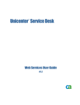
Example of Redundant Server Behavior
(Automatic Server Redundancy)
1
Point, Alarm, User
Registration Data
Primary server (A),
connected to a
conveyor belt PLC
and viewer, is
active.
CB_PLC
A
(A) transmits
point,
alarm and user
registration data to
secondary server
(B).
( B) is connected
on standby.
2
B
Database Logging
Alarm Viewer
Base Control Engine
Point Manager
User Registration
Standby
Primary Server
(A) is down.
Secondary server
(B) automatically
controls all
functions.
CB_PLC
B
A
Offline
Database Logging
Alarm Viewer
Base Control Engine
Point Manager
User Registration
Important: Applications affected by duplicated point values are not supported7.
When the primary server is restarted, resynchronization takes place:
7
1.
The primary server immediately updates user registration and alarm data from
the secondary server while it automatically takes over these functions.
2.
A CIMPLICITY System manager issues a manual command for the primary
server to take over point management and device communication.
3.
The primary server:
§
Collects point data from the secondary server
§
Takes control of point management and device communication
Normally CIMPLICITY reports point values as they change. After a failover, CIMPLCITY sends all the current
point values to all interested applications regardless of whether the value has changed. For example, events that
trigger off the point value being equal to some value may trigger again. It is your responsibility to design the
project to function properly under these circumstances.
2-10
CIMPLICITY HMI Server Redundancy Operation Manual–July 2001
GFK-1353F
4.
The secondary server returns to standby mode.
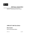
Transfer of Control When the Primary Server is Restarted
(Automatic Server Redundancy)
1
As the primary server
(A) restarts, it takes
control of alarm and
user registration data
from the secondary
server (B).
Alarm, User
Registration data
CB_PLC
B
A
2
System Manager
issues manual
command to restore
control to (A).
Database Logging
Base Control Engine
Point Manager
Point Data
CB_PLC
(A) collects updated
point data from (B) as
it takes control of the
Point Management.
A
B
3
Alarm Viewer
User Registration
Database Logging
Alarm Viewer
Base Control Engine
User Registration
Primary server (A)
becomes active.
Point Manager
Collected Data
(A) sends
alarm, user
registration and point
data to secondary
server (B).
CB_PLC
A
B
(B) is on standby.
GFK-1353F
Database Logging
Alarm Viewer
Base Control Engine
Point Manager
User Registration
Reviewing Server Redundancy
Standby
2-11
Reviewing Setpoint Use in Server Redundancy
Users can make setpoint requests on either the primary or secondary server via:
§
Point Control Panel
§
CimView
§
Automatic Control Functions (Event Manager, Custom Programs)
While the primary server is running, all setpoints from the secondary server except those
from the Automatic Control Function will be routed to the primary computer. All
setpoint originating from Automatic Control Functions on the secondary will be
discarded when the primary is in control.
Let’s consider the case of the Event Manager. The Event Manager runs on both the
primary and secondary computers. Events are triggered on both the primary and
secondary computers. All setpoint requests invoked from the action or script tied to the
event will be ignored on the slave computer. In other words, your scripts execute in
tandem on both computers, but the output to the points is processed only on the master
computer.
A Custom Program would be a PTMAP API program written by you that executes as a
resident process within CIMPLICITY. Setpoints originating from this program will work
the same as the Event Manager.
Reviewing Database Logging in Server Redundancy
When the primary server is in control, both the primary and the secondary server log
alarm and point data into their separate databases. As a result, if the primary fails the
secondary computer can continue to log data without loss of information.
When you bring a server back on line after a failure, a datamerge.exe utility:
1.
Executes a merge from the primary to the secondary server.
2.
Executes a merge from the secondary to the primary server.
See Recovery Procedures in this manual for more information.
The ability to conduct an accurate merge begins with your configuration.
Guidelines for Redundant Logged Database Identification
When you set up your redundant logged database configuration, you have to make sure
that both the primary and secondary servers know where to log their own data. You also
have to make sure that the primary server knows where the secondary server is logging
data, in case it needs to access the secondary logged database after a failure.
When setting up redundant logged databases:
2-12
1.
Set up the same database on the primary and secondary servers so you will have
two actual databases that, under normal operation, will be identical.
2.
Give the database on each redundant server:
§
The same name as the database on the other server
§
A different name Data Source Name (DSN) from the corresponding DSN
on the other server
CIMPLICITY HMI Server Redundancy Operation Manual–July 2001
GFK-1353F
3.
4.
Set up the primary server to point to:
§
Its own database
§
The database on the secondary server
Set up the secondary server to point to its own database
Example of Redundant Logged Database Identification (conceptual)
Logged Source Name/
Logged Database Name
Primary Server
Secondary Server
A = Primary Alarm Source/
Alarm Database
A
B = Primary Point Source/
Point Database
B
C = Secondary Alarm Source/
Alarm Database
C
D = Secondary Point Source/
Point Database
D
See "Redundancy Configuration Procedures" in this manual for configuration
details.
Important: Viewer applications, such as Trending, that use logged data from a server
will not fail over to the database on the redundant server.
GFK-1353F
Reviewing Server Redundancy
2-13
Defining Alarm Management Behavior in Server Redundancy
The Alarm Manager on the primary server receives its updates from
CIMPLICITY services on both the primary and secondary servers.
CIMPLICITY applications that generate alarms (Point Management, Event
Manager8 etc.) will not generate alarms when the corresponding application is
running on the primary server.
Exceptions to this rule are:
§
Device communications alarms.
§
Process down alarms.
§
Node lost alarms.
Defining User Registration in Server Redundancy
A runtime database for users is maintained by User Registration on the primary
server. This information is passed to User Registration on the secondary server.
Defining CimView Behavior in Server Redundancy
CimView applications running on the primary server or viewers receive point updates
from the primary point manager. CimView applications running on secondary server
receives updates from the point manager running on the secondary server. All setpoints
are routed to the primary point manager. When the primary server is lost, CimView
applications on viewers automatically begin receiving updates from the secondary point
manager.
Important: Trend Controls on CimView screens that use logged data will not fail over
to the database on the redundant server.
Defining Failover Period in a Server
CIMPLICITY Interprocess Communications has a built-in probing mechanism,
independent of TCP/IP’s network probing mechanism. This was introduced so that you
can configure a smaller failover period than the TCP/IP default timeout period of 2 hours.
This expedites detection of a failed node for Server Redundancy. The default time out is
15 seconds.
8
From a Basic Script running in the Event Manager there is a way to force an alarm to be generated when executed
on the Slave Computer. Consult the documentation for AlarmGenerate in the Basic Control Engine Language
Reference Manual.
2-14
CIMPLICITY HMI Server Redundancy Operation Manual–July 2001
GFK-1353F
Manual Redundancy Overview
Although automatic server redundancy is an essential feature of CIMPLICITY HMI, it
requires total failure of the primary server for the secondary server to take over. There are
specific failures when you need the secondary server to take over a function or the entire
project, even when the primary server has not failed. Therefore server redundancy
provides an application interface to allow you to trigger a failover when a specific criteria
is reached.
There may be a failure involving the primary server with the:
§
§
Software, when for some reason, the:
è
Data collection stops
è
Project goes down, even though the server continues to function
Device communication, when the:
è
Device connection to Point Management (PTM) is severed
è
All devices, Alarm Manger (AM), User Registration (UR) and Point
Management (PTM) applications lose contact with the processes
Functions to Address Specific Failures
CIMPLICITY HMI offers four functions to address these issues. They are:
For software failure:
1.
Point management transfer, including data collection
2.
Entire project fail over
For device failure:
1.
Point management transfer
2.
Entire project fail over
The functions reside in the Redundancy.dll and can be called by any programming
language, like the Basic Control Engine, that is capable of calling a DLL entry point.
The functions are:
COR_BOOLEAN failover_project(COR_STATUS *retstat)
Causes the local project to shutdown.
COR_BOOLEAN failover_data_collection(COR_STATUS *retstat)
Causes the current slave computer to become the current master computer.
COR_BOOLEAN redundant_is_redundant()
Tells if this is a redundant project.
int redundant_local_index()
Returns the index of the global point element that has the status of the local device.
GFK-1353F
Returns
If on the
0
Primary
1
Secondary.
Reviewing Server Redundancy
2-15
int redundant_remote_index()
Returns the index of the global point element that has the status of the remote device
Returns
If on the
0
Primary
1
Secondary.
You, the system manager, will configure a specific global point and provide the logic to
determine when a changeover will occur. Basically the logic can be whatever you want,
as long as it is running as part of the project.
Note: Aids that are in your CIMPLICITY HMI directory, if you installed the server
redundancy option include:
§
Mon_failure.c, a sample program to review as a working example. It is located
at:
…\CIMPLICITY\Hmi\api\redundant_api\mon_failure.c
§
Redundancy.h, a “C” header file that contains the prototypes for the function. It
is located at:
…\CIMPLICITY\Hmi\include\inc_path\redundancy.h
Tools for Device Failure
The devcom toolkit provides the current status of a device connection to Point
Management (PTM). Whenever the status of the connection changes the devcom will
send a message to Point Management.
Point Management will set a global point based on the status of the device connection.
If there is a failure in the:
Devcom
All the devices for the devcom are marked unavailable
Remote PTM
All of the remote devices are marked unavailable
Local PTM
The application fails over to the remote PTM
The remote PTM marks the local devices as unavailable
A global BOOLEAN array point of two (2) elements indicates the status of the device
connection.
2-16
The value of:
Indicates that the devcom:
1
Is communicating with the device
0
Is not communicating with the device
CIMPLICITY HMI Server Redundancy Operation Manual–July 2001
GFK-1353F
Adhering to Point Requirements for Manual Server Redundancy
The point you create to determine when either data collection or the entire project should
be transferred to the secondary server is very specific. It must meet four conditions. It
must:
1.
Have the same name as the name of the device.
2.
Be a Boolean point.
3.
Have two (2) elements (for example, the status of the device on the primary
server and the status of the device on the secondary server).
4.
Be a global point.
Transferring Point Management Manually (Including Data
Collection)
In a normal state the primary server carries out several processes that can be classified as
point management.
Point management includes:
§
Data collection
§
Virtual point processing
§
Sending information to CimView screens
If the primary server stops collecting data from one device, but is still running and
communicating with the secondary computer, there is no automatic fail over.
Under these circumstances or for whatever reasons you specify, you can manually
transfer point management from the primary to the secondary server.
After the transfer the:
§
Primary server maintains control of processes such as:
Software
è
Database logging
è
Alarm viewer
è
Base control engine
Devcom
§
è
Alarm Manager (AM)
è
User Registration (UR)
è
Point Management (PTM)
Secondary server takes over point management
To manually transfer point management from the primary to secondary
server:
1.
Create a specific Boolean point with the same name as the device being
monitored.
2.
Call this function:
failover_data_collection()
3.
GFK-1353F
Specify what actions should occur if the point changes from 1 to 0 through a
Basic script.
Reviewing Server Redundancy
2-17
Example
Your primary server is connected to a PLC for a conveyor belt called CB_PLC and a
CimView screen.
You have configured a global Boolean point called CB_PLC that:
§
Monitors the status of the device on the primary server
§
Is on standby on the secondary server
§
Alerts the system manager, if it changes from 1 to 0
The primary server stops collecting data from the CB_PLC device.
The system manager is alerted and switches data collection to the secondary server.
The secondary server takes over point management function.
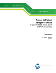
Example of Manual Data Collection Transfer Function
(Manual Server Redundancy)
1
Primary server (A)
stops collecting
data from a
conveyor belt PLC
named CB_PLC.
CB_PLC
A
Boolean point
CB_PLC changes
from 1 to 0.
2
Point CB_PLC script
activates a warning to the
System Manager when the
point changes from 1 to 0.
3
System Manager issues
manual command to switch
over data collection.
4
Primary server (A) is
still active.
B
Database Logging
Alarm Viewer
Base Control Engine
Point Manager
User Registration
Secondary server (B)
takes over point
management.
Standby
CB_PLC
A
B
2-18
Point Manager
Database Logging
Alarm Viewer
Base Control Engine
User Registration
CIMPLICITY HMI Server Redundancy Operation Manual–July 2001
GFK-1353F
Forcing Manual Project Transfer
In a normal state the primary server is the active server.
The active server controls all the processes in the project.
If the primary server loses contact with one device, but is still running and
communicating with the secondary server, there is no automatic fail over.
Under these circumstances or, for whatever reasons you specify, you can manually force
a fail over from the primary to the secondary server.
To manually force a project transfer:
1.
Create a specific Boolean point with the same name as the device being
monitored.
2.
Call the function:
failover_project ()
3.
Specify what actions should occur if the point changes from 1 to 0 through a
Basic script.
Example
Your primary server is connected to a PLC for a conveyor belt called CB_PLC and a
CimView screen.
You have configured a global Boolean point called CB_PLC that:
§
Monitors the status of the device on the primary server
§
Is on standby on the secondary server
§
Alerts the system manager, if it changes from 1 to 0
The primary server loses connection with the CB_PLC device.
The system manager is alerted and fails over the entire project from the primary to the
secondary server.
GFK-1353F
Reviewing Server Redundancy
2-19
The secondary server takes over the primary server role.
Example of Manual Project Failover Function
(Manual Server Redundancy)
1
Primary server (A)
loses connection
with Conveyor belt
PLC
named CB_PLC.
Boolean point
CB_PLC changes
from 1 to 0.
2
Point CB_PLC script
activates a warning to the
System Manager when the
point changes from 1 to 0.
3
System Manager issues
manual command to fail
over the project from A to B.
4
Primary server
(A) is off line.
CB_PLC
A
B
Standby
Database Logging
Alarm Viewer
Base Control Engine
Point Manager
User Registration
Secondary server
(B) becomes
active.
CB_PLC
B
A
Off line
2-20
Database Logging
Alarm Viewer
Base Control Engine
Point Manager
User Registration
CIMPLICITY HMI Server Redundancy Operation Manual–July 2001
GFK-1353F
Configuring Server Redundancy
About Redundancy Configuration Procedures
This chapter documents the configuration procedures needed to support Server
Redundancy for CIMPLICITY HMI for Windows NT.
Before you begin configuration, make sure that the same version of CIMPLICITY
software is installed and licensed on both servers of each redundant pair as described in
the CIMPLICITY Base System User Manual (GFK-1180). In addition, you must install all
required application options, protocols and databases software on both computers.
Review:
§
Base System configuration.
§
Database logging configuration.
Base System Configuration
Configure the base system in the following order. :
Configure:
1.
A project.
2.
A network and verify configuration.
3.
Device communications.
Important: You need to install the redundancy option on all Viewers.
Note: Global points are obsolete in CIMPLICITY 5.0. Instead use the points that are
created in the redundancy object. See the "Using the Redundancy Object" chapter in this
manual for details.
GFK-1353F
3-1
1. Configure a Project for Server Redundancy
The first step in using server redundancy is to configure your project to be redundant.
You use the Project Properties dialog box to tell the primary server where to send files
and screens and collect data (after a failure) from the secondary server.
Step 1. Configure a project to be redundant:
1.
Select Project on the Workbench menu bar.
2.
Select Settings.
The Project Properties dialog box appears.
3-2
3.
Select the General tab.
4.
Check Server Redundancy in the Options box.
5.
Select the Redundancy tab.
CIMPLICITY HMI Server Redundancy Operation Manual–July 2001
GFK-1353F
6.
Enter the following information in the Redundancy tab:
Computer name
Enter the name of the secondary Server.
Project path
Enter the directory on the secondary Server
where the CIMPLICITY project will be stored.
The drive must be a mapped drive on the primary
server.
UNC filenames are not supported.
Configuration files and screens are copied from the primary server to the Project
path whenever a Configuration Update is performed.
Important: Make sure you configure the logging setup on both the primary and
secondary server through the Database Logger in the CIMPLICITY HMI Workbench. See
"Managing Database Logging" in the CIMPLICITY HMI Base System User's Manual.
2. Configure Networks for Server Redundancy
The second step when configuring a base system for server redundancy is to configure
and verify the network.
Configuration includes host names.
Important: SR requires that all computers (primary, secondary and viewer) must have
their names and IP addresses configured and these names must match the actual computer
names. You may configure the host names in DNS, WINS or in the local host file on
each computer, depending on the networking resources available at your site. SR will not
function correctly if this information is not configured. If you do not understand network
configuration you should obtain the services of someone that does.
Once the configuration is complete, the following tests should be run.
1.
From the primary computer ping primary, secondary and all viewers by name
and by address.
2.
From the secondary computer ping primary, secondary and all viewers by name
and by address.
3.
From each viewer, ping primary and secondary by name and address.
4.
Verify computer names of each computer match.
Note: Keep alives are automatically configured on a:
§
Server when redundancy is installed and
§
Viewer when Viewer redundancy is installed.
The following example demonstrates how to ping by name, by address and determine the
computer name.
GFK-1353F
Configuring Server Redundancy
3-3
C:\WINNT\system32>ping albsagp2
Pinging albsagp2 [3.26.4.215] with 32 bytes of data:
Reply from 3.26.4.215: bytes=32 time<10ms TTL=128
Reply from 3.26.4.215: bytes=32 time<10ms TTL=128
Reply from 3.26.4.215: bytes=32 time<10ms TTL=128
C:\WINNT\system32>ping -a 3.26.4.215
Pinging ALBSAGP2 [3.26.4.215] with 32 bytes of data:
Reply from 3.26.4.215: bytes=32 time<10ms TTL=128
Reply from 3.26.4.215: bytes=32 time<10ms TTL=128
Reply from 3.26.4.215: bytes=32 time<10ms TTL=128
C:\WINNT\system32>set computername
COMPUTERNAME=ALBSAGP2
C:\WINNT\system32>
To verify names using the above example as a reference.
To Verify Names
Referencing the Above Example
Ping by Name
ping albsagp2 first translates albsagp2 to an IP
Address and then verifies communication to the
computer.
albsagp2 has an IP address of 3.26.4.215.
The time required to Ping must be less than 10ms between
primary and secondary and less than 30ms between
viewers.
This step verifies that the network software can convert a
hostname to an IP Address.
Ping by Address
Type ping –a 3.26.4.215.
The output of ping albsagp2 provides the IP Address.
This step verifies that the network software can convert
the IP Address back to the same node name as entered in
the first step. If you obtain a different IP Address back
this may indicate that you have duplicate entries for the IP
Address in you network lookup tables. This must be
corrected before continuing.
Continue Pinging
In this example we just ping one computer.
You would continue to ping the other computers
(secondary, viewers, etc)
Check Computer Names
Type set computername to return the current setting.
This final step on each computer is determines if the
system's computer name is the same as the computer
name configured in the network. This setting must match
the name returned in the above two tests. If not this must
be corrected by either changing your computername or
changing the network software configuration before
continuing.
3-4
CIMPLICITY HMI Server Redundancy Operation Manual–July 2001
GFK-1353F
3. Configure Device Communications for Server Redundancy
Specific Device Communications configuration such a driver or interface card
configuration will need to be configured and tested on the secondary before starting
redundancy. Consult the appropriate device communications manual for additional
details.
Unsolicited Data
The Device Communications module receives and processes unsolicited data reported
from factory devices.
Unsolicited data must be directed to the to the secondary server in addition to the primary
server, so it can be processed by the Device Communications/Point Manager on the
secondary server when the primary server fails.
4. Configure Global Points for Server Redundancies
The next step is to configure virtual points to track redundant server status during system
operation. The points have the following requirements:
§
Naming convention is:
è
MASTER_PTM_RP for the primary server
è
SLAVE_PTM_RP for the secondary server
§
Type is virtual
§
Class is Digital
§
Calculation for the point is None (default).
A point will take on a value of:
§
1 if the server it represents is currently operating as the primary server
§
0 if the server is the secondary server
The current Primary Point Manager will only change the values. This implies that point
updates to the global points will occur when:
§
There is a redundant server failure
§
Redundant servers are synchronized at startup
§
An orderly transition from secondary to primary server occurs.
Important: If you are using point lines in Trending that automatically look for the data
source, you must configure MASTER_PTM_RP and SLAVE_PTM_RP. These are the points
that Trending needs to failover to the secondary server if the primary is down.
GFK-1353F
Configuring Server Redundancy
3-5
Database Logging Configuration
When you set up the same database on the primary and secondary server (so you will
have two actual databases that, under normal operation, will be identical) you need to
identify them for data logging. You do this by making entries in the:
§
Windows ODBC Data Source Administrator dialog box
§
CIMPLICITY HMI Logging Properties dialog box.
In logged database redundancy, you need to configure CIMPLICITY logging redundancy
on both the primary and secondary server through Windows NTcontrol panels.
Configuring Windows ODBC Data Source Administrator
Important: Viewer applications, such as Trending, that use logged data from a primary
server will not fail over to the database on the redundant server.
Caution: On the primary server, make sure you have specified the redundant server in
the CIMPLICITY HMI Workbench under Settings found on the Workbench menu bar.
Redundant Database Setup Using an SQL Server
Follow procedures for five basic steps to configure, in the ODBC Data Source
Administrator, a redundant database setup using an SQL server. The steps are:
Step 1.
Display the System DSN tab. See page 3-7.
Step 2.
Select the driver for a new data source. See page 3-8.
Step 3.
Configure the primary data source on the primary server. See page 3-8.
Step 4.
Configure the secondary data source on the primary server. See page 3-12.
Step 5
Repeat Steps 1-4 on the secondary server.
When you complete this setup, go to the Logging Properties dialog box in the
CIMPLICITY Workbench to identify the files you have set up. See page 3-15 for details.
3-6
CIMPLICITY HMI Server Redundancy Operation Manual–July 2001
GFK-1353F
Step 1. Display the System DSN Tab
1.
Click the ODBC icon in the Windows NT Control Panel.
The ODBC Data Source Administrator dialog box appears.
2.
Select the System DSN tab.
The first time you select the System DSN tab, it will have the same
CIMPLICITY SQL Server entry on both the primary and secondary server. It is
called CIMPLICITY SQL Server Logging.
SQL Server Logging
GFK-1353F
Configuring Server Redundancy
3-7
Step 2. Select the Driver for a New Data Source
If the data source and driver you need displays on the System DSN tab, go to
Step 3.
1.
Click Add on the System DSN tab.
The Create New Data Source dialog box opens and displays a list of drivers
installed in your network, from which you select the appropriate driver.
2.
Select the driver.
3.
Click Finish .
Result: An ODBC SQL Server dialog box appears in which you begin to set up the
data source.
Step 3. Configure the Primary Data Source on the Primary
Server
On the Primary server
(Go to 2 if you are creating a new data source and have just completed Step 1.)
1.
Click Configure on the System DSN tab of the ODBC Data Source
Administrator dialog box, if you are configuring a driver that already exists.
An ODBC SQL Server dialog box dialog box appears if you clicked Configure
or if you selected a new driver in the Create New Data Source dialog box (Step
2).
2.
Enter specifications in the first Create a new Data Source to SQL Server dialog
box as follows:
A. Enter a unique Name for the primary server data source. This name can be
local.
B. (Optional) Enter a description of the source.
C. Select the primary server from the drop down menu in the Server field.
3-8
CIMPLICITY HMI Server Redundancy Operation Manual–July 2001
GFK-1353F
(Optional) Enter a description.
Enter a unique name.
Select the primary server.
3.
Click Next.
4.
Enter specifications in the second Create a new Data Source to SQL Server
dialog box as follows:
A. Check With SQL Server authentication using a login ID and password
entered by the user.
B. Check Connect to SQL Server to obtain default settings for the
additional configuration options.
The Login ID and Password fields are enabled.
C. Enter the ID required to access to database in the Login ID field.
D. Enter the password required to access the database in the Password field.
Enter the required Login ID and password for
access to the database.
5.
Click Next.
4.
Enter specifications in the third Create a New Data Source to SQL Server dialog
box as follows:
A. Check Change the default database to.
GFK-1353F
Configuring Server Redundancy
3-9
B. Select the name of the default database for any connection made using this
data source from the drop down list.
Select the default database.
5.
Click Next.
6.
Enter specifications in the fourth Create a New Data Source to SQL Server
dialog box as follows:
Check Perform translation for character data.
3-10
CIMPLICITY HMI Server Redundancy Operation Manual–July 2001
GFK-1353F
7.
Click Finish.
An ODBC Microsoft SQL Server Setup screen displays the details of your
configuration.
7.
Click OK if the specifications are correct.
Result: The SQL Server data source is created and displays in the Data Source list
on the System DSN tab.
GFK-1353F
Configuring Server Redundancy
3-11
Step 4. Configure the Secondary Data Source on the Primary
Server
On the Primary server
(Go to 2 if you are creating a new data source and have just completed Step 1.)
1.
Click Configure on the System DSN tab of the ODBC Data Source
Administrator dialog box, if you are configuring a driver that already exists.
An ODBC SQL Server dialog box dialog box appears if you clicked Configure
or if you selected a new driver in the Create New Data Source dialog box (Step
2).
2.
Enter specifications in the first Create a new Data Source to SQL Server dialog
box as follows:
A. Enter a unique Name for the secondary server data source. This name can
be local.
B. (Optional) Enter a description of the source.
C. Select the server that will be the secondary server from the drop down menu
in the Server field.
(Optional) Enter a description.
Enter a unique name.
Select the secondary server.
3.
Click Next.
4.
Enter specifications in the second Create a new Data Source to SQL Server
dialog box as follows::
A. Check With SQL Server authentication using a login ID and password
entered by the user.
B. Check Connect to SQL Server to obtain default settings for the
additional configuration options.
The Login ID and Password fields are enabled.
C. Enter the ID required to access to database in the Login ID field.
3-12
CIMPLICITY HMI Server Redundancy Operation Manual–July 2001
GFK-1353F
D. Enter the password required to access the database in the Password field.
Enter the required Login ID and password for
access to the database.
5.
Click Next.
4.
Enter specifications in the third Create a new Data Source to SQL Server dialog
box as follows::
A. Check Change the default database to.
B. Select the name of the default database for any connection made using this
data source from the drop down list.
Select the default database.
GFK-1353F
5.
Click Next.
6.
Enter specifications in the fourth Create a new Data Source to SQL Server
dialog box as follows:
Configuring Server Redundancy
3-13
Check Perform translation for character data.
7.
Click Finish.
An ODBC Microsoft SQL Server Setup screen displays the details of your
configuration.
7.
3-14
Click OK if the specifications are correct.
CIMPLICITY HMI Server Redundancy Operation Manual–July 2001
GFK-1353F
Result: The SQL Server data source is created and displays in the Data Source list
on the System DSN tab.
Configuring the Logging Properties Dialog Box
In order to identify the database logger files in your CIMPLICITY project, you specify
the source of both the primary server and secondary server database logger files through
the CIMPLICITY HMI Project Properties dialog box located on the primary server.
To identify the database logger data source in a CIMPLICITY HMI project:
1.
Click Project on the Workbench menu bar.
2.
Select Properties.
3.
Select the Settings tab.
4.
Select Database Logger.
5.
Click Settings.
The Logging Properties dialog box opens:
6.
GFK-1353F
Select the Point Connection - Master tab.
Configuring Server Redundancy
3-15
7.
Select a SQL Server ODBC data source from the drop down menu of
available data sources that is the data source for that server.
Tip: Click the ODBC Data Source button
to the right of the ODBC data
source field to open the ODBC Data Source Administrator dialog box. You can
then see the drivers configured with each data source and make any necessary
changes or additions.
ODBC Data Source
Administrator
System DSN Tab
displays the driver
configured for each data
source.
8.
Enter the Database user needed to connect to the selected database driver.
This field is required if you are connecting to a SQL Server.
9.
Enter the Password needed to connect to the selected database driver. This
field is required if you are connecting to an SQL Server.
10. Enter the Reconnect wait period, which is amount of time the Database
Logger waits between reconnect attempts when the connection to the database is
lost in the. The default is 30 seconds. Enter a value between 0 seconds
(continuous retries) and 24 hours.
3-16
CIMPLICITY HMI Server Redundancy Operation Manual–July 2001
GFK-1353F
11. Check the Enable Store and Forward check box to enable Store and Forward.
After you enable the feature, use the radio buttons to select between unlimited or
limited storage of database records.
Unlimited
Database Logger stores an unlimited number
of records while its connection to the
database is down. The number of records
actually stored is determined by the amount
of time the connection is lost and by the
amount of free disk space you have.
Max number of stored records
Database Logger stores a specified number
of records when its connection to the
database is down. Enter a number between 1
and 4,294,967,295.
12. Repeat these steps for the other three tabs so you will have configured all four
tabs:
Point Connection - Master
Primary (master)
Point Connection - Slave
Second (slave)
Alarm Connection - Master
Primary
Alarm Connection - Slave
Second
13. Click OK or select the Parameters tab.
Result: CIMPLICITY validates your entries. If the Data Logger is unable to
connect to the selected database, validation fails.
Important: On each tab, make sure that you select the correct data source for the
computer (master / slave) that the tab represents.
Guidelines and notes about specific data sources:
1.
CIMPLICITY SQL Server Logging
A Microsoft SQL Server data source that logs data to an on-node SQL Server
database. You must install SQL Server (sold separately) to use this data source.
If you are connecting to a SQL Server, you may be prompted for a database
name during validation.
2.
Oracle Database
You may see the ODBC data source that you created for Oracle.
You may be prompted for a Server ID during validation. Enter the Alias Name
for the Oracle database in this field.
GFK-1353F
Configuring Server Redundancy
3-17
Using the Redundancy Object
About the Redundancy Object
When you activate the server redundancy option in the Workbench, CIMPLICITY
automatically installs a Redundancy object, which is an object of the redundancy class.
The Redundancy object enables you to easily:
§
View whether or not the primary and/or secondary server is running,
§
Switch the master role from one server to the other when you need to take the
current master offline,
§
Switch the master back when the original master is brought back on line and
§
Configures a set of point to use in your application.
This capability enables you to efficiently switch control back and forth while ensuring
that data is not lost.
CIMPLICITY Redundancy object
§ Displays which
server is the
current master.
§ Enables you to
switch the
master role
from one server
to the other
GFK-1353F
4-1
Reviewing the Redundancy Object Components
When you enable the server redundancy option CIMPLICITY automatically creates the
following.
1.
GefRedundancy class.
GEFRedundancy Class (Automatically Created)
2.
Redundancy object.
Redundancy Object (Automatically Created)
3.
CIMPLICITY Redundancy object points as follows:
REDUNDANCY.PRI_ACTIVE
Primary computer is active.
(i.e. CIMPLICITY is running on
the primary computer.)
REDUNDANCY.PRI_MASTER
Primary computer is the master.
REDUNDANCY.RESTORE_PRIMARY
When set to 1(by a button on the
Redundancy CimView screen), the
master is switched to the primary
computer.
REDUNDANCY.SEC_ACTIVE
Secondary computer is active.
(i.e. CIMPLICITY is running on
the secondary computer.)
4-2
REDUNDANCY.SEC_MASTER
Secondary computer is the master.
REDUNDANCY.SWITCH_TO_SEC
When set to 1(by a button on the
Redundancy CimView screen), the
master is switched to the secondary
computer.
CIMPLICITY HMI Server Redundancy Operation Manual–July 2001
GFK-1353F
Redundancy Object Points
4.
GefRedundancy CimEdit/CimView screen.
Redundancy CimView Screen (Automatically Created)
Note: You do not have to do any configuration for the redundancy class and object
object. CIMPLICITY does it all for you.
See the "Configuring Classes" chapter in the CIMPLICITY Base System User's Manual,
GFK-1180, for information about CIMPLICITY classes.
GFK-1353F
Using the Redundancy Object
4-3
Redundancy Object Use
The Redundancy object is straightforward to use.
Steps to use the Redundancy object are:
Step 1.
Display the Redundancy CimView screen.
Step 2.
Monitor the servers through the Redundancy screen.
Step 3.
Switch the master role between redundant computers.
Step 1. Display the Redundancy CimView Screen
The Redundancy CimView screen is configured and ready for use.
Step 1. Display the Redundancy CimView screen:
1.
Make sure the project is running on the local computer.
2.
Select the Objects icon in the Workbench left pane.
3.
Right-click the Redundancy object in the Workbench right pane.
4.
Select Quick View from the popup menu.
Select Quick View to display the
Redundancy CimView screen.
Result: The Redundancy CimView screen appears.
4-4
CIMPLICITY HMI Server Redundancy Operation Manual–July 2001
GFK-1353F
Step 2. Monitor the Servers through the Redundancy Screen
Once the Redundancy CimView screen displays for the project, you can review which:
§
Computers are running.
§
Computer is the master.
§
Computer is the slave.
If both computers have the same project version running a Switch button displays that
enables you to switch the master role from one to the other.
Redundancy CimView Screen: Example
1
2
3
Both computers are running. The:
1 Primary is the master.
2 Secondary is the slave
3 Switch button enables you to switch the master role to
the secondary.
4 Primary computer name.
5 Secondary computer name.
GFK-1353F
Using the Redundancy Object
4-5
Step 3. Switch the Master Role between Redundant Computers
Click the Switch button to switch the master role from one computer to the other.
An example of a progression of actions using the Redundancy CimView screen is as
follows.
Example: Using the Redundancy Object CimView Screen
The secondary computer the master and the primary computer is offline.
1.
View the Redundancy CimView screen the secondary computer.
The secondary computer displays as the master; the primary computer displays
as the slave and offline.
2.
Bring the primary computer back online.
3.
Restart the CIMPLICITY project.
4.
View the Redundancy object on the primary computer.
The primary computer displays as the slave and online.
A Switch button appears.
4-6
CIMPLICITY HMI Server Redundancy Operation Manual–July 2001
GFK-1353F
2.
Click Switch.
The primary computer is the master; the secondary computer is the slave.
End of example.
GFK-1353F
Using the Redundancy Object
4-7
Recovery Procedures
Normal Operating Procedures
Normal operating procedures in server redundancy involve:
§
Run and stop redundant CIMPLICITY projects.
§
Starting a project from the secondary server.
§
Configuring the project to start on both the primary and secondary servers when
they power up.
This section describes how to insure that the operating procedures perform
smoothly.
Starting and Stopping Redundant CIMPLICITY Projects
When all hardware is working correctly, CIMPLICITY software can be started and shut
down using the Run and Stop tools in the CIMPLICITY Workbench on the primary
server.
Important: Under most circumstances you should use the Workbench to start redundant
projects. This is because the Workbench:
1.
Allows you to start up both systems in one coordinated action. (If you use
CIMPLICITY Options to startup on the primary, you need to wait for the
primary to finish its startup and then start the secondary.)
2.
Will update the slave node configuration as required before starting the project,
making sure that the master and slave nodes are synchronized.
A rare exception to normal startup occurs if, there is a catastrophic event that forces both
computers to shut down, e.g. the power failed. In this situation, the last active master must
be the first restarted to ensure data integrity in the following areas:
§
Manual mode data and values.
§
Saved point values.
If, the secondary server was the only computer running before shutting down, it should
start first, as the master. Data that was collected before the shutdown can then be failed
over to the primary server before it is reinstated as the master.
GFK-1353F
5-1
Tip: If one project is running and one is stopped both the Run and Stop buttons on the
Workbench toolbar are active
running.
. Click either button to determine which project is
To start a redundant project:
1.
Do one of the following:
Method 1
A. Click Project on the Workbench menu bar.
B. Select Run.
Method 2
Click the Run button
on the Workbench toolbar.
The Redundant project stop dialog box opens when you use either method.
The buttons are dimmed for servers that are running.
2.
Select Run.
The Start Redundant Project dialog box opens.
3.
4.
5-2
Select one of the following:
§
Primary & Secondary to start the project on both the primary and
secondary servers
§
Primary only to start the project only on the primary server
§
Secondary only to start the project only on the secondary server
Click Start to start the project.
CIMPLICITY HMI Server Redundancy Operation Manual–July 2001
GFK-1353F
To stop a redundant project:
1.
Do one of the following:
Method 1
A. Click Project on the Workbench menu bar.
B. Select Stop.
Method 2
Click the Stop button
on the Workbench toolbar.
The Stop Redundant Project dialog box opens.
The buttons are dimmed for servers that are not running.
Stop a Redundant Project Example
The primary server
is running.
The secondary
server is not
running.
3.
4.
Select one of the following:
§
Primary & Secondary to stop the project on both the primary and
secondary servers.
§
Primary only to stop the project only on the primary server.
§
Secondary only to stop the project only on the secondary server.
Click Stop to stop the project.
Starting the Project from the Secondary Server
In case the primary computer is unavailable, the project can be started on the secondary
from the secondary computer. Starting the project simultaneously on both computers is
not supported and will cause problems.
To start CIMPLICITY from the secondary server:
GFK-1353F
1.
Open the CIMPLICITY Options dialog box.
2.
Select the project file from the project directory on the secondary computer
3.
Click Start.
Recovery Procedures
5-3
Configuring the Project to Start at Boot
The project can be configured to start on both the primary and secondary computers when
they power up.
Important: Make sure that the projects do not start at the same time if they are
configured to start on both the primary and secondary computers when they power up.
Failure to ensure this can result in both computers considering themselves the master.
To provide a mechanism for dealing with a Power On situation where both computers
boot at the same time you can configure a parameter to delay the secondary computer's
startup until the primary is complete.
To delay the secondary computer's startup until the primary is running:
Configure the following global parameter in the project.
SLAVE_STARTUP_TIMOUT|1|<TIME-MINUTES>
Where
Time-minutes
Is the amount of time it takes for the project to start on the primary
computer plus an additional minute.
This value you empirically determine by measuring the startup time on
the master.
See the appendix "Configuration Parameters" in this manual for more details about
server redundancy configuration parameters.
Note: It is recommended that you use the Workbench to start redundant projects.
5-4
CIMPLICITY HMI Server Redundancy Operation Manual–July 2001
GFK-1353F
Primary Server Failure
When the server fails in automatic server redundancy, the secondary server automatically
takes control. Then, you, the system manager, have to:
§
Find the cause of the problem.
§
Reset the primary server after recovery.
§
Synchronize database logging files.
When you have finished, redundancy will return to normal.
Understanding System Operation during Failover
When the primary server of a redundant pair fails, the secondary server goes from standby
to active mode to insure that all essential areas in the project continue to operate.
Areas include:
§
Device communications and point management.
§
Alarm management.
§
User logons.
§
Runtime interfaces.
Device Communications and Point Management
Device Communications on the secondary server begins actively polling for data and
passes point data to the Point Manager on the secondary server, which now becomes the
primary Point Manager. Any viewer process that was connected to the original primary
Point Manager will automatically switch over to the new primary Point Manager, which
will now assume all supervisory and control functions.
Note: Between the time that the primary server is lost and before the secondary server
takes over, users may notice an interruption in system performance. During this time,
point values will not be updated, setpoints and alarm acknowledgments will not complete,
and users will not be able to log on or off.
Alarm Management
The Alarm Manager on the secondary server becomes the primary Alarm Manager. No
alarm data is lost because the Alarm Manager on the primary server continually updated
the alarm list for the Alarm Manager on the secondary server. The new primary Alarm
Manager will now process all alarm updates and provide alarm information to all
interested processes.
User Logons
The User Registration process on the secondary server becomes the primary User
Registration process. No user registration data is lost because User Registration on the
primary server continually updated the user list for User Registration on the secondary
server. The new primary User Registration will now process all user logins and logouts
and provide information on user views.
GFK-1353F
Recovery Procedures
5-5
Runtime Interfaces
When the primary server fails, all CimView, Alarm Viewer and Point Control Panel
sessions running on that server are lost.
§
CIMPLICITY user interface accessed from console on the primary server.
When the primary server fails, this console is no longer usable. The user will
have to move to the console on the secondary server, log in, and access the
CIMPLICITY user interface from there.
§
CIMPLICITY user interface accessed from a Viewer.
The user interfaces will fail over to the new master.
Detecting the Cause of Primary Server Failure
Server failure may be due to:
§
CIMPLICITY software shutdown on either server
§
Network failure between the primary and secondary servers
§
Loss of server due to loss of power or equipment failure
Server failure is detected by the IPC Router, which is the communications process that
runs on each server.
1.
The Router sets up links to each server in the system and sends messages to each
node at a set interval.
The probe interval is defined in REDUND_PROBE_DELAY which is set to
1000 milliseconds by default.
2.
If no reply is received from the server for a set number of tries (defined in
REDUND_PROBE_COUNT) the server is then declared to have failed.
3.
The Router sends a "Partner Dead" message to any processes that have
outstanding messages to processes on that server.
Server failure may be detected on a primary server, secondary server or Viewer.
5-6
§
When a secondary server fails, functionality is not lost, because all functions are
also running on the primary server.
§
When a primary server fails, the secondary server initiates procedures to take
over redundant CIMPLICITY functions.
CIMPLICITY HMI Server Redundancy Operation Manual–July 2001
GFK-1353F
Resetting the Primary Server after Recovery
After a primary server has failed and recovered, processes on the secondary server need
to be told that the primary sever is now available. The Redundancy object provides a
straightforward way to reset the primary server. CIMPLICITY automatically displays this
object when the redundancy feature is activated.
To reset the primary server on CIMPLICITY:
1.
Make sure that CIMPLICITY software is running on the primary and secondary
servers.
2.
Start a project's Workbench on the primary server.
3.
Select the Objects icon
4.
Right-click the Redundancy object.
5.
Select Quick View from the popup menu.
in the Workbench left pane.
Select Quick View to display the
Redundancy CimView screen.
The Redundancy screen appears displaying the primary computer as the slave
and the secondary as the master.
GFK-1353F
Recovery Procedures
5-7
6.
Click Switch.
Result: The primary server is reset to be the master.
See the "Using the Redundancy Object" chapter in this manual for details about the
Redundancy object.
Note: The Alarm Manager and User Registration on the primary and secondary servers
will automatically resynchronize themselves to their primary and secondary roles when
the primary server initially comes on line.
The following will occur as part of the reset:
§
Device communications modules on the secondary server will stop collecting
data and return to standby mode.
§
The Point Manager on the secondary server resumes its secondary role.
§
All viewer applications will automatically resynchronize to the primary Point
Manager.
The Point Manager on the primary server will resume its primary role, and will initiate
device communications modules on the primary server to start collecting data.
Re-synchronizing Database Logging Files
The Database Logger uses ODBC database tables to store historical data. For Server
redundancy, the same database tables are created on the primary and secondary servers.
Time synchronization works as follows:
One of the redundant servers goes down.
Two ptnr_<timestamp>.log file are generated in the project's \log directory.
§
One on the primary server
§
One on the secondary server
With <timestamp> as the date and time the file was created the
ptnr_<timestamp>.log records on the:
§
5-8
Secondary server–its clocked time when one of the servers went down and
came back up
CIMPLICITY HMI Server Redundancy Operation Manual–July 2001
GFK-1353F
§
Primary server–its clocked time when one of the servers went down and came
back up
These files are then used to synchronize the databases.
To synchronize the databases on the primary and secondary nodes, on the
primary server:
1.
Open the project's Workbench.
2.
Click the Tools menu.
3.
Select Command prompt.
4.
In the Command Prompt dialog box, type:
datamerge
5.
(Optional) Run the datamerge.exe utility with optional parameters to merge
specific times. The command format is:
datamerge.exe [[source] [dest] time1 time2]
where
the parameters are:
source
Name of the source server
dest
Name of the destination server
time1
Start time for merging data
time2
End time for merging data
Important: You can only run datamerge.exe on the primary server - that is, the
server that has all of the ODBC data sources defined. Therefore, the primary server has to
be running before you begin.
As it executes, the datamerge.exe utility:
1.
Reads the ptnr_<timestamp>.log files on the primary and secondary servers.
2.
Determines from the ptnr_<timestamp>.log files in the primary server's \log
directory what data needs to be merged from the primary server's database to the
secondary server's database
3.
Executes the merge from primary to secondary.
4.
Determines from the ptnr_<timestamp>.log files in the secondary server's
\log directory what data needs to be merged from the secondary server's
database to the primary server's database
5.
Executes the merge from secondary to primary.
A db_merge.log file is generated to report the success or failure of the merge.
Note: When you run the datamerge.exe utility with specific start and end times, the
ptnr_timestamp.log files on the secondary and primary servers are not used.
GFK-1353F
Recovery Procedures
5-9
Failure Exceptions for Automatic Server Redundancy
There are two categories of failure exceptions that CIMPLICITY automatic Server
Redundancy will not handle:
§
Process failures, and
§
Network failures.
Process Failures
A process failure occurs when a single process on a server fails. If this occurs on a
primary server, the recovery method depends on which process failed.
§
If the Alarm Manager or User Registration on the primary server fails, control
automatically passes the corresponding process on the secondary server. If the
process on the primary server is restarted (via cpc), control will automatically
pass back to the process on the primary server.
§
If a device communications process on the primary server fails, control will not
pass to the corresponding process on the secondary server, and point data will be
lost.
§
If the Point Manager on the primary server fails, control automatically passes to
the Point Manager on the secondary server.
To recover from process failure in automatic redundancy:
1.
Click Project on the Workbench menu bar.
2.
Select Stop to shut down the project on the primary server.
3.
Select Run to restart it.
4.
After the project is up and running, reset the primary server to be the master.
To circumvent limitations of process failure in automatic redundancy:
Use either of two manual redundancy functions to anticipate and deal with this possibility.
See "CIMPLICITY Manual Server Redundancy" in this manual.
5-10
CIMPLICITY HMI Server Redundancy Operation Manual–July 2001
GFK-1353F
Network Failures
Network partition occurs when the computer network fails. Each CIMPLICITY server
continues to perform its own functions, but there is no communications between the
servers. Secondary servers will perform their automatic takeover procedures. In other
words, both the primary and secondary servers act as master.
To make one server master when two are performing automatic takeover:
1.
On each secondary server, use Stop to shut down the CIMPLICITY HMI
project.
2.
Repair the network.
3.
After the network is restored, use Start to bring the project on the secondary
server back online.
Note: The above procedure assumes that the CIMPLICITY HMI project is still running
on the primary server. If the project has been shut down, then use the normal startup
procedures to restart the project on both the primary and secondary server.
GFK-1353F
Recovery Procedures
5-11
Using Cabling Redundancy
About Computer Cabling Redundancy
You can use CIMPLICITY HMI Computer Cabling Redundancy to create a redundant
cabling configuration for your CIMPLICITY for Windows NT Servers and Viewers.
In a network with CIMPLICITY Computer Cabling Redundancy, you can have two types
of computers; computers with single IP addresses and computers with dual IP addresses.
§
Computers with dual addresses–can continue to communicate with other
computers with dual IP addresses even if one of the Ethernet network
connections is lost.
§
A computer with a single IP address– can communicate with a computer with
dual IP addresses. If the Ethernet connection that the computer with the single
IP address is using is lost, then all communication to the dual IP address
computer will be lost.
When a CIMPLICITY project detects that it is sending a message to a computer that has
Computer Cabling Redundancy, the project sends duplicate messages to each IP address.
CIMPLICITY software on the receiving computer processes the first message and deletes
the second one.
Review:
GFK-1353F
§
Operation rules.
§
Limitations of computer cabling redundancy.
§
Hardware requirements for cabling redundancy.
6-1
Understanding Operation Rules
The following rules describe the overall operation of a computer with Computer Cabling
Redundancy:
§
When a loss of a network is detected Ethernet traffic continues on the other
network.
§
When the network is repaired the computers will re-establish communication
automatically, within 45 seconds.
§
If both networks are lost then CIMPLICITY HMI software acts as if
communication was lost to the project. CIMPLICITY HMI software will reestablish the connections to the other computer when the network is repaired.
Reviewing Limitations of Computer Cabling Redundancy
There are some limitations when using computer cabling redundancy that you need to be
aware of bfore you implement it.
Functionality Limits
The following functionality limitations apply for Computer Cabling Redundancy:
§
If you are viewing logged data remotely with the Trend Control and the Ethernet
cable that ODBC is currently using is lost then the Trend Control will stop
updating the logged data.
§
If you are logging to a remote database and the Ethernet cable that ODBC is
currently using is lost then some data may not be logged.
§
Non-CIMPLICITY HMI applications might experience interruptions as they fail
over to the remaining Ethernet cable.
§
It is not possible to have two Ethernet cards installed and only use one of them
for CIMPLICITY HMI software.
§
The use of DHCP or DNS is not fully supported. You will need to add the
names and IP addresses of dual IP address computers into the cimhosts.txt
file.
Failure Recovery Limitations
CIMPLICITY Computer Cabling Redundancy will not cover the following failures:
6-2
§
Loss of both network connections.
§
Rapid, alternating loss of both network connections, where the time period is
less than 45 seconds.
CIMPLICITY HMI Server Redundancy Operation Manual–July 2001
GFK-1353F
Reviewing Hardware Requirements for Cabling Redundancy
CIMPLICITY Computer Cabling Redundancy supports two network interface cards in
each computer.
Each card must be configured for a different
§
IP network and
§
Physical Network
Different IP Networks for Cabling Redundancy
There are three different classes of IP Networks.
§
A,
§
B and
§
C
If you configure one card for an A class IP network and the other for a C class, by default
they will be connected to different IP networks.
You can configure each card to the same class IP network. However, you have to make
sure that they are, in fact, different IP networks.
Example
You have a Class C IP address 192.68.1.135.
Where
192.68.1 specifies the network that is a Class C status.
135 is a host (specific PC) in the network.
You can configure the second card with a Class C IP address by simply changing the
number that is unique to the address.
The Class C IP address may now be 192.68.2.243.
Where
192.68.2 specifies a second network that is a Class C status.
243 is a host (specific PC) in the second network.
You now have two distinct IP networks.
Different Physical Networks for Cabling Redundancy
Each of two network interface cards must be connected to its own physical network. This
is needed to provide for a backup network in the case that one of the networks is lost.
GFK-1353F
Using Cabling Redundancy
6-3
Supported Network Configurations for Cabling
Redundancy
The supported network configurations are:
§
Non-redundant server to non-redundant viewer.
§
Redundant server to non-redundant viewer.
§
Non-redundant server to redundant viewer.
§
Redundant server to redundant viewer.
§
Non-redundant server to non-redundant server.
§
Redundant server to redundant server.
Cabling Redundancy Configuration Procedures
On each computer that will be using Computer Cabling Redundancy you will need to edit
the cimhosts.txt file. This file resides in the etc directory below the HMI root
directory. There is a sample version of this file called cimhosts_sample.txt in the
etc directory.
The cimhosts.txt file contains:
§
The IP addresses of each computer that supports Computer Cabling
Redundancy.
§
The failover period for detecting loss of connection.
§
The diagnostic output flag.
§
TCP/IP port use.
Use a text editor, such as Notepad, to edit the cimhosts.txt file.
Entering IP Addresses for Cabling Redundancy
For each computer that will be supporting CIMPLICITY HMI Computer Cabling
Redundancy you will need to enter all the IP addresses used by that computer.
The format for the cimhosts.txt file is:
<IP address> <hostname>
where
<IP address> is an IP address for a computer and <hostname> is the name of the computer.
Example
A sample entry would be:
3.26.5.5
6-4
alnt37
CIMPLICITY HMI Server Redundancy Operation Manual–July 2001
GFK-1353F
Configuring Failover Rate for Cabling Redundancy
The default value for detecting that a network connection has been lost is 20 seconds.
Due to the seamless nature of CIMPLICITY HMI Computer Cabling Redundancy, this
should be a reasonable default. It can be modified, depending on the needs of the
application. The loss detection rate should never be modified to less than 3 seconds.
The failover period is defined as:
PING_INTERVAL * (PING_COUNT + 1)
The two parameters, PING_INTERVAL and PING_COUNT are defined in the
cimhosts.txt file.
The formats for these parameters are:
#PING_INTERVAL <seconds>
#PING_COUNT <count>
where
<seconds> is the number of seconds between probe attempts and <count> is the number of
probes to make.
Example
Sample entries for these parameters would be:
#PING_INTERVAL 2
#PING_COUNT 10
A related parameter is CONNECT_TIMEOUT. This is the number of seconds to wait
after forming the TCP/IP connection for the initial data to arrive from the other
computers. The default value is 10 seconds. There should be no reason to change this
value.
Generating Diagnostic Output for Cabling Redundancy
The CIMPLICITY HMI Computer Cabling Redundancy option can generate diagnostic
output that you can use to track down problems with the functioning of the cabling
redundancy system. To generate diagnostic output, enter a valid value for the DEBUG
parameter in the cimhosts.txt file.
The format for this parameter is:
#DEBUG <flags>
where
<flags> is a value used to control what types of diagnostic output to generate.
You can add any of the following values together to form the <flags> value:
GFK-1353F
Value
Output
1
Print errors
2
Print infrequent calls
4
Print all Winsock calls
8
Print all transactions
Using Cabling Redundancy
6-5
Using TCP/IP Port for Cabling Redundancy
To support CIMPLICITY HMI Computer Cabling Redundancy, you need to use a set of
TCP/IP ports in the range 5000 to 6000. Depending on other communication software
you are running you might have to alter this range. This is controlled by the
START_PORT_RANGE and NUMBER_OF_PORTS parameters in the cimhosts.txt file.
The formats for these parameters are:
#START_PORT_RANGE <port>
#NUMBER_OF_PORTS <count>
where
<port> is the TCP/IP port to start with and <count> is the number of ports to use.
Example
Sample entries for these parameters would be:
#START_PORT_RANGE 5000
#NUMBER_OF_PORTS 1000
6-6
CIMPLICITY HMI Server Redundancy Operation Manual–July 2001
GFK-1353F
Monitoring Network and Socket
Status
Computer Cabling Redundancy Monitoring
The Computer Cabling Redundancy Monitoring API allows you to determine how the
network connections at your site will be monitored. You can write BASIC scripts or C
programs that can set points, generate alarms or pop up dialogs to inform the operator
that a network connection has been lost. The following APIs are available: API
§
The IP Status API can be used to monitor when a connection to an IP address
has been lost or formed.
§
The Socket Status API provides more detail about each of the connections in use
by CIMPLICITY HMI.
Review:
è
IP Status API.
è
IP Status API functions.
The APIs are callable from any programming language that can call exported C functions
from a DLL. This includes the CIMPLICITY BASIC Control Engine.
The functions reside in the redwinsock.dll DLL.
In the api\redundant_api directory under the CIMPLICITY HMI root directory are
two samples programs that demonstrate the APIs.
§
The BASIC script ip_status.bcl generates and resets alarms as IP
connections are lost or formed.
§
The C program sock_status.cpp will print out the status information for all
the sockets currently in use.
In addition, a compiled version of the sock_status.cpp program is in the exe
directory.
Review:
GFK-1353F
è
Socket Status API.
è
Socket Status API Functions.
7-1
IP Status API
Use the Computer Cabling Redundancy IP Status API to monitor the state of connections
to IP addresses.
The following BASIC script generates or clears an alarm depending upon the state of the
connection to an IP address.
Declare Function InitSocketChange CDecl Lib "redwinsock.dll" _
() As Long
Declare Function WaitSocketChange CDecl Lib "redwinsock.dll" _
(ByVal data As Long, ByVal timeout As Long) As Long
Declare Function CloseSocketChange CDecl Lib "redwinsock.dll" _
(ByVal data As Long) As Boolean
Declare Function GetNextSocketChange CDecl Lib "redwinsock.dll" _
(ByVal data As Long, ByVal node As String, ByRef ipAddress As Long, _
ByRef state As Long) As Long
Declare Function CvtIPAddress(x As Long) As String
Sub Main()
Dim data As Long
Dim node As String
Dim ipAddress As Long
Dim state As Long
Dim n256 As Long
n256 = 256
data = InitSocketChange()
If data <> 0 Then
While 1
i = WaitSocketChange(data, 5000)
If i = 1 Then
node = Space(256)
While GetNextSocketChange(data, node, ipAddress, state)
ipStr$ = CvtIPAddress(ipAddress)
message$ = "IP address " & ipStr$
refId$ = ipAddress
If state = 2 Then
AlarmUpdate "", "IPALARM", "$SYSTEM", AM_RESET_M, _
message$, "", refId$
Else
AlarmGenerate "", "IPALARM", "$SYSTEM", message$, _
"", refId$, True
End If
node = Space(256)
Wend
End If
Wend
i = CloseSocketChange(data)
End If
End Sub
Function CvtIPAddress(x As Long) As String
mod1 = ipAddress Mod n256
If mod1 < 0 Then mod1 = 256 + mod1
mod2 = ipAddress / n256 Mod n256
If mod2 < 0 Then mod2 = 256 + mod2
mod3 = ipAddress / (n256 * n256) Mod n256
If mod3 < 0 Then mod3 = 256 + mod3
mod4 = ipaddress / (n256 * n256 * n256) Mod n256
If mod4 < 0 Then mod4 = 256 + mod4
CvtIPAddress = mod1 & "." & mod2 & "." & mod3 & "." & mod4
End Function
7-2
CIMPLICITY HMI Server Redundancy Operation Manual–July 2001
GFK-1353F
IP Status API Functions
The IP Status API supports the following functions.
IP Status API functions include:
§
InitSocketChange
§
WaitSocketChange
§
CloseSocketChange
§
GetNextSocketChange
InitSocketChange
Syntax
void *InitSocketChange();
Description
This function initializes the API to provide changes in IP
statuses.
Comments
This function returns a pointer used in other functions to
identify this request, or NULL if the initialization failed.
Example
Dim data As Long
data = InitSocketChange()
WaitSocketChange
Syntax
DWORD WaitSocketChange (void *arg, DWORD
timeout);
Description
This function waits for the next change in an IP status to
occur.
Comments
The arg pointer is the pointer returned by the
InitSocketChange function.
The timeout parameter is the length of time in
milliseconds to wait for a change to occur. If the value is
–1 then the function will wait forever.
This function returns a 1 if a status has changed or 0 if the
function timed out.
Example
Dim data As Long
i = WaitSocketChange(data, 5000)
GFK-1353F
Monitoring Network and Socket Status
7-3
CloseSocketChange
Syntax
void CloseSocketChange (void *arg);
Description
This function does a cleanup of the state change
notification.
Comments
The arg pointer is the pointer returned by the
InitSocketChange function.
This function does not have a return status.
Example
Dim data As Long
i = CloseSocketChange(data)
7-4
CIMPLICITY HMI Server Redundancy Operation Manual–July 2001
GFK-1353F
GetNextSocketChange
Syntax
DWORD GetNextSocketChange (void *arg,
TCHAR *node,
DWORD *ipAddress,
DWORD *state);
Description
This function gets the information about the next IP status
change.
Comments
The arg pointer is the pointer returned by the
InitSocketChange function.
The node buffer is used to hold the name of the node for
this IP address. It should be 255 characters or larger.
The ipAddress is the IP address that has had a status
change.
The state is the new state of the IP address. The states
are:
0 = Not connecting
1 = Connecting
2 = Connected
3 = Deleted
4 = Unknown
This function returns 1 if it is successful, or 0 if there are
no more changes.
Example
Dim data As Long
Dim node As String
Dim ipAddress As Long
Dim state As Long
Node = Space(256)
While GetNextSocketChange (data,node,ipAddress,state)
Wend
GFK-1353F
Monitoring Network and Socket Status
7-5
Socket Status API
You can use the Computer Cabling Redundancy Socket Status API to monitor the state of
all the sockets currently in use by CIMPLICITY Computer Cabling Redundancy.
The following C program prints out the status of each of the sockets.
#include <string.h>
#include <inc_path/cor.h>
#include <inc_path/redwinsock.h>
void print_sockaddr_in(struct sockaddr_in *addr);
TCHAR *socketUse[] =
{
_T("None"),
_T("Listen"),
_T("Connect"),
_T("Accept"),
};
TCHAR *socketState[] =
{
_T("None"),
_T("Connecting"),
_T("Connected"),
};
int main()
{
HANDLE dwChangeHandle;
dwChangeHandle = FindFirstSocketChangeNotification();
if(dwChangeHandle == INVALID_HANDLE_VALUE)
return 0;
HANDLE objectArray[1];
DWORD objectCount = 1;
objectArray[0] = dwChangeHandle;
DWORD dwWaitStatus = WAIT_OBJECT_0;
while(1)
{
time_t ltime = time(NULL);
printf("\n%s", ctime(<ime));
switch(dwWaitStatus)
{
case WAIT_OBJECT_0:
struct SocketFindData findSocketData;
if(FindFirstSocket(dwChangeHandle, &findSocketData))
{
do
{
if(findSocketData.opened)
{
printf("%-10s ", findSocketData.prcName);
printf("%-10s ", findSocketData.imageName);
printf("%-6s ", findSocketData.opened ? "Opened" :
"Closed");
printf("%-7s ", socketUse[findSocketData.socketUse]);
printf("%-9s ", findSocketData.isRedundant ? "Redundant" :
"");
printf("%-9s ", findSocketData.connectionCompleted ?
"Completed" : "");
printf("%-10s ", findSocketData.hostName);
7-6
CIMPLICITY HMI Server Redundancy Operation Manual–July 2001
GFK-1353F
printf("\n");
unsigned int i;
for(i = 0; i < findSocketData.connectionCount; i++)
{
if(findSocketData.sockets[i].isOpen)
{
printf("\t%2d: %-10s ", i,
socketState[findSocketData.sockets[i].socketState]);
printf("%-9s ", findSocketData.sockets[i].hasException
? "Exception" : "");
if(findSocketData.socketUse == SOCKET_ACCEPT
|| findSocketData.socketUse == SOCKET_CONNECT)
{
print_sockaddr_in(
&findSocketData.sockets[i].partnerAddr);
}
else if(findSocketData.socketUse == SOCKET_LISTEN)
{
print_sockaddr_in(
&findSocketData.sockets[i].localAddr);
}
printf("\n");
}
}
}
} while(FindNextSocket(dwChangeHandle, &findSocketData));
printf("\n");
FindCloseSocket(dwChangeHandle);
}
break;
default:
FindCloseSocketChangeNotification(dwChangeHandle);
return 0;
}
dwWaitStatus = WaitForMultipleObjects(objectCount,
objectArray,
FALSE,
INFINITE);
if(FindNextSocketChangeNotification(dwChangeHandle) == FALSE)
{
FindCloseSocketChangeNotification(dwChangeHandle);
return 0;
}
}
return 0;
}
void print_sockaddr_in(struct sockaddr_in *addr)
{
printf(_T(" %d.%d.%d.%d %u "),
addr->sin_addr.s_net,
addr->sin_addr.s_host,
addr->sin_addr.s_lh,
addr->sin_addr.s_impno,
ntohs(addr->sin_port));
}
GFK-1353F
Monitoring Network and Socket Status
7-7
Socket Status API Functions
The Socket Status API supports the following functions.
Socket Status API functions include:
§
FindFirstSocketChangeNotification
§
FindNextSocketChangeNotification
§
FindCloseSocketChangeNotification
§
FindFirstSocket
§
FindNextSocket
§
FindCloseSocket
FindFirstSocketChangeNotification
Syntax
HANDLE FindFirstSocketChangeNotification();
Description
This function initializes notification that the socket data
has changed.
Comments
There are no input or output arguments.
This function returns the handle used in the find socket
routines, or INVALID_HANDLE_VALUE on failure.
Example
HANDLE dwChangeHandle;
dwChangeHandle = FindFirstSocketChangeNotification();
if(dwChangeHandle == INVALID_HANDLE_VALUE)
return 0;
FindNextSocketChangeNotification
Syntax
BOOL FindNextSocketChangeNotification (
HANDLE changeHandle);
Description
This function prepares to receive the next socket change
notification.
Comments
The changeHandle input argument is the handle
returned by the
FindFirstSocketChangeNotification function.
There are no output arguments.
This function returns TRUE if successful, or FALSE on
failure.
Example
HANDLE dwChangeHandle;
if(FindNextSocketChangeNotification(dwChangeHandle)==FALSE)
{
FindCloseSocketChangeNotification(dwChangeHandle);
return 0;
}
7-8
CIMPLICITY HMI Server Redundancy Operation Manual–July 2001
GFK-1353F
FindCloseSocketChangeNotification
Syntax
BOOL FindCloseSocketChangeNotification (
HANDLE changeHandle);
Description
This function closes the socket change notification.
Comments
The changeHandle input argument is the handle
returned by the
FindFirstSocketChangeNotification function.
There are no output arguments.
This function returns TRUE if successful, or FALSE on
failure.
Example
HANDLE dwChangeHandle;
FindCloseSocketChangeNotification(dwChangeHandle);
FindFirstSocket
Syntax
BOOL FindFirstSocket (
HANDLE changeHandle,
Struct SocketFindData *findSocketData);
Description
This function finds the first socket data.
Comments
The changeHandle input argument is the handle
returned by the
FindFirstSocketChangeNotification function.
The findSocketData output argument contains all the
information about the found socket. This structure is
defined in <inc_path/toolkit.h>.
This function returns TRUE if a socket is found, or
FALSE if there are no more sockets.
Example
HANDLE dwChangeHandle;
struct SocketFindData findSocketData;
if(FindFirstSocket(dwChangeHandle, &findSocketData))
;
GFK-1353F
Monitoring Network and Socket Status
7-9
FindNextSocket
Syntax
BOOL FindNextSocket (
HANDLE changeHandle,
Struct SocketFindData *findSocketData);
Description
This function finds the succeeding socket data.
Comments
The changeHandle input argument is the handle
returned by the
FindFirstSocketChangeNotification function.
The SocketFindData output argument contains all the
information about the found socket. This structure is
defined in <inc_path/toolkit.h>.
This function returns TRUE if a socket is found, or
FALSE if there are no more sockets.
Example
HANDLE dwChangeHandle;
struct SocketFindData findSocketData;
do
{
} while(FindNextSocket(dwChangeHandle, &findSocketData));
FindCloseSocket
Syntax
BOOL FindCloseSocket (
HANDLE changeHandle);,
Description
This function finishes looking for socket data.
Comments
The changeHandle input argument is the handle
returned by the
FindFirstSocketChangeNotification function.
This function returns TRUE if successful, or FALSE if an
error occurred.
Example
HANDLE dwChangeHandle;
FindCloseSocket(dwChangeHandle);
7-10
CIMPLICITY HMI Server Redundancy Operation Manual–July 2001
GFK-1353F
Appendix A - Using Supported
Communication Interfaces
About Supported Communication Interfaces
This appendix documents the redundant communication interfaces supported by Server
Redundancy.
The supported redundant communication interfaces are:
§
Series 90 TCP/IP
§
Series 90 TCP/IP Redundancy
§
CCM2
§
Genius
§
SNPX
§
Allen-Bradley Communications
§
Allen-Bradley Data Highway Plus
§
APPLICOM
§
DDE Client
§
Modbus Plus
§
Modbus RTU
§
Modbus TCP/IP
§
OPC Client
§
Point Bridge
In addition, CIMPLICITY HMI supports the development of Server Redundant Device
Communication Toolkit drivers. Use the heartbeat function in the enabler to determine if
the secondary server can communicate with its configured devices. Further details can
be found in the CIMPLICITY Device Communications Toolkit Application Developer
Guide (GFK-1202).
GFK-1353F
A-1
Series 90 TCP/IP Communications
Server redundant computer configurations that use the Series 90 TCP/IP Communications
option must be configured as in the following diagram:
The primary and secondary servers are on the same Ethernet LAN connected to a single
Ethernet card in the programmable controller.
Series 90 TCP/IP Redundancy Communications
Server redundant computer configurations that use the Series 90 TCP/IP Redundancy
Communications option can support:
•
PLC redundancy
•
Cabling redundancy
•
Combined PLC and cabling redundancy
The following diagram illustrates PLC redundancy:
The primary and secondary servers are on the same Ethernet LAN connected to Ethernet
cards in the primary and backup programmable controllers.
For detailed information on the configurations supported by the Series 90 TCP/IP
Redundancy Communication options, see the CIMPLICITY HMI Device Communications
Manual (GFK-1181).
A-2
CIMPLICITY HMI Server Redundancy Operation Manual–July 2001
GFK-1353F
CCM2 Communications
Server redundant computer configurations that use the CCM2 Communications option
must be configured as in the following diagram:
The primary and secondary servers must have independent cable paths to the PLC. The
PLC must have two serial ports available for CCM2 communications. Both of the PLC's
serial ports must be configured with the same CPU ID.
The recommended configuration is to use the CMM module in CCM2 mode. Both ports
on the CMM module can be configured for CCM2 communications.
Genius Communications
Server redundant computer configurations that use the Genius Communications option
must be configured as in the following diagram:
The primary and secondary servers must have different PCIM addresses. Unsolicited
datagrams sent from the PLC must be sent to both the primary and secondary servers.
GFK-1353F
Appendix A - Using Supported Communication Interfaces
A-3
SNPX Communications
Server redundant computer configurations that use the SNPX Communications option
must be configured as in the following diagram:
The primary and secondary servers must have independent cable paths to the PLC. The
PLC must have two serial ports available for SNPX communications. Both of the PLC's
serial ports must be configured with the same CPU ID.
Allen-Bradley Communications
Server redundant computer configurations that use the Allen-Bradley Communications
option must be configured as in the following diagram:
Communications can be done over an Ethernet network or over a Data Highway Plus
network using Allen-Bradley 1784 KTX cards. Unsolicited data sent from the PLC must
be sent to both the primary and secondary servers.
A-4
CIMPLICITY HMI Server Redundancy Operation Manual–July 2001
GFK-1353F
Allen-Bradley Data Highway Plus Communications
Server redundant computer configurations that use the Allen-Bradley Data Highway Plus
Communications option must be configured as in the following diagram:
Primary
Server
1
7
8
4
Secondary
Server
1
7
8
4
KT
KT
PLC
DH+
Both 1784-KT/B cards are on the same network and must be at different Station
Addresses. Unsolicited data sent from the PLC must be sent to both the primary and
secondary servers.
APPLICOM Communications
If the protocol you are implementing via the APPLICOM Communications option allows
multiple servers on the bus, then Server redundancy is supported for that protocol.
DDE Client Communications
Server redundant computer configurations that use the DDE Client Communications
option must be configured in one of the following ways:
GFK-1353F
§
The NetDDE Server must be installed and configured identically on both the
primary and secondary servers.
§
The NetDDE Server must be installed and configured on a computer other than
the primary and secondary servers.
Appendix A - Using Supported Communication Interfaces
A-5
Modbus Plus Communications
Server redundant computer configurations that use the Modbus Plus Communication
soption must be configured as in the following diagram:
Primary
Server
S
A
8
5
Secondary
Server
S
A
8
5
Programmable
MB+
Controller
Both SA85 cards are on the same network and must be at different Node Addresses.
Unsolicited data sent from the PLC must be sent to both the primary and secondary
servers.
A-6
CIMPLICITY HMI Server Redundancy Operation Manual–July 2001
GFK-1353F
Modbus RTU Communications
Server redundant computer configurations that use the Modbus RTU Communications
option must be configured as in the following diagram:
The programmable controller needs to respond through both of its serial cards at the same
slave address at the same time. However, the slave node is only heart beating. It is not
reading the full data set. The master node reads the full data set.
Important: Because both RTU cards have the same ID they have to be in separate
networks.
GFK-1353F
Appendix A - Using Supported Communication Interfaces
A-7
Modbus TCP/IP
Server redundant computer configurations that use the Modbus TCP/IP Communications
option must be configured as in the following diagram:Communications
The primary and secondary servers are on the same Ethernet LAN connected to a single
Ethernet card in the programmable controller.
OPC Client
If your OPC Server is configured to support server redundant configurations, OPC Client
will also support server redundant configurations.
Point Bridge
Point Bridge communications is fully supported in server redundant computer
configurations.
A-8
CIMPLICITY HMI Server Redundancy Operation Manual–July 2001
GFK-1353F
Appendix B - Configuration
Parameters
About Server Redundancy Configuration Parameters
Server redundancy configuration parameters cover:
§
Failover rate configuration.
§
User registration synchronization.
§
Slave startup.
Failover Rate Configuration
The default value for the failover period is 15 seconds. It can be increased or decreased,
depending on the needs of the application. The failover rate should never be modified to
less than 3 seconds.
The failover period is defined as:
REDUND_PROBE_DELAY * (REDUND_PROBE_COUNT + 1)
The two parameters, REDUND_PROBE_DELAY and REDUND_PROBE_COUNT are defined in
the global parameters file.
The formats for these parameters are:
REDUND_PROBE_DELAY|3|<millisec>
REDUND_PROBE_COUNT|3|<count>
where
<millisec> is the number of milliseconds for the probe delay and <count> is the
number of probes to make.
Sample entries for these parameters would be:
REDUND_PROBE_DELAY|3|1000
REDUND_PROBE_COUNT|3|3
A related parameter is REDUND_PROBE_PORT. This is the TCP/IP port number used to
implement the probing mechanism. The default value is 4000. Only change this
parameter if it conflicts with other software.
To make these changes go to the Workbench for the project and activate a command
prompt. Perform the following steps:
GFK-1353F
B-1
1.
Type Cd master
2.
Type Idtpop glb_parms
3.
Type Notepad glb_parms.idt
4.
Add or modify the above two parameters.
5.
Type Scpop glb_parms
6.
Stop and Restart the project.
User Registration Synchronization
The User Registration(UR) processes on the primary and secondary nodes need to
synchronize with each other at startup. This can normally occur within a 30-second
period. On slower computers this might not be enough time. The global parameter
REDUND_LINK_SLEEP can be changed to provide more time for the UR process to
synchronize.
The format for this parameter is:
REDUND_LINK_SLEEP|3|<time>
where
<time> is the sleep time in seconds.
For example, to set the sleep time to 30 seconds, enter the following in the global
parameters file:
REDUND_LINK_SLEEP|3|30
Slave Startup
If the project on both the primary (master) and secondary (slave) servers is configured to
start at boot, you can use the SLAVE_STARTUP_TIMEOUT global parameter to delay
starting the project on the secondary server until after the project on the primary server
starts. This helps avoid race conditions between the two servers when they are trying to
determine which server is the master.Timeout.
If you do not define this global parameter, the default time is 0 (zero) minutes.
The format for this parameter is:
SLAVE_STARTUP_TIMEOUT|1|<time>
where
<time> is the time in minutes to wait before starting the project on the secondary
server.
For example, to delay the project startup on the secondary server by 2 minutes, enter the
following in the global parameters file:
SLAVE_STARTUP_TIMEOUT|1|2
B-2
CIMPLICITY HMI Server Redundancy Operation Manual–July 2001
GFK-1353F
Appendix C - Computer Cabling
Redundancy Status Log
Messages
Error Messages
The following is a list of errors you may encounter in the CIMPLICITY Status Log
relating to Computer Cabling Redundancy.
Error messages cover:
§
Binding failures.
§
Connection failures.
§
Socket failures.
§
Missed communications.
Binding Failures
This error should only occur if a non-CIMPLICITY HMI communication program is
using IP ports in the same range as the Computer Cabling Redundancy option.
Failed to bind to port
CIMPLICITY HMI attempts to use the same IP port on both network interface cards
(NIC). If this error occurs try changing the range of IP ports that Computer Cabling
Redundancy is using. See the section on TCP/IP Port Use in chapter 6.
GFK-1353F
C-1
Connection Failures
These errors occur when the Computer Cabling Redundancy option starts a connection
with another computer:
Failed to receive connection ID: invalid ID
Failed to complete connection: <IP Address>
Failed to receive connection ID: invalid ID
Failed to receive connection ID: timeout
Failed to receive connection ID: exception
Failed to receive connection ID: recv failed
When the option starts a connection with another computer it exchanges some identifying
information. If this information is not received, the connection will fail.
This is typically caused by an incorrect configuration. If the local computer believes that
the remote computer is supporting Computer Cabling Redundancy but the remote
computer is not configured for Computer Cabling Redundancy, then this error will occur.
This error can also occur if the network is broken during the connection setup time.
Socket Failures
This error occurs when the local socket is waiting for data:
Error performing select on socket
This error should never occur.
Missed Communications
This error occurs when network traffic is not being received from the remote computer:
Missed hearing from partner: < IP Address>
If this error occurs and the network is functioning you should check the PING_INTERVAL
and PING_COUNT parameters in the cimhosts.txt file. You may need to increase them
depending on the load on your computers or network.
C-2
CIMPLICITY HMI Server Redundancy Operation Manual–July 2001
GFK-1353F
Appendix D - Troubleshooting
Database Merging
Problems and Solutions
Important: Check your db_merge.log file for error, after running a datamerge. In the
table below, you will find some solutions to common problems..
Following are some common problems that you can encounter while using DataMerge;
the symptoms that alert you to them and solutions that you can use to correct them
Problem
Symptoms
Not Running the DataMerge from Command Prompt window
created by Workbench
WARNING:Unable to translate
SITE_ROOT.dlrp_init_merge
Fri Apr 10 13:25:47 1998 failure 189 <No Prname>
dlrp_init_table 93
Error 2 from fio file data_field: No such file
or directory
Error of type COR_SC_ERR:source 130 code 2
COR_logstatus FATAL error resulting in exit
Solution
Do the following:
1.
Open the project's Workbench.
2.
Click Tools on the menu bar.
3.
Select Command prompt…
Type datamerge.exe in the Command Prompt window.
GFK-1353F
D-1
Problem
Symptoms
Starting the Datamerge without running the project.
…
CIpcPortShm::Register
m_ConnOut.Attach Err:2
…
Solution
Do the following:
1.
Start the project.
2.
Open the project's Workbench.
3.
Click Tools on the menu bar.
4.
Select Command prompt…
Type datamerge.exe in the Command Prompt window.
Problem
Symptoms
Entry in the db_merge.log stating that there is no data to be
merged. This in itself does not indicate an error. However, if
you know you have data to merge, it might be one.
Solution
See "Redundancy Configuration Procedures–Configuring for
Database Redundancy" in this manual.
Problem
Using data source with the same names on the primary and
secondary servers that are pointing to different databases.
Symptoms
Entry in the db_merge.log stating that there is no data to be
merged. This in itself does not indicate an error. However, if
you know you have data to merge, it might be one.
Solution
See "Redundancy Configuration Procedures–Configuring for
Database Redundancy" in this manual.
Problem
Rerunning the DataMerge.
Symptoms
No ptlr[date].log file found.
Solution
Rename the last modified file ptlr[date].sav to
ptlr[date].log.
Problem
D-2
Using CIMPLICITY Point Logging (datasource) or
CIMPLICITY Alarm Logging for the secondary(slave) server,
without proper mapping on the primary (master) server.
Rerunning the DataMerge for data that has already been
processed.
Symptoms
Error message telling you that insertion violates the primary
key.
Solution
The data has already been merged.
CIMPLICITY HMI Server Redundancy Operation Manual–July 2001
GFK-1353F
C
Index
A
About
Computer Cabling Redundancy 6-1
Supported communication interfaces for Server
redundancy A-1
2-13
Alarm Management
Operation during failover 5-5
Redundant system behavior 2-14
Allen-Bradley Communications
Redundant configuration A-4
Allen-Bradley Data Highway Plus
Redundant configuration A-5
Scripting requirements for server redundancy 2-4
Applications
Database logging requirements for server
redundancy 2-4
Network configuration requirements for server
redundancy 2-5
Primary and secondary computer requirements for
server redundancy 2-4
Time synchronization requirements for server
redundancy 2-5
APPLICOM
Redundant configuration A-5
Automatic Redundancy
Introduction 2-6
Recover from process failure 5-10
B
Cabling Redundancy 1-3
Cause
Detecting for primary server failure 5-6
CCM2
Redundant configuration A-3
cimhosts.txt
Computer cabling redundancy 6-4
IP addresses 6-4
Cimhosts.txt
DEBUG flag 6-5
Number_of_ports 6-6
Start_port_range 6-6
Redundant system behavior 2-14
CloseSocketChange 7-4
Computer
Requirements for server redundancy 2-2
Computer cabling redundancy
Error messages and missed communications C-2
Monitoring API 7-1
Computer Cabling Redundancy
About 6-1
Configuration 6-4
Definition for CIMPLICITY HMI 1-5
Diagnostic output 6-5
Error messages and connection failures C-2
Error messages and socket failures C-2
Failover rate configuration 6-5
Failure recovery limitations 6-2
Functionality Limitations 6-2
Hardware requriements 6-3
IP status API 7-2
Rules of operation 6-2
Socket status API 7-6
Supported network configurations 6-4
TCP/IP port use 6-6
Computer Network Redundancy 1-4
Computers
In server redundancy 2-6
Configuration
Computer cabling redundancy 6-4
Database logging 3-6
Order of in base system 3-1
Server redundancy procedures 3-1
Connect_Timeout 6-5
Connection Failures
Error messages and computer cabling redundancy C-2
Base System
Order of configuration 3-1
Boot
Configuring the project to start at 5-4
GFK-1353F
Index-i
D
Data Collection
Redundant system behavior 2-9
Database Logging
Configuration 3-6
Requirements for server redundancy 2-4
Resynchronizing files in server redundancy 5-8
Datamerge.exe 5-9
DDE Client
Redundant configuration A-5
Definition
Primary server 2-6
Secondary Server 2-6
Detect
Cause for primary server failure 5-6
Devcom Configuration
Server redundancy 3-5
Device Communications
Operation during failover 5-5
Diagnostic Output
Computer cabling redundancy 6-5
E
Error Messages
Computer cabling redundancy and Binding
failures C-1
Computer cabling redundancy and connection
failures C-2
Computer cabling redundancy and missed
communications C-2
Computer cabling redundancy, Socket failures C-2
F
Failover
Alarm management operation during 5-5
Automatic-overview 2-7
Device communications operation during 5-5
Point management operation during 5-5
Runtime interfaces during 5-6
2-14
Server Redundancy 2-14
System operation during 5-5
User logons operation during 5-6
Failover Rate Configuration
Computer cabling redundancy 6-5
Server redundancy B-1
Failure
Detecting cause on primary server 5-6
Network failure exceptions 5-11
Process failure exceptions 5-10
Index-ii
Failure Exceptions
Server redundancy 5-10
2-9
Failure recovery Limitations
Server redundancy 2-9
Failure Recovery Limitations
Computer cabling redundancy 6-2
FindCloseSocket 7-10
FindCloseSocketChangeNotification 7-9
FindFirstSocket 7-9
FindFirstSocketChangeNotification 7-8
FindNextSocket 7-10
FindNextSocketChangeNotification 7-8
Functionality Limitations
Computer cabling redundancy 6-2
Server redundancy 2-8
Functions
IP status API 7-3
Socket status API 7-8
G
Genius
Redundant Configuration A-3
GetNextSocketChange 7-5
Global Point
Server redundancy configuration 3-5
H
Hardware
Computer requirements for server redundancy 2-2
Network requirements for server redundancy 2-2
Hardware requirements
Server redundancy 2-1
Hardware Requirements
Computer cabling redundancy 6-3
I
InitSocketChange 7-3
Integration
Redundant features 2-6
Introduction
Server redundancy 2-6
IP Addresses
cimhosts.txt 6-4
IP Status API 7-1, 7-2
CloseSocketChange 7-4
Functions 7-3
GetNextSocketChange 7-5
InitSocketChange 7-3
WaitSocketChange 7-3
CIMPLICITY HMI Server Redundancy Operation Manual–July 2001
GFK-1353F
L
Limitations
Circumvent in automatic redundancy 5-10
Computer cabling redundancy functionality 6-2
Limitations Failure Recovery
Computer cabling redundancy 6-2
M
Manual Redundancy
Introduction 2-6
Map Drive
Requirement for redundancy 2-4
Missed Communications
Error messages and computer cabling redundancy C-2
Modbus RTU
Redundant configuration A-7
Modbus TCP/IP
Redundant configuration A-8
Modubs Plus
Redundant configuration A-6
Monitoring API
Computer cabling redundancy 7-1
N
Network
Configuration requirements for server redundancy 2-5
Requirements for server redundancy 2-2
Server redundancy failures 5-11
Network Configuration
Server redundancy 3-3
Normal operating procedures
Server redundancy 5-1
Normal Operating Procedures Startup and Shutdown
Server redundancy 5-1
Number_of_Ports 6-6
O
Overview
Before you start 2-1
Primary
Sysnchronize databases on the primary and secondary
nodes 5-9
Primary and Secondary Computers
Requirements for server redundancy 2-4
Primary Computer
Mapped drive requirement in redundancy 2-4
Primary Server
Automatic failover overview 2-7
Definition 2-6
Failover return overview 2-7
Reset after recovery, Server redundancy 5-7
Privileges
Required for mapping a slave drive 2-7
Problems
Database merging D-1
Procedures
Server redundancy 3-1
Process Failures
Server redundancy 5-10
Project
Configuration in server redundancy 3-2
Configure project to start at boot 5-4
Start a redundant project 5-2
Start from a secondary server 5-3
Stop a redundant project 5-3
Project Failover
Automatic-overview 2-7
R
REDUND_LINK_SLEEP B-2
REDUND_PROBE_DELAY B-1
REDUND_PROBE_INTERVAL B-1
Redundancy
Cabling 1-3
General definition 1-2
Host Computer network 1-4
PLC 1-3
Server 1-4
Redundant configuration
Allen-Bradley communications A-4
Allen-Bradley Data Highway Plus A-5
P
Ping_Count 6-5
Ping_Interval 6-5
PLC Redundancy 1-3
Point Bridge
Redundant configuration A-8
Point Management
Operation during failover 5-5
GFK-1353F
Index
Index-iii
Redundant Configuration
APPLICOM A-5
CCM2 A-3
DDE client A-5
Genius A-3
Modbus Plus A-6
Modbus RTU A-7
Modbus TCP/IP A-8
Point bridge A-8
Series 90 TCP/IP A-2
Series 90 TCP/IP redundancy A-2
SNPX A-4
Redundant System Behavior
Alarm management 2-14
CimView 2-14
Data collection 2-9
Setpoints 2-12
Requirement
Mapped drive in redundancy 2-4
Requirements
User privileges for mapping a drive 2-7
Requirements for Server Redundancy
Application 2-4
Computer 2-2
Database logging 2-4
Network 2-2
Network configuration 2-5
Scripting 2-4
Time synchronization 2-5
Use of primary/secondary computers 2-4
Reset
After automatic failover 2-7
Primary server after recovery 5-7
Re-synchronize
Database logging files 5-8
Rules of Operation
Computer cabling redundancy 6-2
Runtime Interfaces
Operation during failover 5-6
S
Scripting
Requirements for server redundancy 2-4
Secondary
Synchronzie databases on the primary and secondary
nodes 5-9
Secondary Computer
Mapped drive requirement in redundancy 2-4
Secondary Server
Automatic failover overview 2-7
Definition 2-6
Failover return overview 2-7
Starting a project from 5-3
Series 90 TCP/IP
Index-iv
Redundant configuration A-2
Series 90 TCP/IP redundancy
Redundant configuration A-2
Server redundancy
Hardware requirements 2-1
Server Redundancy 1-4
Allen-Bradley communications A-4
Allen-Bradley Data Highway Plus A-5
APPLICOM A-5
CCM2 A-3
Configuration procedures 3-1
DDE client A-5
Definition for CIMPLICITY HMI 1-5
Devcom configuration 3-5
Failover 2-14
Failover rate configuration B-1
Failure Recover Limitations 2-9
Functionality limitations 2-8
Genius A-3
Global point configuration 3-5
Modbus Plus A-6
Modbus RTU A-7
Modbus TCP/IP A-8
Network configuration 3-3
Network failures 5-11
Normal operating procedures 5-1
Point bridge A-8
Process failures 5-10
Resetting primary server after recovery 5-7
Resynchronizing database logging files 5-8
Series 90 TCP/IP A-2
Series 90 TCP/IP redundancy A-2
Slave startup timeout B-2
SNPX A-4
Supported communication interfaces, About A-1
User registration synchronization B-2
Server Redundancy Failure Exceptions 5-10
Server Redundancy System Operation During
Failover 5-5
Server RedundancyNormal startup and shutdown 5-1
Redundant system behavior 2-12
Slave Startup Timeout
Server redundancy B-2
SLAVE_STARTUP_TIMEOUT B-2
SNPX
Redundant configuration A-4
Socket failures
Error Messages and computer cabling redundancy C-2
CIMPLICITY HMI Server Redundancy Operation Manual–July 2001
GFK-1353F
Socket Status API 7-1, 7-6
FindCloseSocket 7-10
FindCloseSocketChangeNotification 7-9
FindFirstSocket 7-9
FindFirstSocketChangeNotification 7-8
FindNextSocket 7-10
FindNextSocketChangeNotification 7-8
Functions 7-8
Solutions
Database merging D-1
Start
A project from a secondary server 5-3
Redundant project 5-2
Start_Port_Range 6-6
Stop
A redundant project 5-3
Supported Network Configurations
Computer cabling redundancy 6-4
System Operation During Failover
Server redundancy 5-5
T
TCP/IP Port Use
Computer cabling redundancy 6-6
Time Synchronization
Requirements for server redundancy 2-5
U
User
Requirements for mapping a drive 2-7
User Logons
Operation during failover 5-6
Redundant system behavior 2-14
2-14
User Registration Synchronization
Server redundancy B-2
W
WaitSocketChange 7-3
GFK-1353F
Index
Index-v