1
1
General Information
These operating instructions contain information necessary for the proper installation and
use of this device. In addition to these instructions, be sure to observe all statutory
requirements, applicable standards, the additional technical specifications on the
accompanying data sheet (see www.labom.com) as well as the specifications indicated on
the type plate.
1.1
Intended Use
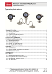
The pressure transmitter PASCAL CS21xx is intended for measuring the relative and
absolute pressure of gases, vapors and liquids as specified in the data sheet. For a correct
function the permissible overload pressure indicated on the type plate must not be
exceeded.
1.2
General Safety Notes
The installation, set up, service or removal of this device must only be done by trained,
qualified personnel using suitable equipment and authorized to do so by the plant
operator.
Improper installation or use of these devices or the use of damaged or defective
devices may result in severe injury or property damage!
1.3
CE Marking
The CE marking on these devices certifies their compliance with the applicable EU
Directives for placing products on the market within the European Union.
The following guideline applies to model series PASCAL CS21xx:
EMC Guideline
2
EMC 2004/108/EG
Transportation and Storage
Store and transport these devices only under clean, dry conditions. Avoid exposure to
shocks and excessive vibrations.
Permissible storage temperature: -40…85 °C
3
Installation and Commissioning
Before installing the device, be sure that the device is suitable for the intended process
application with respect to pressure range, resistance to overpressure, compatibility with
the monitored medium, thermal stability and pressure port fitting type. The used gaskets
must be compatible with the used process connection and resistant to the medium.
Complete the mechanical installation before making the electrical connections.
Before placing the device in service, check it carefully for leaks under pressure.
When checking the operation of the device, be sure to check the zero-point signal with
respect to the installed position. In the standard design, the transmitter is preset at the
factory for vertical installation. For pressure ranges of < 2 bar, changes in the installation
position will also cause the zero-point position to shift. This zero-point offset can be
subsequently corrected by making an appropriate adjustment (see 6.3.2).
BTA 060, Rev 1K1
Page 2/18