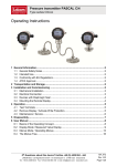
1
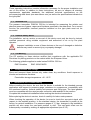
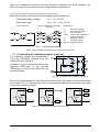
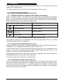
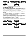
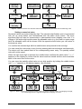
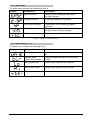
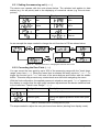
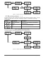
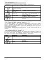
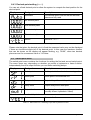
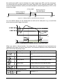
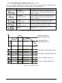
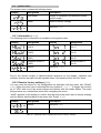
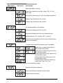
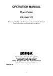
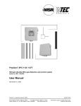
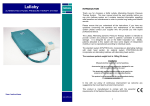
Operating Instructions for pressure transmitter
PASCAL CS, Type Series CS2100 and CS2110
Table of contents
1
General Information ..................................................................................................... 2
1.1
Intended Use ........................................................................................................ 2
1.2
General Safety Notes............................................................................................ 2
1.3
CE Marking ........................................................................................................... 2
2
Transportation and Storage ......................................................................................... 2
3
Installation and Commissioning ................................................................................... 2
3.1
Electrical Connection ............................................................................................ 3
3.2
Adjusting the display unit ...................................................................................... 4
3.3
Devices with flush mounted diaphragm ................................................................ 4
4
Operation ..................................................................................................................... 5
4.1
Setup / Parameterization ...................................................................................... 5
4.2
Maintenance ......................................................................................................... 5
5
Removal....................................................................................................................... 5
6
User Manual................................................................................................................. 6
6.1
System operating principles.................................................................................. 6
6.2
Main menu .......................................................................................................... 10
6.3
Basic menu (bASE) ............................................................................................. 10
6.4
Display menu (diSP) .......................................................................................... 13
6.5
Switch-point menu .............................................................................................. 14
6.6
System menu...................................................................................................... 17
6.7
Overview of the menu tree.................................................................................. 18
Do you have questions about this device? Call our hotline at: +49 (0) 4408 804-444
LABOM Mess- und Regeltechnik GmbH · Im Gewerbepark 13 · 27798 Hude · Germany
Tel.: +49 (0) 4408 804-0 · Fax: +49 (0) 4408 804-100 · e-mail: [email protected] · www.labom.com
BTA 060
Rev 1K1
Page 1/18
1
General Information
These operating instructions contain information necessary for the proper installation and
use of this device. In addition to these instructions, be sure to observe all statutory
requirements, applicable standards, the additional technical specifications on the
accompanying data sheet (see www.labom.com) as well as the specifications indicated on
the type plate.
1.1
Intended Use
The pressure transmitter PASCAL CS21xx is intended for measuring the relative and
absolute pressure of gases, vapors and liquids as specified in the data sheet. For a correct
function the permissible overload pressure indicated on the type plate must not be
exceeded.
1.2
General Safety Notes
The installation, set up, service or removal of this device must only be done by trained,
qualified personnel using suitable equipment and authorized to do so by the plant
operator.
Improper installation or use of these devices or the use of damaged or defective
devices may result in severe injury or property damage!
1.3
CE Marking
The CE marking on these devices certifies their compliance with the applicable EU
Directives for placing products on the market within the European Union.
The following guideline applies to model series PASCAL CS21xx:
EMC Guideline
2
EMC 2004/108/EG
Transportation and Storage
Store and transport these devices only under clean, dry conditions. Avoid exposure to
shocks and excessive vibrations.
Permissible storage temperature: -40…85 °C
3
Installation and Commissioning
Before installing the device, be sure that the device is suitable for the intended process
application with respect to pressure range, resistance to overpressure, compatibility with
the monitored medium, thermal stability and pressure port fitting type. The used gaskets
must be compatible with the used process connection and resistant to the medium.
Complete the mechanical installation before making the electrical connections.
Before placing the device in service, check it carefully for leaks under pressure.
When checking the operation of the device, be sure to check the zero-point signal with
respect to the installed position. In the standard design, the transmitter is preset at the
factory for vertical installation. For pressure ranges of < 2 bar, changes in the installation
position will also cause the zero-point position to shift. This zero-point offset can be
subsequently corrected by making an appropriate adjustment (see 6.3.2).
BTA 060, Rev 1K1
Page 2/18
After the mechanical installation and the electrical connection are both complete, the
device is ready for use as soon as the voltage supply is switched on.
3.1
Electrical Connection
Make all electrical connections with the voltage supply switched off.
Permissible supply voltage
UV = 14 - 30 VDC
Permissible load
RB = (UV - 14 V) / 22 mA
4-pole connector
8-pole connector (for switching
outputs)
Explanations
(+)
(-)
n.c.
S1/S2
plus-side of supply
minus-side of supply
not connected
common pin of switching
outputs (see below)
S1
switching output 1
S2
switching output 2
Pgm1/2 programming pins
Figure 1: Pin assignment for M12 circular connector (device side)
3.1.1 Connecting the switching outputs (optional)
The switching outputs are potential-free.
They are electrically isolated from the
supply side (see Figure 2).
Therefore you can connect the load on the
high-side (PNP-style) or the low-side
(NPN-style) as long as you use only one
switching output.
Figure 2: Switching outputs isolated from supply
Due to the limited number of pins either the low-side or the high-side is combined internally
and routed to Pin 5. Therefore you have to connect both loads as shown below if you want
to use both switching outputs.
4
2
S1
S2
RL
+
5
4
4
+
2
S1
S2
RL
-
RL1
+
2
S1
5
RL2
S2
5
Figure 3: Connecting options with shared low-side
BTA 060, Rev 1K1
Page 3/18
5
S1
RL
5
+
S2
S1
5
+
S2
S1
+
S2
RL1
2
2
-
RL
2
-
4
4
-
4
RL2
Figure 4: Connecting options with shared high-side
Use an appropriate free-wheeling diode, if you want to switch inductive loads.
The default values fort he switching units are as follows, if not specified otherwise:
switching unit 1
switching unit 2
output function
hysteresis, normally open
hysteresis, normally open
switch point
40% of measuring range
80% of measuring range
reset point
20% of measuring range
60% of measuring range
Table 1: Default settings for switching outputs
3.2
Adjusting the display unit
You can turn the display unit approx. 300° to optim ize
the readability. To do so hold the stainless steel
housing with one hand and turn the display unit with
the other hand into the wanted position.
The turning angle is limited by an internal limit stop. Do
not try to force the display unit beyond that point. It
might get destroyed.
3.3
Devices with flush mounted diaphragm
For type series CS2110 with flush mounted diaphragm observe the following hints:
Do not remove the protective cap or protective wrapping from the diaphragm before
immediate installation to prevent soiling or damage.
Do not touch the diaphragm as this might cause deformation or damage. Any deformation
may negatively influence the zero point or other characteristics of the device.
If required you can find further information about diaphragm seals in the separate
operating instructions BTA-062.
BTA 060, Rev 1K1
Page 4/18
4
Operation
During device operation, take care that the device remains within its intended temperature
range, that its maximum operating pressure is not exceeded and that it is not harmed by
the medium to which it is exposed. No other monitoring is necessary.
Permissible ambient temperature: -20 °C to +85 °C
Permissible overload pressure: See type plate (depends on pressure range)
The measured value is shown on the four-digit display. The LEDs above the display
indicate the switch states of the switching outputs. The LEDs are on, when the switch is
active.
4.1
Setup / Parameterization
You can set or change all adjustable parameters of the device at the device itself. This is
described in detail in the user manual (see below).
The three buttons on the display module are capacitive, not mechanical, therefore they do
not move when pressed. Capacitive buttons sense the presence of your finger when
pressed. Withdraw the finger at least one centimeter after pressing a button. This helps
the device to clearly detect individual keypresses.
If the device comes with an 8-pole connector, you can also configure it with a
communication modem and the PC-Software COMLINE.S. This is described in a separate
manual.
4.2
Maintenance
When properly installed in accordance with applicable specifications, this device is
maintenance-free. However, we recommend an annual recalibration of the device.
The device contains no user-serviceable or user-replaceable parts or components.
5
Removal
Before attempting to remove the device, be sure to first relieve the process system
pressure. Shut off the pressure source for all feed lines and relieve the pressure in them.
Attempting to remove the device from a still-pressurized system may result in
severe injury.
Be sure to de-energize the power supply to the device before disconnecting the electrical
connections. Once this is done, the device may be mechanically removed.
Be sure that residue in the process system and in the device itself do not present a danger
to humans or the environment. During dismantling and removal, the device must be easy
to remove from the process system. Do not apply any force during removal work. After the
device has been removed, seal off the measuring point and mark the open process
accordingly.
Removed devices may contain hazardous deposits and residue. When removing
or transporting these devices, be sure to take appropriate safety precautions.
BTA 060, Rev 1K1
Page 5/18
6
User Manual
This chapter describes the handling and parameterization of the device with the three
buttons on the display head.
You find an overview of the menu tree on the last page of this document.
6.1
System operating principles
6.1.1 System feedback to operator when buttons are pressed
When you press a button, the switching output LEDs flash acknowledging the pressed
button. The left and right arrow buttons are indicated by flashing the left or the right LED.
When you press the left and right arrow buttons at the same time, both LEDs will flash.
Both LEDs flash rapidly if you press the middle button.
Button
Feedback
Left arrow button
Left LED flashes
Right arrow button
Right LED flashes
Both arrow buttons at the
Both LEDs flash
same time
Middle button
Both LEDs flash rapidly
Table 2: Feedback to operator when buttons are pressed
The switching outputs are not affected by the LED flashing. When there is no button
pressed, the output states are displayed.
6.1.2 Display mode / Measured-value screen
When the device is switched on, it goes into display mode. The currently measured value
is displayed, or it is displayed alternately with the unit (see 6.4.1).
If the measured value is greater than the maximum number that can be displayed by the
system – this can be caused by setting a fixed decimal point (see Sec. 6.4.3) –, the
maximum number that can be displayed will flash.
By pressing the middle button, the selected unit will be displayed. The unit will continue to
be displayed as long as the middle button is pressed.
The arrow buttons have no function in display mode.
6.1.3 Activating the Menu mode / Key lock
A key lock prevents an unintentional misconfiguration of the device. You have to press
both arrow buttons simultaneously for at least two seconds to enter the operator menu.
The first entry of the main menu (bASE) will then appear on the display. If you hold both
buttons for more than four seconds, the device switches back to display mode and shows
the currently measured value again.
BTA 060, Rev 1K1
Page 6/18
Figure 5: Button functions in display mode, with example
6.1.4 Menu mode / Operator menu
When you enter the menu mode, you always begin with the first main menu item (bASE).In
menu mode you can navigate the menu with the arrow buttons. The middle button selects
the menu item resp. enters the submenu. If a value is just displayed (e.g. the maximum
pointer) you can also return back to the menu item with the middle button.
The menu item "-ret-" (return), which allows you to go back to the next highest menu
level, is available in every menu. When you are in the main menu, "-rEt-" returns you to
display mode.
At the end of a menu (typically, the "-rEt-" item) you return to the first menu item by
repressing the down arrow button again. Similarly, you can jump from the first menu item
to the end of the menu or a value list with the up arrow button.
You can return to the next higher menu level from every menu item by pressing both arrow
buttons at the same time. The return is indicated by a blinking "-rEt-". By pressing both
buttons for more than one second, you return to the display mode. Cancelling the menu
mode is indicated in the display by a blinking "-ESc-" (escape).
If no button is pressed for five minutes in menu mode, the device automatically switches
back to display mode.
previous
menu item
measured
value
>1s
upper menu
menu
item
sub menu
next menu
item
Figure 6: Button functions in menu mode
BTA 060, Rev 1K1
Page 7/18
An example of button functions available in menu mode is shown below.
Figure 7: Button functions in menu mode (example)
For the sake of simplicity, the return to the next higher menu and directly to display mode
will not be shown anymore.
6.1.5 Setting values
There are two types of values that can be altered:
− values that can be selected from a predefined parameter list
− numerical values
Selecting a value from a parameter list
Parameter lists – for example, the units list – behave like a menu. You can scroll through
the list in both directions with the arrow buttons. Each list contains the "-rEt-" item, which
allows you to return to the next higher menu level.
The middle button stores your selection. "Stor" appears on the display to confirm that the
value has been stored, and the device returns to the higher level menu item.
You can cancel the selection by pressing both arrow buttons at the same time. The device
will then switch back to the corresponding menu entry. The selected value will not be
saved.
The figure below depicts the button functions in a parameter list. E.g. if you are in the
parameter list for the unit, you can scroll thru the available units with the arrow buttons.
With the middle button you store the displayed unit. "Stor" appears on the display to
confirm that the changed unit has been stored and the device switches back to the menu
item for selecting the measuring unit (unit).
BTA 060, Rev 1K1
Page 8/18
previous
list entry
menu item of
parameter list
list entry
next
list entry
Figure 8: Button functions in a selection menu and example with parameter list for measuring units
Setting a numerical value
Numerical values are entered digit by digit. The selected digit flashes and is incremented
with the up arrow button and decremented with the down arrow button. The more
significant digit will also be incremented or decremented when stepping over zero. If a
change of the active digit would exceed the allowable value (e.g. the lower or upper range
limit) the allowable value will be shown. With the opposite arrow button you can return to
the previous value.
You confirm the selected digit with the middle button and proceed to the next digit.
You can cancel the value entry at any time by pressing both arrow buttons simultaneously.
The device will then switch back to the corresponding menu entry. The partially edited
value will not be saved.
When the right-most digit is selected, the middle button confirms the whole value. "Stor"
appears on the display to confirm that the value has been stored and the device switches
back to the menu item for the value.
You can store the partially edited value at any digit position by holding the middle button
until "Stor" appears on the display (approx. two seconds).
menu item
for value
c)
a)
>2s
b)
Figure 9: Button functions for entering numeric values a) limit to allowed values, b) changing one digit,
c) incrementing the more significant digit when stepping over zero
BTA 060, Rev 1K1
Page 9/18
6.2
Main menu
The main menu contains the following functions:
Display
Designation
Description
Basic functions
Setting the unit, setting the zero point,
min./max. pointer
Display functions
All settings relating to the display
Switch point settings
Configuration of the switching outputs
(optional)
System data
Displaying system data (versions, serial
number); reset to factory settings
Return
Return to display mode
Table 3: The items in the main menu
6.3
Basic menu (bASE)
The basic menu contains the following items:
Display
Designation
Description
Measuring unit
Setting the measuring unit via a parameter
list
Set zero point
(Teach lower range)
Setting the applied pressure as zero point
(0 bar)
Min. pointer (low)
Display resp. delete the min. pointer
Max. pointer (high)
Display resp. delete the max. pointer
Return
Return to the main menu
Table 4: The items in the basic menu
BTA 060, Rev 1K1
Page 10/18
6.3.1 Setting the measuring unit (unit)
The device can operate with the units shown below. The selected unit applies to data
entries (e.g. for set points) and to the displaying of numerical values (e.g. the min./max.
pointer).
Display
Unit
Display
Unit
bar
kPa
mbar
MPa
PSI
mA
%
Return
Table 5: Parameter list for the measuring unit
As an example the steps needed to change the unit from bar to PSI are shown below.
Figure 10: Operator actions for changing the unit from bar to PSI
6.3.2 Correcting the Zero Point (tlr)
You can correct the zero point by up to 20% of the measuring range with the "teach lower
range" menu item (tlr). When the menu item is selected the entry points to "-rEt-". To
trigger the function go to "YES" with one of the arrow buttons and confirm with the middle
button. This extra step prevents any unintentional zero shift while navigating the menu.
With the final confirmation, the applied pressure is stored as zero point. "donE" appears on
the display to confirm that the zero point has been adjusted and the device switches back
to the menu item "Teach Lower Range" " (tlr).
Display
Designation
Description
Return
Return to "tlr"
Confirm (yes)
Setting the applied pressure as the zero point
(0 bar)
Table 6: Parameter list for correcting the zero point
The steps needed to adjust the zero point are shown below (starting from display mode).
BTA 060, Rev 1K1
Page 11/18
Figure 11: Operator actions for correcting the zero point
6.3.3 Min. and max. pointers ( Lo / Hi )
The device has min./max. pointers for minimum and maximum pressure values. You can
display and reset them in this menu. Resetting a pointer is confirmed by showing "----"
on the display.
Display
Designation
Description
Value of min./max
pointer
Value of min./max. pointer in the selected
measuring unit
Clear
Reset the stored pointer value
Return
Return to "Lo" or "Hi"
Table 7: Parameter list for min./max. pointer
The steps needed to reset the minimum pointer are shown below.
>2s
>1s
Figure 12: Operator actions to reset the minimum pointer
BTA 060, Rev 1K1
Page 12/18
6.4
Display menu (diSP)
The display menu for configuring the display contains the following items:
Display
Designation
Description
Display period for
measured value (time
data)
Can be set between 0.5 and 99.9 s
Display period for unit
(time unit)
Can be set between 0.0 and 99.9 s
Rotate 180°
Rotate screen by 180° when the device i s
installed upside down
Decimal places
Setting the decimal places (zero to three
fixed decimal places or automatic)
Return
Return to "diSP"
Table 8: The items in the display menu
6.4.1 Display period for measured value/unit (td / tu)
The unit can be displayed in two ways, either by pressing the middle button in display
mode or alternately with the measured value. When displayed alternately with the
measured value the display periods for the measured value and the unit can be selected
independently of one another.
If the period for displaying the unit is set to zero, only the measured value will be
displayed.
6.4.2 Rotating the display by 180° ( rot)
You can rotate the 7-segment display by 180°, so th at it can be read when the device is
put in place upside down. The function for the arrow buttons are also swapped in this
case, so that the device can be operated the same way in either position.
Display
Designation
Description
Standard (0°)
Upside down (180°)
Display rotated 180° for upside down
operation
Return
Return to "rot"
Table 9: Parameter list for rotating the display
BTA 060, Rev 1K1
Page 13/18
6.4.3 Decimal-point setting (decP)
You can set a fixed decimal point or allow the system to compute the best position for the
decimal point.
Display
Designation
Description
Automatic
The decimal point is set so that the decimal
places are fully used
No decimal place
One decimal place
Two decimal places
Three decimal places
Return
Return to "dEcP "
Table 10: Parameter list for setting the decimal point
Please note that when the decimal point is fixed the measured value may not be displayed
if there are insufficient digits left of the decimal point. In this case the maximum number
that can be shown on the display will appear flashing, e.g. "99.99", when two decimal
places are set for a measured value of 110 mbar.
6.5
Switch-point menu
The switch-point menu contains the functions for setting the first and second switch-point.
The menu items vary, depending on whether you select a hysteresis or frame function.
Independently from the output function you can define switching delays.
Display
Designation
Description
Switch-point
Switch-point in the selected measuring unit
Reset-point
Reset-point in the selected unit
Delay switch
Output delay at the switch point
Delay reset
Output delay at the reset point
Output function
Configuring the output (normally open /
normally closed, hysteresis / frame)
Menu items for second switch point
Return
Return to "SP"
Table 11: Menu items for a switching output with hysteresis function
BTA 060, Rev 1K1
Page 14/18
The switch-point (SP) must be between the upper range limit (URL) and the reset-point.
The reset-point (rP) must be between the lower range limit (LRL) and the switch-point. The
minimum distance between switch-point and reset-point (minimal hysteresis) is 0.5% of the
measuring range.
0.5% of MR
Setting range for
the reset-point
LRL
rP
Setting range for
the switch-point
SP
URL
Figure 13: Setting ranges for switch-point and reset-point
You can define delays for the switch-point as well as the reset-point, e.g. to avoid that
short pressure peaks trigger the switch.
Figure 14: Output delays for a hysteresis function normally open (Hno)
When you select a frame function, the menu items for switch-point and reset-point are
replaced by the upper and lower frame limits. The minimum difference of the frame limits is
also 0.5% of the measuring range.
Display
Designation
Description
Frame high
Upper frame limit in the selected measuring
unit
Frame low
Lower frame limit in the selected measuring
unit
Delay switch
Output delay when entering the frame
Delay reset
Output delay when leaving the frame
Output function
Configuring the output (normally open /
normally closed, hysteresis / frame)
Menu items for second switch point
Return
Return to "SP"
Table 12: Menu items for a switching output with frame function
BTA 060, Rev 1K1
Page 15/18
6.5.1 Configuring the output function (out 1/2)
You can choose a hysteresis or frame function as the output function. Furthermore you
can define whether the output is normally open or normally closed.
Display
Designation
Description
Hysteresis,
normally open
If the pressure is above the switch-point the
switch is closed. At the lower range limit the
switch is open.
Hysteresis,
normally closed
If the pressure is above the switch-point the
switch is open. At the lower range limit the
switch is closed.
Frame,
normally open
Inside of the frame the switch is closed. At
the lower range limit the switch is open.
Frame,
normally closed
Inside of the frame the switch is open. At the
lower range limit the switch is closed.
Return
Return to "out 1" or "out 2"
Table 13: Parameter list for output function
switch-point (SP) or
upper frame limit (FH)
reset-point (RP) or
lower frame limit (FL)
Hysteresis / normally open (Hno)
Hysteresis / normally closed (Hnc)
Frame / normally open (Fno)
Frame / normally closed (Fnc)
Figure 15: The output functions
BTA 060, Rev 1K1
Page 16/18
6.6
System menu
The system menu contains the following items.
Display
Designation
Description
Information
Display of Hardware and software version,
serial number
Reset
Reset to factory settings
Return
Return to "SYS"
Table 14: The items in the system menu
6.6.1 Information (inFo)
The following device information is available in the system menu.
Display
Designation
Display
Designation
Hardware version 1
(HW1)
Serial number 1
(Sn 1)
Hardware version 2
(HW2)
Serial number 2
(Sn 2)
Software version 1
(SW1)
Serial number 3
(Sn 3)
Software version 2
(SW2)
Serial number 4
(Sn 4)
Return
Return to "inFo"
Table 15: Menu items in the information menu
Due to the limited number of alphanumerical segments on the display, hardware and
software versions are split into two separate items, and serial number into four items.
6.6.2 Reset to factory settings (rES)
You can reset the device to the configuration as delivered with the menu item "Reset"
(rES). When the menu item is selected the entry points to "-rEt-". To trigger the function
go to "YES" with one of the arrow buttons and confirm with the middle button. This extra
step prevents any unintentional reset while navigating the menu.
"donE" appears on the display to confirm that the device has been reset to factory settings
and the device switches back to the menu item "Reset" (rES).
Display
Designation
Description
Return
Return to "rES"
Confirm (yes)
Resetting the device to factory settings
Table 16: Parameter list for resetting the device to factory settings
BTA 060, Rev 1K1
Page 17/18
6.7
Overview of the menu tree
Main menu
Sub menu
Description
Menu with basic functions
Setting the measuring unit (bar, mbar, PSI, %, kPa,
MPa, mA)
Setting the lower range (4 mA) to the applied pressure
Display resp. delete the min. pointer
Display resp. delete the max. pointer
All settings relating to the display
Setting the display period for the unit
Setting the display period for the measured value
Display direction (0° = normal, 180° = turned)
Setting the decimal places (zero to three fixed decimal
places or automatic)
Configuring the switching outputs (only if available)
Switch-point or upper frame limit of
the first switching output
Reset-point or lower frame limit of the
first switching output
Output delay at the switch point of the
first switching output
Output delay at the reset point of the
first switching output
Output function of the first switching
output (Hno, Hnc, Fno, Fnc)
Menu items for the second switching output
System information and reset
Hard- and software versions, serial number
Reset to factory settings
BTA 060, Rev 1K1
Page 18/18