1
Installation/User Manual
y Make sure to read the cautions for safety before installation and use, and
use it correctly.
y It is intended to keep protect the safety of the installer and user and to
prevent the property damage, etc.
y After reading the user manual, please keep it at a place where user can
access any time.
.PEFM/BNF: BACnet Gateway (ACP BACnet)
.PEFM/P: PQNFB17C1, PQNFB17C0
*MFL67709501
P/NO : MFL67709501
www.lge.com
Explanatory Notes
i
Explanatory Notes
The contents of this ACP BACnet User Guide are protected by international copyright laws, and the
Computer Program Protection Act. The contents of the User Guide and the programs mentioned
herein may only be used under license from LG Electronics in strict adherence to the user
agreement.
You may not reproduce or distribute, by any means, copies of this User Guide, or any part of it,
without prior approval from LG Electronics.
Copyright © 2013 LG Electronics. All rights reserved. Twin Towers 20, Yeouido,
Yeongdeungpo-gu, Seoul
Registered Trademarks
ACP BACnet is a registered trademark of LG Electronics. All other products and company names are
trademarks of their respective owners and are used for illustrative purposes only.
ENGLISH
Copyrights
ii
Explanatory Notes
ENGLISH
TIPS FOR SAVING ENERGY
Here are some tips that will help you minimize the power consumption when you use the air
conditioner. You can use your air conditioner more efficiently by referring to the instructions below:
Do not cool excessively indoors. This may be harmful for your health and may consume more
electricity.
Block sunlight with blinds or curtains while you are operating the air conditioner.
Keep doors or windows closed tightly while you are operating the air conditioner.
Adjust the direction of the air flow vertically or horizontally to circulate indoor air.
Speed up the fan to cool or warm indoor air quickly, in a short period of time.
Open windows regularly for ventilation as the indoor air quality may deteriorate if the air
conditioner is used for many hours.
Clean the air filter once every 2 weeks. Dust and impurities collected in the air filter may block
the air flow or weaken the cooling / dehumidifying functions.
Notes
The product images and descriptions included in this manual are stated based on ACP BACnet
Free volt (Model No.: PQNFB17C0).
y ACP BACnet Free volt (PQNFB17C0)
y ACP BACnet 24V (PQNFB17C1)
For your records
Staple your receipt to this page in case you need it to prove the date of purchase or for warranty
purposes. Write the model number and the serial number here:
Model number :
Serial number :
You can find them on a label on the side of each unit.
Dealer’s name :
Date of purchase :
ENGLISH
TIPS FOR SAVING ENERGY
iii
ENGLISH
MEMO
IMPORTANT SAFETY INSTRUCTIONS
READ ALL INSTRUCTIONS BEFORE USING THE APPLIANCE.
Always comply with the following precautions to avoid dangerous situations and ensure peak
performance of your product
WARNING
It can result in serious injury or death when the directions are ignored.
CAUTION
It can result in minor injury or product damage when the directions are ignored.
WARNING
y Installation or repairs made by unqualified persons can result in hazards to you and others.
y Installation MUST conform with local building codes or, in the absence of local codes, with the
Nation Electrical Code NFPA 70/ANSI C1-1003 or current edition and Canadian Electrical Code
Part1 CSA C.22.1.
y The information contained in the manual is intended for use by a qualified service technician
familiar with safety procedures and equipped with the proper tools and test instruments.
y Failure to carefully read and follow all instructions in this manual can result in equipment
malfunction, property damage, personal injury and/or death.
Installation
y Any question about the product installation should be asked to the service center or the
professional installation agency.
- It may cause fire, electric shock, explosion or injury.
y Consult the service center or the professional installation agency about reinstalling the installed
product.
- It may cause fire, electric shock, explosion or injury.
y Please use the standardized parts.
- It may cause fire, electric shock, explosion, injury, or failure.
y Do not keep or use combustible gas or inflammable material near the product.
- IT may cause fire or electric shock.
y Do not disassemble, repair or modify the product at random.
- It may cause failure of the product.
ENGLISH
IMPORTANT SAFETY INSTRUCTIONS
v
vi
IMPORTANT SAFETY INSTRUCTIONS
y Do not install where raindrop can fall.
- It may cause failure of the product.
ENGLISH
y Do not install the product at wet place.
- It may cause failure of the product.
y Provided product and adaptor shall only be installed and used inside a building.
- It may cause fire or failure of the product.
*Do not install or use outside.
y Install stably in a place that can endure the weight of the ACP BACnet.
- If the installation place is not strong enough, the ACP BACnet may fall and damaged.
y Make sure to enquire to the specialty store of the product purchase or service center for
electric works.
- It may cause fire or electric shock.
y Do not damage the power cord or bend it by force.
- It may cause fire or electric shock.
y You need to use a safely insulated power supply which follows IEC61558-2-6 and NEC Class2
- If you do not follow, It may cause fire, electric shock, explosion or injury.
y Do not connetion 220V power to 24V products
- If you do not follow, It may cause fire, electric shock, explosion or injury.
y Do not connect power cord to the control signal connector.
- It may cause fire or explosion.
Operation
y Do not change or extend the power cord with your own discretion.
- It may cause fire or electric shock
y Do not place any heating device near the product.
- It may cause fire.
y Do not use any heating device near the power cord.
- It may cause fire or electric shock.
y Do not let water flow into the product.
- It may cause electric shock or failure.
y Do not put heavy weight on the power cord.
- It may cause fire or electric shock.
y Do not put heavy weight on the product.
- It may cause the failure of the product.
IMPORTANT SAFETY INSTRUCTIONS
vii
y If the product is flooded, consult the service center or the professional installation agency.
y Let the children or the old and the weak be controlled by the guardian to use.
- It may cause accident or failure.
y Do not give any shock to the product.
- Any shock to the product may cause failure.
y Grab the head of the plug of the power cord to pull when disconnecting the plug, and do not
click the plug with wet hands.
- It may cause fire or to deform the product.
y Do not use the product in certain environments as follows.
- If the product is used in a place with oil, steam, or sulfuric acid gas, performance may be
degraded or product may be damaged.
y Do not press the switch or button with sharp objects.
- It may cause electric shock or failure of the product.
y Please check the operation temperature.
- If the product is used in an environment with the temperature exceeding the operation boundary, it may cause a severe damage.
Please check the usage temperature boundary in the manual. If there is no specified temperature, please use the product within the boundary of 0~40°C.
y Do not put a container, etc. with water on the product.
- It may cause fire or electric shock.
y Do not click the switch with wet hand.
- It may cause electric shock or failure of the product.
y Please read installation and user manual for connection with PC or peripheral devices.
- It may cause fire or failure of the product.
y If a warning window appears on PC, product stops, or it does not work, immediately stop the
usage.
- It may cause fire or failure of the product.
CAUTION
Operation
y Do not use strong detergent such as solvent, but a soft cloth.
- It may cause fire or to deform the product.
y Please check the rated capacity of the power.
- It may cause fire or failure of the product.
ENGLISH
- It may cause fire or electric shock.
ENGLISH
MEMO
Table Of Contents
ix
Table Of Contents
ENGLISH
1
1
3
ACP BACnet
FUNCTIONS AND
SPECIFICATION
ACP BACnet Functions
ACP BACnet Components
97
97
Installing ACP BACnet
Installing ACP BACnet
98
Check points during the ACP
BACnet installation
99
Setting the indoor unit address
4
Names of each part of ACP
BACnet
101
Setting the PI485 and connecting
the cable
6
ACP BACnet Hardware
Specification
103
Installing ACP BACnet and
connecting cables
108
Setting the ACP BACnet network
address
117
Setting the functions of the ACP
BACnet
7
7
9
11
11
38
Starting
Login and logout
Home screen composition and
features
Control/Monitor
Schedule
Auto Logic
70
Report
72
80
Agreement
Using the Program
45
67
133 LG's ACP BACnet
Statistics
Installing
Environment
135 Functional Specifications
ACP BACnet
191
191
195
196
205
NOTES
Troubleshooting
Guide to Open Source Software
BIBBs
ACP-BACnet Error Response Table
ver 1.0.0
ENGLISH
MEMO
ACP BACnet FUNCTIONS AND SPECIFICATION
ACP BACnet is the central controller that can manage up to 256 equipments in one space
individually or as combined. ACP BACnet can monitor or control the equipments installed in
each room of the building from the places such as the management office of a building or the
administration office of a school.
ACP BACnet Functions
Major functions of the ACP BACnet are as follows.
Environment setting function using the ACP BACnet external buttons ACP BACnet can use the
external buttons installed outside of the ACP BACnet to set the following functions.
Set Network environment (IP address, Net mask, Gateway)
Set the function to use between Peak/demand function
SW upgrade function
Data backup function
Data recovery function
Set the ID of ACP BACnet when connected with demand function
Fire Alarm function
Fahrenheit/Celsius setting function
Device ID setting function
Vnet number setting function
Foreign Device register function
PQNFB17C0
PQNFB17C0
ENGLISH
ACP BACnet FUNCTIONS AND
SPECIFICATION
1
2
ACP BACnet FUNCTIONS AND SPECIFICATION
Embedded web server function
ENGLISH
window using Internet Explorer, the central control program in ACP BACnet web server is
automatically run, and the functions of various contents can be used.
Internet
wxjwjYYhW
Internet
Explorer
Controlling of up to 256 air conditioner indoor units
Monitoring of error and operation status
Controlling the peak power / demand power
System setting function
Devices that can interface with ACP BACnet
Device
ACP BACnet
AC Ez
o
Simple Central Controller
o
AC-Smart
o
AC Manager
o
Air Conditioner
o
Ventilation
o
AWHP
o
Fire Alarm
o
Chiller
x
AHU
o
ACP BACnet FUNCTIONS AND SPECIFICATION
3
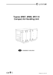
ACP BACnet Components
Open the packaged box of the ACP BACnet, and check if all of the corresponding components are
included.
Quick manual
y Make sure to read the cautions for safety before installation and use, and
use it correctly.
y It is intended to keep protect the safety of the installer and user and to
prevent the property damage, etc.
y After reading the user manual, please keep it at a place where user can
access any time.
.PEFM/BNF: BACnet Gateway (ACP BACnet)
.PEFM/P: PQNFB17C1, PQNFB17C0
P/NO : MFL67709511
ACP BACnet
Power Supply Adaptor
Input: 100~240V
AC 50/60Hz 3.33A
Output: DC 12V
3.33A, 40W MAX
www.lge.com
ACP BACnet Quick Manual
Power Cord
250V AC, 3A
ACP BACnet Installation/User
Manual CD
Notes
Power Supply Adaptor and Power Cord are not included in PQNFB17C1.
ENGLISH
Inside the packaged box of the ACP BACnet, there are the components as in the following drawing.
4
ACP BACnet FUNCTIONS AND SPECIFICATION
Names of each part of ACP BACnet
ENGLISH
ACP BACnet is composed as follows.
¢
PQNFB17C0
£
¤
¥
¦
§
PQNFB17C0
¨
©
ª
«
¬
ACP BACnet FUNCTIONS AND SPECIFICATION
5
Notes
Number
Item
Description
£
Cover
Front cover of the ACP BACnet
¤
RS-232 console port
Reserved communication port
¥
Adaptor connection
jack
Jack for DC 12V to connect to the power supply adaptor
(not supported by PQNFB17C0.)
¦
Power port
AC24V port for power connection (not supported by
PQNFB17C0)
§
Buttons and LCD
Buttons and LCD to set network environment and to
display other information
¨
Optional input/
output and RS-485
communication port
Connection port to connect to external input/output signals
and RS-485 communication port for external expansion.
(8 DI’s, 2 DO’s, 2 RS-485 communication ports)
©
RS-485 communication
port
RS-485 communication ports to connect to air conditioner
and ventilation equipment (4 in total)
ª
Mini USB port
USB to Serial port for software debugging
«
USB port
¬
SD card slot
For RS-485 communication data backup.
Ethernet port
Ethernet port to connect to internet and AC Manager
®
Power switch
Switch to turn on or off the power of the ACP BACnet
For software update and data backup
Caution
If four times the power connector for the connection, as shown by using the right connection, but
please note that an electric shock.
Use the designated parts must be connected to a power source.
y Connector manufacturers: PHOENIX CONTACT
PartNo: MVSTBR 2,5 / 2-ST-5, 08 2P 5.00MM
ENGLISH
No. 3 and No. 4 may be different for each model.
6
ACP BACnet FUNCTIONS AND SPECIFICATION
ACP BACnet Hardware Specification
ENGLISH
ACP BACnet hardware specification is as follows.
Category
Boundary of usage temperature
CPU
Description
0°C~40°C
i.MX515
y 32Bit 800MHz speed
RAM
128MB DDR2 SDRAM * 2EA
ROM
4GB i-NAND Flash
Communication ports
External input/output ports
y Ethernet 10 / 100 BASE-T
y USB : USB Host (SW upgrade, data backup)
mini USB Device (Debug)
y RS-485 communication ports 6EA
y SD card slot (RS-485 communication logging)
y RS-232 Console Port (HMI)
DI, DO
LED
27EA (RS communication status, Ethernet communication
status, power status, operation status)
LCD
20 ×4 Character-LCD (network environment setting and
information display)
Notes
License policy
This product follows GPL (General Public License) for the use of Embedded Linux.
Starting
Login and logout
The following explains how to log in/out ACP BACnet.
Connected to the ACP BACnet
How to Connect to the ACP BACnet is as follows.
1.
Connected to theACP BACnet enter the IP address of the ACP BACnet in the Internet Browser.
Login
You can login as follows.
1.
2.
Run ACP BACnet.
After entering your ID and password in the login window, click [Confirm].
You are now logged in.
ENGLISH
Starting
7
8
Starting
Logout
ENGLISH
You can logout as follows.
1.
On the top right of the ACP BACnet screen, click the [Logout] button.
You are now logged out.
Starting
9
Home screen composition and features
ENGLISH
The following explains the home screen composition and features.
£
ⴘ
¤
¥
¦
§
¨
Number
Item
£
Running Status
(Unit)
¤
Time
¥
Today's Schedule
¦
Main Menu
§
Home
¨
View Menu
©
Current Menu
Description
Checks if all the devices are operating, has stopped, or
has already been checked.
Check the current date and time.
(You need Internet connection to check the weather.)
y Check the registered schedules in chronological order.
y Click the [+] button to move to the schedule menu.
Use ACP BACnet main menu.
Return to the home screen.
Display the active menu.
Display the name of the active menu.
ENGLISH
MEMO
Using the Program
11
Using the Program
ENGLISH
The following explains how to use the ACP BACnet functions.
Control/Monitor
Control/Monitoring is managing multiple devices collectively as one. The following explains the
Control/Monitor menu options.
Control/Monitoring screen composition and features
The following explains Control/Monitoring screen composition and features.
¢
¦
Number
Item
£
Select/Deselect All
¤
[Drawing] Button
¥
[Filter] Button
¦
§
View Type
Select
Group List
£
¤
§
¥
¨
Description
Select/deselect all devices in a group.
View floor plans of a group.
Select device types for which you want to check the
control status.
Select a view type for the monitoring screen
(Icon/Simple/Detailed)
(For more on View Type, refer to page 12)
Check device group listings.
12
Using the Program
ENGLISH
Number
Item
¨
Monitoring Screen
©
Device Control Box
Description
Check the control status of a device.
y Display the device control menu.
y The device control box shows different menus
depending on the device.
(For more on Control Menu per Device on page 17)
View Type
Control/Monitor menu has three types of views (icon, simple, and detailed). The following shows the
screen composition and features per view type.
Icon
The control status is shown in icons. The device icon has a composition and feature as follows.
¢
£
¤
¥
¦
§
Number
Item
£
Operation Mode and
Device Status Icon
¤
Device Icon
¥
Current Temperature
Description
The color at the top of the icon box shows the current
operation mode, and the status of the device is
indicated as an icon.
The device to be controlled is indicated as an icon.
The device shown may not represent the appearance
of the actual unit.
Display the current temperature.
¦
Operation Mode
§
Desired Temperature
Display the desired temperature.
¨
Device Name
Display the name of the device.
Display the operation mode of the device.
Using the Program
13
Simple
¢
£
Number
Item
Description
£
Operation Mode
The color of the box indicates the current operation
mode.
¤
Device Icon
The device to be controlled is indicated as an icon.
Details
All properties of the control device are tabulated in details.
ENGLISH
The control device and operation mode are displayed only.
14
Using the Program
Monitoring screen colors and icons
ENGLISH
Box colors and operation mode per icon
Color
Icon
Operation Mode
Cooling
Ventilation, General
(Blue)
Heating
Ventilation, Electric Heat
(Orange)
Dehumidification
(Navy)
Fan
(Sky Blue)
Power Saving
(Green)
Auto
Ventilation, Auto
(Purple)
-
ON & Short
-
OFF & Open
-
Error
(Yellow)
(Gray)
Using the Program
15
Device status icon
Device Status
Filter Exchange
Full Lock On
Peak/Demand Control
Schedule
Control device icon
Icon
Device Type
Indoor Device
Ventilators
AHU
AWHP
Chiller
DI
DO
DOKIT
ENGLISH
Icon
16
Using the Program
Device Control
ENGLISH
You can control the devices as follows.
1.
2.
From the main menu, click the [Control/Monitor] menu icon.
Click the device group you want to control from the group list.
The monitoring screen for the device is displayed.
3.
Click the device you want to control.
To select all devices, click the
button at the top.
The device control area appears at the bottom of the screen.
4.
In the device control box, set the control status of the device.
The device control box shows a different menu depending on the device. For information
about the control area for each device, GoTo the refer to Control Menu per Device on page 17.
5.
Once you have finalized the settings, click the [Apply] button.
Using the Program
17
Control Menu per Device
per device.
Indoor Device
The following is the indoor unit control menu and features.
Item
Operation
Description
y [ON] Button: Starts the operation of the device.
y [Off] Button: Stops the operation of the device.
GoTo
[Schedule] Button: Move to Schedule menu.
Room
Display the current temperature.
Set Temperature
Click >Ÿ@/>ź@ to set the temperature.
(The maximum/minimum temperatures that can be set may differ depending
on the model.)
Mode
y [COOL] Button: Operates with Cooling Mode.
y [HEAT] Button: Operates with Heating Mode.
y [AUTO] Button: Evaluates the operating environment conditions and
automatically sets the optimum temperature.
y [DRY] Button: Dehumidifies during rainy seasons or whenever humidity
is high. You cannot set the temperature in this mode.
y [FAN] Button: Purifies the air. You cannot set the temperature in this
mode.
Fan Speed
Swing
[Detail.] Button
y
y
y
y
[LOW] Button: Slow fan speed.
[MED] Button: Medium fan speed.
[HIGH] Button: Fast fan speed.
[AUTO] Button: Loops from LOW to MEDIUM to HIGH speeds.
y [Set] Button: Turns on automatic oscillation for the fan.
y [Clear] Button: Turns off automatic oscillation for the fan.
Controls details.
ENGLISH
The control box menu differs depending on the device. The following shows the control box menu
18
Using the Program
Indoor unit fine control
ENGLISH
Item
Operation
Set
Mode
Fan Speed
Swing
Filter Alarm
Description
y [ON] Button: Starts the operation of the device.
y [Off] Button: Stops the operation of the device.
Click >Ÿ@/>ź@ to set the temperature.
y [COOL] Button: Operates with Cooling Mode.
y [HEAT] Button: Operates with Heating Mode.
y [AUTO] Button: Evaluates the operating environment conditions and
automatically sets the optimum temperature.
y [DRY] Button: Dehumidifies during rainy seasons or whenever humidity is
high. You cannot set the temperature in this mode.
y [FAN] Button: Purifies the air. You cannot set the temperature in this
mode.
y
y
y
y
[LOW] Button: Slow fan speed.
[MED] Button: Medium fan speed.
[HIGH] Button: Fast fan speed.
[AUTO] Button: Loops from LOW to MEDIUM to HIGH speeds.
y [Set] Button: Turns on automatic oscillation of the fan.
y [Clear] Button: Turns off automatic oscillation of the fan.
Click the Disable button to deactivate the filter exchange alarm.
(For other models, it may not work properly.)
Using the Program
Item
Set Temp Range
[2Setpoint]
Button
Description
y
y
y
y
y
y
y
y
[HardLock] Button: Disables remote control for all features.
[Clear] Button: All functions are unlocked.
[ModeLock] Button: Disables remote control for local mode setting.
[Clear] Button: Mode is unlocked.
[FanLock] Button: Disables remote control for local fan speed setting.
[Clear] Button: Fan speed is unlocked.
[TempLock] Button: Disables remote control for local temperature setting.
[Clear] Button: Temperature setting is unlocked.
Click >Ÿ@/>ź@ to set the temperature limit.
Switches between cooling and heating within the selected temperature range.
Indoor 2Setpoint (Auto Operation Mode)
Item
Description
(The auto change over function works well with "Heat Recovery" model. For
other models, it may not work properly.)
Auto Change
Over
Set the auto change over function to switch the operation mode automatically
to keep the proper room temperature.
y [ON] Button: Enable Auto Change Over
y [OFF] Button: Disable Auto Change Over
Lower
Click >Ÿ@/>ź@ to set the lower limit temperature range
(16°C~30°C / 60°F~86°F).
Upper
Click >Ÿ@/>ź@ to set the upper limit temperature range
(16°C~30°C / 60°F~86°F).
ENGLISH
Partial Lock
19
20
Using the Program
Item
Description
ENGLISH
(The setback function works well with "Heat Recovery" model. For other
models, it may not work properly.)
Setback
Set the setback function to control the proper room temperature when the
indoor unit is turned off.
y [ON] Button: Enable temperature limits
y [OFF] Button: Disable temperature limits
Cooling Start
Temp.
Click >Ÿ@/>ź@ to set the cooling start temperature
(21°C~40°C / 70°F~104°F).
Heating Start
Temp.
Click >Ÿ@/>ź@ to set the heating start temperature (1°C~20°C / 34°F~68°F).
ERV
The following is the ERV control menu and features.
Item
Operation
Description
y [ON] Button: Starts the operation of the device.
y [Off] Button: Stops the operation of the device.
GoTo
[Schedule] Button: Move to Schedule menu.
Room
Display the current temperature.
Set Temperature
Mode
Fan Speed
[Detail. ] Button
Click >Ÿ@/>ź@ to set a desired temperature (the ventilator is not activated).
y [AUTO] Button: Evaluates the operating environment conditions and
automatically sets the optimum temperature.
y [HEX] Button: Air supply and emissions are all ventilated through the heat
exchanger.
y [NORM] Button: Ventilate emissions without passing through the heat
exchanger.
y
y
y
y
[LOW] Button: Slow fan speed.
[HIGH] Button: Fast fan speed.
[SUPER] Button: Maximum fan speed.
[AUTO] Button: Loops from LOW to HIGH to SUPER speeds.
Control details.
Using the Program
21
ERV Fine Control
ENGLISH
Item
Operation
Set
Mode
Fan Speed
Partial Lock
Additional
Function
Description
y [ON] Button: Starts the operation of the device.
y [OFF] Button: Stops the operation of the device.
Click >Ÿ@/>ź@ to set a desired temperature (the ventilator is not activated).
y [AUTO] Button: Evaluates the operating environment conditions and
automatically sets the optimum temperature.
y [HEX] Button: Air supply and emissions are all ventilated through the heat
exchanger.
y [NORMAL] Button: Ventilate emissions without passing through the heat
exchanger.
y
y
y
y
[LOW] Button: Slow fan speed.
[HIGH] Button: Fast fan speed.
[SUPER] Button: Maximum fan speed.
[AUTO] Button: Loops from LOW to HIGH to SUPER speeds.
y [Set] Button: Disables remote control for all features.
y [Clear] Button: Disable the lock.
y [Drift] Button: Reduces energy consumption by operating in the most
efficient method possible.
y [Quick] Button: Operates at maximum performance to prevent the room's
contaminated or humid air from entering other spaces.
y [Clear] Button: Disables power saving / rapid operation.
y [Heater On] Button: Enables the heater function to heat the room.
y [Heater Off] Button: Disables the heater function.
Some additional function might not be provided according to your country
such as U.S.
22
Using the Program
ERV DX
ENGLISH
The following is the ERV DX control menu and features.
Item
Operation
Description
y [ON] Button: Starts the operation of the device.
y [Off] Button: Stops the operation of the device.
GoTo
[Schedule] Button: Move to Schedule menu.
Room
Display the current temperature.
Set Temperature
Mode
Fan Speed
[Detail. ] Button
Click >Ÿ@/>ź@ to set the temperature.
y [AUTO] Button: Evaluates the operating environment conditions and
automatically sets the optimum temperature.
y [HEX] Button: Air supply and emissions are all ventilated through the heat
exchanger.
y [NORM] Button: Ventilate emissions without passing through the heat
exchanger.
y
y
y
y
[LOW] Button: Slow fan speed.
[HIGH] Button: Fast fan speed.
[SUPER] Button: Maximum fan speed.
[AUTO] Button: Loops from LOW to HIGH to SUPER speeds.
Control details.
Using the Program
23
ERV DX
ENGLISH
Item
Operation
Set
Mode
Fan Speed
Partial Lock
Description
y [ON] Button: Starts the operation of the device.
y [OFF] Button: Stops the operation of the device.
Click >Ÿ@/>ź@ to set the temperature.
y [AUTO] Button: Evaluates the operating environment conditions and
automatically sets the optimum temperature.
y [HEX] Button: Air supply and emissions are all ventilated through the heat
exchanger.
y [NORMAL] Button: Ventilate emissions without passing through the heat
exchanger.
y
y
y
y
[LOW] Button: Slow fan speed.
[HIGH] Button: Fast fan speed.
[SUPER] Button: Maximum fan speed.
[AUTO] Button: Loops from LOW to HIGH to SUPER speeds.
y [Set] Button: Disables remote control for all features.
y [Clear] Button: Disables the lock.
24
Using the Program
Description
Additional
Function
y [Drift] Button: Reduces energy consumption by operating in the most
efficient method possible.
y [Quick] Button: Operates at maximum performance to prevent the room's
contaminated or humid air from entering other spaces.
y [Clear] Button: Disables power saving / rapid operation.
y [Heater On] Button: Enables the heater function to heat the room.
y [Heater Off] Button: Disables the heater function.
y [Humid On] Button: Enables the humidifier function for room humidity control.
y [Humid Off] Button: Disable the humidifier function (not activated).
Some additional function might not be provided according to your country
such as U.S.
ENGLISH
Item
CoAirconditioner
y
y
y
y
[COOL] Button: Operates with Cooling Mode.
[HEAT] Button: Operates with Heating Mode.
[AUTO] Button: Operates in Auto Mode.
[STOP] Button: Stops the air conditioning function.
Using the Program
25
AHU
Item
Operation
ENGLISH
The following is the AHU control menu and features.
Description
y [ON] Button: Starts the operation of the device.
y [Off] Button: Stops the operation of the device.
GoTo
[Schedule] Button: Move to Schedule menu.
Room
Display the current temperature.
Set Temperature
Mode
Click >Ÿ@/>ź@ to set the temperature.
y
y
y
y
[COOL] Button: Operates with Cooling Mode.
[HEAT] Button: Operates with Heating Mode.
[FAN] Button: Purifies the air.
[DRY] Button: Dehumidifies the air during the rainy season or when
humidity is high.
y [Drift] Button: Reduces energy consumption by operating in the most
efficient method possible.
AutoVent
y [Set] Button: If the CO2 concentration level increases during cooling or
heating, increase the outdoor air volume to reduce the CO2 concentration
level.
y [Clear] Button: Disables AutoVent.
Humidify
y [Set] Button: Enables the humidifier function.
y [Clear] Button: Disables the humidifier function.
[Detail. ] Button
Control details.
26
Using the Program
AHU Fine Control
ENGLISH
Item
Operation
Set
Mode
Description
y [ON] Button: Starts the operation of the device.
y [OFF] Button: Stops the operation of the device.
Click >Ÿ@/>ź@ to set the temperature.
y
y
y
y
[COOL] Button: Operates with Cooling Mode.
[HEAT] Button: Operates with Heating Mode.
[FAN] Button: Purifies the air.
[DRY] Button: Dehumidifies the air during the rainy season or when
humidity is high.
y [Drift] Button: Reduces energy consumption by operating in the most
efficient method possible.
AutoVent
y [Set] Button: If the COǾ concentration level increases during cooling or
heating, increase the outdoor air volume to reduce the COǾ concentration
level.
y [Clear] Button: Disables AutoVent.
CO2(ppm)
8VH>Ÿ@>ź@WRVHWWKHGHVLUHGFDUERQGLR[LGHHPLVVLRQOHYHOIURPSSP
to 1,500 ppm in intervals of 100 ppm (COǾ is not settable in some models.).
Humidify
Humidity(%)
Partial Lock
y [Set] Button: Enables the humidifier function.
y [Clear] Button: Disables the humidifier function.
8VH>Ÿ@>ź@WRVHWWKHGHVLUHGKXPLGLW\IURPWRLQLQWHUYDOVRI
y [Set] Button: Disables remote control for all features.
y [Clear] Button: Disables the lock.
OA Damper
8VH>Ÿ@>ź@WRVHWWKH2$GDPSHUIURPWRLQLQWHUYDOVRI
EA Damper
8VH>Ÿ@>ź@WRVHWWKH($GDPSHURSHQQHVVIURPWRLQLQWHUYDOVRI
MIX Damper
8VH>Ÿ@>ź@WRVHWWKHPL[GDPSHURSHQQHVVIURPWRLQLQWHUYDOVRI
Using the Program
27
DOKIT
Item
Operation
GoTo
ENGLISH
The following is the DOKIT control menu and features.
Description
y [ON] Button: Starts the operation of the device.
y [Off] Button: Stops the operation of the device.
[Schedule] Button: Move to Schedule menu.
AWHP
The following is the AWHP control menu and features.
Item
Operation
GoTo
Mode
Air/Water Temp.
Description
y [ON] Button: Starts the operation of the device.
y [Off] Button: Stops the operation of the device.
[Schedule] Button: Move to Schedule menu.
y [AUTO] Button: Evaluates the operating environment conditions and
automatically sets the optimum temperature.
y [COOL] Button: Operates with Cooling Mode.
y [HEAT] Button: Operates with Heating Mode.
(Indicated as air or water temperature depending on the product.)
Click >Ÿ@/>ź@ to set the air/water temperature.
HotWater Temp.
Click >Ÿ@/>ź@ to set the water heater temperature.
[Detail. ] Button
Control details.
28
Using the Program
AWHP Fine Control
ENGLISH
Item
Description
Operation
y [ON] Button: Starts the operation of the device.
y [OFF] Button: Stops the operation of the device.
Hotwater
y [ON] Button: Enables the hot water function.
y [OFF] Button: Disables the hot water function.
Partial Lock
Mode
Air/Water Temp.
Hot Water Temp.
y [Set] Button: Disables remote control for all features.
y [Clear] Button: Disable the lock.
y [AUTO] Button: Evaluates the operating environment conditions and
automatically sets the optimum temperature.
y [COOL] Button: Operates with Cooling Mode.
y [HEAT] Button: Operates with Heating Mode.
(Indicated as air or water temperature depending on the product.)
Click >Ÿ@/>ź@ to set the air/water temperature.
Click>Ÿ@/>ź@ to set the water heater temperature.
Using the Program
29
DO
Item
Operation
GoTo
ENGLISH
The following is the DO control menu and features.
Description
y [SHORT] Button: Short signal output.
y [OPEN] Button: Open signal output.
[Schedule] Button: Move to Schedule menu.
30
Using the Program
Registering Floor Plan
ENGLISH
In the Control/Monitor menu, you can register floor plans to identify and locate each device and
device group. On the floor plan, you can register space information as well as the location where a
device is installed.
1.
2.
In the main menu, click the [Control/Monitor] menu icon.
Select the device group you want to monitor from the group list.
The monitoring screen for the device is displayed.
3.
Click [Drawing] button.
4.
Click [Edit] button.
Using the Program
5.
31
[Add Drawing] button.
The Open Floor Plan window is displayed.
ENGLISH
6.
Select a desired floor plan from the Open Floor Plan window, then click [Confirm].
The floor plan image is displayed.
32
Using the Program
7.
In the device list, select a device you want to display on the floor plan and click the device
location on the plan.
ENGLISH
To delete a device from the plan, double-click its icon.
8.
To complete the registration of the floor plan, click the [Apply] button.
Notes
y To add a floor plan, put image file to USB root directory or /mnt/flash/map directory.
y To add a floor plan, you can only use jpg, gif, or png file formats.
y To add a floor plan, a 2MB or less image size is recommended.
Using the Program
33
Checking Floor Plan
information as well as the location where a device is installed.
1.
2.
In the main menu, click the [Control/Monitor] menu icon.
Select the device group you want to monitor from the group list.
The monitoring screen for the device is displayed.
3.
Click [Drawing] button.
The registered floor plan is displayed.
ENGLISH
In Control/Monitoring, you can check floor plans. On the floor plan, you can register space
34
Using the Program
Editing the Floor Plan
ENGLISH
You can edit a registered floor plan.
1.
2.
In the main menu, click the [Control/Monitor] menu icon.
Select the device group you want to monitor from the group list.
The monitoring screen for the device is displayed.
3.
Click [Drawing] button.
4.
Click [Edit] button.
5.
To change floor plan, click [Change] button.
The Open Floor Plan window is displayed.
6.
Select a desired floor plan from the Open Floor Plan window, then click [Confirm].
The floor plan image is displayed.
Using the Program
7.
35
To change the location of a device, click the icon of the device and then click the location to
which you want to move that device.
ENGLISH
8.
To complete floor plan editing, click the [Apply] button.
Notes
y To add a floor plan, put image file to USB root directory or /mnt/flash/map directory.
y To add a floor plan, you can only use jpg, gif, or png file formats.
y To add a floor plan, a 2MB or less image size is recommended.
36
Using the Program
Deleting the Floor Plan
ENGLISH
You can delete a registered floor plan.
1.
2.
In the main menu, click the [Control/Monitor] menu icon.
Select the device group you want to monitor from the group list.
The monitoring screen for the device is displayed.
3.
Click [Drawing] button.
The registered floor plan is displayed.
4.
5.
Click [Edit] button.
6.
When you are prompted to confirm the deletion, click [Confirm].
To delete a floor plan, click the [Delete] button.
Using the Program
37
Monitoring a Device
1.
2.
In the main menu, click the [Control/Monitor] menu icon.
Select the device group you want to monitor from the group list.
The monitoring screen for the device is displayed.
3.
4.
Click a device you want to monitor.
Please check the device information in the monitoring screen.
The information on the monitoring screen differs depending on the view type. For details
about the view types, View Type on page 12.
5.
To check the control status of the device, click the [Detail. ] button.
ENGLISH
You can check the control state of registered devices.
38
Using the Program
Schedule
ENGLISH
The Schedule feature allows you to program the behavior of the devices. If a device must adhere to a
certain schedule, you can program the device to operate only at scheduled times. Scheduled devices
do not activate unless programmed to do so and are managed centrally. This can significantly reduce
energy consumption.
Schedule Screen composition and features
The following explains Schedule Screen composition and features.
¢
£
¤
¦
Number
Item
£
[Today] Button
¤
Dates
¥
View Type
¦
[Total] Button
§
Calendar
¨
Schedule List
¥
§
¨
Description
Display today's date, the current week, or the current
month.
y Displays the selected date.
y Use [ೞ]/[] to move to the previous/next date.
y [W] Button: Converts to Week View.
y [M] Button: Converts to Month View.
View full schedule list.
y Displays the schedules for the selected dates.
y Today's date is marked in light blue.
Displays registered schedules by name.
Using the Program
Number
[Add a Schedule]
Button
Description
Registers new schedules.
Creating Schedules
You can configure and add a schedule for a device.
1.
2.
In the main menu, click [Schedule] menu icon.
[Add a Schedule] Button.
The Add Schedule window opens.
3.
In the group list, click a device for which a schedule is applied.
The selected device is displayed in the applied device area of the control command
configuration.
ENGLISH
©
Item
39
40
Using the Program
4.
Configure the schedule information that controls the device.
ENGLISH
Item
Schedule Name
Time
Period
Description
Click the input box. Enter the name of the schedule..
y Click the time area and then the [+]/[-] button to select the desired
time.
y Click the [AM]/[PM] button to select before or after midday.
Click the period area and then the [+]/[-] button to select the desired
period.
Click the Repetition Pattern area and select a desired pattern.
Repeat Pattern
Select day
y
y
y
y
y
Select Day: Selected days the schedule will be performed.
Once: Applies a schedule once on a selected date.
Everyday: Applies the same schedule Everyday.
Mon - Fri: Applies a schedule repeatedly from Monday to Friday.
Mon - Sat: Applies a schedule repeatedly from Monday to
Saturday.
Click a desired day to apply a schedule.
Using the Program
5.
Click the device icon of the applied device.
Configure the device control status, then click the [Confirm] button.
The control list configured in the Command Summary area is displayed.
7.
To complete the schedule configuration, click the [Confirm] button.
ENGLISH
The control configuration window for the device is displayed. The control configuration
window differs depending on the device.
6.
41
42
Using the Program
Checking Schedules
ENGLISH
You can check registered schedules.
1.
2.
In the main menu, click the [Schedule] menu icon.
In the Date area, click the [ೞ]/[] button to select a schedule search period.
The number of schedules are displayed for the selected date.
3.
To check schedule details, click a schedule you want to check in the schedule list.
Schedule details are displayed.
Using the Program
43
Editing Schedules
1.
2.
In the main menu, click the [Schedule] menu icon.
Click a schedule you wish to modify from the schedule list.
Schedule details are displayed.
3.
Click the [Edit] button.
The schedule configuration screen is displayed.
4.
Modify the schedule information and device control configuration, then click the [Confirm]
button.
The changed data will be saved.
ENGLISH
You can modify the content of a registered schedule as follows.
44
Using the Program
Deleting Schedules
ENGLISH
You can delete a registered schedule as follows.
1.
2.
In the main menu, click the [Schedule] menu icon.
Click a schedule you wish to delete from the schedule list.
Schedule details are displayed.
3.
4.
Click the [Delete] button.
When you are prompted to confirm the deletion, click [Confirm].
The selected schedule is deleted.
Using the Program
45
Auto Logic
You can also set the indoor temperature to automatically adjust to outdoor conditions or activate
devices for certain periods of time.
Notes
If you set a device control value in the auto logic status view, the device can operate based on
that value.
Peak Control
Peak control limits peak power consumption. You can set the target operating rate so that total power
consumption does not exceed the set limit. To prevent power consumption from exceeding the limit,
the system will automatically change cooling mode to fan mode and cancel heating mode.
Notes
Depending on the installation site specifications, either of the peak control and demand control
functions can be selected. Go to Environment > Advance Setting > Peak/Demand Set and
select a desired control type.
ENGLISH
Auto Logic allows the system to automatically control the power consumption of external devices.
46
Using the Program
Editing Groups
ENGLISH
The auto logic designates the registered devices as a group and controls them by group. The
following explains how to create groups and how to edit the created groups.
Adding Groups
You can create a group as follows.
1.
2.
In the main menu, click the [AutoLogic > Peak Control] menu icons.
Click the [Edit Group] button.
The screen converts to Edit Group.
3.
Click the [Add Group] button.
Notes
By clicking [Apply default group], you can create a group automatically based on the group
and indoor unit configuration set in the Device Management menu.
4.
When the window to input a group name is displayed, enter a group name and click the
[Confirm] button.
The group is added to the group list.
5.
In the group list, click the group added in Step 4.
Using the Program
6.
47
In the non-registered device area, click a device to add to the new group and click the [Add]
button.
Notes
Peak control is only limited to indoor devices, therefore you cannot register other devices such
as the ventilator, AHU or AWHP.
7.
To complete group creation, click the [Apply] button.
ENGLISH
The selected device is moved to the registered device area.
48
Using the Program
Changing Group Name
ENGLISH
You can change the name of a registered group as follows.
1.
2.
In the main menu, click the [AutoLogic > Peak Control] menu icon.
Click the [Edit Group] button.
The screen converts to Edit Group.
3.
4.
In the group list, click a group whose name you want to change and click the [Rename] button.
Enter a new group name and click the [Confirm] button.
The group name is now changed.
Using the Program
49
Deleting Groups
1.
2.
In the main menu, click the [AutoLogic > Peak Control] menu icon.
Click the [Edit Group] button.
The screen converts to Edit Group.
3.
4.
In the group list, click a group to be deleted and click the [Del Group] button.
When you are prompted to confirm the deletion, click [Confirm].
The selected group is deleted and the tab removed.
Notes
y The group configured in Peak Control is also applied to Demand Control.
y If you change the group configuration in the device management menu, the group configured
in Peak Control is initialized.
ENGLISH
You can delete a registered group.
50
Using the Program
Configuring Peak Control
ENGLISH
You can configure Peak Control as follows.
1.
2.
In the main menu, click the [AutoLogic > Peak Control] menu icon.
Select the control status in the control configuration area.
¢
£
¤
¥
Number
Item
£
Group List
¦
Description
Displays the device group list and group priority.
Configures Peak Control configuration and details.
y Operation Status
¤
Control
Configuration
Area
- Can be configured in [Environment > Advance
Setting].
- Priority Control: Control based on group priority
- Outdoor Unit Control: Controls based on outdoor
unit capacity limit.
Using the Program
Number
Item
Description
y Operation
- [Run] Button: Operates the device.
- [Stop] Button: Stops the operation of the device.
Control
Configuration
Area
y Shift Time(Min.): Click >Ÿ@/>ź@ to set the time in
minutes to force the operation to switch over.
y Target ratio(%): Click >Ÿ@/>ź@ or drag to set the target
rate.
y Current Running(%): Displays the current rate.
(Operation Status - Outdoor unit capacity control selected)
y Operation
- [Run] Button: Operates the device.
- [Stop] Button: Stops the operation of the device.
y Target ratio(%): Click >Ÿ@/>ź@ or drag to set the target
rate.
3.
¥
[Edit Group]
Button
¦
[Cancel] Button
Cancels control configuration.
§
[Apply] Button
Applies control configuration.
Edit a control group.
To complete configuration, click the [Apply] button.
ENGLISH
(Operation Status - Priority Control selected)
¤
51
52
Using the Program
Configuring Priority
ENGLISH
1.
2.
In the main menu, click the [AutoLogic > Peak Control] menu icon.
In the group list, click the priority icon (
) of the group in question and then select a desired
priority.
Notes
Basically, a newly added group has the highest priority. If a group is added, re-configure the
priority for all groups.
Using the Program
53
Checking Peak Control Status
1.
2.
In the main menu, click the [AutoLogic > Peak Control] menu icon.
Check how Peak Control is configured.
ENGLISH
You can check the Peak Control configuration status as follows.
54
Using the Program
Item
Description
ENGLISH
Configure Peak Controls.
y Operation Status
- Can be configured in [Environment > Advance Setting].
- Priority: Controls based on group priority
- Outdoor unit capacity control: Controls based on outdoor unit
capacity limit.
(Operation Status - Priority Control selected)
y Operation
Control
Configuration
Area
- [Run] Button: Operates the device.
- [Stop] Button: Stops the operation of the device.
y ShiftTime(Min.): The cycle by which the operation switches over.
y Target ratio(%): Displays the target operation rate.
y Current Running(%): Displays the current rate.
(Operation Status - Outdoor unit capacity control selected)
y Operation
- [Run] Button: Operates the device.
- [Stop] Button: Stops the operation of the device.
y Target ratio(%): Displays the target operation rate.
Using the Program
55
Checking Demand Control Status
1.
2.
In the main menu, click the [AutoLogic > Demand Control] menu icon.
Check how Demand Control is configured.
¢
Number
Item
£
Comm. Status
with Demand
Controller
£
Description
Displays the communication status between demand
controller and ACP BACnet.
Checks the demand configuration details.
y Operation Status
¤
Control
Configuration
Area
- Can be configured in [Environment > Advance
Setting].
- Priority Control: Control based on group priority
- Outdoor Unit Control: Controls based on outdoor
unit capacity limit.
ENGLISH
You can check the Peak Control configuration status as follows.
56
Using the Program
Number
Item
Description
ENGLISH
(Operation Status - Priority Control selected)
y Operation
- [Operate] Button: Operates the device.
- [Stop] Button: Stops the operation of the device.
¤
Control
Configuration
Area
y Shift Time(Min.): The cycle by which the operation
switches over.
y Target ratio(%): Displays the target operation rate.
y Current Running(%): Displays the current rate.
(Operation Status - Outdoor unit capacity control selected)
y Operation
- [Run] Button: Operates the device.
- [Stop] Button: Stops the operation of the device.
y Target ratio(%): Displays the target operation rate.
Using the Program
57
Time-limit Operation
AWHP, and AHU) are running individually. By setting the device operation time in advance, you can
control for how long a device works and have it stop automatically.
Editing Groups
The auto logic designates the registered devices as a group and controls them by group. The
following explains how to create groups and how to edit the created groups.
Adding Groups
You can create a group as follows.
1.
2.
In the main menu, click the [AutoLogic > TimeLimitControl] menu icon.
Click the [Edit Group] button.
The screen converts to Edit Group.
3.
Click the [Add Group] button.
Notes
By clicking [Apply default group], you can create a group automatically based on the group
and indoor unit configuration set in the Device Management menu.
4.
When the window to input a group name is displayed, enter a group name and click the
[Confirm] button.
The group is added to the group list.
ENGLISH
The time-limit operation is to limit the amount of time the devices (indoor unit, ventilator, DOKITs,
58
Using the Program
5.
6.
In the group list, click the group added in Step 4.
In the non-registered device area, click a device to add to the new group and click [Add] button.
ENGLISH
The selected device is moved to the registered device area.
Notes
For the time-limit operation, you cannot register DI/DO.
7.
To complete group creation, click the [Apply] button.
Using the Program
59
Changing Group Name
1.
2.
In the main menu, click the [AutoLogic > TimeLimitControl] menu icon.
Click the [Edit Group] button.
The screen converts to Edit Group.
3.
4.
In the group list, click a group whose name you want to change and click the [Rename] button.
Enter a new group name and click the [Confirm] button.
The group name is now changed.
ENGLISH
You can change the name of a registered group as follows.
60
Using the Program
Deleting Groups
ENGLISH
You can delete a registered group.
1.
2.
In the main menu, click the [AutoLogic > TimeLimitControl] menu icon.
Click the [Edit Group] button.
The screen converts to Edit Group.
3.
In the group list, click a group to be deleted and click the [Del Group] button.
4.
When you are prompted to confirm the deletion, click [Confirm].
The selected group is deleted and the tab removed.
Using the Program
61
Configuring Time-Limit Operation
In the main menu, click the [AutoLogic > TimeLimitControl] menu icon.
In the group configuration status area, click a group to be controlled.
The device list, status information, and condition details of the group are displayed.
3.
Select the control status in the conditions configuration area.
Item
Description
Choosing whether to run Time-Limit Operation
Oper
Hours to Off(Hour)
Days
y [Run] Button: Run the time-limit operation.
y [Stop] Button: Stops the time-limit operation.
y Select the operation time limit of an operation group.
y The devices included in the group operates for the
selected time then stops automatically.
Select a day on which to run the time-limit operation.
ENGLISH
1.
2.
62
Using the Program
4.
To run the time-limit operation on the group, in the group configuration operation status area,
click the [disable] button.
ENGLISH
The button changes to [enable].
5.
To complete the configuration, click the [Apply] button.
Notes
If you change the operation stop standby time, it takes about 15 seconds to apply it.
Using the Program
63
InterLocking
indoor units and ventilators. For InterLocking, you should create a pattern for devices and apply the
control configuration. The following explains how to create and manage a pattern and control device
integration.
Managing Pattern
The following explains how to register integrated devices as a pattern and how to modify or delete a
registered pattern.
Adding Pattern
You can add a pattern as follows.
1.
2.
In the main menu, click the [AutoLogic > InterLocking] menu icon.
Click the [Add] button.
A window to create a pattern is displayed.
3.
Type a new pattern name in the pattern name input window.
4.
Click the [Input Device] tab.
ENGLISH
You can integrate the system with external devices, like fire alarms, to halt the operation of all
64
Using the Program
In the non-registered device area, click a device to be registered and click the [Add] button.
6.
7.
8.
9.
In the input device list, click the device you want to control.
ENGLISH
5.
Select a control status in the control configuration area.
Click the [Output Device] tab.
In the non-registered device area, click a device to be registered and click the [Add] button.
10. In the output device list, click the device you want to control.
11. Select a control status in the control configuration area.
12. To complete the adding of a pattern, click the [Apply] button.
Using the Program
65
Editing Pattern
1.
2.
In the main menu, click the [AutoLogic > InterLocking] menu icon.
Select a pattern and click the [Edit] button.
The pattern editing screen opens.
3.
Modify the pattern configuration information and click the [Apply] button.
Deleting Pattern
You can delete a pattern as follows.
1.
2.
3.
In the main menu, click the [AutoLogic > InterLocking] menu icon.
Select a pattern to be deleted and click the [Delete] button.
When you are prompted to confirm the deletion, click [OK].
The selected pattern is deleted.
ENGLISH
You can edit a pattern as follows.
66
Using the Program
Checking InterLocking
ENGLISH
1.
2.
In the main menu, click the [AutoLogic > InterLocking] menu icon.
Click a pattern for which you want check the device integration.
The device integration status for the pattern is displayed.
Using the Program
67
Statistics
ENGLISH
The following explains how to use statistics and graphs to check the power consumption and
operation time of a device.
Statistics Screen Composition and Features
The following explains the statistics screen composition and features.
¢
§
£
Item
£
Group List
¥
¥
¦
¨
Number
¤
¤
Description
Displays the device group list.
Statistics Items
y [Power] Button: You can check the power
consumption of each group and total power
consumption.
y [RunTime] Button: You can check the operating time
and the total operating time of indoor units in each
group.
Query Unit
y [Monthly] Button: Queries on monthly consumption
within the last four months.
y [Daily] Button: Queries on daily consumption within
the query period.
68
Using the Program
Number
ENGLISH
¦
§
Item
Description
Query Period
Selection Area
y Selects the period for which you want to query
statistics details for daily.
y The start date should be no more than 31days before
the end date.
Displays Statistics
Information
y Statistics data per period: Displays power
consumption per unit of query or operation time
statistics and graphs.
y Power consumption: Displays power consumption
and use time.
Converting Statistics Data View
¨
[Table]/[Graph]
Button
©
[Initial Date]
Button
y Table: Views the queried statistics data in a table
format.
y Graph: Views the queried statistics data in a graphic
format.
y Selects Statistics Reference Date.
y Move to Settings > General Settings > Statistics
Reference Date.
Querying Statistics
You can query the power consumption of a device or operation time statistics data as follows.
1.
2.
3.
In the main menu, click the [Statistics] menu icon.
Click the device group you want from the group list.
Click the button of the statistics item you want.
[Power] Button: You can check the power consumption of each group and total power
consumption.
[RunTime] Button: You can check the operating time and the total operating time of indoor
units in each group.
4.
In the query period selection area, click the date button and [+]/[-] button to select the desired
period.
The start date should be no more than 31days for daily before the end date. The query period
for monthly is automatically fixed to the last four months.
Using the Program
5.
69
Check the statistics details in the statistics information display area.
To change the statistics information view type, click the [Table] or [Graphic] button.
ENGLISH
Notes
The statistics data is stored up to 6 months.
Notes
y Devices which can query the Run Time: Indoor units
y Devices which can query the Power consumption: devices which can be used with the PDI
(For further information about the devices can be used with the PDI, please refer to the PDI
manual.)
70
Using the Program
Report
ENGLISH
The following explains how to query the device control information or error information.
Report screen composition and features
The following explains the report screen composition and features.
¢
£
¤
¥
Number
Item
Description
Selects report query items.
£
Report Items
¤
Query Period
Selection Area
¥
Report detail display
area
¦
[Delete Report]
Button
y [Total] Button: Queries all reports regarding control
and error.
y [Control] Button: Queries control related reports
only.
y [Error] Button: Queries error related reports only.
y Selects the period for which you want to query
report details.
y The starting date should be no more than three
months from the ending date.
Displays the reports related to control and error.
Deletes the selected report.
Using the Program
71
Querying Report
1.
2.
In the main menu, click the [Report] menu icon.
In the report item, click an item for which you want to query a report.
[Total] Button: Queries all reports regarding control and error.
[Control] Button: Queries control related reports only.
[Error] Button: Queries error related reports only.
3.
In the query period selection area, click the date button and [+]/[-] button to select the desired period.
The starting date should be no more than three months from the ending date.
4.
Check the report details in the report detail display area.
Caution
You can query up to 200 reports. Up to 5000 reports are stored.
ENGLISH
You can query the device control or error report as follows.
72
Using the Program
Installing
ENGLISH
You can add a device or change the settings of a registered device.
Registering Device
After installing ACP BACnet, log into ACP BACnet to register the devices to be connected.
ACP BACnet can register a device by using one of two methods.
Registering Device Automatically
Registering Device Manually
Notes
To register a device on ACP BACnet, you should login with administrator permissions.
If you have logged in already with standard user permissions, you cannot proceed with this
process any further.
Registering Device Automatically
Devices connected to ACP BACnet are automatically searched for and registered. You can register a
device automatically as follows.
1.
2.
3.
In the main menu, click the [Installing] menu icon.
Click the [Installing] tab.
Click the [Auto Search] button.
Using the Program
4.
73
When you are prompted to confirm the setting, click [Confirm].
It takes 5 to 10 minutes to register a device automatically.
ENGLISH
5.
To save the searched devices, touch the [Apply] button.
Device registration is completed. 2 DIs and 2 DOs is always added to the Unit Status.
74
Using the Program
Registering Device Manually
ENGLISH
Devices connected to ACP BACnet can be registered by the user by entering relevant information.
You can register a device manually as follows.
1.
2.
3.
In the main menu, click the [Installing] menu icon.
Click the [Installing] tab.
Type the device information and click the [Insert] button.
Item
Description
Selects a device type.
Device Type
Unit Name
(20 Characters)
y IDU(indoor unit,), ODU(Outdoor unit,), ERV(Energy Recovery Ventilator),
ERV DX(Direct Expansion Energy Recovery Ventilator ), DI/DO, DOKIT,
AWHP, or AHU
Enter the device name.
y Up to 20 characters.
Type the physical address of the device.
Address (00FF)
Model
(20 Characters)
y A physical address value is a number between 00 and FF. You
cannot type the same value for the same device.
y You cannot enter a duplicate value for indoor devices and DOKIT.
Type the device model.
y Up to 20 characters.
Type the maximum power consumption of the device.
Capacity
(5-digit)
4.
y Up to 5 characters.
y The power consumption value of the actual device cannot exceed
the input value.
To save the device, click the [Apply Change] button.
Device registration is completed.
Using the Program
75
Changing Device
1.
2.
3.
In the main menu, click the [Installing] menu icon.
Click the [Installing] tab.
Click a device to be changed in the device list.
The device information is displayed in the device information input box.
4.
Type the device information and click the [Modify Unit] button.
The changed device information is applied.
5.
To save a change, click the [Apply] button.
Deleting Device
Follow these steps to delete a device from the list.
1.
2.
3.
4.
In the main menu, click the [Installing] menu icon.
Click the [Installing] tab.
In the device list, click a device to be deleted and click the [Del Unit] button.
When you are prompted to confirm the deletion, click [Confirm].
The selected device is deleted from the list.
5.
To save a change, click the [Apply] button.
ENGLISH
You can change the settings of registered devices.
76
Using the Program
Managing Device
ENGLISH
The following explains how to manage the information for a device added to the system.
Adding Groups
Follow these steps to add a new group.
1.
2.
3.
4.
In the main menu, click the [Installing] menu icon.
Click the [Grouping] tab.
Click the [Add Group] button.
When the window to type a group name is displayed, enter a group name and click the [Confirm]
button.
The group is added to the group list.
5.
In Grouping, click the group added in Step 4.
Using the Program
6.
77
In the non-registered device area, click a device to add to the new group and click the [Add]
button.
7.
To complete group creation, click the [Apply] button.
When all non-registered devices are registered, the [Apply] button is enabled.
ENGLISH
The selected device is moved to the registered device area.
78
Using the Program
Changing Group Name
ENGLISH
You can change the name of a registered group as follows.
1.
2.
3.
In the main menu, click the [Installing] menu icon.
Click the [Grouping] tab.
In the device management list, click a group whose name you want to change and click the
[Rename] button.
4.
Enter a new group name and click the [Confirm] button.
The group name is changed.
Using the Program
79
Deleting Groups
1.
2.
3.
4.
In the main menu, click the [Installing] menu icon.
Click the [Grouping] tab.
In the device management list, click a group to be deleted and click the [Del Group] button.
When you are prompted to confirm the deletion, click [Confirm].
The selected group is deleted and the tab removed.
ENGLISH
You can delete a registered group.
80
Using the Program
Environment
ENGLISH
The following explains how to configure the system environment for user convenience and how to
check an already configured environment.
General Setting
The following explains how to configure the general system environment.
Item
Language
Description
Configures the language displayed on the screen
(ଞ˲߭(Korean)/ English).
Time setting
Configures system time.
Date setting
Configures system date.
Temperature display
Initial date for statistics
Rates per 1kWh
Configures the temperature system.
Configures the reference date for querying statistical data.
Configures the charge per 1kWh and currency.
Holiday setting
(The day schedule is
not work)
Selects the days for which schedules are not be applied.
Version Information
Checks the current software version.
Using the Program
81
Language
1.
2.
3.
4.
In the main menu, click the [Environment] menu icon.
In the settings list, click General Setting.
In the detailed settings list, click Language.
Click a language you want.
The selected language is applied as the system language.
Time setting
You can configure the time used for the system as follows.
1.
2.
3.
4.
In the main menu, click the [Environment] menu icon.
In the Settings list, click General Setting.
In the detailed settings list, click Time setting.
Apply the current time and click the [Apply] button.
Click [+]/[-] button to select the time.
Click the [AM]/[PM] button to select before or after midday.
ENGLISH
Configures the language displayed on the screen.
82
Using the Program
Date setting
ENGLISH
You can configure the date used for the system as follows.
1.
2.
3.
4.
In the main menu, click the [Environment] menu icon.
In the Settings list, click General Setting.
In the detailed settings list, click Date setting.
Modify the pattern configuration information and click the [Apply] button.
Use [+]/[-] button to select a date.
Temperature display
You can select a temperature system as follows.
1.
2.
3.
4.
In the main menu, click the [Environment] menu icon.
In the Settings list, click General Setting.
In the detailed settings list, click Temperature display.
Click the temperature system you want.
When selecting the Celsius system, in the Minimum Celsius(Ȕ) Temperature window, click
the minimum temperature.
Using the Program
83
Initial date for statistics
The operation time from this date through the previous date to the same date of the next month is
calculated and provided as statistical data. You can configure Statistics Reference Date as follows.
1.
2.
3.
4.
In the main menu, click the [Environment] menu icon.
In the Settings list, click General Setting.
In the detailed settings list, click Initial date for statistics.
[+]/[-] button to select a date you want and [Apply] button.
Rates per 1kWh
You can configure the charge per kWh and the currency as follows.
1.
2.
3.
4.
In the main menu, click the [Environment] menu icon.
In the Settings list, click General Setting.
In the detailed settings list, click Rates set.
Configure the charge/kWh configuration information and click [Apply] button.
rates per(1kWh): Charge per 1kWh.
Currency: Click >ź@ button to select the desired currency.
ENGLISH
Statistics Reference Date is the date for calculating the indoor unit's operation time by month.
84
Using the Program
Holiday setting(The day schedule is not work)
ENGLISH
The following explains how to register an exception date or how to delete a registered date.
Adding Exception Date
You can add a desired exception date as follows.
1.
2.
3.
In the main menu, click the [Environment] menu icon.
In the Settings list, click General Setting.
In the detailed settings list, touch Holiday setting(Days in which the schedule is ignored).
The Exception Date Configuration window opens.
4.
5.
6.
Type a name for the exception date in the exception date input box.
[+]/[-] button to select an exception date.
To add the selected exception date, click [Add].
The exception date is registered on the exception date list.
7.
To complete Exception Date Configuration, click the [Apply] button.
Using the Program
85
Deleting Exception Date
1.
2.
3.
In the main menu, click the [Environment]menu icon.
In the Settings list, click General Setting.
In the detailed settings list, touch Holiday setting(Days in which the schedule is ignored).
The Exception Date Configuration window opens.
4.
5.
Click an exception date in the exception date list, and click the [Delete] button.
To complete Exception Date Configuration, click the [Apply] button.
Version Information
You can check the current version of the software as follows.
1.
2.
3.
In the main menu, click the [Environment] menu icon.
In the Settings list, click General Setting.
In the detailed settings list, click Version Information.
The current version of the system is displayed in a popup window.
ENGLISH
You can delete a registered exception date as follows.
86
Using the Program
Advance Setting
ENGLISH
The following explains how to configure the functions necessary for device operation.
Item
LGAP setting
Description
y Master: ACP BACnet must be set to only master.
y Slave: Not used.
Peak/Demand set
y Peak Control: You can use the peak control feature in the auto
logic menu.
y Demand Control: You can use the demand control feature in
the auto logic menu.
Set the operation
mode
y Priority Control: In Peak/Demand Control menu, control the
devices based on the priority of the group.
y Outdoor Unit Capacity Control: In the Peak/Demand
Control menu, control the outdoor capacity rate per unit.
Temperature
difference
for Setback/
AutoChangeOver
Update S/W
DB backup
Recovery DB
[+]/[-] button to select the temperature gap.
y Software upgrade using a USB memory stick.
y Complete upgrade and restart the system.
Backup the DB onto a USB memory stick.
Use the DB stored on the USB memory stick to restore the system.
Using the Program
87
LGAP setting
interface type with other devices as follows.
1.
2.
3.
4.
In the main menu, click the [Environment] menu icon.
In the Settings list, click Advance Setting.
In the detailed settings list, click LGAP setting.
Click a type you want.
Master: ACP BACnet must be set to only master.
Slave: Not used.
Peak/Demand set
You can select a control type to be used for auto logic.
1.
2.
3.
4.
In the main menu, click the [Environment] menu icon.
In the Settings list, click Advance Setting.
In the detailed settings list, click Peak/Demand set.
Click a control type to be used for auto logic
Peak Control: You can use the peak control feature in the auto logic menu.
Demand Control: You can use the demand control feature in the auto logic menu.
ENGLISH
ACP BACnet can interface with another central controller to control a device. You can configure the
88
Using the Program
Set the operation mode
ENGLISH
You can configure the operation type as follows.
1.
2.
3.
4.
In the main menu, click the [Environment] menu icon.
In the Settings list, click Advance Setting.
In the detailed settings list, click Set the operation mode.
Click an operation type you want.
Temperature difference for Setback/AutoChangeOver
You can configure the temperature gap for auto changeover operation.
1.
2.
3.
4.
In the main menu, click the [Environment] menu icon.
In the Settings list, click Advance Setting.
In the detailed settings list, click Temperature difference for Setback/AutoChangeOver.
[+]/[-] button to select a temperature gap you want and [Apply] button.
Using the Program
89
Update S/W
Notes
To update the software, you need a USB memory stick which has patch.tar file in the ramdisk
folder.
1.
2.
3.
4.
5.
Connect the USB memory to ACP BACnet.
In the main menu, click the [Environment] menu icon.
In the Settings list, click Advance Setting.
In the detailed settings list, click Update S/W.
When the software update window appears, click the [Update S/W] button.
When the update has been completed, the program restarts.
ENGLISH
You can upgrade the current version of software as follows.
90
Using the Program
DB backup
ENGLISH
You can backup the database stored in the system to USB memory as follows.
1.
2.
3.
4.
5.
Connect the USB memory to ACP BACnet.
In the main menu, click the [Environment] menu icon.
In the Settings list, click Advance Setting.
In the detailed settings list, click DB backup.
When the DB Backup window appears, click the [DB backup] button.
Recovery DB
You can use the database stored on USB memory to restore the system database.
1.
2.
3.
4.
5.
Connect the USB memory stick to ACP BACnet.
In the main menu, click the [Environment] menu icon.
In the Settings list, click Advance Setting.
In the detailed settings list, click Recovery DB.
When the DB Recovery window appears, click the [Recovery DB] button.
When the DB recovery has been completed, the program restarts.
Using the Program
91
Customer Setting
Item
Change Password
Add user
User Management
Description
Only the administrator account can change the password.
Add up to 30 new system users.
y [Delete] Button: Deletes a user.
y [Edit] Button: Changes user information.
ENGLISH
Only the administrator account can change user environments.
92
Using the Program
Change Password
ENGLISH
The administrator account can change a password as follows.
1.
2.
3.
4.
In the main menu, click the [Environment] menu icon.
In the Settings list, click Customer Setting.
In the detailed settings list, click Change Password.
After entering the current and new passwords, click [Confirm].
Current P/W: Enter the current password.
New P/W: Enter the new password a user desires.
Re-type P/W: Enter the new password to confirm that the new password has been entered
correctly.
Using the Program
93
Add user
1.
2.
3.
4.
5.
In the main menu, click the [Environment] menu icon.
In the Settings list, click Customer Setting.
In the detailed settings list, click Add User.
When the system password input window appears, enter the password and click [Confirm].
When the Add a New User window appears, enter the user information and click [Confirm].
ID: Enter the user's ID for the email server.
Password: Enter the login password.
Password 'Confirm': Re-enter the password.
User Role: Select the user permission you want
Accessable Group: Select a controllable device group
Notes
Use is limited depending on the user.
y General user menu: auto logic, report, device configuration, settings
y Administrator menu: Environment Configurations
ENGLISH
You can add a user as follows.
94
Using the Program
User Management
ENGLISH
The following explains how to delete a registered user or edit user information.
Deleting User Information
You can delete a registered user's information as follows.
1.
2.
3.
4.
In the main menu, click the [Environment] menu icon.
In the Settings list, click Customer Setting.
In the user list, click the [Delete] button for the user information you want to delete.
When the system password input window appears, enter the password and click [Confirm].
The user information is deleted.
5.
To complete user delete, click [Confirm].
Using the Program
95
Editing User Information
1.
2.
3.
In the Settings list, click Customer Setting.
4.
When the system password input window appears, enter the password, click [Confirm].
In the main menu, click the [Environment] menu icon.
In the user list, click the [Edit] button for the user information you want to edit.
ENGLISH
You can edit a registered user's information as follows.
96
Using the Program
5.
When the Edit User window appears, enter the user information and click [Confirm].
The updated user information is applied.
ENGLISH
6.
To complete user edit, click [Confirm].
Installing ACP BACnet
Installing ACP BACnet
This chapter describes how to install the ACP BACnet to use.
In order to use the ACP BACnet, the installation should be performed by the following order.
STEP 1. Check the cautions during the ACP BACnet installation
Before installing the ACP BACnet, check the cautions.
STEP 2. Study the cable connections diagram of the entire system
Study the cable connection diagram of the site where the ACP BACnet is installed.
STEP 3. Set the indoor unit address
Set the address of the ACP BACnet not to be overlapped with the connecting indoor unit.
STEP 4. Set PI485 and connect cables
Set DIP switch of PI485 correctly, and connect RS-485 communication cable.
STEP 5. Install ACP BACnet and connect cables
Install the ACP BACnet, and set network and other settings.
STEP 6. Set ACP BACnet network address
Set the network address to be able to access the ACP BACnet through internet.
STEP 7. Set ACP BACnet functions
Set language, peak/demand, whether to use schedule, whether to use power display, etc.
STEP 8. Set Web GUI access environment
Set the access environment in Web GUI, which is the operation program of the ACP BACnet.
STEP 9. Input indoor unit and ventilator information
Set the access environment in Web GUI, which is the operation program of the ACP BACnet.
STEP 10. Verify and check ACP BACnet installation
Verify and check whether the ACP BACnet is properly installed.
ENGLISH
Installing ACP BACnet
97
98
Installing ACP BACnet
ENGLISH
Caution
Installing the ACP BACnet
y The ACP BACnet installation work needs the professional technique. Therefore, the installation
described in this chapter should be performed by the certified installation professional.
y Consult the service center or the professional installation agency certified by us about any
question or request related to the installation.
Check points during the ACP BACnet installation
The number of PI485 connected to one RS-485 communication line
- ACP BACnet provides 4 RS-485 ports for indoor unit connection. (CH 1~4)
- Up to 16 PI485 for outdoor unit can be connected to one RS-485 port, and up to 31 PI485 for
- SINGLE/ventilation can be connected.
The number of the indoor units that can be connected to one ACP BACnet
- One ACP BACnet can be connected up to 256 indoor units. To one RS-485 port, all of 256
indoor units, which is the maximum number that can be connected to the ACP BACnet, may
be connected.
But, to improve the communication performance of RS-485, it is recommended to be divided
and connected to 4 ports.
RS-485 communication cable connection
- There is a polarity in RS-485 communication cable connection, so be careful not to reverse
the connection of the two cables.
- Do not let the length of RS-485 communication cable exceed total of 1 Km.
- RS-485 communication cable must be connected with BUS type.
IP address of the ACP BACnet
- IP address of the ACP BACnet, address of Gateway, and Net mask must be requested to the
person in charge of the network of the corresponding site.
Caution
RS-485 Connection of the ventilation equipment
To connect ventilation equipment, it is recommended to use the ports other than RS-485
communication ports which are connected to air conditioners.
Installing ACP BACnet
99
Setting the indoor unit address
to each indoor unit not to be overlapped. 00~FF in hexadecimal can be set to the indoor unit address.
Notes
Assigning indoor and outdoor unit number
If the outdoor unit product is Multi V, it is
recommended to assign the address by setting
the first digit of the address as the number of the
outdoor unit, and classifying the second digit as the
number or the indoor unit, for easy composition and
classification of the system.
The following example sets the address to the indoor unit.
PQNFB17C0
ACP
BACnet
BACnet
XGPVKNCVQT
XGPVKNCVQT
ENGLISH
By considering the entire installation configuration connecting to one ACP BACnet, set the address
100
Installing ACP BACnet
When the ACP BACnet is interconnected with the AC Manager, the ventilator can be installed
together and controlled.
ENGLISH
The above figure shows the example that sets the addresses of 30 and 31 to the ventilators and
connects to the ACP BACnet.
Notes
How to set the central control address of the indoor unit
The central control address setting method may be different for each indoor unit product or
remote control type, so set the address by referring to the manual of the indoor unit product or
wired remote controller.
Installing ACP BACnet
101
Setting the PI485 and connecting the cable
And then, connect the RS485 cable for communication with the ACP BACnet.
Notes
Installing the PI485
y Installing the PI485 depends on the outdoor unit.
y So, install the PI485 by referring to the PI485 manual or the installation technique information.
To connect PI485 and the ACP BACnet, two RS-485 cables need to be connected to BUS-A and
XW}
i|zh i|zi
nuk
nu
nu
i
i
BUS-B of PI485. Connect RS-485 cable by referring to the following figure.
If several PI485 are connected to each other to be connected to one ACP BACnet, connect each
BUS-A and BUS-B of PI485 to be connected to BUS-A and BUS-B of another PI485.
ENGLISH
After setting the address of the indoor unit, install the PI485 and set the DIP switch.
102
Installing ACP BACnet
The following figure is an example of connecting several PI485 with each other to connect to one
ACP BACnet.
ENGLISH
PQNFB17C0
Installing ACP BACnet
103
Installing ACP BACnet and connecting cables
be connected for the communication with PI485.
And, Ethernet cable (LAN cable) shall be connected for the connection with internet or AC Manager.
To fix the ACP BACnet, the following 2 methods may be used.
Install in DIN RAIL or fix to the wall considering the environment of the site.
Power
PQNFB17C0
LAN cable
RS-485 cable
ENGLISH
After setting PI485, the ACP BACnet shall be installed in an adequate place, and RS-485 cable shall
104
Installing ACP BACnet
Installing the ACP BACnet in DIN RAIL
ENGLISH
ACP BACnet can be installed in DIN RAIL with width 35mm and height 7.5mm.
Proceed as the follows to install the ACP BACnet in an adequate place.
The installation method of the ACP BACnet is explained here with the example of installing the ACP
BACnet in DIN RAIL.
Decide the space to install the ACP BACnet.
Before installing the ACP BACnet, check if it is the adequate place to connect the ACP
BACnet with the power, RS-485, and LAN cable.
Install DIN RAIL.
Hook the top part of the ACP BACnet on DIN RAIL.
Push the main body of the ACP BACnet until you hear the sound of installation.
Pull the ACP BACnet to check if it is fixed.
£Hooking on DIN RAIL
¤ Fixing to DIN RAIL
Caution
y After installing to DIN RAIL, do not fix to the wall using screws.
y ACP BACnet may be damaged.
y DIN Rail fixing Screw Spec: M3, screw head height 2.0 ~ 1.75mm, screw head diameter
7.0 ~ 5.5mm
Installing ACP BACnet
105
Fixing the ACP BACnet to the wall
proceed according to the following explanation. It explains here on how to install the ACP BACnet
with the example of installing the ACP BACnet on the wall.
Decide the space to install the ACP BACnet. Before installing the ACP BACnet, check if it is
the adequate place to connect the ACP BACnet with the power, RS-485, and LAN cable.
Fix to the wall using the driver. It can be fixed as in the following figure according to the
location to install.
PQNFB17C0
Connecting RS-485 cable to the ACP BACnet
After fixing the ACP BACnet in the installation place, RS-485 cable that was connected to PI485
shall be connected to the ACP BACnet. To connect RS-485 cable to the ACP BACnet, proceed as
the following order.
First, among the connectors that can be connected to the ACP BACnet, connect the end of
RS-485 cable connected to BUS-A of PI485 to Tx part. Next, connect the end of RS-485
cable connected to BUS-B of PI485 to Rx part.
RS-485 cable that was connected to PI485 shall be connected to CH port (RS-485 port) of
the ACP BACnet.
- Plug the connector connecting RS-485 cable into one of CH1 ~ CH4 ports.
- There are 1~6 CH ports, and it must be plugged into one of 1~4 ports for use.
PQNFB17C0
ENGLISH
ACP BACnet can be installed by fixing to the wall. To install the ACP BACnet in an adequate place,
106
Installing ACP BACnet
Information: Connecting RS-485 of the ACP BACnet
ENGLISH
Up to 16 outdoor units can be connected to one RS-485 port of the ACP BACnet, and up to 256
indoor units can be connected to one ACP BACnet. If there are many outdoor units to connect, the
outdoor unit connections shall be appropriately connected to CH1 to CH4 in BUS format. Otherwise,
the ACP BACnet may malfunction.
The following is an example of dividing to CH1 and CH2 and connecting in BUS format.
PQNFB17C0
BACnet
The next shows the wrong example (STAR connection) of RS-485 connection of the ACP BACnet.
PQNFB17C0
BACnet
Caution
If a different type of connection is made other than BUS format as in the figure, the product may
malfunction. So be careful during the installation.
Installing ACP BACnet
107
Connecting Ethernet cable (LAN cable) to the ACP BACnet
BACnet.
ACP BACnet may be connected to hub through Ethernet cable, or directly to AC Manager.
Connecting the ACP BACnet and hub
It is the case of connecting the ACP BACnet to the basic internet network installed at the site, and it
is generally connected to the hub.
In such case, Ethernet cable shall be connected as a direct cable.
Use Ethernet cable (direct cable) to connect to LAN port of the ACP BACnet.
Connecting ACP BACnet and PC
It is the case of installing AC Manager in a separate PC and connecting ACP BACnet and PC directly.
In such case, Ethernet cable shall be connected as a cross cable.
Use Ethernet cable (cross cable) to connect to LAN port of the ACP BACnet.
Connection with hub
ଭʹࠆࠧٮ
Direct cable
Ьࢇԧઝৼࢇٴ
#%/CPCIGT2NWUɹ
Direct connection
۳Ѷ2%ࠧऍࢸࠆʹ
with PC
Իٴࢇৼݛ
Cross cable
Caution
Ethernet cable types
y You must distinguish if the Ethernet cable to connect is a direct cable or a cross cable.
y Also, connect after checking the existence of problem in the cable using LAN tester.
ENGLISH
After connecting the ACP BACnet and RS-485 cable, Ethernet cable shall be connected to the ACP
108
Installing ACP BACnet
Setting the ACP BACnet network address
ENGLISH
After connecting the ACP BACnet to various devices via the cable, the network environment of the
ACP BACnet should be set by driving the ACP BACnet. The following information should be set for
using the ACP BACnet.
IP address of the ACP BACnet
Gateway address
Net mask
Caution
Setting the network environment information
If the above information is not entered, the communication error may be occurred or it may be
impossible to control by the ACP BACnet. So, be careful to correctly input.
Before configuring the ACP BACnet environment
The network environment of the ACP BACnet can be set by the LCD and the buttons at the front side
of the ACP BACnet.
The current ACP BACnet information and the menu are displayed on the LCD, and the menu can
be changed and selected by pressing SET and
EXWWRQDQG8S'RZQ/HIW5LJKWŸźŹŻ
buttons.
PQNFB17C0
PQNFB17C0
Installing ACP BACnet
109
Turning on the ACP BACnet
When the power switch is turned on, the ACP BACnet booting screen is displayed on the LCD as
shown at the following figure, and when booting is completed, the initial ACP BACnet screen is
displayed.
-("$1#"$OFU
Notes
Software version
The software version of the current ACP BACnet is
displayed at the initial ACP BACnet screen. Also, the
software version may be different according to the
manufacturing date of the ACP BACnet.
-("$1#"$OFU
ENGLISH
Turn on the ACP BACnet to set the network environment of the ACP BACnet.
110
Installing ACP BACnet
Entering into the environment setup mode
ENGLISH
Press [SET] button of the ACP BACnet to enter into the environment setup mode of the ACP BACnet.
When the [SET] button is pressed for the first time, the menu to set the IP address is displayed as
shown below.
Contents
Function
Register FD
3UHVVXSGRZQŸźEXWWRQWRSODFHWKHDUURZRQWKHGHVLUHGIXQFWLRQ
When you select [Network Info] and press "SET" button, it enters the No. 1 menu in the following
figure.
In [Network Info] menu, input the network information such as IP address of the ACP BACnet.
When you select [Contents] and press "SET" button, it enters the No. 2 menu in the following
figure.
In [Contents] menu, you can set the functions of the ACP BACnet and select language to use.
When you select [Function] and press "SET" button, it enters the No. 3 menu in the following
figure.
In [Function] menu, ACP BACnet software service function is supported.
When you select [Register FD] and press "SET" button, it enters the No. 4 menu in the
following figure.
For more information, please consult with the experts of BMS.
1
2
[ SET ]
BACnet
SW ver. 1.0.0
IP Address
GW Address
[ SET ]
Contents
Function
Register FD
[
]
[
]
3
4
[Network Info]
IP 000.000.000.000
GW 000.000.000.000
MS 000.000.000.000
MC 000000:00:00:00
DHCP no
[Contents]
Peak/Demand
ACP ID
CYCLE
FireAlarm
CH6 USAGE
Fahrenheit
Device ID
Vnet No
0
0
0
0
D
0
000000
000000
[Function]
[S/W update]
[DB back up]
[DB recover]
[Data Logging]
[Register FD]
IP 000.000.000.000
PORT: 00000
TTL : 00000
ON : 0
Installing ACP BACnet
y [Function] menu is used by the system air conditioner service technician, so user shallnever
use this function.
y If this function is incorrectly used, it may cause disorder of the ACP BACnet.
How to set network address
,Q>1HWZRUN,QIR@PHQXXVHWKHFDWHJRU\WRVHWXVLQJ³XS´DQG³GRZQ´ŸźEXWWRQV
,3*DWHZD\DQG1HWPDVNVHWWLQJVDUHGLVSOD\HGLQWKHLQLWLDOVFUHHQRI>1HWZRUN,QIR@PHQXDQG
\RXFDQFKHFN0$&DGGUHVVDQG'+&3VHWWLQJXVLQJ³GRZQ´źEXWWRQ
DOWN
UP
To change the network setting, locate the arrow on the corresponding setting position, and press
[SET] button to enter the corresponding setting screen.
ENGLISH
Caution
111
112
Installing ACP BACnet
The network address consists of four 3-digit numbers. In case of setting the network address, the,
name of the related address is displayed on the LCD of the ACP BACnet, and press Up/Down/Left/
ENGLISH
5LJKWŸźŻŹEXWWRQWRVHW
3UHVV8S'RZQŸźEXWWRQWRLQFUHDVHGHFUHDVHWKHQXPEHURIWKHGLJLWZKHUHWKHFXUVRULVRQ
DQGSUHVV/HIW5LJKWŻŹEXWWRQWRPRYHWKHGLJLWRIWKHQHWZRUNDGGUHVVWRWKHOHIWRUULJKW
ଜɁ؟ટࡶ ϼծЕ ˁࡉࢂ ࠖ
([DPSOHRISUHVVLQJGRZQźEXWWRQ
Click
ଜɁ
GRZQź
؟ટ պ
button
[Set IP Address]
192.168.000.000
[Set IP Address]
192.167.000.000
ࡉ؟ટࡶ ϼծЕ ˁࡉࢂ ࠖ
([DPSOHRISUHVVLQJULJKWŹEXWWRQ
Click
ࡉ
ULJKWŹ
؟ટ պ
button
[Set IP Address]
192.168.000.000
[Set IP Address]
192.168.000.000
Caution
Setting the network address
y The network address can be separated to 4 digits based on ., and each number shall be 255
or less.
y Number exceeding 255 may not be input.
Notes
Assigning the network address
y Network address shall be assigned by the person in charge of the network of the
corresponding site. (IP address, Gateway address, Net mask)
y ACP BACnet can use both fixed IP type and dynamic IP type, but fixed IP type is
recommended, and if dynamic IP type is used, it may cause inconvenience of the customer.
y 3OHDVHUHIHUWR³8VLQJG\QDPLF,3XVLQJ'+&3´IRUGHWDLOV
y If fixed IP type is used, network address (IP address, Gateway address, and Net mask) shall
be assigned by the person in charge of the network of the corresponding site.
Installing ACP BACnet
113
Setting IP address
assigned to the ACP BACnet or dynamic IP setting may be used. The next is how to set fixed IP
address.
Please proceed according to the order.
1.
Press [SET] button of the ACP BACnet. The following menu screen will be displayed.
If you press [SET] button again, [Network Info] setting screen will be displayed.
While IP is selected, pressing [SET] button will display the screen to input IP address.
Click SET
6(7
button
؟ટպ
Click
6(7SET
button
؟ટպ
> Network Info
Contents
Function
Register FD
[Network Info]
> IP 000.000.000.000
GW 000.000.000.000
MS 000.000.000.000
[Set IP Address]
000.000.000.000
2.
8VHXSGRZQOHIWULJKWŸźŻŹEXWWRQVWRLQSXWWKHGHVLUHG,3DGGUHVV
[ Se t Gw Ad d re ss ]
165 . 186 . 002 . 101
Example of setting IP address
ENGLISH
For user to use the functions of the ACP BACnet through the web, a unique IP address may be
114
Installing ACP BACnet
Using dynamic IP using DHCP
ENGLISH
For user to use the functions of the ACP BACnet through the web, a unique IP address may be
assigned to the ACP BACnet or dynamic IP setting may be used.
The next is how to set dynamic IP address.
Please proceed according to the order.
1.
Press [SET] button of the ACP BACnet. The following menu screen will be displayed.
If you press [SET] button again, [Network Info] setting screen will be displayed.
While DHCP is selected, if you press [SET] button, you can input whether to use DHCP
function.
Click
SET
6(7
button Click
؟ટպ
źEXWWRQ
Ɂ ؟ટ
four times
ό ءպ
Click
6(7SET
button
؟ટպ
> Network Info
Contents
Function
Register FD
[Network Info]
MC 000000:00:00:00
> DHCP NO
[Set DHCP]
Not(0) / USE(1) : 0
2.
8VHXSDQGGRZQŸźEXWWRQVWRVHWZKHWKHUWRXVH'+&3IXQFWLRQ
:KHQ\RXSUHVVXSŸEXWWRQ'+&3IXQFWLRQLVVHWWRXVHDQGLIGRZQźEXWWRQLV
pressed, DHCP is set for no-use.
3.
To use dynamic IP, set to use DHCP function.
[Set DHCP]
1 1
Not(0) / USE(1) : 1
Example of setting to use DHCP function
Caution
y If dynamic IP type is used, the IP in use is returned by DHCP server and may not be able
to access the ACP BACnet.
In such case, you can check the newly set IP address in the front LCD of the ACP BACnet.
y If you input the ACP BACnet IP address in the web browser, you can run the ACP BACnet
program again.
Installing ACP BACnet
115
Checking ACP BACnet access
You can check the possibility of accessing the ACP BACnet through PING test.
1.
You can open the following DOS window through Windows "Start", "Run", "cmd" input.
2.
In DOS screen, input "ping <ACP BACnet IP address>" as follows to run PING test.
When the network setting is properly done
When the network setting is not properly done
ENGLISH
It checks whether the ACP BACnet network address setting is properly done.
116
Installing ACP BACnet
Notes
ENGLISH
When you connected the ACP BACnet and PC through a cross cable, but you cannot
access the ACP BACnet
y Check IP address of the ACP BACnet and IP address of the PC.
([,I,3DGGUHVVRIWKH$&3%$&QHWLVDQG1HWPDVNLVFKHFN
if the first three digits of the IP address of the PC is the same as the first three digits of the
IP address of the ACP BACnet.
,QVXFKFDVHWKH,3DGGUHVVRIWKH3&VKDOOVWDUWZLWKDQGLWVKDOOEHGLIIHUHQW
from the IP address of the ACP BACnet. Set as follows, and try again.
- Setting of the ACP BACnet
ĥ ,3DGGUHVV
ĥ *DWHZD\DGGUHVV
ĥ Subnet Mask: 255.255.255.0
- Setting of the PC
ĥ ,3DGGUHVV
ĥ *DWHZD\DGGUHVV
ĥ Subnet Mask: 255.255.255.0
y Check the status of the Ethernet cable (LAN cable).
Notes
When PC and ACP BACnet are connected together in a hub or a switch hub, and you
cannot access the ACP BACnet.
y If it is right after changing the IP setting of the ACP BACnet, reset the power of the ACP
BACnet.
y If it is right after connecting LAN cable to the hub or switch, it may take time for the hub or
the switch to recognize the ACP BACnet. In such case, it may help to turn off and turn on the
power of the hub or the switch.
y Check the status of the Ethernet cable (LAN cable).
y Check ARP table of the PC to see if the IP address of the ACP BACnet correctly corresponds
to the MAC address. If duplicate MAC addresses correspond to one IP address, or if different
address from the MAC address of the PC is output, there may be a host with the same IP
address as the IP address of the ACP BACnet. In such case, the IP address of the ACP
BACnet or the IP address of the corresponding host shall be changed.
How to check ARP table
Installing ACP BACnet
117
Setting the functions of the ACP BACnet
Select Peak or Demand
Setting the attributes of CH6
Fire Alarm function
Fahrenheit/Celsius setting function
Device ID setting function
Vnet number setting function
Foreign Device register function
Before setting the functions of the ACP BACnet
The function setting of the ACP BACnet should be changed depending on the case that only the ACP
BACnet is used or the case that the ACP BACnet is interconnected with the external devices such as
AC Manager, power distribution indicator, and Demand controller.
In general, the function of the ACP BACnet should be set and used as follows:
When only ACP BACnet is
used
Peak or demand selection
function
Schedule function
Power display function
When ACP BACnet interfaces
with AC Manager
Set to peak function
Set to demand function
Set to use schedule function
Set to no-use of schedule
function
Set to use if it interfaces with power distribution indicator, and set
to no-use if it does not interface..
Caution
Setting to use the power display
y If the ACP BACnet and the power distribution indicator are not connected, the power display
function should be set to no-use.
y If it is set to use, be careful since the control speed of the ACP BACnet will be slower.
ENGLISH
The following functions can be set by using the menu of the ACP BACnet:
118
Installing ACP BACnet
Selecting Peak or Demand
ENGLISH
The ACP BACnet offers the function to manage the power consumed by the connected air
conditioner, by which the electric charges can be effectively saved. The ACP BACnet offers two
functions to limit the maximum power consumption of the air conditioner as follows:
Peak: The maximum power consumption of the air conditioner can be managed by setting the
maximum usage operation ratio in the ACP BACnet.
Demand: It is set when it interfaces with AC Manager.
When this function is set, the maximum usage operation ratio can be set in AC Manager to
manage the maximum power consumption of the air conditioner.
One of these two methods can be selected and used in the ACP BACnet. And, if it is set by the menu
of the ACP BACnet, the UI screen is differently displayed when accessing the web screen to set the
function. The ACP BACnet should be set to the Demand function for the following cases:
Interfacing with the AC Manager
Notes
Default value
The default value at factory ship-out is set to Peak.
Installing ACP BACnet
119
Change the power control method as follows:
When you press [SET]EXWWRQPHQXVFUHHQZLOOEHGLVSOD\HG8VHXSDQGGRZQŸźEXWWRQV
of the ACP BACnet to select [Contents], and press [SET] button again. While [Peak/Demand] is
selected, pressing [SET] button will display the screen to select peak or demand method.
Click
6(7
SET
؟ટպ
button
Click
6(7
SET
button
؟ટպ
Network Info
> Contents
Function
Register FD
[Contents]
> Peak/Demand
Language
Schedule
0
0
0
[Set PeakDemand]
PK(0) / DMD(1) : 0
2.
8VHXSDQGGRZQŸźEXWWRQVWRVHWWKHGHVLUHGSRZHUPDQDJHPHQWPHWKRG,I\RXSUHVVXS
ŸEXWWRQLWLVVHWWRGHPDQGPHWKRGDQGLI\RXSUHVVGRZQźEXWWRQLWLVVHWWRSHDNPHWKRG
[Set PeakDemand]
PK(0) / DMD(1) : 1
Example of setting to use demand
function
ENGLISH
1.
120
Installing ACP BACnet
Setting whether to use FireAlarm function
ENGLISH
ACP BACnet provides Fire Alarm function.
After connecting the fire sensor to ACP BACnet DI1, if the fire sensor detects fire, it stops the
operations of all connected equipments except the Chiller.
Caution
Fire Alarm interface
y To use the Fire Alarm function, fire sensor needs to be connected to ACP BACnet DI1.
y Please refer to each fire sensor product manual for detail usage of fire sensors.
Click
SET
6(7
button
؟ટպ
Click
6(7
SET
button
؟ટպ
1.
Network Info
> Contents
Function
Register FD
[Contents]
> FireAlarm
0
[Set FireAlarm]
NOT(0) / USE(1) : 0
When you press the [SET] button of the ACP BACnet, menu screen will be displayed.
8VHXSDQGGRZQŸźEXWWRQVWRVHOHFW>&RQWHQWV@, and press [SET] button again.
While [FireAlarm] is selected, if you press [SET] button, you can set whether to use the Fire
Alarm.
Installing ACP BACnet
121
Setting whether to use CH6 function
D (demand controller) setting is not used.
1.
When you press the [SET] button of the ACP BACnet, menu screen will be displayed.
8VHXSDQGGRZQŸźEXWWRQVWRVHOHFW>&RQWHQWV@, and press [SET] button again.
While [CH6 USAGE] is selected, if you press [SET] button, you can select one from D
(Demand) or M (Modbus).
Click
6(7
SET
؟ટպ
button
Click
6(7
SET
؟ટպ
button
Network Info
> Contents
Function
Register FD
[Contents]
> CH6 USAGE
D
[Set CH6 USAGE]
Demand/Modbus: D
Software service function
The following software service function can be run using the menu of the ACP BACnet.
This function shall only be used by the specialized service technician, and negligent use may cause
failure of the ACP BACnet system.
Software update
Data backup
Data recovery
RS-485 data logging
ENGLISH
To connect to the Chiller from the ACP BACnet, M (Chiller) shall be selected in CH6 USAGE.
122
Installing ACP BACnet
Software update
ENGLISH
When it is necessary to update the ACP BACnet software, it must be carried out by the specialized
service technician.
Software update can be done with USB memory.
Proceed in the following order.
1.
2.
&UHDWH³UDPGLVN´IROGHULQ86%PHPRU\
3XWWKH6:ILOHWRXSGDWHLQƍUDPGLVNƍIROGHU
At this time, only one S/W file must be put.
(New version software file can be downloaded from LG Electronics System Air Conditioner
homepage.)
Installing ACP BACnet
123
ENGLISH
E: may be changed.
124
Installing ACP BACnet
ENGLISH
1.
2.
3.
4.
Press [SET] button of the ACP BACnet.
Select [Function] menu, and press [SET] button.
Select [S/W update] menu, and press [SET] button again.
To run the software update, press [SET] button again.
Wait while software is running.
5.
After completing the update, press [SET] button to restart the ACP BACnet.
Even when you do not immediately restart, update will be applied only after rebooting the
ACP BACnet in the future.
Click
6(7
SET
؟ટպ
button
Click
6(7
SET
؟ટպ
button
Click
6(7
SET
؟ટպ
button
Wait
for
aট
S10~20
sec.
о̛
Network Info
Contents
> Function
Register FD
[Function]
> S/W update
DB back up
DB recover
[S/W update]
SET : Yes ESC : No
Please wait...
[Completed]
Restart now?
SET: Yes ESC: No
Caution
:KLOHVRIWZDUHXSGDWHLVLQSURJUHVVDQGZKLOH³3OHDVHZDLW«´LVGLVSOD\HGWXUQLQJRIIWKH
power of the ACP BACnet or removing USB memory may cause severe disorder of the ACP
BACnet.
Installing ACP BACnet
125
Data backup
technician.
Data backup can be done with USB memory or SD card.
Proceed in the following or der.
1.
Insert USB memory or SD card into the ACP BACnet.
(Refer to software update for USB memory insertion.)
ENGLISH
If ACP BACnet data backup is necessary, it must be carried out by the specialized service
126
Installing ACP BACnet
ENGLISH
2.
3.
4.
5.
6.
Press [SET] button of the ACP BACnet.
Select [Function] menu, and press [SET] button.
Select [DB back up] menu, and press [SET] button again.
Select [USB] or [SD card], and press [SET] button.
After completing backup, remove USB memory.
Click
SET
6(7
button
؟ટպ
Click
6(7
SET
؟ટպ
button
Click
6(7
SET
؟ટպ
button
Remove USB
86%ֻ֩չ
ӖЕ
memory
or SD card
6'FDUGࢿʠ
Network Info
Contents
> Function
Register FD
[Function]
S/W update
> DB back up
DB recover
[DB back up]
> USB
SD card
[Completed]
Remove USB
or SD card
Caution
Before data backup is completed, turning off the power of the ACP BACnet or removing USB
memory or SD card may cause severe disorder of the ACP BACnet.
Installing ACP BACnet
127
Data recovery
technician.
Data recovery can be done with USB memory or SD card.
Proceed in the following order.
1.
Save the database file to recover in USB memory or SD card.
6DYHWKHILOHVLQ³GE´IROGHUDVIROORZV
ENGLISH
If ACP BACnet data recovery is necessary, it must be carried out by the specialized service
128
Installing ACP BACnet
2.
Insert USB memory or SD card into the ACP BACnet. (Refer to software update and data
backup)
ENGLISH
3.
4.
5.
6.
7.
Press [SET] button of the ACP BACnet.
Select [Function] menu, and press [SET] button.
Select [DB recover] menu, and press [SET] button again.
Select [USB] or [SD card], and press [SET] button.
Remove USB memory after completing the data recovery.
ACP BACnet is automatically restarted for data recovery.
Click
6(7
SET
؟ટպ
button
Click
6(7
SET
؟ટպ
button
Click
6(7
SET
؟ટպ
button
Automatic restart
%$&1(7Ѱ ࢢݤ
of ACP BACnet
Network Info
Contents
> Function
Register FD
[Function]
S/W update
DB back up
> DB recover
[DB recover]
> USB
SD card
[Completed]
Remove USB
or SD card
[Completed]
Auto Restart
Caution
Before data recovery is completed, turning off the power of the ACP BACnet or removing USB
memory or SD card may cause severe disorder of the ACP BACnet.
Installing ACP BACnet
129
RS-485 data logging
technician.
Data logging can be done with SD card.
Proceed in the following order.
1.
2.
3.
4.
5.
Insert SD card into the ACP BACnet. (Refer to data backup)
Press [SET] button of the ACP BACnet.
Select [Function] menu, and press [SET] button.
Select [Data Logging] menu, and press [SET] button again.
Select whether to set data logging.
Click
6(7
SET
؟ટպ
button
Click
down
ଜ Ɂ؟ટ
źEXWWRQ
պ
Click
6(7
SET
؟ટպ
button
Network Info
Contents
> Function
Register FD
[Function]
S/W update
DB back up
> DB recover
[Function]
> Data Logging
[Set Data Logging]
Not(0)/USE(1) : 0
ENGLISH
If ACP BACnet RS-485 data logging is necessary, it must be carried out by the specialized service
130
Installing ACP BACnet
Register Foreign Device
ENGLISH
1.
2.
In [Register FD]PHQXXVHWKHFDWHJRU\WRVHWXVLQJ³XS´DQG³GRZQ´ŸźEXWWRQV
IP, PORT, TTL, and Activate of Foreign Device are displayed in the initial screen of [Register
FD]PHQXDQG\RXFDQFKHFN,3325777/DQG$FWLYDWHRI)RUHLJQ'HYLFHXVLQJ³GRZQ´ź
button.
3.
To change the Foreign Device setting, locate the arrow on the corresponding setting position,
and press [SET] button to enter the corresponding setting screen.
Example of IP setting
Click
6(7
SET
؟ટպ
button
Click
6(7
SET
؟ટպ
button
Network Info
Contents
Function
> Register FD
[Register FD]
> IP 000.000.000
PORT : 00000
TTL : 00000
ON : 0
[Set FD IP]
192.168.000.000
Example of PORT setting
Click
6(7
SET
؟ટպ
button
Click
6(7
SET
؟ટպ
button
Network Info
Contents
Function
> Register FD
[Register FD]
IP 000.000.000
> PORT : 00000
TTL : 00000
ON : 0
[Set FD PORT]
047808
Installing ACP BACnet
131
Example of TTL setting
Click
6(7
SET
؟ટպ
button
[Register FD]
IP 000.000.000
PORT : 00000
> TTL : 00000
ON : 0
[Set FD TTL]
000036000
Example of Foreign Device Activate setting
Click
6(7
SET
؟ટպ
button
Click
6(7
SET
؟ટպ
button
Network Info
Contents
Function
> Register FD
[Register FD]
IP 000.000.000
PORT : 00000
TTL : 00000
> ON : 0
[Set FD ACTIVATE]
NOT(0) / USE(1) : 0
Notes
For more information, please consult with the experts of BMS.
ENGLISH
Click
6(7
SET
؟ટպ
button
Network Info
Contents
Function
> Register FD
ENGLISH
MEMO
LG's ACP BACnet Agreement
JMT (Joint Matching Test)
This is necessary for every independent BMS.
The case where a JMT is not necessary is where previously a successful JMT has been carried out
and the BMS system has not been updated by software or hardware changes. In the case that the
BMS has updated their system by either changes, a following JMT will be required.
ACP BACnet Diagnosis
Use of LG's ACP BACnet setup-tool is for confirming the operation/state of connected A/C units &
address ID's, prior to connection with the BMS system.
BMS Engineering
Creating of the Points. This is NOT to be done by LG since it is directly related to the BMS side. The
BMS engineer is to carry out the engineering of the Point, however LG is responsible for providing
the method of how the Points are calculated.
Commission
First step, only using LG's ACP BACnet, without connecting BMS. This is to be carried out by LG
engineering staff with the use of the ACP BACnet set up tool.
Discrepancy of operation of Gateway by BMS
In the case that the BMS maker feels that the ACP BACnet is not functioning correctly via the
BACnet Protocol, a test with the use of LG's ACP BACnet Client software can confirm this. (This test
is generally not required)
ENGLISH
LG's ACP BACnet Agreement
133
134
LG's ACP BACnet Agreement
Notes
ENGLISH
After the LG's ACP BACnet agreement part, please consult with the experts of BMS.
Hub
BACnet
PQNFB17C0
ACP BACnet Diagnosis
1. Creating of indoor and vent points.
2. Test of all units and operations.
LG-NET
/*(QJLQHHULQJ6LGH
%06(QJLQHHULQJ6LGH
Functional Specifications ACP BACnet
Summary
The ACP BACnet, in response to the requests from the BMS (Building management system which
supports BACnet-ANSI/ASHRAE135 protocol), status information of A/C/vent that are connected to
the ACP BACnet's internal LG-NET will be sent in BACnet service form, and BACnet client provides
a function that transmits control command to the A/C/vent system.
Configuration of Connection
A BACnet client that supports BACnet-ANSI/ASHRAE135 protocol allows direct connection via
generally used HUBs or Ethernet. The image of its connection configuration is as shown below.
PQNFB17C0
ACP BACnet
ENGLISH
Functional Specifications
ACP BACnet
135
Alarm
15
Alarm_XXX
BI
AI
AV
Room Temperature
RoomTemp_XXX
SetRoomTemp_XXX
Set Room Temperature
13
14
12
MI
Fan Speed (Setting)
11
FanSpeedStatus_
XXX
Swing (Status)
10
BO
SwingCommand_
XXX
Fan Speed (Status)
Swing (Setting)
MI
ModeStatus_XXX
MO
MO
Operation Mode (Status)
8
ModeCommand_XXX
BI
Operation Mode (Setting)
7
BV
Filter Sign Reset_
XXX
SwingStatus_XXX
Filter Sign Reset
6
BI
BI
BO
Filter Sign_XXX
LockStatus_XXX
LockCommand_XXX
BI
BO
StartStopCommand_
XXX
StartStopStatus_XXX
Object
Type
ObjectName Product
Name
(XXX : Unit address)
FanSpeedCommand_
XXX
Lock (Status)
Filter Sign
4
5
ON/OFF (Status)
Lock (Setting)
2
3
ON/OFF (Setting)
1
Control/monitoring
Stop
Run
Cool
ೳ
Normal
°C
°C
ೳ
ೳ
Stop
ೳ
ೳ
Middle
ೳ
ೳ
ೳ
ೳ
ೳ
Abnormal
ೳ
ೳ
ೳ
High
High
ೳ
ೳ
Middle
ೳ
Fan
Fan
ೳ
Dry
Dry
ೳ
ೳ
ೳ
ೳ
ೳ
ೳ
ೳ
ೳ
ೳ
Text-3
ೳ
Text-2
Low
Low
Run
Run
Cool
ೳ
Stop
Reset
On
Prohibit
Prohibit
-
Off
Permit
Permit
Start
Text-1
Text-0
Stop
Active
Unit
Inactive
ೳ
ೳ
ೳ
Auto
Auto
ೳ
ೳ
Auto
Auto
ೳ
ೳ
ೳ
ೳ
ೳ
ೳ
Text-4
ೳ
ೳ
ೳ
ೳ
ೳ
ೳ
ೳ
Heat
Heat
ೳ
ೳ
ೳ
ೳ
ೳ
ೳ
Text-5
ENGLISH
Point
No.
136
Functional Specifications ACP BACnet
Objects - ACP BACnet/IP
ACP-BAC Point List : Indoor Unit
One indoor unit has a Point List as follows.
-
-
AI
BO
BI
BO
SetUpperTempCommand_XXX
SetLowerTempCommand_XXX
SetUpperTempStatus_XXX
SetLowerTempStatus_XXX
ModeLockCommand_XXX
ModeLockStatus_
XXX
Fan LockCommand_
XXX
Set Upper Temperature
Setting
Set Lower Temperature
Setting
Set Upper Temperature
Status
Set Lower Temperature
Status
Mode Lock Setting
Mode Lock Status
Fan Lock Setting
Fan Lock Status
27
28
30
31
32
33
34
FanLockStatus_XXX
AI
AccumPowerStatus_
XXX
Power Distribution
BI
AI
AI
AV
AI
-
-
ೳ
Object
Type
SetTempStatus_XXX
20
-
MalfunctionCode_
XXX
ObjectName Product
Name
(XXX : Unit address)
-
Set Temperature Status
Error Code
18
17
16
Control/monitoring
Text-1
Text-2
ೳ
ೳ
ೳ
ೳ
Permit
Permit
Permit
Permit
°C
°C
°C
°C
Prohibit
Prohibit
Prohibit
Prohibit
ೳ
ೳ
ೳ
ೳ
ೳ
ೳ
ೳ
ೳ
ೳ
ೳ
ೳ
ೳ
ೳ
ೳ
ೳ
ೳ
Text-3
ೳ
ೳ
ೳ
ೳ
ೳ
ೳ
ೳ
Wattage values (Unit : 100Watt)
ೳ
ೳ
°C
ೳ
ೳ
Reference LG Original Error Code
Active
Text-0
Unit
Inactive
ೳ
ೳ
ೳ
ೳ
ೳ
ೳ
ೳ
ೳ
ೳ
ೳ
ೳ
Text-4
ೳ
ೳ
ೳ
ೳ
ೳ
ೳ
ೳ
ೳ
ೳ
ೳ
ೳ
Text-5
ENGLISH
Point
No.
Functional Specifications ACP BACnet
137
-
-
Lock (Setting)
Lock (Status)
Filter Sign
Filter Sign Reset
Operation Mode (Setting)
Operation Mode (Status)
-
-
Fan Speed (Setting)
Fan Speed (Status)
-
-
Alarm
3
4
5
6
7
8
10
11
12
13
14
15
BI
ೳ
MI
FanSpeedStatus_
XXX
Alarm_XXX
MO
MI
FanSpeedCommand_
XXX
-
-
ModeStatus_XXX
MO
BV
Filter Sign Reset_
XXX
ModeCommand_XXX
BI
BI
BO
BI
Filter Sign_XXX
LockStatus_XXX
LockCommand_XXX
StartStopStatus_XXX
ON/OFF (Status)
2
BO
StartStopCommand_
XXX
ON/OFF (Setting)
1
Control/monitoring
Object
Type
ObjectName Product Name
(XXX : ventilation
address)
Off
ೳ
ೳ
On
ೳ
Low
Low
ೳ
ೳ
ೳ
Super
High
Super
High
Normal
Normal
ೳ
High
High
Auto
Heat
Exchange
ೳ
ೳ
Auto
Heat
Exchange
ೳ
ೳ
ೳ
ೳ
ೳ
ೳ
ೳ
ೳ
ೳ
ೳ
ೳ
Reset
On
Prohibit
Prohibit
Run
ೳ
Text-3
ೳ
Text-2
-
Off
Permit
Permit
Stop
Start
Text-1
Text-0
Stop
Active
Unit
Inactive
ೳ
ೳ
Auto
Auto
ೳ
ೳ
ೳ
ೳ
ೳ
ೳ
ೳ
Text-4
ೳ
ೳ
ೳ
ೳ
ೳ
ೳ
ೳ
ೳ
ೳ
ೳ
ೳ
Text-5
ENGLISH
Point
No.
138
Functional Specifications ACP BACnet
ACP-BAC Point List : Ventilation
One VentilationXQLWhas a Point List as follows.
User Mode(Setting)
User Mode(Status)
17
18
MO
MI
UserModeCommand_XXX
UserModeStatus_
XXX
MI
BO
BI
BO
BI
HrvModeCommand_
XXX
HrvModeStatus_XXX
HrvStartStopCommand_XXX
HrvStartStopStatus_
XXX
HrvHumidifyCommand_XXX
HrvHumidifyStatus_
XXX
AC Operation Mode
(setting)
AC Operation Mode
(status)
AC ON/OFF (setting)
AC ON/OFF (status)
AC Humidify (setting)
AC Humidify (status)
21
22
23
24
25
26
MO
-
-
-
AI
Object
Type
MalfunctionCode_
XXX
ObjectName Product Name
(XXX : ventilation
address)
20
Error Code
16
Control/monitoring
Text-1
Text-0
Text-2
ೳ
ೳ
Off
Off
Stop
Stop
ೳ
°C
Quick
Fresh
Quick
Fresh
On
On
Run
Run
Cool
Cool
ೳ
Energy
Saving
Energy
Saving
ೳ
ೳ
ೳ
ೳ
Auto
Auto
ೳ
Heater
Heater
Reference LG Original Error Code
Active
Unit
Inactive
ೳ
ೳ
ೳ
ೳ
Heat
Heat
ೳ
Text-3
ೳ
ೳ
ೳ
ೳ
ೳ
ೳ
ೳ
Text-4
Text-5
ENGLISH
Point
No.
Functional Specifications ACP BACnet
139
Filter Sign Reset
Operation Mode
(Setting)
Operation Mode
(Status)
-
-
-
Alarm
Error Code
Set Room
Temperature
Room
Temperature
Lock (Status)
Lock (Setting)
Filter Sign
ON/OFF (Status)
ON/OFF (Setting)
Control/
monitoring
MalfunctionCode_XXX
Alarm_XXX
RoomTemp_XXX
SetRoomTemp_XXX
-
-
-
-
ModeStatus_XXX
ModeCommand_XXX
Filter Sign Reset_XXX
Filter Sign_XXX
LockStatus_XXX
LockCommand_XXX
StartStopStatus_XXX
StartStopCommand_XXX
ObjectName Product Name
(XXX : AHU address)
Stop
Run
AI
BI
AI
AV
ೳ
ೳ
ೳ
ೳ
ೳ
ೳ
ೳ
ೳ
ೳ
ೳ
ೳ
ೳ
ೳ
ೳ
Dry
Dry
ೳ
ೳ
ೳ
ೳ
ೳ
ೳ
Text-2
Normal
Abnorೳ
mal
Reference LG Original Error Code
°C
°C
ೳ
ೳ
ೳ
ೳ
ೳ
ೳ
Cool
ೳ
MI
Reset
On
Prohibit
Prohibit
Cool
-
Off
Permit
Permit
Run
Text-1
Text-0
Stop
Active
Unit
Inactive
ೳ
MO
BV
BI
BI
BO
BI
BO
Object
Type
ೳ
ೳ
ೳ
ೳ
ೳ
ೳ
ೳ
Fan
Fan
ೳ
ೳ
ೳ
ೳ
ೳ
ೳ
Text-3
ೳ
ೳ
ೳ
ೳ
ೳ
ೳ
ೳ
Heat
Heat
ೳ
ೳ
ೳ
ೳ
ೳ
ೳ
Text-4
Text-5
ENGLISH
Point
No.
140
Functional Specifications ACP BACnet
ACP-BAC Point List : AHU
2QH$+8XQLWKDVD3RLQW/LVWDVIROORZV
-
CO2ValueStatus_XXX
HumidifyUnitStatus_XXX
-
Set Temperature (Status)
Fire Alarm (Setting)
Fire Alarm (Status)
Set Humidify (Setting)
Set Humidify (Status)
Humidify (Setting)
Humidify (Status)
Auto Ventilation (Setting)
Auto Ventilation (Status)
Supply Temperature (Status)
Outdoor Temperature (Status)
Mix Temperature (Status)
Supply Humidity (Status)
Outdoor Humidity (Status)
Ventilation Humidity (Status)
CO2 Value (Status)
Humidify Unit (Status)
Heater Unit (Status)
20
21
22
23
24
25
26
27
28
30
31
32
33
34
35
36
HeaterUnitStatus_XXX
HumidifyStatus_XXX
AutoVentil
Command_XXX
AutoVentilStatus_XXX
SupplyTempStatus_XXX
OutdoorTempStatus_XXX
MixTempStatus_XXX
SuppyHumidify
Status_XXX
OutdoorHumidify
Status_XXX
VentilHumidify
Status_XXX
FireAlarmStatus_XXX
SetHumidify
Command_XXX
SetHumidifyStatus_XXX
HumidifyCommand_XXX
SetTempStatus_XXX
FireAlarmCommand_XXX
-
-
17
ObjectName Product Name
(XXX : AHU address)
18
Control/monitoring
BI
BI
AI
AI
AI
AI
BI
AI
AI
AI
BO
BI
AI
BO
AV
BI
AI
BO
Object
Type
Text-1
Run
6WRS
Run
Run
Run
6WRS
6WRS
6WRS
-127~127
-127~127
-127~127
Text-2
Text-3
Text-4
Text-5
6WRS
Run
0~255 (Real Value = Value*10, Example : In case Value is 20,
CO2 is 20*10=200ppm)
Run
6WRS
a
a
a
Run
6WRS
40~60
40~60
Run
6WRS
°C
Active
Text-0
Unit
Inactive
ENGLISH
Point
No.
Functional Specifications ACP BACnet
141
&XU2$'DPSHU
6WDWXVB;;;
&XU($'DPSHU
6WDWXVB;;;
&XU0L['DPSHU6WDWXVB;;;
MixDamperCoolStatus_XXX
OADamperHeatCommand_
XXX
&XUUHQW2$
'DPSHU6WDWXV
&XUUHQW($
'DPSHU6WDWXV
&XUUHQW0,;
'DPSHU6WDWXV
&RRO2$'DPSHU
6HWWLQJ
Cool OA Damper
(Status)
Cool EA Damper
(Setting)
Cool EA Damper
(Status)
Cool MIX Damper
(Setting)
Cool MIX Damper
(Status)
Heat OA Damper
(Setting)
6XSSO\)$16WDWXVB;;;
6XSSO\)$1
6WDWXV
XXX
MixDamperCoolCommand_
($'DPSHU&RRO6WDWXVB;;;
;;;
($'DPSHU&RRO&RPPDQGB
2$'DPSHU&RRO6WDWXVB;;;
;;;
2$'DPSHU&RRO&RPPDQGB
9HQWLO)$16WDWXVB;;;
9HQWLODWLRQ)$1
6WDWXV
ObjectName Product Name
(XXX : AHU address)
Control/
monitoring
$9
$,
$9
$,
$9
$,
$9
$,
$,
$,
%,
%,
Object
Type
a
a
a
a
a
a
a
a
a
a
6WRS
5XQ
5XQ
Text-1
Text-0
6WRS
Active
Unit
Inactive
Text-2
Text-3
Text-4
Text-5
ENGLISH
Point
No.
142
Functional Specifications ACP BACnet
2$'DPSHU+HDW6WDWXVB;;;
Heat OA Damper
(Status)
Heat EA Damper
(Setting)
Heat EA Damper
(Status)
Heat MIX Damper
(Setting)
Heat MIX Damper
(Status)
Fan OA Damper
(Setting)
Fan OA Damper
(Status)
Fan EA Damper
(Setting)
Fan EA Damper
(Status)
Fan MIX Damper
(Setting)
Fan MIX Damper
(Status)
50
51
52
53
54
55
56
57
58
0L['DPSHU)$16WDWXVB;;;
;;;
0L['DPSHU)$1&RPPDQGB
($'DPSHU)$16WDWXVB;;;
;;;
( $ ' D P S H U )$ 1 &R P P D Q G B
2$'DPSHU)$16WDWXVB;;;
;;;
2$'DPSHU)$1&RPPDQGB
0L['DPSHU+HDW6WDWXVB;;;
;;;
0L['DPSHU+HDW&RPPDQGB
($'DPSHU+HDW6WDWXVB;;;
;;;
($'DPSHU+HDW&RPPDQGB
ObjectName Product Name
(XXX : AHU address)
Control/
monitoring
$,
$9
$,
$9
$,
$9
$,
$9
$,
$9
$,
Object
Type
Text-1
a
a
a
a
a
a
a
a
a
a
a
Active
Text-0
Unit
Inactive
Text-2
Text-3
Text-4
Text-5
ENGLISH
Point
No.
Functional Specifications ACP BACnet
143
LiquidPipeTemp_XXX
HexTemp_XXX
OutdoorEEV_XXX
Sunction Temperature
Liquid Pipe Temperature
Heat Exchanger
Temperature
6
7
8
HotgasValue_XXX
InverterDischargeTemp_XXX
OutdoorTemp_XXX
Hot Gas Valve
Inverter Discharge
Temperature
Outdoor Temperature
Operation Mode
11
12
13
14
OperationMode_XXX
SubCoolEEV_XXX
Outdoor EEV
Subcool EEV
10
SunctionTemp_XXX
LowPressure_XXX
HighPressure_XXX
High Pressure
Low Pressure
4
InverterFanFreq_XXX
RefrigentType_XXX
CompOperStatus_
XXX
ObjectName Product
Name
(XXX : ODU address)
5
Refrigent Type
Inverter Fan 1 frequency
2
1
3
Compressor Operation
Status
Control/monitoring
MI
AI
AI
BI
AI
AI
AI
AI
AI
AI
AI
AI
MI
BI
Object
Type
Ȕ
Ȕ
6WRS
-
-
Ȕ
Ȕ
Ȕ
-
-
-
6WRS
Run
R407C
Run
Text-1
Text-0
Stop
Active
Unit
Inactive
&RRO
Text-2
+HDW
5$
Text-3
Text-4
Text-5
ENGLISH
Point
No.
144
Functional Specifications ACP BACnet
ACP-BAC Point List : ODU
One ODU unit has a Point List as follows.
ModeStatus_XXX
SetRoomTempCommand_XXX
SetRoomTempStatus_XXX
SetHotWaterTempCommand_XXX
SetHotWaterTempStatus_XXX
SetPipeOutWaterTempCommand_XXX
SetPipeOutWaterTempStatus_XXX
Set Room Temperature
(setting)
Set Room Temperature
(status)
Set Hot Water Temperature
(setting)
Set Hot Water Temperature
(status)
Set PipeOut Water Temperature (setting)
Set PipeOut Water Temperature (status)
7
8
10
11
12
ModeCommand_XXX
LockStatus_XXX
Operation Mode (setting)
Lock (status)
4
StartStopStatus_XXX
LockCommand_XXX
Operation Mode (status)
Lock (setting)
3
AI
AO
AI
AO
AI
AO
MI
MO
BI
BO
BI
BO
StartStopCommand_
XXX
5
Run/Stop (status)
2
Object
Type
ObjectName Product
Name
(XXX : AWHP
address)
6
Run/Stop (setting)
1
Control/monitoring
Stop
Ȕ
Ȕ
Ȕ
Ȕ
Ȕ
Ȕ
Stop
Stop
Cool
Cool
Run
Run
Run
Run
Text-1
Text-0
Stop
Active
Unit
Inactive
$XWR
$XWR
+HDW
Text-3
+HDW
Text-2
Text-4
Text-5
One AWHP unit has a Point List as follows.
ENGLISH
Point
No.
Functional Specifications ACP BACnet
145
ACP-BAC Point List : AWHP
AI
AI
HotWaterStatus_XXX
PipeInTempStatus_XXX
TankTempStatus_
XXX
SolarTempStatus_
XXX
PipeOutTempStatus_XXX
Malfunction Code
HotWater On/Off (setting)
HotWater On/Off (status)
Pipe Inlet Temperature
Status
Water Tank Temperature
Status
Solar Temperature Status
Pipe Outlet Temperature
Status
18
20
21
22
23
BO
HotWaterCommand_
XXX
AI
AI
BI
AI
MalfunctionCode_
XXX
BI
17
Alarm_XXX
AI
RoomTemp_XXX
Current Room Temperature
Alarm Event
15
16
BI
HotWaterOnlyFlag_
XXX
Hot Water Only Mode
14
BI
Setting Temperature Reference (Air/Water)
13
Object
Type
AirWaterFlag_XXX
Control/monitoring
ObjectName Product
Name
(XXX : AWHP
address)
Error
Hot
Water
Only
Text-2
Text-3
Ȕ
Ȕ
Ȕ
Ȕ
Ȕ
Ȕ
Reference LG Original Error Code
No error
Ȕ
Normal
Water
Text-1
Text-0
Air
Active
Unit
Inactive
Text-4
Text-5
ENGLISH
Point
No.
146
Functional Specifications ACP BACnet
Functional Specifications ACP BACnet
147
/RFDO'HILQLWLRQRI2EMHFW,'7KHLQVWDQFHQXPEHULVDSDLUWKLVFRQVLVWVRIWKHLQGRRUXQLW1R
DQGLWHP
Object Type
ENGLISH
Object ID
Instance Number
Reserved
Device No.
Product Unit No.
Point No.
Product Type(Indoor:0, Vent:1 AHU:2, ODU:3, AWHP:4)
**Device : Group of Product units(16EA)
Example of Point Table
The point table below is passed to BMS, and BMS registers the object.
Case Indoor
Address
Object
Type
Device
No.
Product
No.
Point
Instance No.
Name
Ő
212))VHWWLQJ
Ő
212))VWDWXV
Ő
212))VHWWLQJ
Ő
212))VWDWXV
Ő)
212))VHWWLQJ
Ő)
212))VWDWXV
Ő
212))VHWWLQJ
Ő
212))VWDWXV
Ő
212))VHWWLQJ
Ő
212))VWDWXV
Ő)
212))VHWWLQJ
Ő)
212))VWDWXV
Ő
212))VHWWLQJ
Ő
212))VWDWXV
Ő
212))VHWWLQJ
Ő
212))VWDWXV
148
Functional Specifications ACP BACnet
ENGLISH
Address
Object
Type
Device
No.
Product
No.
Point
Instance No.
Name
)
Ő)
212))VHWWLQJ
Ő)
212))VWDWXV
Address
Object
Type
Device
No.
Product
No.
Point
Instance No.
Name
Ő
212))VHWWLQJ
Ő
212))VWDWXV
Ő
212))VHWWLQJ
Ő
212))VWDWXV
Ő)
212))VHWWLQJ
%CUG8GPV
Ő)
212))VWDWXV
Ő
212))VHWWLQJ
Ő
212))VWDWXV
Ő
212))VHWWLQJ
Ő
212))VWDWXV
Ő)
212))VHWWLQJ
Ő)
212))VWDWXV
Ő
212))VHWWLQJ
Ő
212))VWDWXV
Ő
212))VHWWLQJ
;
212))VWDWXV
)
Ő)
212))VHWWLQJ
Ő)
212))VWDWXV
Address
Object
Type
Device
No.
Product
No.
Point
Instance No.
Name
212))VHWWLQJ
212))VWDWXV
212))VHWWLQJ
212))VWDWXV
)
212))VHWWLQJ
)
212))VWDWXV
Case AHU
Functional Specifications ACP BACnet
149
Detailed Explanation of Object
Objects related to the air conditioner in communication are treated on the ACP BACnet as described below.
Air Conditioner in Normal Communication
- Other ACP BACnet devices can access each object related to the air conditioner.
Air Conditioner Unconnected
- It seems to other ACP BACnet devices that no objects related to the air conditioner exist.
- Therefore, when the ReadProperty/WriteProperty service is received, the following ErrorPDU will be returned.
- Error class: OBJECT; Error type: UNKNOWN_PROPERTY
Air Conditioner Communication Error
- Other BACnet device can access the objects related to the air conditioners, but the Present_
Value Property will be read in a value immediately before the communication error.
Run/Stop (Setting)
Point number: 1
Object name: StartStopCommand_XXX (XXX: Indoor/Vent/AHU address)
Object type: Binary Output
Meaning: This object is used to give Run/Stop commands to the air conditioner.
Present_Value property:
ACTIVE: Run command
INACTIVE: Stop command
Remarks:
1. The command executed is transmitted to the A/C regardless of the status of the A/C.
2. Present_Value property will not be used if a property has never been set in the past.
Run/Stop (Status)
Point number: 2
Object name: StartStopStatus_XXX (XXX: Indoor/Vent/AHU address)
Object type: Binary Input
Meaning: This object is used to monitor the Run/Stop status of the air conditioner.
Present_Value property:
ACTIVE: Run
INACTIVE: Stop
Remarks: If there is an operation error, the Present_Value property will be set to ACTIVE
regardless of whether the A/C is in operation or not.
ENGLISH
Common to All Objects
150
Functional Specifications ACP BACnet
Lock (Setting)
ENGLISH
Point number: 3
Object name: LockCommand_XXX (XXX: Indoor/Vent/AHU address)
Object type: Binary Output
Meaning: This object is used to set the Lock of the A/C's control authority.
Present_Value property:
ACTIVE: Lock (Restricted)
INACTIVE: Unlock (Not restricted)
Lock (Status)
Point number: 4
Object name: LockStatus_XXX (XXX: Indoor/Vent/AHU address)
Object type: Binary Input
Meaning: This object is used to monitor the Lock of the A/C's control authority.
Present_Value property:
ACTIVE: Lock (Restricted)
INACTIVE: Unlock (Not restricted)
Filter Sign
Point number: 5
Object name: FilterSign_XXX (XXX: Vent/AHU address)
Object type: Binary Input
Meaning: This object is used to monitor the status of the filters for vent.
Present_Value property:
ACTIVE: Filter sign information is turned ON.
INACTIVE: Filter sign information is OFF.
Remarks: This object supports the Intrinsic Reporting function. When the Present_Value
property changes, the corresponding Event will be transmitted if the Event has
been registered.
Functional Specifications ACP BACnet
151
Filter Sign Reset
Object name: FilterSignReset_XXX (XXX: Vent/AHU address)
Object type: Binary Value
Meaning: This object is used to reset the vent
s limit indication.
Present_Value property:
INACTIVE: Filter indication information is reset.
Remarks:
1. During a read operation of the Present_Value property, the Fliter Limit Sign Reset will be
always the same value as the Filter Limit Sign object.
2. Only if INACTIVE is written to the Present_Value property during a write operation, the filter
sign information resets ON signs and nothing will be executed even if ACTIVE is written.
3. This object supports the Intrinsic Reporting function. When the Present_Value property
changes, the corresponding Event will be transmitted if the Event has been registered.
Operation Mode (Setting)
Point number: 7
Object name: ModeCommand_XXX (XXX: Indoor/Vent/AHU address)
Object type: Multistate Output
Meaning: This object is used to set the operation modes of the air conditioner.
Present_Value property:
+PFQQT
8GPV
1 : Cool
HEX
2 : Dry
Auto
3 : Fan
Normal
4 : Auto
-
5 : Heat
-
Remarks:
1. The Present_Value property will be set to "1: Cool" as the default value if property has never
been set in the past.
2. The air conditioner will ignore the command to an object that does not have right to select
operation mode. Therefore, the controlled/monitored system must not use this object for the
air conditioner without the right to select operation mode.
ENGLISH
Point number: 6
152
Functional Specifications ACP BACnet
Operation Mode (Status)
ENGLISH
Point number: 8
Object name: ModeStatus_XXX (XXX: Indoor/Vent/AHU address)
Object type: Multistate Input
Meaning: This object is used to monitor the operation modes of the air conditioner.
Present_Value property:
+PFQQT
8GPV
1 : Cool
HEX
2 : Dry
Auto
3 : Fan
Normal
4 : Auto
-
5 : Heat
-
Swing (Setting)
3RLQWQXPEHU
Object name: SwingCommand_XXX (XXX: Indoor address)
Object type: Binary Output
Meaning: This object is to set the air direction of the indoor unit.
Present_Value property:
ACTIVE: Run
INACTIVE: Stop
Swing (Status)
Point number: 10
Object name: SwingStatus_XXX (XXX: Indoor address)
Object type: Binary Input
Meaning: This object is to monitor the air direction of the A/C.
Present_Value property:
ACTIVE: Swing_On
INACTIVE: Swing_Off
Functional Specifications ACP BACnet
153
Fan Speed (Setting)
Point number: 11
Object name: FanSpeedCommand_XXX (XXX: Indoor/Vent address)
Object type: Multistate Output
Meaning: This object is to set the airflow of the A/C.
Present_Value property:
+PFQQT
1 : Low
8GPV
Low
2 : Middle
High
3 : High
Super High
4 : Auto
Auto
Remarks: The A/C will disregard the command which the object which can't select the
operation mode.
Therefore, controlled/monitored system shouldn't use the object which can't select
the operation mode.
Fan Speed (Status)
Point number: 12
Object name: FanSpeedStatus_XXX (XXX: Indoor/Vent addresss)
Object type: Multistate Input
Meaning: This object is to monitor the airflow of the A/C.
Present_Value property:
+PFQQT
1 : Low
8GPV
Low
2 : Middle
High
3 : High
Super High
4 : Auto
Auto
Remarks: Present_value property will be set to "1:Low" as the default result if the property
has not been set in the past.
ENGLISH
Fan Speed (Setting)
154
Functional Specifications ACP BACnet
Set Room Temperature
ENGLISH
Point number: 13
Object name: SetRoomTemp_XXX (XXX: Indoor/AHU address)
Object type: Analog Value
Meaning: This object is used to set the room temperature for the air conditioner.
Present_Value property:
Temperature(°C)
Remarks:
1. This unit is for indoor units only, and the approximate set temperature range is 18 ~ 35°C.
2. When COV registration is made, the COV will be reported the moment a temperature change
of at least 1°C is detected.
Room Temperature
Point number: 14
Object name: RoomTemp_XXX (XXX: Indoor/AHU address)
Object type: Analog Input
Meaning: This object is used to monitor room temperature which the indoor unit is placed.
Present_Value property:
Temperature(°C)
Remarks: This object is for indoor units only, and reports the room temperature data
measured by the indoor units.
Alarm
Point number: 15
Object name: Alarm_XXX (XXX: Indoor/Vent/AHU address)
Object type: Binary Input
Meaning: This object is used to monitor the Alarm.
Present_Value property:
ACTIVE: Alarm_On
INACTIVE: Alarm_Off
Functional Specifications ACP BACnet
155
Error Code
Object name: MalfunctionCode_XXX (XXX: Indoor/Vent/AHU address)
Object type: Analog Input
Meaning: This object is used to monitor the details of the error status when the air conditioner
has an error.
Present_Value property:
Error code(Range is 1 to 255)
Remarks: This object's error code descriptions should be referred to the corresponding table
at the "Reference LG original Error Code".
User Mode (Setting)
Point number: 17
Object name: UserModeCommand_XXX (XXX: Vent address)
Object type: Multi-state Output
Meaning: This object is used to set the basic operation mode in vent and also additional
operation mode (quick fresh, energy efficiency, and heating).
Present_Value property:
1 : Quick
2 : Saving
3 : Heater
Remarks: This object is for vent only, and will not apply if the property has not been set in the
past.
User Mode (Status)
Point number: 18
Object name: UserModeStatus_XXX (XXX: Vent address)
Object type: Multi-state Input
Meaning : This object is used to monitor the basic operation mode in vent
Property_Value property:
1 : Quick
2 : Saving
3 : Heater
Reamark : This object is for vent only, and will not apply if the property has not been in the
past.
ENGLISH
Point number: 16
156
Functional Specifications ACP BACnet
Set Temperature (Status)
ENGLISH
3RLQWQXPEHU
Object name: SetTempStatus_XXX (XXX: AHU address)
Object type: Analog Input
Meaning: This object is used to monitor the set temperature of the A/C's control authority.
Present_Value property:
Temperature(°C)
Remarks : This object is for indoor units only, and reports the room temperature data
measured by the indoor units.
Fire Alarm (Setting)
Point number : 20
Object name : FireAlarmCommand_XXX (XXX : AHU address)
Object type : Binary Output
Meaning : This object is used to set the fire detection function.
Present Value property :
ACTIVE : Run command
INACTIVE : Stop command
Fire Alarm (Status)
Point number : 21
Object name : FireAlarmStatus_XXX (XXX:AHU address)
Object type : Binary Input
Meaning : This object is used to determine whether fire detection function settings.
Present Value property :
ACTIVE : Run Status
INACTIVE : Stop Status
Set Humidify (Setting)
Point number : 22
Object name : SetHumidifyCommand_XXX (XXX : AHU address)
Object type : Analog Value
Meaning : This object is used to set desired humidity function.
Present Value property : 40~60
Functional Specifications ACP BACnet
157
Set Humidify (Status)
Object name : SetHumidifyStatus_XXX (XXX : AHU address)
Object type : Analog Input
Meaning : This object is used to monitor the desired humidity has been set.
Present Value property : 40~60
Humidify (Setting)
Point number : 24
Object name : HumidifyCommand_XXX (XXX : AHU address)
Object type : Binary Output
Meaning : This object is used to activate the humidifier function.
Present Value property :
ACTIVE : Run Setting
INACTIVE : Stop Setting
Humidify (Status)
Point number : 25
Object name : HumidifyStatus_XXX (XXX : AHU address)
Object type : Binary Input
Meaning : This object is used to monitor whether or not to enable the humidifying function.
Present Value property :
ACTIVE : Run Status
INACTIVE : Stop Status
Auto ventilation (Setting)
Point number : 26
Object name : AutoVentilCommand_XXX (XXX : AHU address)
Object type : Binary Output
Meaning : This object is used to set ventilatory function to operate automatically.
Present Value property :
ACTIVE : Run Setting
INACTIVE : Stop Setting
ENGLISH
Point number : 23
158
Functional Specifications ACP BACnet
Auto ventilation (Status)
ENGLISH
Point number : 27
Object name : AutoVentilStatus_XXX (XXX : AHU address)
Object type : Binary Input
Meaning : This object is used to monitor the presence or absence of the operation of the
automatic ventilatory function.
Present Value property :
ACTIVE : Run Status
INACTIVE : Stop Status
Supply temperature (Status)
Point number : 28
Object name : SupplyTempStatus_XXX (XXX : AHU address)
Object type : Analog Value
Meaning : This object is used to monitor the temperature of the air to be supplied.
Present Value property : -127~127
Outdoor temperature (Status)
3RLQWQXPEHU
Object name : OutdoorTempStatus_XXX (XXX : AHU address)
Object type : Analog Value
Meaning : This object is used to monitor the temperature of the outside air.
Present Value property : -127~127
Mix Temperature (Status)
Point number : 30
Object name : MixTempStatus_XXX (XXX : AHU address)
Object type : Analog Value
Meaning : This object is used to monitor the temperature of the air that is mixed.
Present Value property : -127~127
Functional Specifications ACP BACnet
159
Supply Humidity (Status)
Object name : SupplyHumidifyStatus_XXX (XXX : AHU address)
Object type : Analog Value
Meaning : This object is used to monitor the humidity of the air to be supplied.
3UHVHQW9DOXHSURSHUW\a
Outdoor Humidity (Status)
Point number : 32
Object name : OutdoorHumidifyStatus_XXX (XXX : AHU address)
Object type : Analog Value
Meaning : This object is used to monitor the humidity of the outside air.
3UHVHQW9DOXHSURSHUW\a
Ventilation Humidity (Status)
Point number : 33
Object name : VentilHumidifyStatus_XXX (XXX : AHU address)
Object type : Analog Value
Meaning : This object is used to monitor the humidity of the ventilation air is made.
3UHVHQW9DOXHSURSHUW\a
CO2 Value (Status)
Point number : 34
Object name : CO2ValueStatus_XXX (XXX : AHU address)
Object type : Analog Value
Meaning : This object is used to monitor the humidity of the ventilation air is made.
Present Value property : 0~255
(Real Value = Value*10, Example : In case Value is 20, CO2 is 20*10=200ppm)
ENGLISH
Point number : 31
160
Functional Specifications ACP BACnet
Humidify Unit (Status)
ENGLISH
Point number : 35
Object name : HumidifyUnitStatus_XXX (XXX : AHU address)
Object type : Binary Input
Meaning : This object is used to monitor the operating status of the humidifier.
Present Value property :
ACTIVE : Run Status
INACTIVE : Stop Status
Heater Unit (Status)
Point number : 36
Object name : HeaterUnitStatus_XXX (XXX : AHU address)
Object type : Binary Input
Meaning : This object is used to monitor the operating state of the heater.
Present Value property :
ACTIVE : Run Status
INACTIVE : Stop Status
Ventilation FAN (Status)
Point number : 37
Object name : VentilFANStatus_XXX (XXX : AHU address)
Object type : Binary Input
Meaning : This object is used to monitor the operating status of FAN ventilation.
Present Value property :
ACTIVE : Run Status
INACTIVE : Stop Status
Supply FAN (Status)
Point number : 38
Object name : VentilFANStatus_XXX (XXX : AHU address)
Object type : Binary Input
Meaning : This object is used to monitor the operating status of the air supply FAN.
Present Value property :
ACTIVE : Run Status
INACTIVE : Stop Status
Functional Specifications ACP BACnet
161
Current OA Damper (Status)
Object name : CurOADamperStatus_XXX (XXX : AHU address)
Object type : Analog Input
Meaning : This object is used to monitor the current opening degree of OA damper.
3UHVHQW9DOXHSURSHUW\a
Current EA Damper (Status)
Point number : 40
Object name : CurEADamperStatus_XXX (XXX : AHU address)
Object type : Analog Input
Meaning : This object is used to monitor the current opening degree of the EA damper.
3UHVHQW9DOXHSURSHUW\a
Current MIX Damper (Status)
Point number : 41
Object name : CurMixDamperStatus_XXX (XXX : AHU address)
Object type : Analog Input
Meaning : This object is used to monitor the degree of opening of the damper current Mix.
3UHVHQW9DOXHSURSHUW\a
Cool OA Damper (Setting)
Point number : 42
Object name : OADamperCoolCommand_XXX (XXX : AHU address)
Object type : Analog Value
Meaning : This object is used to set the opening degree of OA damper cooling.
3UHVHQW9DOXHSURSHUW\a
Cool OA Damper (Status)
Point number : 43
Object name : OADamperCoolStatus_XXX (XXX : AHU address)
Object type : Analog Input
Meaning : This object is used to monitor the degree of opening of OA damper cooling that has
been set.
3UHVHQW9DOXHSURSHUW\a
ENGLISH
3RLQWQXPEHU
162
Functional Specifications ACP BACnet
Cool EA Damper (Setting)
ENGLISH
Point number : 44
Object name : EADamperCoolCommand_XXX (XXX : AHU address)
Object type : Analog Value
Meaning : This object is used to set the opening degree of the EA damper cooling.
3UHVHQW9DOXHSURSHUW\a
Cool EA Damper (Status)
Point number : 45
Object name : EADamperCoolStatus_XXX (XXX : AHU address)
Object type : Analog Input
Meaning : This object is used to monitor the degree of opening of the EA damper cooling that
has been set.
3UHVHQW9DOXHSURSHUW\a
Cool MIX Damper (Setting)
Point number : 46
Object name : MIXDamperCoolCommand_XXX (XXX : AHU address)
Object type : Analog Value
Meaning : This object is used to set the degree of opening of the MIX cooling damper.
3UHVHQW9DOXHSURSHUW\a
Cool MIX Damper (Status)
Point number : 47
Object name : MIXDamperCoolStatus_XXX (XXX : AHU address)
Object type : Analog Input
Meaning : This object is used to monitor the degree of opening of the MIX cooling damper has
been set.
3UHVHQW9DOXHSURSHUW\a
Functional Specifications ACP BACnet
163
Heat OA Damper (Setting)
Object name : OADamperHeatCommand_XXX (XXX : AHU address)
Object type : Analog Value
Meaning : This object is used to set the opening degree of OA damper Heating.
3UHVHQW9DOXHSURSHUW\a
Heat OA Damper (Status)
3RLQWQXPEHU
Object name : OADamperHeatStatus_XXX (XXX : AHU address)
Object type : Analog Input
Meaning : This object is used to monitor the degree of opening of OA heating damper is set.
3UHVHQW9DOXHSURSHUW\a
Heat EA Damper (Setting)
Point number : 50
Object name : EADamperHeatCommand_XXX (XXX : AHU address)
Object type : Analog Value
Meaning : This object is used to set the opening degree of the EA damper Heating.
3UHVHQW9DOXHSURSHUW\a
Heat EA Damper (Status)
Point number : 51
Object name : EADamperHeatStatus_XXX (XXX : AHU address)
Object type : Analog Input
Meaning : This object is used to monitor the degree of opening of the EA heating damper is set.
3UHVHQW9DOXHSURSHUW\a
Heat MIX Damper (Setting)
Point number : 52
Object name : MIXDamperHeatCommand_XXX (XXX : AHU address)
Object type : Analog Value
Meaning : This object is used to set the degree of opening of the MIX damper Heating.
3UHVHQW9DOXHSURSHUW\a
ENGLISH
Point number : 48
164
Functional Specifications ACP BACnet
Heat MIX Damper (Status)
ENGLISH
Point number : 53
Object name : MIXDamperHeatStatus_XXX (XXX : AHU address)
Object type : Analog Input
Meaning : This object is used to monitor the degree of opening of the MIX heating damper is
set.
3UHVHQW9DOXHSURSHUW\a
Fan OA Damper (Setting)
Point number : 54
Object name : OADamperFANCommand_XXX (XXX : AHU address)
Object type : Analog Value
Meaning : This object is used to set the blower damper opening degree of OA.
3UHVHQW9DOXHSURSHUW\a
Fan OA Damper (Status)
Point number : 55
Object name : OADamperFANStatus_XXX (XXX : AHU address)
Object type : Analog Input
Meaning : This object is used to monitor the degree of opening of OA ventilation damper set.
3UHVHQW9DOXHSURSHUW\a
Fan EA Damper (Setting)
Point number : 56
Object name : EADamperFANCommand_XXX (XXX : AHU address)
Object type : Analog Value
Meaning : This object is used to set the blower damper opening degree of the EA.
3UHVHQW9DOXHSURSHUW\a
Fan EA Damper (Status)
Point number : 57
Object name : EADamperFANStatus_XXX (XXX : AHU address)
Object type : Analog Input
Meaning : This object is used to monitor the degree of opening of the EA ventilation damper set.
3UHVHQW9DOXHSURSHUW\a
Functional Specifications ACP BACnet
165
Fan MIX Damper (Setting)
Object name : MIXDamperFANCommand_XXX (XXX : AHU address)
Object type : Analog Value
Meaning : This object is used to set the blower damper opening degree of the MIX.
3UHVHQW9DOXHSURSHUW\a
Fan MIX Damper :Status
3RLQWQXPEHU
Object name : MIXDamperFANStatus_XXX (XXX : AHU address)
Object type : Analog Input
Meaning : This object is used to monitor the degree of opening of the MIX ventilation damper set.
3UHVHQW9DOXHSURSHUW\a
Detailed attributes of each object, please refer to the table attributes on page 203
ENGLISH
Point number : 58
166
Functional Specifications ACP BACnet
Objects (Modbus-TCP)
ENGLISH
Supported Function Code
Monitoring and controlling items of air conditioners supported are assigned with general function
codes specified by Modbus-TCP.
Function Name
Code
Description
01h
Run/Stop(status), Lock(status), Swing(status), Alarm,
Filter Sign(status), Mode Lock(status), Wind Flow
Lock(status)
Read Holding Registers
03h
Operation Mode(status), Fan Speed(status),
Room Temperature, Error Code, Set Room
Temperature(status), Set Lower Temperature(status),
Set Upper Temperature(status), User Mode(status)
Write Single Coil
05h
Run/Stop(setting), Lock(setting), Swing(setting),
Filter Sign Reset, Mode Lock(setting), Wind Flow
Lock(setting)
06h
Operation Mode(setting), Fan Speed(setting),
Set Room Temperature(setting), Set
Lower Temperature(setting), Set Upper
Temperature(setting), User Mode(setting)
Read Single Coil
Write Single Registers
SWING
LOCK
2
3
FAN LOCK
TEMP LOCK
5
6
MODE LOCK
ON/OFF
1
Write Single
Coil
ALARM
4
TEMP LOCK
FAN LOCK
7
5
MODE LOCK
Name
6
Coil
4
LOCK
Read
Single
3
ON/OFF
SWING
1
2
Function
SetTempCommand-XXX
WindFlowLockCommand_XXX
ModeLockCommand_XXX
LockCommand_XXX
SwingCommand_XXX
StartStopCommand_XXX
Alarm_XXX
SetTempStatus-XXX
WindFlowLockStatus_XXX
ModeLockStatus_XXX
LockStatus_XXX
SwingStatus_XXX
StartStopStatus_XXX
Object Name
(XXX : Unit address)
Permit
Permit
Permit
Permit
Permit
Stop
Normal
Permit
Permit
Permit
Permit
Permit
Stop
Inactive
Prohibit
Prohibit
Prohibit
Prohibit
Prohibit
Run
Abnormal
Prohibit
Prohibit
Prohibit
Prohibit
Prohibit
Run
Active
(WPEVKQP%QFGZCPFZ
ENGLISH
Register
Functional Specifications ACP BACnet
167
/QFDWU2QKPV.KUV+PFQQT7PKV
UP_SETTEMP
LO_SETTEMP
5
SET ROOM
TEMPERATURE
4
Write Single
Registers
°C
°C
°C
SetTemp
Command_XXX
SetUpperTemp
Command_XXX
SetLowerTemp
Command_XXX
Low
FanSpeed
Command_XXX
FAN SPEED
2
3
Cool
ModeCommand_XXX
OPERATION
MODE
1
Fan
Middle High
Dry
Auto
Auto
Fan
Middle High
Dry
Auto
Auto
Reference LG original Error Code
MalfunctionCode_XXX
ERROR CODE
7
°C
RoomTemp_XXX
ROOM
TEMPERATURE
6
°C
SetLowerTemp
Status_XXX
°C
SetUpperTemp
Status_XXX
LO_SETTEMP
UP_SETTEMP
°C
Low
Cool
Heat
Heat
Text-0 Text-1 Text-2 Text-3 Text-4 Text-5
5
Read
Holding
Registers
SetTempStatus_XXX
SET ROOM
TEMPERATURE
3
4
FanSpeedStatus_XXX
FAN SPEED
2
ModeStatus_XXX
Object Name
(XXX : Unit address)
OPERATION
MODE
Name
1
Function
ENGLISH
Register
168
Functional Specifications ACP BACnet
(WPEVKQP%QFGZCPFZ
HRV_AC_OPER
HRV_HUMIDIFY
5
6
FILTER SIGN RESET
2
3
LOCK
1
Write Single
Coil
HRV_HUMIDIFY
ON/OFF
6
HRV_AC_OPER
5
ALARM
FILTER SIGN
Coil Read
3
4
ON/OFF
LOCK
2
Name
1
Function
HrvHumidifyCommand_XXX
HrvStartStopCommand_XXX
FilterSignReset_XXX
LockCommand_XXX
StartStopCommand_XXX
HrvHumidifyStatus_XXX
HrvStartStopStatus_XXX
Alarm_XXX
FilterSign_XXX
LockStatus_XXX
StartStopStatus_XXX
Object Name
(XXX : Ventilation address)
Off
Stop
Reset(Off)
Permit
Stop
Off
Stop
Stop
Off
Permit
Stop
Inactive
On
Run
Void(On)
Prohibit
Run
On
Run
Run
On
Prohibit
Run
Active
(WPEVKQP%QFGZCPFZ
ENGLISH
Register
Functional Specifications ACP BACnet
169
/QFDWU2QKPV.KUV8GPVKNCVKQP
HRV_AC_MODE
HRV_SETTEMP
5
USER MODE
6
3
FAN SPEED
2
Write Single
Registers
ModeCommand_XXX
1
HrvSetTempstatus_XXX
HrvModeStatus_XXX
UserModeStatus_XXX
FanSpeed
Command_XXX
HrvSetTempstatus_XXX
HRV_SETTEMP
HrvModeStatus_XXX
OPERATION
MODE
HRV_AC_MODE
5
MalfunctionCode_XXX
UserModeStatus_XXX
FanSpeedStatus_XXX
ModeStatus_XXX
Object Name
(XXX : Ventilation address)
6
ERROR CODE
USER MODE
4
Read
Holding
Registers
FAN SPEED
2
3
OPERATION
MODE
Name
1
Function
Text-2 Text-3 Text-4 Text-5
High
Super
Auto
High
Quick Energy
Heat
Operation Saving
Low
Heat
Auto Normal
Exchange
Text-1
°C
°C
Auto
Heat
High
Super
Auto
High
Cool
Auto
Heat
Quick Energy
Heat
Operation Saving
Low
Heat
Auto Normal
Exchange
Cool
Reference LG original Error Code
Text-0
ENGLISH
Register
170
Functional Specifications ACP BACnet
(WPEVKQP%QFGZCPFZ
LOCK
2
HUMIDITY
AUTO VENT
5
6
SMOKE
ON/OFF
1
Write Single
Coil
ALARM
11
4
SUPPLY FAN
AutoVentCommand_XXX
HumidifyCommand_XXX
FireAlarmCommand_XXX
LockCommand_XXX
StartStopCommand_XXX
Alarm_XXX
SupplyFANStatus_XXX
VentFANStatus_XXX
VENT FAN
10
AutoVentStatus_XXX
HumidifiyUnitStatus-XXX
HeaterUnitStatus_XXX
AUTO VENT
6
HumidifyStatus_XXX
HEATER
HUMIDITY
5
FilterSign_XXX
FireAlarmStatus_XXX
8
SMOKE
4
LockStatus_XXX
StartStopStatus_XXX
HUMIDIFIER
FILTER SIGN
3
Coil Read
LOCK
Object Name
(XXX : AHU address)
7
ON/OFF
1
Name
2
Function
Stop
Stop
Stop
Permit
Stop
Normal
Stop
Stop
Stop
Stop
Stop
Stop
Stop
Off
Permit
Stop
Inactive
Run
Run
Run
Prohibit
Run
Abnormal
Run
Run
Run
Run
Run
Run
Run
On
Prohibit
Run
Active
(WPEVKQP%QFGZCPFZ
ENGLISH
Register
Functional Specifications ACP BACnet
171
/QFDWU2QKPV.KUV#*7
CURR_OA_DAMPER
CURR_EA_DAMPER
CURR_MIX_DAMPER
COOL_OA_DAMPER
COOL_EA_DAMPER
COOL_MIX_DAMPER
HEAT_OA_DAMPER
HEAT_EA_DAMPER
HEAT_MIX_DAMPER
17
19
20
21
22
23
24
25
VENT HUMIDITY
Read
CO2
VALUE
Holding
Registers
ERROR CODE
18
12
11
10
OUTDOOR HUMIDITY
MIXING TEMP
6
9
VENT TEMP
5
SET HUMIDITY
OUTDOOR TEMP
4
SUPPLY HUMIDITY
SUPPLY TEMP
3
8
SET TEMP
2
7
MODE
Name
1
Function
MixDamperHeatStatus_XXX
EADamperHeatStatus_XXX
OADamperHeatStatus_XXX
MixDamperCoolStatus_XXX
EADamperCoolStatus_XXX
OADamperCoolStatus_XXX
CurMixDamperStatus_XXX
CurEADamperStatus_XXX
CurOADamperStatus_XXX
MalfunctionCode_XXX
CO 2ValueStatus_XXX
VentHumidityStatus_XXX
OutdoorHumidityStatus_XXX
SupplyHumidityStatus_XXX
SetHumidityStatus_XXX
MixingTempStatus_XXX
VentTempStatus_XXX
OutdoorTempStatus_XXX
SupplyTempStatus_XXX
SetTempStatus_XXX
ModeStatus_XXX
Object Name
(XXX : AHU address)
°C
0~90
0~90
0~90
0~90
0~90
0~90
0~90
0~90
0~90
0~255
30~90
30~90
30~90
40~60
-127~127
-127~127
-127~127
-127~127
Dry
Fan
POWSAV Heat
Reference LG original Error Code
Cool
Text-0 Text-1 Text-2 Text-3 Text-4 Text-5
ENGLISH
Register
172
Functional Specifications ACP BACnet
(WPEVKQP%QFGZ
COOL_EA_DAMPER
Write
COOL_MIX_DAMPER
Single
HEAT_OA_DAMPER
Registers
HEAT_EA_DAMPER
21
FANEADamperCommand_XXX
FAN_EA_DAMPER
FAN_MIX_DAMPER
27
28
FANMixDamperCommand_XXX
FANOADamperCommand_XXX
FAN_OA_DAMPER
26
0~90
0~90
0~90
0~90
0~90
HeatMixDamperCommand_XXX
HeatEADamperCommand_XXX
HEAT_MIX_DAMPER
0~90
0~90
0~90
0~90
40~60
°C
0~90
0~90
0~90
Cool
Dry
Fan
POWSAV Heat
Text-0 Text-1 Text-2 Text-3 Text-4 Text-5
HeatOADamperCommand_XXX
CoolMixDamperCommand_XXX
CoolEADamperCommand_XXX
25
24
23
22
COOL_OA_DAMPER
CoolOADamperCommand_XXX
SetHumidityCommand_XXX
SET HUMIDITY
7
20
ModeCommand_XXX
SetTempCommand_XXX
MODE
SET TEMP
MixDamperFANStatus_XXX
EADamperFANStatus_XXX
OADamperFANStatus_XXX
Object Name
(XXX : AHU address)
1
FAN_OA_DAMPER
Read
Holding FAN_EA_DAMPER
Registers
FAN_MIX_DAMPER
Name
2
28
27
26
Function
ENGLISH
Register
Functional Specifications ACP BACnet
173
(WPEVKQP%QFGZZ
174
Functional Specifications ACP BACnet
/RFDO'HILQLWLRQRI2EMHFW,'7KHLQVWDQFHQXPEHULVDSDLUWKLVFRQVLVWVRIWKHLQGRRUXQLW1R
DQGLWHP
ENGLISH
Example of Point Table
The point table below is passed to BMS, and BMS registers the object.
X`
h
X]
X\
W
vG{
pGu
X\
XY
XX
_
kGuU
OGWGGX]P
wG{
^
[
wG|GuU
OGWGGX]P
Z
W
wGuU
OGWGGX]P
QGvG{ GOjGaGWSGyGaG[P
QGwG{ GOpGaGWSG}GaG[SGho|GaG_P
QQGkGaGnGGwGGOX]lhP
Case Indoor
Function Code
Device No.
Product No.
Point
Instance No.
Name
1
0
0
0
0x00000
ON/OFF status
5
0
0
0
0x00000
ON/OFF Setting
1
0
1
0
0x00010
ON/OFF status
5
0
1
0
0x00010
ON/OFF Setting
1
1
0
0
0x00100
ON/OFF status
5
1
0
0
0x00100
ON/OFF Setting
3
0
0
0
0x40000
Mode status
6
0
0
0
0x40000
Mode Setting
3
0
1
0
0x40010
Mode status
6
0
1
0
0x40010
Mode Setting
3
1
0
0
0x40100
Mode status
6
1
0
0
0x40100
Mode Setting
Functional Specifications ACP BACnet
175
Case Vent
Device No.
Product No.
Point
Instance No.
Name
1
0
0
0
0x04000
ON/OFF status
5
0
0
0
0x04000
ON/OFF Setting
1
0
1
0
0x04010
ON/OFF status
5
0
1
0
0x04010
ON/OFF Setting
1
1
0
0
0x04100
ON/OFF status
5
1
0
0
0x04100
ON/OFF Setting
3
0
0
0
0x44000
Mode status
6
0
0
0
0x44000
Mode Setting
3
0
1
0
0x44010
Mode status
6
0
1
0
0x44010
Mode Setting
3
1
0
0
0x44100
Mode status
6
1
0
0
0x44100
Mode Setting
Function Code
Device No.
Product No.
Point
Instance No.
Name
1
0
0
0
0x08000
ON/OFF status
5
0
0
0
0x08000
ON/OFF Setting
1
0
1
0
0x08010
ON/OFF status
5
0
1
0
0x08010
ON/OFF Setting
1
1
0
0
0x08100
ON/OFF status
5
1
0
0
0x08100
ON/OFF Setting
3
0
0
0
0x48000
Mode status
6
0
0
0
0x48000
Mode Setting
3
0
1
0
0x48010
Mode status
6
0
1
0
0x48010
Mode Setting
Case AHU
3
1
0
0
0x48100
Mode status
6
1
0
0
0x48100
Mode Setting
ENGLISH
Function Code
176
Functional Specifications ACP BACnet
Detailed Explanation of Object
ENGLISH
Common to All Objects
Objects related to the air conditioner in communication are treated on the BACnet as described
below.
Air Conditioner in Normal Communication
- Other BACnet devices can access each object related to the air conditioner.
Air Conditioner Unconnected
- It seems to other BACnet devices that no objects related to the air conditioner exist.
- Therefore, when the ReadProperty/WriteProperty service is received, the following
ErrorPDU will be returned.
- Error class: OBJECT; Error type: UNKNOWN_PROPERTY
Air Conditioner Communication Error
- Other BACnet device can access the objects related to the air conditioners, but the Present_
Value Property will be read in a value immediately before the communication error.
Run/Stop (Setting)
Point number: 1
Object name: StartStopCommand_XXX (XXX: Indoor/Vent/AHU address)
Object type: Binary Output
Meaning: This object is used to give Run/Stop commands to the air conditioner.
Present_Value property:
ACTIVE: Run command
INACTIVE: Stop command
Remarks:
1. The command executed is transmitted to the A/C regardless of the status of the A/C.
2. Present_Value property will not be used if a property has never been set in the past.
Functional Specifications ACP BACnet
177
Run/Stop (Status)
Object name: StartStopStatus_XXX (XXX: Indoor/Vent/AHU address)
Object type: Binary Input
Meaning: This object is used to monitor the Run/Stop status of the air conditioner.
Present_Value property:
ACTIVE: Run
INACTIVE: Stop
Remarks: If there is an operation error, the Present_Value property will be set to ACTIVE
regardless of whether the A/C is in operation or not.
Lock (Setting)
Point number: 3
Object name: LockCommand_XXX (XXX: Indoor/Vent/AHU address)
Object type: Binary Output
Meaning: This object is used to set the Lock of the A/C's control authority.
Present_Value property:
ACTIVE: Lock (Restricted)
INACTIVE: Unlock (Not restricted)
Lock (Status)
Point number: 4
Object name: LockStatus_XXX (XXX: Indoor/Vent/AHU address)
Object type: Binary Input
Meaning: This object is used to monitor the Lock of the A/C's control authority.
Present_Value property:
ACTIVE: Lock (Restricted)
INACTIVE: Unlock (Not restricted)
ENGLISH
Point number: 2
178
Functional Specifications ACP BACnet
Filter Sign
ENGLISH
Point number: 5
Object name: FilterSign_XXX (XXX: Vent/AHU address)
Object type: Binary Input
Meaning: This object is used to monitor the status of the filters for vent.
Present_Value property:
ACTIVE: Filter sign information is turned ON.
INACTIVE: Filter sign information is OFF.
Remarks: This object supports the Intrinsic Reporting function. When the Present_Value
property changes, the corresponding Event will be transmitted if the Event has
been registered.
Filter Sign Reset
Point number: 6
Object name: FilterSignReset_XXX (XXX: Vent/AHU address)
Object type: Binary Value
Meaning: This object is used to reset the vent's limit indication.
Present_Value property:
INACTIVE: Filter indication information is reset.
Remarks:
1. During a read operation of the Present_Value property, the Fliter Limit Sign Reset will be
always the same value as the Filter Limit Sign object.
2. Only if INACTIVE is written to the Present_Value property during a write operation, the filter
sign information resets ON signs and nothing will be executed even if ACTIVE is written.
3. This object supports the Intrinsic Reporting function. When the Present_Value property
changes, the corresponding Event will be transmitted if the Event has been registered.
Functional Specifications ACP BACnet
179
Operation Mode (Setting)
Object name: ModeCommand_XXX (XXX: Indoor/Vent/AHU address)
Object type: Multistate Output
Meaning: This object is used to set the operation modes of the air conditioner.
Present_Value property:
Indoor
Vent
1 : Cool
HEX
2 : Dry
Auto
3 : Fan
Normal
4 : Auto
-
5 : Heat
-
Remarks:
1. The Present_Value property will be set to "1: Cool" as the default value if property has never
been set in the past.
2. The air conditioner will ignore the command to an object that does not have right to select
operation mode. Therefore, the controlled/monitored system must not use this object for the
air conditioner without the right to select operation mode.
Operation Mode (Status)
Point number: 8
Object name: ModeStatus_XXX (XXX: Indoor/Vent/AHU address)
Object type: Multistate Input
Meaning: This object is used to monitor the operation modes of the air conditioner.
Present_Value property:
Indoor
Vent
1 : Cool
HEX
2 : Dry
Auto
3 : Fan
Normal
4 : Auto
-
5 : Heat
-
ENGLISH
Point number: 7
180
Functional Specifications ACP BACnet
Swing (Setting)
ENGLISH
3RLQWQXPEHU
Object name: SwingCommand_XXX (XXX: Indoor address)
Object type: Binary Output
Meaning: This object is to set the air direction of the indoor unit.
Present_Value property:
ACTIVE: Run
INACTIVE: Stop
Swing (Status)
Point number: 10
Object name: SwingStatus_XXX (XXX: A/C unit address)
Object type: Binary Input
Meaning: This object is to monitor the air direction of the A/C.
Present_Value property:
ACTIVE: Swing_On
INACTIVE: Swing_Off
Fan Speed (Setting)
Point number: 11
Object name: FanSpeedCommand_XXX (XXX: A/C unit address)
Object type: Multistate Output
Meaning: This object is to set the airflow of the A/C.
Present_Value property:
Indoor
1 : Low
Vent
Low
2 : Middle
High
3 : High
Super High
4 : Auto
Auto
Remarks: The A/C will disregard the command which the object which can't select the
operation mode. Therefore, controlled/monitored system shouldn't use the object
which can't select the operation mode.
Functional Specifications ACP BACnet
181
Fan Speed (Status)
Object name: FanSpeedStatus_XXX (XXX: Indoor/Vent addresss)
Object type: Multistate Input
Meaning: This object is to monitor the airflow of the A/C.
Present_Value property:
Indoor
Vent
1 : Low
Low
2 : Middle
High
3 : High
Super High
4 : Auto
Auto
Remarks: Present_value property will be set to "1:Low" as the default result if the property
has not been set in the past.
Set Room Temperature
Point number: 13
Object name: SetRoomTemp_XXX (XXX: Indoor/AHU address)
Object type: Analog Value
Meaning: This object is used to set the room temperature for the air conditioner.
Present_Value property:
Temperature(°C)
Remarks:
1. This unit is for indoor units only, and the approximate set temperature range is 18 ~ 35°C.
2. When COV registration is made, the COV will be reported the moment a temperature change
of at least 1°C is detected.
Room Temperature
Point number: 14
Object name: RoomTemp_XXX (XXX: Indoor/AHU address)
Object type: Analog Input
Meaning: This object is used to monitor room temperature which the indoor unit is placed.
Present_Value property:
Temperature(°C)
Remarks: This object is for indoor units only, and reports the room temperature data
measured by the indoor units.
ENGLISH
Point number: 12
182
Functional Specifications ACP BACnet
Alarm
ENGLISH
Point number: 15
Object name: Alarm_XXX (XXX: Indoor/Vent/AHU address)
Object type: Binary Input
Meaning: This object is used to monitor the Alarm.
Present_Value property:
ACTIVE: Alarm_On
INACTIVE: Alarm_Off
Error Code
Point number: 16
Object name: MalfunctionCode_XXX (XXX: Indoor/Vent/AHU address)
Object type: Analog Input
Meaning: This object is used to monitor the details of the error status when the air conditioner
has an error.
Present_Value property:
Error code(Range is 1 to 255)
Remarks: This object's error code descriptions should be referred to the corresponding table
at the "Reference LG original Error Code".
User Mode (Setting)
Point number: 17
Object name: UserModeCommand_XXX (XXX: Vent address)
Object type: Multi-state Output
Meaning: This object is used to set the basic operation mode in vent and also additional
operation mode (quick fresh, energy efficiency, and heating).
Present_Value property:
1: Quick
2: Saving
3: Heater
Remarks: This object is for vent only, and will not apply if the property has not been set in the
past.
Functional Specifications ACP BACnet
183
User Mode (Status)
Object name: UserModeStatus_XXX (XXX: Vent address)
Object type: Multi-state Input
Meaning : This object is used to monitor the basic operation mode in vent
Property_Value property:
1: Quick
2: Saving
3: Heater
Reamark : This object is for vent only, and will not apply if the property has not been in the
past.
Set Temperature (Status)
3RLQWQXPEHU
Object name: SetTempStatus_XXX (XXX: AHU address)
Object type: Analog Input
Meaning: This object is used to monitor the set temperature of the A/C's control authority.
Present_Value property:
Temperature(°C)
Remarks : This object is for indoor units only, and reports the room temperature data
measured by the indoor units.
Accumulator Power Distribution (Status)
Point number: 20
Object name: AccumPowerStatus_XXX (XXX: A/C unit address)
Object type: Analog Input
Meaning: This object is used to monitor the accumulator power distribution of the A/C's
control
authority.
Present_Value property:
Power Distribution(count * 100Watt)
ENGLISH
Point number: 18
184
Functional Specifications ACP BACnet
AC Operation Mode (Setting)
ENGLISH
Point number: 21
Object name: HrvModeCommand_XXX (XXX: DXHRV unit address)
Object type: Multistate Output
Meaning: This object is used to set the A/C operation mode of the DXHRV.
Present_Value property:
1 : Cool
2 : Auto
3 : Heat
AC Operation Mode (Status)
Point number: 22
Object name: HrvModeStatus_XXX (XXX: DXHRV unit address)
Object type: Multistate Input
Meaning: This object is used to monitor the A/C operation mode of the DXHRV.
Present_Value property:
1 : Cool
2 : Auto
3 : Heat
AC Run/Stop (Setting)
Point number: 23
Object name: HrvStartStopCommand_XXX (XXX: DXHRV unit address)
Object type: Binary Output
Meaning: This object is used to set the A/C Run/Stop status of the DXHRV.
Present_Value property:
ACTIVE: Run command
INACTIVE: Stop command
Functional Specifications ACP BACnet
185
AC Run/Stop (Setting)
Object name: HrvStartStopStatus_XXX (XXX: DXHRV unit address)
Object type: Binary Input
Meaning: This object is used to monitor the A/C Run/Stop status of the DXHRV.
Present_Value property:
ACTIVE: Run
INACTIVE: Stop
AC Humidify (Setting)
Point number: 25
Object name: HrvHumidifyCommand_XXX (XXX: DXHRV unit address)
Object type: Binary Output
Meaning: This object is used to set the A/C humidify status of the DXHRV.
Present_Value property:
ACTIVE: ON command
INACTIVE: OFF command
AC Humidify (Status)
Point number: 26
Object name: HrvStartStopStatus_XXX (XXX: DXHRV unit address)
Object type: Binary Input
Meaning: This object is used to monitor the A/C humidify status of the DXHRV.
Present_Value property:
ACTIVE: ON
INACTIVE: OFF
ENGLISH
Point number: 24
186
Functional Specifications ACP BACnet
Set Upper Temperature (Setting)
ENGLISH
Point number: 27
Object name: SetUpperTempCommand_XXX (XXX: A/C unit address)
Object type: Analog Value
Meaning: This object is used to set the upper temperature for the air conditioner.
Present_Value property:
Temperature(°C)
Remarks: .
1. This unit is for indoor units only, and the approximate set upper temperature range is 18 ~
30°C.
2. 1°C is detected.
Set Upper Temperature (Status)
Point number: 28
Object name: SetUpperTempStatus_XXX (XXX: A/C unit address)
Object type: Analog Input
Meaning: This object is used to monitor set upper temperature which the indoor unit is placed.
Present_Value property:
Temperature(°C)
Remarks: This object is for indoor units only, and reports the set upper temperature data
measured by the indoor units.
Set Lower Temperature (Setting)
3RLQWQXPEHU
Object name: SetLowerTempCommand_XXX (XXX: A/C unit address)
Object type: Analog Value
Meaning: This object is used to set the lower temperature for the air conditioner.
Present_Value property:
Temperature(°C)
Remarks:
1. This unit is for indoor units only, and the approximate set lower temperature range is 18 ~
30°C.
2. 1°C is detected.
Functional Specifications ACP BACnet
187
Set Lower Temperature (Status)
Object name: SetLowerTempStatus_XXX (XXX: A/C unit address)
Object type: Analog Input
Meaning: This object is used to monitor set lower temperature which the indoor unit is placed.
Present_Value property:
Temperature(°C)
Remarks: This object is for indoor units only, and reports the set lower temperature data
measured by the indoor units.
Mode Lock (Setting)
Point number: 31
Object name: ModeLockCommand_XXX (XXX: A/C unit address)
Object type: Binary Output
Meaning: This object is used to set the mode lock of the A/C's control authority.
Present_Value property:
ACTIVE: Lock (Restricted)
INACTIVE: Unlock (Not restricted)
Mode Lock (Status)
Point number: 32
Object name: ModeLockStatus_XXX (XXX: A/C unit address)
Object type: Binary Input
Meaning: This object is used to monitor the mode lock of the A/C's control authority.
Present_Value property:
ACTIVE: Lock (Restricted)
INACTIVE: Unlock (Not restricted)
ENGLISH
Point number: 30
188
Functional Specifications ACP BACnet
Initialization at the Start Up
ENGLISH
The system is designed to automatically recognize the connected air conditioners. Therefore, a
period of approximately one minute will be required to recognize all the air conditioners after the
system is turn on. During this period, the following error PDU may be returned when an object
corresponding to an air conditioner is accessed.
ErrorClass = Object; ErrorCode = Unknown_Object
If an attempt is made to read the Object List property of the Device object from an air conditioner
during the above period of recognition, the following error PDU will be returned, unless the air
conditioner has been recognize:
ErrorClass = Device; ErrorCode = Configuration_In_Progress
Communication error response of ACP BACnet, please refer to ACP-BACnet Error Response
Table on page 205.
Clock Setting
The Timesynchronization service allows clock settings by the local time.
Furthermore, the UTCTimesycchronization allows clock settings by UTC
Functional Specifications ACP BACnet
189
Report Function
1) Registration of Event Notification Destination
It is possible to use the AddListElement service to register notification destination information on
the Recipient List property of the Notification Class object.
2) Deletion of Event Notification Destination
The RemoveListElement service can be used to delete notification destination information from
the Notification Class object.
3) Event Notification Destination in Memory
The registered event notification destination is stored in the memory. When the system is turned
on, the event notification destination will be initialized with the stored information. The Event
notification destination will be stored five seconds after the registration or deletion.
COV(Change of Value) Notification
A request for COV registration is accepted through the SubscribeCOV service.
1) Setting of Confirmed or Unconfirmed COV
This item is supported according to the BACnet Specifications.
2) Setting of the desired lifetime of the subscription
This item is supported according to the BACnet Specifications.
When COV notification is made at the time of status change, the difference between the
registered time and present time will be calculated. If the difference is greater than the registered
lifetime of the subscription, the subscription will be judged expired and deleted. Therefore, if a
clock time change is made, the lifetime of the subscription may differ from the value that has been
set.
3) Memory after Interruption of Power Supply to System
This item is not supported. Registration information is not stored in the memory, and will be
lost when the power is turned off. According to the BACnet Specifications, It is not required to
guarantee preservation of subscriptions across power failure.
ENGLISH
Event Notification
190
Functional Specifications ACP BACnet
* Supported COV service is shown in the follow table
ENGLISH
Service
Object
Product
On/Off (status)
Binary Input object property
Indoor / vent
Lock On/Off (status)
Binary Input object property
Indoor / vent
Mode Lock (status)
Binary Input object property
Indoor
Wind Flow Lock (status)
Binary Input object property
Indoor
Set Upper Temperature
(status)
Analog Input object property
Indoor
Set Lower Temperature
(status)
Analog Input object property
Indoor
Operation mode (status)
Multistate Input object property
Indoor / vent
Swing (status)
Binary Input object property
Indoor
Filter Sign
Binary Input object property
vent
Fan Speed (status)
Multistate Input object property
Indoor / vent
Set Room Temperature
Analog Value object property
Indoor
Room Temperature
Analog Input object property
Indoor
Alarm
Binary Input object property
Indoor / vent
Error Code
Analog Input object property
Indoor / vent
User mode
Multistate Input object property
vent
NOTES
Troubleshooting
During the use of the ACP BACnet, if unexpected problem occurs, please find the solution by
studying the following list. If there is no solution, please access www.lgservice.co.kr to report the
problem.
When Tx or Rx LED of CH1~4 port is not blinking during the product installation
When Tx or Rx LED of CH1~4 port is not blinking during the product installation, run it after setting
the indoor and outdoor unit groups.
When GUI cannot be operated in Web GUI, which is the operation program of the ACP BACnet
1.
When GUI cannot be operated in Web GUI, which is the operation program of the ACP BACnet,
close Explorer window, and run new Explorer to access again.
2.
Close all iexplorer.exe process in Task Manager, and access to the ACP BACnet again.
After running Task Manager, you can select ‘Task Manager’ in the popup menu window
displayed by clicking the right button of the mouse on the menu bar of the window.
ENGLISH
NOTES
191
192
NOTES
When the ventilation equipment is displayed as a network error state (code 242) in LG
Web GUI of the ACP BACnet
ENGLISH
When the ventilation equipment is displayed as a network error state (code 242) as followed, in Web
GUI, which is the web server program of the ACP BACnet, please check the following categories.
Check if the BUS-A and BUS-B of RS-485 cable are incorrectly connected.
Check if there is a communication defect between the remote controller and the indoor unit.
Check if the PI485 DIP switch is incorrectly set.
Check if the indoor unit address for the central control is not set.
The CH242 (network error) keeps occurring and disappearing in the ACP BACnet controller.
Case of incorrect connection of RS-485 communication line
If each communication line is connected altogether as in the following figure, the communication line
must be separated.
sXGGGYGGGZGGGG[
PI485
vu rzkv[o
sXGGGYGGGZGGGG[
PI485
vu rzkv[o
sXGGGYGGGZGGGG[
vu rzkv[o
sXGGGYGGGZGGGG[
vu rzkv[o
PI485
PI485
PQNFB17C0
BACnet
ACP
BACnet
Duplicate setting of the indoor unit address
It is the case of two or more indoor units are set with the same address. It may be the case of
several indoor units having the default address 00 by not setting the central control address from the
beginning for some indoor units.
In such case, assign unique address to each indoor unit not to have indoor unit with a duplicate
address.
NOTES
193
It is installed by interfacing 16 room central controller and the ACP BACnet, but some indoor units are
not recognized, or not properly performing the central control commands
If the indoor unit to control with simple central controller is in another physical line as in the
following figure, the simple central controller cannot recognize the corresponding indoor unit.
Therefore, the connections need to be modified to have the simple central controller to be in
the same RS-485 communication line with the indoor unit to control.
#0
#1
˅ ¡
ACP BACnet
#2
ମˉ ˄ଲ®ମ¡
[LINE A]
#1
[0-6]
[0-A]
#10
[3-0]
[3-5]
[7-7]
[7-C]
[0-0]
[0-5]
#3
ZIII[III\IIII]
ѿ ͇̽f]ͣ
ZIII[III\IIII]
ѿ ͇̽f]ͣ
[LINE B]
#11
#4
#5
#6
#7
ZIII[III\IIII
]
ѿ ͇̽f]ͣ
#16
ENGLISH
It is the case of incorrect setting of the simple central controller (16 room central controller)
DIP switch.
Set all simple central controllers to Slave mode, and reset the power.
194
NOTES
ENGLISH
When the outdoor unit is Multi V Super ǥ, and central control is not well performed with 16
room central controller or ACP BACnet, and the indoor units malfunction such as some indoor
units automatically becoming locked state or automatically converting to cooling during heating
operation
1.
PI485 and outdoor unit may not be doubly connected. Please refer to the following picture to
check the connection status of the communication line.
Normal communication line connection
Wrong connection
When the image of Web GUI is broken and you cannot see the screen such as the temperature well
1.
Close Web GUI, and rerun.
Caution
y If PC is used for a long period of time, or several application programs are used at the
same time, PC performance may be degraded and may affect the ACP BACnet UI.
y When you use Web GUI, it is recommended to close other application programs.
y It is recommended to use Web GUI only during the control and monitoring.
(Maximum of 3 hours of usage is recommended according to the PC environment.)
NOTES
195
Guide to Open Source Software
contract.
GPL execution file
Linux kernel 2.4
fdisk
lrzsz
Sysvinit
Inetutils
e2fsprogs
Bash
net-tools
boa http server
busybox
stupid-ftpd
tinylogin
traceroute
LGPL library
glibc
linuxthreads
ncurses
zlib
If you request source code to LG Electronics through the following e-mail, we will send them in
CD-ROM with the payment necessary for medium and transportation.
[email protected]
This suggestion is valid for 3 years after you received this product from LG Electronics.
You can receive the original GPL/LGPL license from http://www.systemaircon.com.
Part of the software used for this product follows the following copyright.
Copyright Ý'DQLHO9HLOODUG$OO5LJKWV5HVHUYHG
ENGLISH
The following GPL/LGPL execution file and libraries used for this product follows GPL/LGPL license
196
NOTES
BIBBs
ENGLISH
ACP BACnet Interoperability Building Blocks Supported(BIBBs)
Data Sharing BIBBS
(ǹ1RWVXSSRUWHGȿ6XSSRUW)
BIBB Type
Supported ACP BACnet Service Initiate Execute
DS-RP-A
Data Sharing-ReadProperty-A
Ƒ
ReadProperty
DS-RP-B
Data Sharing-ReadProperty-B
Ŷ
ReadProperty
DSRPM-A
Data SharingReadPropertyMultiple-A
Ƒ
ReadPropertyMultiple
DSRPM-B
Data SharingReadPropertyMultiple-B
Ŷ
ReadPropertyMultiple
DSRPC-A
Data SharingReadPropertyConditiona-A
Ƒ
ReadPropertyConditional
DSRPC-B
Data SharingReadPropertyConditiona-B
Ƒ
ReadPropertyConditional
DSWP-A
Data Sharing-WriteProperty-A
Ƒ
WriteProperty
DSWP-B
Data Sharing-WriteProperty-B
Ŷ
WriteProperty
DSWPM-A
SharingWritePropertyMultiple-A
Ƒ
WritePropertyMultiple
DSWPM-B
Data SharingWritePropertyMultiple-B
Ŷ
WritePropertyMultiple
SubscribeCOV
DSCOV-A
DSCOV-B
DSCOVP-A
Data Sharing-COV-A
Data Sharing-COV-B
Data Sharing-COVP-A
Ƒ
Ŷ
Ƒ
×
×
×
×
×
×
×
×
×
×
×
Confirmed
COVNotification
×
Unconfirmed
COVNotification
×
SubscribeCOV
×
Confirmed
COVNotification
×
Unconfirmed
COVNotification
×
SubscribeCOV
×
Confirmed
COVNotification
×
Unconfirmed
COVNotification
×
NOTES
BIBB Type
Supported ACP BACnet Service Initiate Execute
Data Sharing-COVP-B
Ƒ
×
Confirmed
COVNotification
×
Unconfirmed
COVNotification
×
DSCOVU-A
Data Sharing-COVUnsolicited-A
Ƒ
Unconfirmed
COVNotification
DSCOVU-B
Data Sharing-COVUnsolicited-B
Ƒ
Unconfirmed
COVNotification
×
×
ENGLISH
SubscribeCOV
DSCOVP-B
197
198
NOTES
Alarm and Event Management BIBBS
ǹ1RWVXSSRUWHGȿ6XSSRUW
ENGLISH
BIBB Type
AE-N-A
AE-N-I-B
Alarm and Event-Notification-A
Alarm and Event-Notification
Internal-B
Supported ACP BACnet Service Initiate Execute
Ƒ
Ŷ
Confirmed
EventNotification
×
Unconfirmed
EventNotification
×
Confirmed
EventNotification
×
Unconfirmed
EventNotification
×
Confirmed
EventNotification
×
Unconfirmed
EventNotification
×
×
AE-NE-B
Alarm and Event-Notification
External-B
Ƒ
AEACK-A
Alarm and Event-ACK-A
Ƒ
AcknowledgeAlarm
AEACK-B
Alarm and Event-ACK-B
Ƒ
AcknowledgeAlarm
AEASUM-A
Alarm and Event-Summary-A
Ƒ
GetAlarmSummary
AEASUM-B
Alarm and Event-Summary-B
Ƒ
GetAlarmSummary
AEESUM-A
Event-Summary-A
Ƒ
GetEnrollment
Summary
AEESUM-B
Event-Summary-B
Ƒ
GetEnrollment
Summary
AEINFO-A
Alarm and Event-Information-A
Ƒ
GetEventInformation
AEINFO-B
Alarm and Event-Information-B
Ƒ
GetEventInformation
AE-LS-A
Alarm and Event-LifeSafety-A
Ƒ
LifeSafetyOperation
AE-LS-B
Alarm and Event-LifeSafety-B
Ƒ
LifeSafetyOperation
×
×
×
×
×
×
×
×
×
NOTES
199
Scheduling BIBBS
BIBB Type
Supported ACP BACnet Service Initiate Execute
Scheduling-A
SCHED-A
(must support DS-RP-A and
DS-WP-A)
Ƒ
Scheduling-Internal-B
SCHEDI-B
(shall support DS-RP-B and
DS-WP-B)
Ƒ
(shall also support ether DMTS-B or DS-UTC-B)
SCHEDE-B
Scheduling-External-B
(shall support SCHED-I-B and
DS-WP-A)
Ƒ
Trending BIBBS
ǹ1RWVXSSRUWHGȿ6XSSRUW
BIBB Type
Supported ACP BACnet Service Initiate Execute
T-VMT-A
Trending - Viewing and
Modifying Trends-A
Ƒ
ReadRange
T-VMTI-B
Trending-Viewing and
Modifying Trends Internal-B
Ƒ
ReadRange
×
T-VMTE-B
Trending-Viewing and
Modifying Trends External-B
Ƒ
ReadRange
×
ConfirmedEvent
Notification
×
T-ATR-A
Trending - Automated Trend
Retrieval-A
T-ATR-B
Trending - Automated Trend
Retrieval-B
Ƒ
Ƒ
×
edEventNoti
×
ConfirmedEvent
Notification
×
edEventNoti
×
ENGLISH
ǹ1RWVXSSRUWHGȿ6XSSRUW
200
NOTES
Device Management BIBBS
ǹ1RWVXSSRUWHGȿ6XSSRUW
ENGLISH
BIBB Type
Supported ACP BACnet Service Initiate Execute
DMDDB-A
Device Management Dynamic Device, Binding-A
Ŷ
DMDDB-B
Device Management Dynamic Device, Binding-B
Ŷ
DMDOB-A
Device Management Dynamic Object, Binding-A
Ƒ
DMDOB-B
Device Management Dynamic Object, Binding-B
Ŷ
Who-Is
×
I-Am
×
Who-Is
×
I-Am
×
Who-Has
×
I-Have
×
Who-Has
×
I-Have
×
Ƒ
DeviceCommunication
Control
×
Ƒ
DeviceCommunication
Control
Device Management DMDCC-A
DeviceCommunication
Control-A
Device Management -
DMDCC-B
DeviceCommunication
×
Control-B
DM-PT-A
DM-PT-B
Device Management PrivateTransfer-A
Device Management PrivateTransfer-B
Ƒ
Ƒ
ConfirmedPrivate
Transfer
×
UnconfirmedPrivate
Transfer
×
ConfirmedPrivate
Transfer
×
UnconfirmedPrivate
Transfer
×
ConfirmedPrivate
Transfer
×
UnconfirmedPrivate
Transfer
×
DMTM-A
Device Management - Text
Message-A
DMTM-B
Device Management - Text
Message-B
Ƒ
DM-TS-A
Device Management TimeSynchronization-A
Ƒ
TimeSynchronization
DM-TS-B
Device Management TimeSynchronization-B
Ŷ
TimeSynchronization
DMUTC-A
Device Management UTCTimeSynchronization-A
Ƒ
UTCTime
Synchronization
Ƒ
ConfirmedPrivate
Transfer
×
UnconfirmedPrivate
Transfer
×
×
×
×
NOTES
BIBB Type
Supported ACP BACnet Service Initiate Execute
Device Management UTCTimeSynchronization-B
Ƒ
UTCTime
Synchronization
DMRD-A
Device Management ReinitializeDevice-A
Ƒ
ReinitializeDevice
DMRD-B
Device Management ReinitializeDevice-B
Ƒ
ReinitializeDevice
×
×
×
Device Management BIBBS
ǹ1RWVXSSRUWHGȿ6XSSRUW
Supported ACP BACnet Service Initiate Execute
AtomicReadFile
DMBR-A
Device Management - Backup
and Restore-A
Ƒ
×
AtomicWriteFile
×
CreateObject
×
ReinitializeDevice
×
AtomicReadFile
×
DMAtomicWriteFile
×
ReinitializeDevice
×
Ƒ
Unconfimed
COVNotification
×
Device Management Restart-B
Ƒ
Unconfimed
COVNotification
DMLM-A
Device Management - List
Manipulation-A
Ƒ
DMLM-B
Device Management - List
Manipulation-B
Ƒ
DMOCD-A
Device Management - Object
Creation and Deletion-A
Ƒ
DMBR-B
Device Management - Backup
and Restore-B
DM-R-A
Device Management Restart-A
DM-R-B
DMOCD-B
DM-VT-A
Device Management - Object
Creation and Deletion-B
Device Management - Virtual
Terminal-A
Ƒ
Ƒ
Ƒ
×
AddListElement
×
RemoveListElement
×
AddListElement
×
RemoveListElement
×
CreateObject
×
DeleteObject
×
CreateObject
×
DeleteObject
×
VT-Open
×
VT-Close
×
VT-Data
×
VT-Open
DM-VT-B
Device Management - Virtual
Terminal-B
Ƒ
×
×
×
VT-Close
×
×
VT-Data
×
×
ENGLISH
DMUTC-B
BIBB Type
201
202
NOTES
Network Management BIBBS
ǹ1RWVXSSRUWHGȿ6XSSRUW
ENGLISH
BIBB Type
NMCE-A
Network Management Connection Establishment-A
NMCE-B
Network Management Connection Establishment-B
Supported ACP BACnet Service Initiate Execute
Ƒ
Ƒ
Establish-ConnectionTo-Network
×
Disconnect-ConnectionTo-Network
×
Establish-ConnectionTo-Network
×
Disconnect-ConnectionTo-Network
×
Who-Is-Router-ToNetwork
DMBR-A
Network Management - Router
Configuration-A
Ƒ
×
I-Am-Router-ToNetwork
×
I-Could-Be-Router-ToNetwork
×
Initialize-Routing-Table
×
Initialize-Routing-TableAck
NMRC-B
Network Management - Router
Configuration-B
Ƒ
×
Who-Is-Router-ToNetwork
×
×
I-Am-Router-ToNetwork
×
×
Initialize-Routing-Table
Initialize-Routing-TableAck
×
×
NOTES
Property Identifier
Property Datatype
ACP BACnet
BNU-BAC
Object_Identifier
BACnetObjectIdentifier
R
R
Object_Name
CharacterString
R
R
Object_Type
BACnetObjectType
R
R
Present_Value
Unsigned
R1
R
Description
CharacterString
O
R
Device_Type
CharacterString
O
-
Status_Flags
BACnetStatusFlags
R
R
Event_State
BACnetEventState
R
R
Reliability
BACnetReliability
O2
-
Out_Of_Service
Boolean
R
R
Number_Of_States
Unsigned
R
R
State_Text
%$&QHW$55$<>1@RI
CharacterString
O
-
Time_Delay
Unsigned
O3
-
Notification_Class
Unsigned
O3
-
Alarm_Values
List of Unsigned
O3
-
Fault_Values
List of Unsigned
O3
-
Event_Enable
BACnetEventTransitionBits
O3
-
Acked_Transitions
BACnetEventTransitionBits
O3
-
Notify_Type
BACnetNotifyType
O3
-
Event_Time_Stamps
%$&QHW$55$<>@RI
BACnetTimeStamp
O3
-
ACP BACnet
BNU-BAC
Multi - state Output Object Type
Property Identifier
Property Datatype
Object_Identifier
BACnetObjectIdentifier
R
R
Object_Name
CharacterString
R
R
Object_Type
BACnetObjectType
R
R
Present_Value
Unsigned
W
W
Description
CharacterString
O
R
Device_Type
CharacterString
O
-
ENGLISH
Multi - state Input Object Type
203
204
NOTES
ENGLISH
Property Identifier
Property Datatype
ACP BACnet
BNU-BAC
Status_Flags
BACnetStatusFlags
R
R
Event_State
BACnetEventState
R
R
Reliability
BACnetReliability
O
-
Out_Of_Service
Boolean
R
R
Number_Of_States
Unsigned
R
R
State_Text
%$&QHW$55$<>1@RI
CharacterString
O
-
Priority_Array
BACnetPriorityArray
R
-
Relinquish_Default
Unsigned
R
-
Time_Delay
Unsigned
O1
-
Notification_Class
Unsigned
O1
-
Feedback_Value
Unsigned
O1
-
Event_Enable
BACnetEventTransitionBits
O1
-
Acked_Transitions
BACnetEventTransitionBits
O1
-
Notify_Type
BACnetNotifyType
O1
-
Event_Time_Stamps
%$&QHW$55$<>@RI
BACnetTimeStamp
O1
-
Profile_Name
CharacterString
O
-
NOTES
205
ACP-BACnet Error Response Table
Error PDU
Error Class
Error Code
Reading of the object list during the initialization of
the LG-NET
Device(0)
Configuration_In_Progress(2)
Request to access to an object not installed.
Object(1)
Unknown_Object(31)
Request to access to a property not installed.
Property(2)
Unknown_Property(32)
Request to write to a prohibited area.
Property(2)
Write_Access_Denied(40)
Request to write in a format different from the
property.
Property(2)
,QYDOLGB'DWDW\SH
Request to access to a specified index outside the
array index range.
Property(2)
Invalid_Array_Index(42)
Request to write a value outside the permissible
range.
Property(2)
Value_Out_Of_Range(37)
A COV registration request of more than 10
registration items.
Resource(3)
Other(0)
An Event registration request of more than 10
registration items.
Resource(3)
No_Space_To_Add_List_
(OHPHQW
Request for the deletion of an element not existing
in the list.
Service(5)
Other(0)
Request for the execution of the AddListElement/
RemoveListElement for a property that is not of
List type.
Service(5)
Property_Is_Not_List(22)
Reject PDU
Reject PDU
A propertyID or value overflow or underflow occurred
during WritePropertyMultiple operation.
The type of parameter for the execution of the service is
different in type.
An error was detected during tag decoding.
A parameter shortage occurred during the execution of
the service.
Reject Reason
Inconsistent_Parameter(2)
Invalid_Parameter_Data_Type(3)
Invalid_Tag(4)
Missing_Required_Parameter(5)
Too many arguments for the execution of the service.
Too_Many_Arguments(7)
An attempt to execute an unsupported service with
confirmation.
8QUHFRJQL]HGB6HUYLFH
ENGLISH
Error PDU
206
NOTES
Abort PDU
ENGLISH
Reject PDU
Unable to process due to too many requests beyond the
capacity.
The processing of segments was aborted because an
expected APDU was received.
The response side does not support the segment.
Reject Reason
Buffer_Overflow(1)
Invalid_APDU_In_This_State(2)
Segmentation_Not_Supported(4)
NOTES
207
Class A device
ENGLISH
Notes
This equipment has been tested and found to comply with the limits for a Class A digital device,
pursuant to part 15 of the FCC Rules.
These limits are designed to provide reasonable protection against harmful interference when
the equipment is operated in a commercial environment.
This equipment generates, uses, and can radiate radio frequency energy and, if not installed
and used in accordance with the instruction manual, may cause harmful interference to radio
communications. Operation of this equipment in a residential area is likely to cause harmful
interference in which case the user will be required to correct the interference at his own
expense.
Caution
Changes or modifications not expressly approved by the manufacturer responsible for
compliance could void the user’s authority to operate the equipment.
Disposal of your old appliance
1. When this crossed-out wheeled bin symbol is attached to a product it
PHDQVWKHSURGXFWLVFRYHUHGE\WKH(XURSHDQ'LUHFWLYH(&
2. All electrical and electronic products should be disposed of separately
from the municipal waste stream via designated collection facilities
appointed by the government or the local authorities.
3. The correct disposal of your old appliance will help prevent potential
negative consequences for the environment and human health.
4. For more detailed information about disposal of your old appliance,
please contact your city office, waste disposal service or the shop
where you purchased the product.


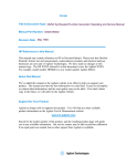

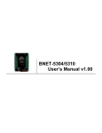
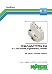


![User`s Manual MV2000[SU:M] Ventilator System 0470](http://vs1.manualzilla.com/store/data/005841388_1-c867b5a0773523e6306e353a41d4c56d-150x150.png)