1
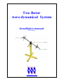
Two Rotor
Aero-dynamical System
Installation manual
PCI version
www.inteco.com.pl
TRAS system
INSTALLATION MANUAL
NOTES
2
TRAS system
INSTALLATION MANUAL
SAFETY OF THE EQUIPMENT
The equipment, when used in accordance with the supplied instructions, within the parameter set for its
mechanical and electrical performance, should not cause any danger to health or safety if normal engineering
applications are observed.
If, in specific cases, circumstances exist in which a potential hazard may be brought about by careless or
improper use, these will be pointed out and the necessary precautions emphasised.
Some National Directives require to indicate on our equipment certain warnings that require attention by the
user. These have been indicated in the specified way by labels. The meaning of any labels that may be fixed to
the equipment instrument are explained in this manual.
Risk of electric shock
PRODUCT IMPROVEMENTS
The Producer reserves a right to improve design and performance of the product without prior notice.
All major changes are incorporated into up-dated editions of manuals and this manual is believed to be correct at
the time of printing. However, some product changes which do not affect the capability of the equipment, may
not be included until it is necessary to incorporate other significant changes.
3
TRAS system
INSTALLATION MANUAL
ELECTROMAGNETIC COMPABILITY
This equipment, when operated in accordance with the supplied documentation, does not cause electromagnetic
disturbance outside its immediate electromagnetic environment.
COPYRIGHT NOTICE
© Inteco Limited
All rights reserved. No part of this manual may be reproduced, stored in a retrieval system, or transmitted, in any
form or by any means, electronic, mechanical, photocopying, recording or otherwise, without the prior permission
of Inteco Ltd.
ACKNOWLEDGEMENTS
Inteco Ltd acknowledges all trademarks.
IBM, IBM - PC are registered trademarks of International Business Machines.
MICROSOFT, WINDOWS are registered trademarks of Microsoft Corporation.
MATLAB and Simulink are registered trademarks of Mathworks Inc.
4
TRAS system
INSTALLATION MANUAL
CONTENTS
1. INTRODUCTION............................................................................................................................................. 6
2. COMPONENTS OF THE SYSTEM............................................................................................................... 7
3. UNPACKING AND CHECKING THE ITEMS ............................................................................................ 8
4. ASSEMBLY OF THE MECHANICAL CONSTRUCTION ..................................................................... 10
5. RT-DAC BOARD INSTALLATION ............................................................................................................ 11
5.1 RT-DAC/PCI BOARD CONNECTORS ............................................................................................................ 12
5.2 DRIVER INSTALLATION ................................................................................................................................ 13
6. CONNECTING THE POWER INTERFACE ............................................................................................. 14
7. SOFTWARE INSTALLATION .................................................................................................................... 16
8. STARTING AND TESTING ......................................................................................................................... 20
9. OPERATION AND SECURITY NOTES................................................................................................... 22
5
TRAS system
INSTALLATION MANUAL
1. INTRODUCTION
This manual contains a description of the components of the Two Rotor Aerodynamical
System, assembly instructions and test procedures. The procedures described in this manual
will ensure correct:
•
assembly of the system,
•
RT-DAC interface board installation,
•
cable connections between the mechanical part of the model, Power Interface and
PC.
6
TRAS system
INSTALLATION MANUAL
2. COMPONENTS OF THE SYSTEM
To use the system the following software and hardware components are required:
• Pentium or AMD based personal computer.
•
Microsoft Windows 2000/XP
•
MATLAB version 6.5 or 7 (R14 SP2/SP3) or R2006a/b, R2007a, R2008a/b or
R2009a with appropriate versions of Simulink RTW and RTWT toolboxes (not
included),
•
If MATLAB 6.5 is used the MS Visual C++ compiler is needed.
•
RT-DAC/PCI Programmable Input/Output board to install in the PC,
•
Inteco TRAS set-up consisting of the TRAS Mechanical Unit and TRAS Power
Interface Unit,
•
CD-ROM with TRAS software and e-manuals (in pdf format):
•
this manual,
7
TRAS system
INSTALLATION MANUAL
3. UNPACKING AND CHECKING THE
ITEMS
Carefully unpack the items, and remove all packaging and securing material. You should have
the following items (Fig.3.1):
•
TRAS beam and leg, with DC motors, rotors, counterbalance, sensors and attached
ribbon signal cables and power cables,
•
TRAS support,
•
couplings bolts (2) and special allen wrench,
•
fixing clamp (1) and fixing bar (1),
•
TRAS Power Interface,
•
Emergency switch,
•
Main power cable,
•
RT-DAC/PCI board with rear bracket connector and ribbon cables (3)
•
CD-ROM (Documentation: User’s Manual, this manual, software),
•
Packing List.
The exact specification you will find on the Item List. If any item is missing or damaged
please, contact Inteco.
Carefully follow the installation steps described below. Only correct
installation procedure ensures proper operation of the system
8
TRAS system
INSTALLATION MANUAL
Fig 3.1 The TRAS set-up, not assembled
9
TRAS system
INSTALLATION MANUAL
4. ASSEMBLY OF THE MECHANICAL
CONSTRUCTION
Components of the mechanical construction are given in Fig.4.1
security
covers
beam
leg
support
Fig.4.1 TRAS mechanical construction
Select the TRAS support and place it on the table. Join with the leg and TRAS beam. Insert
coupling bolts into mounting sockets and loosely screw them with the allen key provided
(Fig.4.2).
Fig 4.2 Coupling bolts
10
TRAS system
INSTALLATION MANUAL
5. RT-DAC BOARD INSTALLATION
The RT-DAC/PCI board contains sensitive electric components, which can be
easily damaged by static electricity, therefore the board should be kept in its
original packing until it is installed. During installation the board should be
handled carefully only by the edges to avoid static electricity discharge
To install the board:
•
Check, if CN3 connector of the board is connected to the rear bracket connector by
20-way short ribbon cable (included). If not, Connect 20-way ribbon cable to CN3
connector of the rear bracket connector.
•
Connect 20-way ribbon cable to CN1 connector of the board (see Fig.5.1),
•
Turn off the computer and remove the cover.
One empty PCI slot is required at the rear of your PC.
•
Find an empty expansion slot, remove the metal bracket,
•
Insert the RT-DAC/PCI board into the expansion slot, then secure the board with the
screws,
•
Secure rear bracket connector with the screw,
•
Replace the cover of the computer.
Next step is connecting the cables to the TRAS Power Interface (Fig.5.2).
Before removing the cover turn OFF the computer and disconnect the
mains cable
11
TRAS system
INSTALLATION MANUAL
5.1 RT-DAC/PCI BOARD CONNECTORS
CN3
RT-DAC4 / PCI-D
CN5
CN3
JP4
JP1
XILINX
CN2
SW2
CN7
PLX
CN1
SW1
CN4
CN6
Fig. 5.1. RT-DAC/PCI board and location of connectors
Fig. 5.2 shows connection the ribbon cables to the RT-DAC/PCI interface board.
Power interface
CN3
CN1
PC
CN1
RT-DAC card
CN3
CN3
2 x 20-way ribbon cable
Rear bracket
connector
Fig.5.2. RT-DAC/PCI cables connection
12
TRAS system
INSTALLATION MANUAL
5.2 DRIVER INSTALLATION
The driver for RTDAC/PCI board has to be installed because the board is of the PCI type.
Administrator privileges are required for driver installation.
Windows 2000/XP installation
•
Start Microsoft Windows 98/2000/XP
•
System detects new PCI device
•
Select Next, then Display a list....
•
Select Other Devices, then Next
•
Select Have a disk, then Browse
•
Select path CD:\driver\Win9x2K\RTDAC_PCI9030.inf, then Open
•
Select OK and Next, and Next
•
Select Finish
•
If Windows propose to restart the computer select Yes.
13
TRAS system
INSTALLATION MANUAL
6. CONNECTING THE POWER
INTERFACE
The general diagram of power interface connections is given in Fig. 6.1.
Before connecting the cables turn OFF the computer
There are two kinds of cables attached to the mechanical unit: 1 ribbon cables from the
encoders and 1 round cables controlling the motor and 1 round cable from the
tachogenerators. Notice, that the cables are terminated by different types of plugs.
In order to connect cables go through the following steps:
•
Check the position of the Power Switch located on the back side of the Power Interface
box – it must be in the „0” (OFF) position.
•
Connect the cables:
⇒ plug the 20-way ribbon cable from the RT-DAC/PCI board into the CN1 socket,
⇒ plug the 20-way ribbon cable from the rear bracket connector into the CN3
socket,
⇒ plug 10 - way ribbon cables from the encoders into the connectors marked as E
(Fig 6.1 ).
•
Connect two round cables: controlling DC motors, respectively: to the M socket and
cable from tachogenerators to the T socket,
•
Connect the emergency switch cable to the Em socket,
•
Plug the mains power cable to the socket located on the back side of the Power Interface
box.
Notice, that the connectors and the sockets are clearly marked using the
convention presented in Fig. 6.1
14
TRAS system
INSTALLATION MANUAL
STOP
Security switch
20-way ribbon cable
Fig. 6.1 Power Interface and connecting cables
15
TRAS system
INSTALLATION MANUAL
7. SOFTWARE INSTALLATION
The installation program has to be started by a system administrator
To start the installation program insert the CD-ROM into the drive, and run manager.exe
placed in the main directory. From the INTECO Software manager application window,
select TRAS Toolbox Installation. You will see the window (Fig. 7.1).
Fig. 7.1
Click the START button to start the installation program, or EXIT to quit.
If you select the START option you will see the license information. Read the license
agreement carefully. If you accept the license terms mark the checkbox and click the Next
button.
The window that follows asks you for your name and the name of your company (Fig.7.2).
16
TRAS system
INSTALLATION MANUAL
Fig.7.2
If you click the Next you will see an important dialogue window containing your current
MATLAB settings (Fig. 7.3). You will be informed about the version of your Windows
system.
You must select the appropriate version of the MATLAB software installed.
Fig. 7.3
Browse your system directories and select the appropriate directory. The program
automatically detects the presence of the matlab.exe file and closes the dialogue window. The
selected location will be displayed in the Matlab location window (Fig.7.4).
17
TRAS system
INSTALLATION MANUAL
Fig. 7.4
If you have completed installation settings click the Next button to start the installation
procedure. The end of installation process will be confirmed by the appropriate window
(Fig.7.5).
18
TRAS system
INSTALLATION MANUAL
.
Fig.7.5
The computer has to be restarted after the installation process.
To uninstall the software select the appropriate option from the Software Manager window.
Uninstalling process will be performed automatically.
19
TRAS system
INSTALLATION MANUAL
8. STARTING AND TESTING
For safety reasons it is not allowed to start the system if the plastic security
shield is removed.
In order to test the system perform the following steps:
•
Install the TRAS software. For this purpose refer to Section 7.
•
According to you selection (1-degree or 2-degrees of freedom experiment) fix one of
axis using the included clamp or fixing bar (Fig.8.1, Fig.8.2)
Fig. 8.1 Fixing one degree of freedom
20
TRAS system
INSTALLATION MANUAL
Fig.8.2 Fixing bar
•
If the RT-DAC/PCI board has been properly installed and ribbon cables connected
turn on your PC,
•
Start MATLAB and type TRAS command,
•
Switch on the mains (back side of the panel)
•
Blue LED on the front panel will alight,
•
Switch the power on (ON),
•
Red LED on the front panel will alight,
•
run Manual Setup application to perform the test, described in the section Starting,
testing and stopping procedures in TRAS User’s Manual, to check connections of the
sensors to the Power Interface.
•
In the case of any unexpected behaviour of the system use the EMERGENCY
SWITCH. After using the emergency switch, you have to turn and press switch and
next press the ON button in order to start the system again.
•
Now, you can perform your own experiments
•
If your experiments are finished, stop the MATLAB application. Switch off the mains.
21
TRAS system
INSTALLATION MANUAL
9. OPERATION AND SECURITY NOTES
•
It is not allowed to start the system if the plastic security shields are removed,
•
Allow good air circulation around the Power Interface box for correct cooling of
radiators, do not cover the fan.
22