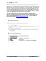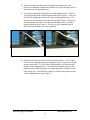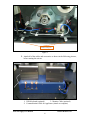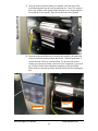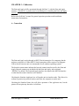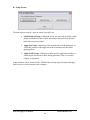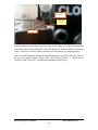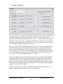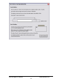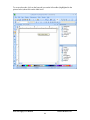
1
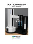
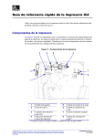
Hudson Print and Apply USER MANUAL Rev 1.1 10 Stern Avenue, Springfield, NJ 07081 Tel: 973-376-7400 Fax: 973-376-8265 Table of Contents CHAPTER 1 - Overview .................................................................................................... 2 A. System Requirements ............................................................................................. 2 B. Environmental Requirements ................................................................................ 2 CHAPTER 2 – Installation ................................................................................................ 3 A. Unpack the Print and Apply .................................................................................. 3 B. Installing Media ................................................................................................... 10 CHAPTER 3 - Calibration............................................................................................... 12 A. Connection ........................................................................................................... 12 B. Setup Screen ......................................................................................................... 13 C. Label Setup ........................................................................................................... 14 D. Apply Nest Setup .................................................................................................. 18 E. Hardware Setup.................................................................................................... 14 CHAPTER 4 – Operation ................................................................................................ 20 A. Creating Labels .................................................................................................... 20 B. Setup and Testing Apply Profiles ........................................................................ 24 C. SoftLinx Operation .............................................................................................. 26 CHAPTER 5 - Maintenance ............................................................................................ 28 A. Maintenance ......................................................................................................... 28 B. Cleaning the Print and Apply .............................................................................. 28 C. Cleaning the Printer............................................................................................. 28 CHAPTER 6 - Warranty & Service Agreement Terms and Conditions ........................ 29 A. Warranty ............................................................................................................... 29 B. Service Agreements .............................................................................................. 30 Print and Apply User Manual Hudson Robotics, Inc. i WARNING- - This product may be used only in the manner described in this manual. When used other than as specified, the safety protections provided by the equipment may be impaired. TABLE OF SYMBOLS: The following symbols are to alert your attention to important information or warnings that may present some hazards. These symbols may not appear in the manual or on the product. WARNING Possible hazardous situation could result in serious injury. NOTE A statement that is cautionary; operating tip; instrument damage may occur if not followed. HINT Helpful hints and additional information LIST ! List of instructions; parts Important information Specifications Electrical Hazard CAUTION Print and Apply User Manual Hudson Robotics, Inc. ii CHAPTER 1 - Overview The Print and Apply is an automated Barcode Labeling System. It creates and attaches printed labels to any SBS-standard microplate or microplate lid. The Print and Apply can apply labels any of the four sides of a microplate. The Print and Apply’s applicator head has 35mm of vertical travel which can hit anywhere on a standard microplate. The Print and Apply has an optional barcode scanner that can be mounted within range of the base, so you can print and confirm barcodes in one step. For a complete “walk away” system, the unit can be integrated with a Hudson Robotics PlateCrane EX. This manual will explain how to setup your Print and Apply to achieve optimal efficiency. If you have any questions or comments about the contents of this manual, please contact Hudson Robotics, Inc. at +1-(973) 376-7400. For more information, please visit our website at http://www.hudsonrobotics.com. A. System Requirements The Print and Apply needs the following to optimally run: 32” x 24” benchspace Clean, dry air with a 1/4” fitting and air line achieving a maintainable 80 psi, 3.0 cfm 120 VAC, 50-60 Hz, 4 amps PC with Windows XP or Windows 7, with CodeSoft 9.1 or later and SoftLinx V or later installed. B. Environmental Requirements Operating Temperature: Operating Humidity: Storage Temperature: Altitude: Ventilation 15 to 40C (59 to 104F) 0 to 85%, no condensation -20 to 65C (-4 to 149F) Up to 2000m Fans Require +2” of free space in front of them Print and Apply User Manual Hudson Robotics, Inc. 2 CHAPTER 2 – Installation A. Unpack the Print and Apply WARNING- - Power switch must be turned OFF during entire installation procedure. DO NOT loosen or tighten any screws or touch parts not specified in the instructions. Never force any component to fit. The Print and Apply system weighs 50 lbs. and should be handled with care to avoid mishaps. Overview: The Print and Apply will arrive in three separate boxes. The Zebra box contains the printer portion of the system. The Hudson box contains the applicator portion of the system. The third box contains the alignment base for the printer which connects the printer to the applicator. Any additional components will be packed in the Hudson box along with the applicator. Below are the following steps to unpack the system: 1. Open the third box and remove the alignment base from the box and place it on the table that will hold the Print and Apply system. Print and Apply User Manual Hudson Robotics, Inc. 3 2. Open the Hudson box and remove the applicator from the box, also remove any additional components from this box. Place the applicator on the table next to the alignment base. 3. You will now attach the applicator base to the alignment base. To do so, you will open the latches on the alignment base (See Figure 3). Then you will slide the alignment base into the cutout in the applicator base. You will now move the latches down until they meet the catches. Slowly turn the latch handles until they close and push the handle down to lock the latch into location (See Figure 4). Slowly move the alignment base to make sure that the bases are securely attached. Figure 3 Figure 4 4. Open the Zebra box and remove the Printer from the box. You will have to remove the shipping straps from around the printer, before removing the printer from the box. You will slowly lift the printer out of the box and install it on the alignment base. You will place the printer on top of the alignment base and match up the two countersunk holes with the two ball end leveling feet. The ball end leveling feet will keep the printer secured onto the alignment base (See Figure 5) Print and Apply User Manual Hudson Robotics, Inc. 4 Printer Leveling Feet Figure 5 5. Attach all of the cables and accessories as shown in the following pictures, before turning the unit on. 1 2 3 1- USB Keyboard (optional) 3- Monitor Cable (optional) 2- Communication Cable for Applicator (Attach to computer) Print and Apply User Manual Hudson Robotics, Inc. 5 1 2 3 1 4 1234- Communication Cable to Rear of Printer Optional Barcode Cable Power Cable for Applicator USB cable for Printer (goes to computer) Print and Apply User Manual Hudson Robotics, Inc. 6 2 1 1- Air Pressure Regulator set to 60 PSI w/ ¼” Quick disconnect fitting. User supplies air input of 80 PSI (5.5 bar) or greater to this unit. 2- Vacuum Lines Print and Apply User Manual Hudson Robotics, Inc. 7 1 1. 1/8” Air Blast Tubing. (Color may vary.) Print and Apply User Manual Hudson Robotics, Inc. 8 NOTE: DO NOT DISCARD the Hudson or Zebra Printer box. These cartons have been specially created for these products and must be used for any additional shipping of the instruments to prevent damage. The Print and Apply boxes should include the following: Print and Apply Applicator Print and Apply Alignment Base Zebra Printer Power cord (s) Communication cable(s) Monitor USB Cable Keyboard Mouse Barcode Scanner (optional) 6ft of 1/4” air tubing User Manual (This document) Print and Apply User Manual Hudson Robotics, Inc. 9 B. Installing Media (Labels) After the PA1000 is setup correctly the media for the printer must be installed. 1. Open the front cover of the printer. Inside the printer wall is a schematic of how the media should run through the printer. Use this as a guide to position the media and print ribbon. 2. The print head must be lifted up so the print ribbon and media can go through the print head area. To lift up the print head slide the head bar labeled below counterclockwise until the head pops up. Print head arm Print and Apply User Manual Hudson Robotics, Inc. 10 3. Once the media and print ribbon are installed, slide the edge of the media backing between the air blast and strip bar. Once it is exposed below the air blast, pull enough media through so it is long enough to fit around the lower spindle. Tape the media to the lower spindle. 4. Once the media and ribbon are secured to the spindles, the print head can be lowered back into position and closed. After the print head is closed, the unit will be in a paused mode. To un-pause the printer, simply press the pause button. Once the unit is un-paused, or powered up, it will perform a short calibration requiring a feed of multiple labels. Remove the built up labels from the air blast before running the unit. Build up after calibration Pause Button Print and Apply User Manual Hudson Robotics, Inc. 11 CHAPTER 3 - Calibration The Print and Apply is fully operational through SoftLinx V, with the Print and Apply interface. Codesoft 9.1 or greater must be installed prior to installing the Print and Apply interface. Refer to the SoftLinx V manual for general operation procedures and installation instructions for interfaces. A. Connection The Print and Apply works through an RS232 Serial connection. For computers that do not have serial ports, a USB to RS232 Serial connection will be required. An Edgeport USB to Serial converter unit is recommended for all windows operating systems. The barcode scanner name indicates the barcode scanner interface used by the Print and Apply. Barcode scanners are included with the Print and Apply, and are named “MS3204” by default. The Print and Apply interface also requires the MS3204 interface or other barcode scanner interface to be installed. Checking the Simulate Applicator box will put the unit in simulate mode. This allows for software operation of protocols but does not allow the computer to run the unit. Checking the Simulate Printer box will allow operation of the applicator unit, but the printer will not print any barcodes via SoftLinx. Print and Apply User Manual Hudson Robotics, Inc. 12 B. Setup Screen The unit requires setup in 3 steps to ensure successful use: Label Retrieval Setup: Calibration of how the unit picks up labels, which includes calibration of the vacuum and airblast, and position of the label head when retrieving a label. Apply Nest Setup: Calibration of the rotational nest on the applicator, as well as the position of the applicator head in relation to the nest when applying labels. Apply Profile Setup: Calibration of plate-specific application profiles, to ensure proper placement of labels during operation. (This is covered in Chapter 4: Operation) Setup cannot be run in simulate mode. All functions in setup require the print and apply unit to be active and connected to the computer. Print and Apply User Manual Hudson Robotics, Inc. 13 C. Hardware Setup Prior to Label Setup, the hardware must be configured to pick up labels properly. The apply head can be controlled from the label retrieval or apply head setup screens. 1. Move the apply head out of the way of the air blast. 2. Press the Feed button on the front of the printer to advance one label to the tear off position. Feed Button 3. The label should stop right at the edge of the strip bar as seen below. Strip Bar Air Blast 4. If the label is not in the correct location, it will have to be adjusted through the printer’s front panel. 5. To get into the submenus, press the (Setup-Exit) button on the front panel of the printer. Print and Apply User Manual Hudson Robotics, Inc. 14 6. Press the (Next-Save) button until the tear off setting is displayed, using the (+) and (–) buttons move the label until it is in the correct location. 7. Remove that label and press the feed button again 2-3 times to confirm the proper tear off location. 8. To save the tear off position press the (Setup-Exit) button, this will send it to the save options, the first option will be Save Permanently, press the (Next-Save) to accept the save command. 9. After the settings have been saved correctly the printer will automatically go back to Main screen, where it shows Printer Ready. *The tear off position may need to be adjusted if the media is removed to clean the printer or when a new media/ribbon roll is installed. ** Must allow 25 labels to be printed trough the printer when a new roll is installed, since it needs time to find its natural resting location. Print and Apply User Manual Hudson Robotics, Inc. 15 D. Label Setup To calibrate the unit for label retrieval, the user must obtain vacuum cutoff values and teach the unit the location of the label retrieval point. The vacuum cutoff values are used for label detection during operation, and should be taught before teaching the label retrieval point. To obtain the correct vacuum cutoff values, the user must obtain a single label from the printer. Ensure that the air sources are properly attached to the unit at 60 psi. Press the “Teach” button, and ensure the head is clear of all debris. The unit will turn the vacuum on, then the airblast on. The unit will then prompt the user to place a label on the head. Place a label on the head (non-adhesive side), ensuring all holes of the head are covered, and then press OK. The unit will once again turn the airblast on and off. It will calculate cutoff values for the unit. Press the “Save” button to retain those values. The correct location for the label retrieval point is about 0.030” (width of a business card folded) directly above where the label from the printer is placed after a barcode is printed, as seen below. The front edge of the tamp head should be aligned with the front edge of the strip bar, as seen below. It is highly recommended that the applicator head is completely centered over and parallel to the label that it is picking up. Failing to position the head parallel to the label at pick up will result in crooked label application. Print and Apply User Manual Hudson Robotics, Inc. 16 Front Edge of tamp head Front edge or strip bar 0.030” Gap Once the head is over the label, press the “Save Point” button. It is highly recommended to test label retrieval now. Press the “Test Label Retrieval” button to test how it picks up a label. If it picks up a label within 2 seconds of its first attempt, it is taught properly. If the user needs additional assistance in understanding this screen, the user may click on the two help buttons labeled “What is the Label Retrieval Point?” or “What are the Vacuum Cutoff Values for?” for additional information during setup. Print and Apply User Manual Hudson Robotics, Inc. 17 E. Apply Nest Setup To teach the unit how to apply a label to the selected nest, the user must teach the unit the orientation of the nest by facing the side labeled “side 1” towards the body of the applicator. With standard Print and Apply Units, side 1 is the longest side of the nest that the colored corner, noted as A1, is touching. Other nest types that may be used will have additional documentation to note which side is A1. The user must also teach the unit how to face the applicator head towards the selected nest. The selected nest’s Side 1 should be taught first. Face Side 1 towards the applicator arm. Place the teach plate into the rotational nest. Retract the arm, put the head up, face the arm such that it is facing side 1 of the teach plate in the nest. Extend the arm closely to the teach plate, then in 5mm increments, extend the arm so that it slightly pushes against the nest and rotates it in the proper position. Retract the arm, and save this position as Side 1. Press “Save Nest Orientation as Side 1” to do this. While in this position, remove the teach plate. Move the arm in a position such that the bottom edge of the head is parallel to and touching the top edge of the rotational nest’s surface that the plate sits on. Teach this point as the Apply position. Press “Save Arm Position as Apply” to do this. After pressing this button, return the teach plate to the nest. The unit will do a calibration procedure to save the point as the apply position, pushing against all 4 sides of the teach plate. The user may also click the “How do I save the arm and nest positions?” button for a graphical explanation of teaching, as shown on the next page. Print and Apply User Manual Hudson Robotics, Inc. 18 Print and Apply User Manual Hudson Robotics, Inc. 19 CHAPTER 4 – Operation A. Creating Labels Codesoft v.9 is required to create labels. This section also assumes that the Zebra 110Xi4 printer is attached to the computer. Basic labels used with the Print and Apply are 2.5 inches wide by 0.25 inches tall. (63.5mm x 6.35mm) To create the label template, open Codesoft. Select New Label Document and ensure the label size has a 2.500 in. width and a 0.2500 in. height. Print and Apply User Manual Hudson Robotics, Inc. 20 To create a barcode, click on the barcode icon on the left toolbar (highlighted in the picture below) then click on the label itself. Print and Apply User Manual Hudson Robotics, Inc. 21 The barcode type, as well as attached counters can be modified on the screen below. Select a symbology that is compatible with the barcode scanner. Generally, the Code 39 and Code 128 barcodes are compatible. Print and Apply User Manual Hudson Robotics, Inc. 22 In addition, counter variables are used to automatically increment the barcode during operation. Please note – both the Shared box and ISO counter box MUST be checked to allow incrementing barcodes in SoftLinx. Once the label is set up, the user may print the barcode from Codesoft to ensure proper printing of the label. See Codesoft documentation or help files for more information. Print and Apply User Manual Hudson Robotics, Inc. 23 B. Setup and Testing Apply Profiles Apply profiles tell the unit how to apply a label to a specific plate type. The Apply Profile setup screen is available through the main Setup screen of the Print and Apply interface. To define an apply profile, the user must specify where to apply a label on each side of a specific plate, by specifying the apply height on each side. The Apply Height is the distance between the bottom of the plate and the bottom of the desired location of the label, in millimeters. To save the apply profile, enter 4 apply heights for the plate – even if a side would not be used. Press the “Save Profile” button. The user will be prompted to place the plate into the nest to allow the unit to calibrate the profile. Additional graphical help is available by clicking the “How do I do this?” button. Note: If the user wishes to label a plate when lidded, and a plate without, the user will have to create two separate apply profiles for that plate – one for plates with lids, one without. Multiple apply profiles can be made for a single plate type. Users may also test the profile with labels created from Codesoft. Print and Apply User Manual Hudson Robotics, Inc. 24 Print and Apply User Manual Hudson Robotics, Inc. 25 C. SoftLinx Operation The print and apply interface has two steps available in SoftLinx. The user may re-orient the rotational nest by selecting the “Move Applicator Nest” step. The main function of the Print and Apply is accessed by the “Print and Apply Label” step. This requires a Codesoft Label file and an Apply profile to be available. Previous sections of the manual note how to create both items required for functioning. Enter the location of the file, the apply profile for the plate to be used, the rotational nest, the sides in which the label will be applied, and whether or not a scanner validation is required. During the execution of a SoftLinx protocol, the Print and Apply’s nest will be moved to a “Side 2” orientation. It is imperative that the user teaches the plate crane point or other plate mover positions related to the print and apply in a “Side 2” orientation. A basic Print and Apply protocol is shown on the next page. This protocol is used to label multiple plates located in a set of stacks moved by a Hudson PlateCrane. Print and Apply User Manual Hudson Robotics, Inc. 26 Print and Apply User Manual Hudson Robotics, Inc. 27 CHAPTER 5 - Maintenance A. Maintenance WARNING- - Qualified personnel can perform all maintenance procedures in this manual. Only Hudson representatives should perform any maintenance not discussed in this manual. Gloves should be worn during any cleaning procedure. B. Cleaning the Print and Apply Note: DO NOT use/spray abrasive cleaners onto Print and Apply applicator. Clean the outside surfaces of applicator using cloth or sponge dampened with alcohol or mild glass cleaner. Clean Applicator head with alcohol or other residue-free solvent. Clean any spills on Print and Apply immediately. Only clean the exterior of the unit. DO NOT remove instrument covers to clean inside. Never allow water or fluid to leak inside the Print and Apply. C. Cleaning the Printer Note: DO NOT use/spray abrasive cleaners onto the Printer. The printer must be cleaned every time the media is replaced or when you are having issues printing correctly. You will need to clean the two white rubber rollers and the print head that are inside the printer. After cleaning the printer, allow the system to Print and Apply 25 labels to allow the printer to self-align the new media. Print and Apply User Manual Hudson Robotics, Inc. 28 CHAPTER 6 - Warranty & Service Agreement Terms and Conditions A. Warranty a. One-year coverage beginning on the factory ship date on all parts and labor including return shipping (to the customer) via UPS ground or equivalent. Warranty is limited to components and software purchased from or provided by Hudson Robotics, Inc. b. Technical support by trained personnel via telephone or email during normal business hours will be provided at no cost (exclusive of telephone toll charges incurred by the customer) during the warranty period. c. On-site service will be provided by Hudson Robotics, Inc. during the warranty period, if provided for in the customer quote for that purchased product. d. Factory return service is available for all products, under the following conditions. 1. The customer is responsible for packing of instrument and shipping to Hudson. The customer will be notified of nonwarranty repair costs, if any, prior to repair being started. 2. Damage incurred in transit to Hudson including, but not limited to, damage due to improper packing will be the responsibility of the customer and / or shipper. The customer is advised to retain the original packing material, including the cast foam padding, in the event service is required. Replacement packing materials are available from Hudson at cost-plus shipping (currently ~$175.00). 3. Hudson will pay return shipping to customer, via UPS ground or equivalent. Expedited shipping is available at additional cost. e. Updates to correct performance anomalies shall be provided at no cost during the warranty period subject to the warranty terms and conditions. f. Upgrades, which provide additional functionality, may be offered at reduced costs during the warranty period. g. Factory repairs must be pre-authorized by Hudson Robotics, Inc. and will include issuance of a Returned Materials Authorization (RMA) number. Customer certification of decontamination is required prior to return of any instrument(s) for factory service (instruments not certified decontaminated may be refused service and returned at customer’s expense). h. While Hudson Robotics, Inc. makes every effort to provide software and instruments suitable to a wide range of automation tasks, no guarantee is made as to the suitability of the hardware and/or software provided for a given application unless so stated in the written purchase agreement. i. Repair of failures, caused by but not limited, to misuse, fire, flood or other act of God, chemical or environmental exposure, or repair by persons not authorized by Hudson Robotics, Inc. may, at the sole discretion of Hudson Robotics, Inc., be charged at the prevailing hourly service rate (currently $162.50/hr for Factory Service, $162.50/hr for travel time and $325/hr for Field Service). Print and Apply User Manual Hudson Robotics, Inc. 29 B. Service Agreements I. Service Agreements, in one year periods, are available at prevailing rates and provide the following coverage in addition to the original warranty: a. One scheduled onsite maintenance service call per year of coverage to include evaluation and adjustment/repair to meet instrument performance specifications. b. Inspection and replacement of marginal components. c. If previous warranty or service agreement coverage has expired for more than 30 days pre-inspection and repair of instrument at customers expense prior to start of service coverage may be required. d. Pre-inspection may, at the service director’s discretion, be provided in place of the one scheduled on-site maintenance at no charge beyond that of the service agreement. e. Onsite service is priced by travel time to customer from an established Hudson site. 1. Zone I: Massachusetts, Connecticut, Rhode Island, New Jersey, New York, Pennsylvania, Delaware, and Maryland. 2. Zone II: All other locations. f. Payment terms are net thirty (30) days after the date of invoice. Customer will be invoiced. In case of delayed payment, Hudson Control reserves the right to decline service. g. This agreement may be terminated by either party upon default by the other party of any material obligation under this Agreement which default continues for thirty (30) days after written notice has been provided by the non-defaulting party. II. General Conditions. These apply to all products under warranty or service agreement. a. Excluded parts. Covered parts do not include chemicals, reagents, customer replaceable items, consumables, or other parts listed in the operator's or instruction manual as customer replaceable parts, sub-assemblies or accessories. Replacement of these items will be billed at prevailing rates. b. Hudson Control reserves the right to use repaired parts during the Coverage Period. For parts that have been replaced, Hudson Control is the sole owner of these parts and they cannot be sold or repaired by the customer or any third party. c. Key operator. Customer shall designate a key operator to a Hudson Control representative by telephone or email. Such operator shall be qualified to perform simple adjustments or corrections as requested by a Hudson Control representative. Failure to perform customer maintenance as specified in the Instrument Instruction Manual may result at Hudson Control’s option in 1) cancellation of this Agreement or 2) a service call invoiced by Hudson Control at its standard rates for service including travel. Print and Apply User Manual Hudson Robotics, Inc. 30 d. Warranty and service coverage does not include the following. Any service calls made as the result of the below shall be invoiced by Hudson Control at their standard rates including travel and labor expenses: 1. Damage caused by Customer misuse or operation outside of conditions prescribed in the Instruction Manual. 2. Damage caused by electrical surges or the use of improper sources, intervention of a third party, external influences such as fire, water damage, natural disaster, etc. 3. Relocation of the instrument. 4. Use of chemicals and accessories outside the specifications contained in the Instruction Manual. 5. Applications related issues. 6. Computer/ Hard drive crashes and failures e. Safe Working Environment. Customer shall provide the Hudson Control representative with facilities at Customer's location that comply with the applicable regulations of the Secretary of Labor promulgated under the Occupational, Safety and Health Act of 1970. f. This agreement sets forth the entire agreement and understanding between Hudson Control and Customer regarding service of the Instruments covered hereunder. This agreement may be modified only by writing and by authorized representatives of the parties. III. Custom Service Packages providing features to meet individual customer requirements may be arranged. Contact your sales representative or Hudson’s service director for availability and pricing. Print and Apply User Manual Hudson Robotics, Inc. 31