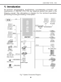
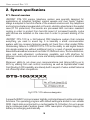
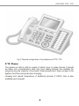
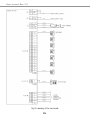
1
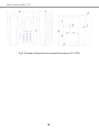
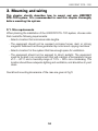
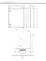
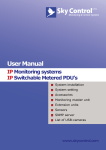
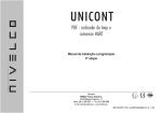
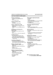
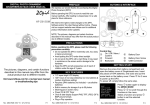
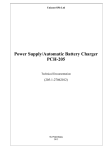
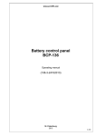
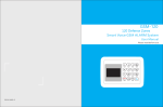
User manual Rev 1.3
Contents
1. Introduction.......................................................................................................................4
2. System specifications...................................................................................................5
2.1.. General overview...........................................................................................5
2.2. Maximum capacity.........................................................................................6
2.3. Electrical specifications...............................................................................6
2.4. Mechanical specifications...........................................................................6
2.5. Dimensions.......................................................................................................6
2.6. Environment limitations...............................................................................6
2.7. Cable requirements.......................................................................................7
2.8. Power supply requirements.......................................................................7
2.9. Key telephone parameters.........................................................................7
2.10. Phones.............................................................................................................8
3. Mounting and wiring......................................................................................................10
3.1. Site requirements..........................................................................................10
3.2. System unpacking..........................................................................................12
3.3. Examination before mounting...................................................................12
3.4. Stations and trunk lines wiring.................................................................12
3.5. External Public Address System
and external music source wiring.....................................................................14
3.6. Power supply wiring......................................................................................14
3.7. Turning ON the system................................................................................14
3.8. System programming..................................................................................14
4. Equipment supplied........................................................................................................17
5. Transportation and storage.......................................................................................18
6. Warranty............................................................................................................................19
7. Purchase information....................................................................................................20
8. Acceptance report.........................................................................................................21
9. Installation report............................................................................................................22
3
UNICONT DTS-100
1. Introduction
All technical characteristics, specifications, commissioning procedure and
maintenance of UNICONT DTS-100 key telephone system are given in the
following manual. This information is intended for the technical specialists,
performing mounting and testing of the system.
Fig 1. System Connection Diagram
4
User manual Rev 1.3
2. System specifications
2.1. General overview
UNICONT DTS-100 marine telephone system was specially designed for
applications at industrial facilities, marine vessels and river boats. System
design is adapted to harmful effects of the ambient environment. Key telephone
and carrier sockets are suspended on the anti-vibrating absorbers in the sealed
case (IP 53 protection). The boards are processed with corrosion-resistant
coating in order to protect from harmful impact of increased humidity. Locks
with latches are installed on the case door in order to prevent sticking of the
door.
UNICONT DTS-100 is a full-featured PBX telephone system that includes
everything you need to sound big. It is basically a small communication
system with big-company features usually not found from other similar PBXs.
Outstanding feature in UNICONT DTS-100 is the ability to add digital feature
into simple analog line without additional cost or a need of special equipment.
Essential business services such as Caller ID, SMS and voice/fax tone detection,
voice mail, auto attendant, conferencing capability, and LAN interface for
Ethernet connectivity and much more are already available as part of standard
features.
Moreover, ability to cut-down your communications cost (phone bill) by up to
60% by utilizing Call cost control/monitoring as well as sophisticated Least
Cost Routing (LCR) capability are already built in as part of value-added features
not offered by other competitors.
Fig 2. DTS-100 reference designator
A powerful ARM7 microprocessor digitally controls all speech paths and system
functions. The operating program with default settings is stored in non-volatile
ROM. User’s data is protected by a rechargeable Ni-Cd battery for up to seven
day’s continuous loss of system power. After resumption of system supply, the
battery is recharging automatically.
5
UNICONT DTS-100
On the whole, the system which consists of key telephone, extension boards and
regular phones, represents a contemporary, flexible and convenient telephone
system.
2.2. Maximum capacity
Maximum number stations
Maximum number of trunk lines
Public address system ports
External music source port
47+2*
12
1
1
* - 48 of internal stations is present, only in case of 1 digital and 47 analog or
digital phones are connected to DTS-100.
2.3. Electrical specifications
Input voltage
Power consumption
Ring generator
Battery backup supply
220-240 VAC , 50Hz
91W (max)
80 VRMS, 25Hz
24 VDC
2.4. Mechanical specifications
Case color
Protection
Door locking
Marine vibration absorber
Gray
IP 53
Latch locks 2 pcs.
4 pcs. (АКСС-25М type)
2.5. Dimensions
Case dimensions
Weight
760х600х210 mm
43 kg
2.6. Environment limitations
Operating temperatures
Operating humidity
0 ~ 40 °С
10 ~ 90%
6
User manual Rev 1.3
2.7. Cable requirements
Equipment
Digital keysets
Single line station
Add-on modules
Door phone
Cable
2 twisted pairs
1 twisted pair
1 twisted pair
2 twisted pairs
AWG
24 (0,22 mm2)
24 (0,22 mm2)
24 (0,22 mm2)
24 (0,22 mm2)
Max distance
400 m
1 km
400 m
100 m
2.8. Power supply requirements
220-240VAC, 50Hz input voltage is
telephone system. In case of input
immediately switches to backup power
four 6V or 12V batteries connected in
ampere-hours.
required for power supply of the key
voltage significant drop, the system
supply, 24VDC. To supply 24 VDC, use
series, with battery capacity of 6 ~ 40
2.9. Key telephone parameters
Key telephone system are advanced, user-friendly digital keysets, offering the
convenience of 3 soft buttons and a navigation key.
Features:
-.Trendy and Stylish LDP Family design
-.Multi Level 3 Line LCD (3 x 24)
-.24 Flexible buttons with dual-color LED’s
-.Call Log Feature
-.Wall Mountable (Bracket Optional)
7
UNICONT DTS-100
Fig 3. Physical configuration of key telephone of DTS-100
2.10. Phones
The system is able to dial by means of either tone or pulse phones. It should
be taken into consideration, that only tone dialing phones are suitable for
programming the majority of functions. Pulse phones don’t have access to the
system functions and parameter changing.
Housing and overall dimensions of additional phones P-2350, that is also
available upon request.
8
User manual Rev 1.3
Fig 4. Physical configuration and overall dimensions of Р-2350
9
UNICONT DTS-100
3. Mounting and wiring
This chapter shortly describes how to mount and wire UNICONT
DTS-100 system. It is recommended to read this chapter thoroughly
before mounting the system.
3.1. Site requirements
When planning the installation of the UNICONT DTS-100 system, choose a site
that meets the following requirements:
-Select a location that minimizes cable lengths.
-The equipment should not be exposed corrosive fumes, dust, or strong
magnetic fields such as those generated by motors and copying machines.
-Select a location for the system that has enough space for ventilation.
-The equipment should not be exposed to direct sunlight. The equipment
must be located in an environment that will maintain a temperature range
of 0 ~ 40°С and a humidity range of 10% ~ 90% non-condensing. The
location should have adequate lighting and ventilation, and should be dry and
clean.
Overall and mounting dimensions of the case are given at Fig 5
10
User manual Rev 1.3
Fig 5. System overall and mounting dimensions
11
UNICONT DTS-100
3.2. System unpacking
Check to see that the system package includes the following items (see also sec. 4):
- system distribution cabinet;
- mounting screws set;
- digital keyset;
- operating instructions;
- technical manual.
3.3. Examination before mounting
After unpacking the key telephone system, inspect for signs of physical damage
inflicted during transit.
-Check the insulation integrality of the cables at the contacts, as well as the
contacts in the terminal block, completeness of all the screws.
-Check the presence of fuses.
3.4. Stations and trunk lines wiring
According to the labeling of the terminal blocks, given at Fig 6:
-XS1 Group: IN LINE (С.О. №1~6) is designed for input trunk lines wiring;
-XS2 Group: Sys.tel.(STN №1) is designed for digital keyset wiring;
-XS3 Group: OUT LINE is designed for standard pulse and tone phones
wiring.
NOTE:
It should be pointed, that XS2:Sys.tel terminal group is assigned for
digital (not analog) telephone only.
12
User manual Rev 1.3
Fig 6. Labeling of the terminals
13
UNICONT DTS-100
3.5. External Public Address System and external music source wiring
UNICONT DTS-100 System provides the possibility of connecting of external
Public Address system. XS5 (P.A.) terminal group is assigned to wire the key
telephone system to the corresponding sockets of Public Address.
In addition to the standard background music, at the Music On Hold (MOH)
mode, UNICONT DTS-100 system allows to use other external music sources,
such as tape recorder or CD-player. XS5 (MUSIC) terminal block is used for
wiring of the external music source.
3.6. Power supply wiring
Main power supply is realized through XS6 terminal block. Backup power supply
(24V) is connected to the XS5 terminal block.
Please, check the polarity of power source cable.
3.7. Turning on the system
After system wall mounting, trunk and stations wiring and connecting, UNICONT
DTS-100 system is ready to be activated and programmed.
-Check the presence of the fuses.
-After supply mains connected, turn the power switch on, then the power
LED at the face panel inside will be lights on.
3.8. System programming
UNICONT DTS-100 System is shipped with presetting by default. The system
comes ready to use after the power is ON. Then you should program your
individual settings for system functioning in accordance to your requirements or
application. Use Digital Keyset supplied or PC to program the UNICONT DTS100 system.
The following sections are most commonly used basic settings with marine
adaptation. For more detailed information on system programming, please refer
to the manual “Programming Guide” given on CD supplied with the system.
14
User manual Rev 1.3
3.8.1. First time starting up
Default settings (On the mainboard of system):
- SW2 jumper – ON
- Jumpers group SW1 – all in ON position, except 4.
That configuration allows you to store all new settings.
After switching on the power please wait until the system boots up. All following
manipulations are described for system phone keyset.
3.8.2. Entering the programming mode
To get into the programming mode please press on buttons
in following sequence: Speaker, TRANS/PGM, *, #, TRANS/
PGM
3.8.3. PAGE settings (Public Address output)
-Enter the programming mode sec 3.8.2
-Press 181, CO10 (on the right keyboard - LOOP BUTONS)
-Set the working timeout (0 – 255 sec.)
-Press HOLD/SAVE
-Press TRANS/PGM (allowing of Public Address transmission)
-Enter 111, then “enter STA ranger” appears.
-Enter 100, 100 for instance. That means that only station no. 100 is able
to get on for P.A. contact
-Press CO8 loop button
-Push on 1 (“OFF” is changing to “ON” on the screen).
-Press on HOLD/SAVE
15
UNICONT DTS-100
3.8.4. P.A. relay contacts control
-Enter the programming mode sec 3.8.2
-Enter 168, CO1 loop button
-Press on 3 (choosing relay no. 1)
-Press on HOLD/SAVE
Verification: Pick up the phone, ring 545 and speak. At this moment,
the system transmits the signal to P.A. output and makes the contact
of relay on.
3.8.5. Reset all settings
On the mainboard of system:
- SW2 jumper – OF (battery off)
- Jumpers group SW1 – all in ON position, including 4.
16
User manual Rev 1.3
4. Equipment supplied
-Marine telephone station UNICONT DTS-100
-System telephone
-User manual
- Original technical documentation and CD with all supported software and
information.
17
UNICONT DTS-100
5. Transportation and storage
Transportation is performed using the cardboard wrapper at any enclosed
transport facility.
Marine telephone system UNICONT DTS-100 must be stored in enclosed
space at –20…+45°C.
18
User manual Rev 1.3
6. Warranty
This product is warranted to be free of defects in materials and construction.
Warranty period of storage life is within the 18 months from the date
of initial purchase.
Warranty period of service life is within the 12 months from the date
of installation, but no longer than 18 months from the date of initial
purchase.
During these warranty periods the Owner obtains free of charge repairing and
part replacement, if only defect caused by Manufacturer’s fault.
Warranty repairs available if following documents are present:
- actual User Manual;
- marked Purchase information, Acceptance and Installation reports.
If there is no Acceptance or Installation marks, then the period of warranty is
dated by day of System purchasing.
Warranty is void in following cases:
-when the warranty period expired;
-if the rules of mounting, operation and transportation are infracted;
-if device have been interacted with not appropriate electronic equipment;
-if vendibility or case integrity is lost for some reasons, beyond the control of
the Manufacturer;
-if device have been repaired by any person who is not an authorized by
Manufacturer.
Duplication of actual User Manual is not allowed. If this User manual is lost, the
Owner forfeits his right for free repairing and fixing during the warranty period.
19
UNICONT DTS-100
7. Purchase information
Marine telephone system UNICONT DTS-100
Serial number __________________
Firmware version _____________
Package date _____________
Manufacturer
UNICONT Co. LTD
Stamp here
20
User manual Rev 1.3
8. Acceptance report
Marine telephone system UNICONT DTS-100 is in accordance with
documentation and is considered in working order.
Serial number __________________
Delivered by:
Company name _______________________________________________
Full name _________________________
signature _____________
Accepted by:
Company name _______________________________________________
Full name _________________________
Acceptance date _________________
21
signature _____________
UNICONT DTS-100
9. Installation report
Marine telephone system UNICONT DTS-100
Serial number ___________________
The Unit has been commissioned.
Date ___________________________
Place of installation:
___________________________________________________
___________________________________________________
Installed by___________________________________________
(full name, signature)
Serial number __________________
Delivered by:
Company name _________________________________________________
Full name ______________________________
signature ____________
Accepted by:
Company name _________________________________________________
Full name ______________________________
Acceptance date __________________
22
signature ____________