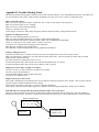
1
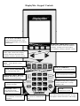
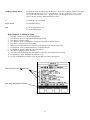
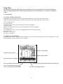
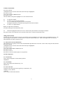
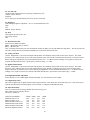
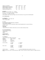
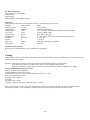
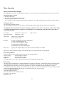
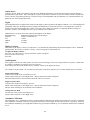
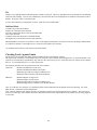
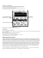
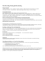
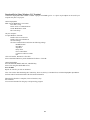
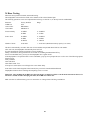
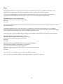
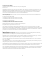
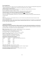
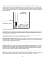
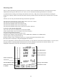
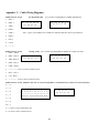
Sadelco DisplayMax Operator’s Manual
This document contains information proprietary to Sadelco, Inc. The information in this document is not to be used or duplicated in
any manner without prior written consent from Sadelco.
DisplayMax Manual Part No. ST1008
Rev. 08-31-2001
Copyright 1999, 2000, 2001 Sadelco, Inc. Patent Pending
DisplayMax 600
47 – 600 MHz
Scanning Signal Level Meter
DisplayMax 600 CLI
47 – 600 MHz
Scanning Signal Level Meter and Calibrated Leakage Detector
DisplayMax 800
5 – 872 MHz
Scanning Signal Level Meter
With Sub Band and Ingress Sweep
DisplayMax 800CLI
5 – 872 MHz
Scanning Signal Level Meter and Calibrated Leakage Detector
With Sub Band and Ingress Sweep
Warranty
Sadelco warrants all instruments against defects in material and workmanship for a period of twelve months after shipment. Sadelco
will repair or replace any assembly or component (except batteries) found to be defective under normal use during this period.
Sadelco’s obligation under this warranty is limited solely to repairing any instrument which, in Sadelco’s opinion, proves to be
defective within the scope of the warranty when returned to the factory. Transportation to the factory is to be prepaid by the
purchaser. Return transportation via UPS surface will be provided by Sadelco. Should the customer request an alternate shipping
method, the customer will be solely responsible for any charges in excess of UPS surface rates.
This warranty does not apply to any products repaired or altered by any persons not authorized by Sadelco, or not in accordance with
instructions furnished by Sadelco. If the instrument is defective as a result of misuse, improper repair, or abnormal conditions of
operation, the warranty will become void. In doubtful cases, we will contact the purchaser for non-warranty repair authorization.
Please notify us if an estimate is required.
Sadelco assumes no responsibility for its products being used in a hazardous manner either alone or in conjunction with other
equipment. Sadelco assumes no liability for secondary damages and, in any event, Sadelco’s liability for breach of warranty under
any contract or otherwise shall not exceed the purchase price of the specific product shipped and against which a claim is made.
An RMA number is not required to return either warranty or repair units to Sadelco. However, Sadelco assumes no liability for any
product in transit to Sadelco. Please make sure to include a description of the problem or symptom along with your complete
company name, address, telephone, fax, and contact person.
For Warranty or Repair Service return to:
Sadelco, Inc., 75 West Forest Ave. Englewood, NJ 07631 USA
Tel: 800-569-6299 (USA Only) Tel: 201-569-3323 Fax: 201-569-6285
e-mail: [email protected] Website: www.sadelco.com
1
Table of Contents
Keypad Control Diagram …………………………………………….. 3
Initial Startup …………………………………………………………. 4
Customizing Your Meter …………………………………………….. 4
Setup Menu ……………………………………………………………. 6
Cloning ………………………………………………………………... 10
Meter Operation………………………………………………………. 11
Battery ………………………………………………………. 11
Lights ………………………………………………………… 12
Display Contrast ……………………………………………. 12
Speaker ……………………………………………………… 12
Automatic Calibration ……………………………………… 12
Signal Level Measurement ………………………………………….. 13
General ………………………………………………………. 13
Single Channel Tuning ……………………………………… 14
Tuning by Frequency ……………………………………….. 14
Full Scan Tuning ……………………………………………. 14
Zoom …………………………………………………………. 14
Favorite Channel Tuning …………………………………... 14
Tilt ……………………………………………………………. 15
Sub Band (800 versions only) ………………………………. 15
Checking Levels Against Limits …………………………………….. 15
Digital Channel Measurement ………………………………………. 16
Data Recording, Printing and Downloading..……………………….. 17
Storage Capacity…………………………………………….. 17
Saving Measurements ………………………………………. 17
Recalling and Deleting Files …………………………………
Creating Excel Spreadsheets…………………………………
Download to Windows 3.11 Terminal……………………… 18
Download to Windows 95/98 HyperTerminal …………….. 19
Print Direct to Serial Printer ………………………………. 19
24 Hour Testing ………………………………………………………. 20
Hum ……………………………………………………………………. 21
Carrier to Noise ………………………………………………………. 22
Ingress Sweep (800 versions only) …………………………………... 22
Leakage Detector (CLI versions only) ………………………………. 23
Appendix A: Specifications ………………………………………….. 28
Appendix B: Accessories …………………………………………….. 29
Appendix C: Cable Wiring Diagrams ………………………………. 30
Appendix D: Trouble Shooting Guide ………………………………. 31
2
17
17
DisplayMax Keypad Controls
F1, F2, F3, F4 SOFT KEYS Function
varies with selected operation. Icons
and labels in the display screen identify
each function.
RIGHT LEFT ARROW KEYS In tuning
modes, move cursor to select next channel or
frequency. In Setup, move cursor right or
left. With FNC, increase or decrease volume
UP DOWN ARROW KEYS In tuning
modes, adjust vertical scale on display.
In Setup, scroll up or down the screen.
With FNC, increase or decrease contrast.
INGRESS, LEAKAGE, TILT
KEYS Used with FNC to select
these modes.
HUM, C/N, 24 HR KEYS
Used with FNC to select these modes
MAIN TUNING MODE KEYS
For selecting tuning modes.
SAVE
Stores measurements in memory
DOWNLOAD, PRINT, RECALL,
DELETE Downloads, prints, recalls
and deletes saved measurements.
ENTER In tuning modes completes
numeric channel entries. In Setup
completes edits.
ESCAPE Escape functions
or go back up menus.
FUNCTION Used to
select Function modes
indicated by blue markings.
LIGHT, SETUP, BATTERY
Used with FNC to select these
functions.
ON OFF
Manual Power Switch.
CLEAR Clears a channel
entry before it is finalized with
3
ENT.
ALPHANUMERIC KEYS In tuning modes,
select channel when followed by ENT. In setup,
select alpha or numeric characters to edit settings.
Initial Startup
1. Connect the AC/DC charger.
Right side of unit
2. Turn your meter on.
Press ON/OFF
3. Turn on the backlight if necessary.
Press FNC, LIGHT
4. Adjust display contrast if necessary.
Press FNC, UP/DOWN ARROW
5. Connect an RF signal source.
Input F connector is located on the top of the meter.
6. Press the red FULL SCAN key.
Your DisplayMax will now tune, measure, and display all channels in the selected
channel plan.
You can also tune channels by entering the Channel Number, then ENT.
7. Use ← → to scroll through channels.
Customizing Your DisplayMax
Factory default settings allow you to begin using your DisplayMax immediately. However, we recommend that you verify that the
following user definable options match your requirements.
1.
Make sure you are in the correct channel plan. The Channel Plan name is located in the lower left corner of the display.
The factory default is EIA (NCTA). See Setup Menu Section 1.1
2.
Make sure to select digital channels and delete unused channels. See Setup Menu Section 1.2
3.
Make sure the correct measurement units have been selected. Measurement units appear on the right side of the display,
just above the Video Level. The factory default is dBmV. See Setup Menu Section 2.7
Generic Keypad Controls for SETUP
The easiest way to learn how to customize your meter is by actually doing it. The following keypad controls work the same way in all
SETUP menus.
FNC, SETUP
To access main SETUP menu.
UP/ DOWN ARROWS
To scroll to a desired line item.
To scroll through options in some edit boxes.
ENT
To select a highlighted line item for editing.
To finalize an edit.
RIGHT/LEFT ARROWS
To move the edit cursor when doing alphanumeric edits.
4
ALPHANUMERIC KEYS
To change the character indicated by the edit cursor: press once to select the number, press again
to scroll through alpha choices, e.g. For the number 2, press the “2” Key once, for A - press it
twice, for B - press it 3 times, for C - press it 4 times. Use the Right/Left arrow to move the
cursor to the next position. When finished, Press ENT.
+/-
To change the sign of a number.
F1, F2, F3, F4
As indicated in display.
ESC
To escape up one menu level.
To exit the SETUP mode.
Basic Method For Editing in Setup
1.
2.
3.
4.
5.
6.
7.
8.
9.
10.
11.
12.
Press FNC, Setup to access the Main Setup Menu.
Use UP/Down Arrows to highlight the desired Setup Section.
Press ENT to select this section.
Use UP/Down Arrows to highlight the desired line item within each Setup Section.
Press ENT to select the line item for editing.
When a line item has been selected, it appears in the Edit Box at the bottom of the screen.
Use UP/Down Arrows or Alphanumeric Keys to edit the line item.
Use Right/Left Arrows to move the edit cursor position.
Press ENT to complete each line item edit.
After a line item is edited, the new value appears on the proper line and the edit box is blank.
Use UP/Down to select another line item or ESC to exit.
To erase an alphanumeric character, press the Zero Key twice until a blank appears.
Select sub-menus using ↑↓, then ENT
Items being edited appear in this box
5
Setup Menu
The following section lists all settings that can be customized by the user. Keypad controls for selection and editing are
similar for all Setup Menu Sections. Detailed keypad instructions have been included for a few of the more complicated
sections.
1. 0 Channel Plans
1.1 Selecting A Different Channel Plan
DisplayMax comes preprogrammed with several standard channel plans. NTSC, HRC, IRC, AIR, and PAL.
Additional standard and custom plans are available from the factory. The factory default plan is EIA (NTSC).
To Select a different plan:
Press FNC, SETUP
CHANNEL PLANS is the first menu item and will already be highlighted.
Press ENT to select.
SELECT A CHANNEL PLAN is the first menu item and will already be highlighted.
Press ENT to select.
Use UP/DOWN Arrow Keys to scroll to and highlight a different channel plan if desired.
Press ENT to select.
Press ESC to exit sub-menu.
Press ESC to exit SETUP
1.2 Edit the Current Channel Plan
DisplayMax allows separate editing of each plan. Multiple copies of the most common plan, EIA, have been included for users who
operate in multiple systems with different sets of channels.
Indicates LO tilt channel
X indicates deleted channel
Indicates digital channel
Press ENT to enter or edit name
Press F1 to delete unused channels
Press F2 to mark favorite channels
(Fav 1 is automatically LO Tilt Channel)
Press F4 to delete all subsequent channels and end the plan
Press F3 to mark a digital channel
6
To Edit a Channel Plan:
Press FNC, SETUP
CHANNEL PLANS is the first menu item and will already be highlighted.
Press ENT to select.
Arrow down to EDIT CURRENT PLAN
Press ENT to select
The first channel in the plan is highlighted. It can be edited as follows:
F1
F2
F3
To delete the channel
To mark it as one of 9 Favorite channels
Fav 1 is automatically designated as the Lo Tilt Channel
The highest marked Fav is automatically designated as the HI Tilt Channel
To mark it as a digital channel
Repeat as required for each channel,
Scroll down through all desired channels, then:
F4
Marks the highlighted channel as last active channel in the plan and deletes all subsequent channels.
Press ESC to back out of each menu level. (press ESC three times to return to measurement mode)
Adding Channel Names
You may also enter a four-character name for each channel when it is highlighted. Press ENT, then use the alphanumeric keys. The
name will appear in the edit box. To enter the letter A, press the Number 2 Key twice. Then Arrow Right for the next character.
When finished, Press ENT to finalize the edit.
1.3 Restore The Current Channel Plan
This function lets you quickly restore the full, unedited channel plan that has been selected. All user edits to the plan will be deleted.
Press FNC, SETUP
CHANNEL PLANS is the first menu item and will already be highlighted.
Press ENT to select.
Arrow down to RESTORE CURRENT PLAN
Press ENT to select
Press ESC to abort or
Press ENT to restore the channel plan to its original form.
2.0 Meter Operation
2.1 Current Time
Time is always displayed in 24-hour military fashion.
HH:MM:SS
2.2 Current Date:
Date is always displayed as Month, Day, Year
MM/DD/YY
2.3 Power Auto Off
Automatic meter shutoff after last keypad entry extends battery life.
5 Minutes (factory default)
10 Minutes
Never (stays on until manual shutoff)
7
2.4 Lite Auto Off
Automatic light shutoff after last keypad entry extends battery life.
1 Minute (factory default)
2 Minutes
Never (light stays on until manually shut off or meter is turned off)
2.5 Brightness
LCD backlight brightness adjustment - use Low for maximum battery life.
High
Low
Medium (factory default)
2.6 Beep
Turn Keypad entry Beep On or Off
ON (factory default)
OFF
2.7 Measurement Units
Switch between dBmV and dBuV.
dBmV dB millivolts (factory default)
dBuV dB microvolts
Note: Switching measurement units will automatically change all display screens and channel checking limits. The only function not
effected is Leakage Detection which has independent, user selectable measurement units.
2.8 Analog Cal Offset
Caution: DisplayMax is a precision instrument with automatic self-calibration using a built-in white noise reference. This offset
allows the user to adjust the gain or loss of all analog channels by the same amount to match another instrument or external reference.
Before making any adjustments, keep in mind that discrepancies of +/- 2.0 dB between the readings of two signal level meters are
possible and within manufacturers’ specifications (each meter being +/-1.0 dB).
2.9 Digital Channel Offset
Caution: DisplayMax is a precision instrument with automatic self-calibration using a built-in white noise reference. This offset
allows the user to adjust the gain or loss of all digital channels (single channel or scanning mode) by the same amount to match
another instrument or external reference. Before making any adjustments, keep in mind that discrepancies of +/- 2.0 dB between the
readings of two signal level meters are common and within manufacturers’ specifications (each meter being +/-1.0 dB).
2.10 Digital Bandwidth Adjustment
Factory default is set for 6 MHz digital channel bandwidth. User can alternately select 8 MHz .
2.11 Digital Scan Offset
This offset is applied only to digital channels when being measured in a scan mode (Sub, Zoom, Full Scan, Fav). This offset may be
required when measuring non-QAM signals in the scan mode. See Digital Channel Measurement.
3.0 Edit Check Limits
Four sets of check limits for analog channels have been factory preset.
These limits can all be edited by the user.
The factory defaults are:
ANALOG CHANNELS
Minimum Video Level
Maximum Video Level
Maximum Delta Video Level
Minimum Delta Video-Audio
Maximum Delta Video-Audio
Maximum Adjacent Channel
DROP
00.0
15.0
10.0
10.0
17.0
03.0
GBLK
03.0
18.0
10.0
10.0
17.0
03.0
TAP
03.0
18.0
10.0
10.0
17.0
03.0
USER
00.0
15.0
10.0
10.0
17.0
03.0
8
DIGITAL CHANNELS
Minimum Digital Average Power
Maximum Digital Average Power
Maximum Adjacent Channel
Minimum Delta Digital Level
DROP
-8.0
07.0
03.0
10.0
GBLK
-5.0
10.0
03.0
10.0
TAP
-5.0
10.0
03.0
10.0
USER
-8.0
07.0
03.0
10.0
4.0 Ingress
Reference Level Line: Range -35 to + 60 dBmV
Reference Level Line Factory Default is -20 dBmV
Sweep Range 5.125 MHz to 40.0 MHz
Factory default is full sweep range. Range can be narrowed for faster sweep period of small bandwidth.
5.0 Communications
5.1 Baud Rate
Select 19200, 9600, 4800, 2400, 1200
Factory default is 9600
5.2 Clone
Sets DisplayMax in SEND, RECEIVE, or DISABLE
Factory default is DISABLE
Cloning will transfer all user customizable settings to other DisplayMax meters except the following:
Employee Name
ID Number
Clone Setting
Channel Plans must be identical in both meters for Clone to transfer channel plan edits.
6.0 Owner Identification
User can enter the following:
Company Name
Address
Telephone Number
Employee Name
Employee ID Number
7.0 24 HR Test
Change the following 24 HR Test Parameters:
Parameter
Factory Defaults
24 HR Test
OFF
Current Time
HH:MM:SS
Current Date
MM:DD:YY
Range
First Scan Delay
05 MINS
00 HRS
0 - 59 MINS
0 - 4 HRS
Scan to Scan
00 MINS
06 HRS
00 DAYS
0 - 59 MINS
0 - 23 HRS
0 - 6 DAYS
Number of Scans
04 SCANS
1 - 99 SCANS (Maximum memory capacity is 43 scans)
Note: All of the above can also be edited when FNC, 24HR is selected. Parameters cannot be edited once 24 HR Test has been
started.
9
8.0 Meter Information
This section is not user adjustable.
Model Number
Serial Number
Sadelco Address and Telephone Numbers
9.0 Leakage
Settings for optional built-in calibrated leakage detector. Available only on CLI versions.
Parameter
Factory Default
Range
Default Frequency
133.250
108 - 140 MHz
Default Mode
SEARCH
SEARCH or MEASURE
Default Distance
10 Ft.
10 Ft or 3 Meters (actual distance changed from Leakage Mode)
Level Units
uV/M
uV/M, uV, dBmV, dBuV
Antenna Select
Dipole
Duck, Dipole, Monopole
Antenna Factor
100
20 – 100 (adjusts automatically with change in antenna select)
Threshold
20 uV/M
5 - 99 uV/M
Squelch
0
0 - 20 steps
Peak Clear
Manual
5 Seconds, 30 Seconds, Off, Manual
Video Gating
OFF
ON, OFF
10.0 Reset Factory Defaults
Resets all Factory Default Settings except Channel Plan Customization.
Cloning
Cloning transfers all user customized settings from the Source meter to the Receive meter except the Employee Name, Employee ID
Number, and the Clone setting.
Important – Both Source and Receive meters must contain the same channel plans for a successful clone.
Receiving meter must have a frequency range equal to or greater than the Source Meter.
Both Source and Receive meters must be set to the same measurement units (dBmV or dBuV) before cloning.
To Clone additional meters from one source:
In Setup, Communications, Baud Rate:
Set the Baud Rate of both meters to 9600
Connect Source and Receive meters with Sadelco Clone Cable P. N. CA20.
In Setup, Communications, Clone:
Set Receive meter to Receive
Press ENT
Set Source meter to Send.
Press ENT. When this last step is completed, meters are cloned.
Note: Certain software revisions may not be compatible for cloning. The meter automatically checks for compatibility before
transmitting clone data. If not compatible, a warning message will display on the screen and clone will not occur.
10
Meter Operation
Battery Operation and Charging
The DisplayMax is powered by 6, high-energy nicad batteries. The batteries may not be fully charged when you receive your meter.
Checking the Battery Voltage
1. Disconnect the charger
2. Press FNC, BATT to display the battery screen.
3. The operating voltage is from 6.5 to 8.0 Volts.
At 6.9 Volts the Lo BATT warning screen will appear momentarily. You will have approximately 20 minutes of battery life left.
Charging the Battery
Use only the proper Sadelco Charger:
For maximum long-term battery life, allow battery to fully discharge before charging and fully charge before discharging.
The DisplayMax must be manually turned off for charging to take place. When either the AC Charger or DC Vehicle charger
is connected, the automatic shut-off is disabled. The DisplayMax can run continuously using either charger but it will not
charge while operating.
AC Charger
DC Vehicle Charger
Sadelco P.N. T70 for 110 V
Sadelco P.N. CH04
T70E for 220 V
Charge Time:
2 hours for 75% of full charge.
4 hours for 100% charge.
Run Time:
4.0 hours of continuous use with the backlight off
3.5 hours with the backlight on low.
3.0 hours with the backlight on medium.
2.0 hours with the backlight on high.
Cold temperature will reduce operating time.
Battery Life:
Typically 500 charge/discharge cycles, Replace only with Sadelco P.N. BAT06.
The meter can be left on charge overnight. It will automatically go to a trickle mode after it is fully charged.
Power Saving Functions
To help increase the effective battery life, there are three user adjustable features.
Power Auto Off
Factory Default is 5 minutes
Light Auto Off
Factory Default is 1 minute
Brightness
Factory Default is Medium
See Setup Sections 2.3, 2.4, and 2.5 for detailed instructions on changing these default settings.
Battery Timer
The voltage drop of nicad batteries is non-linear and changes with the age of the battery. This makes it difficult to accurately predict
remaining battery life using voltage. In addition, the power consumption for each user will vary depending on the use of lights,
volume and other meter functions (2 to 4 hours of continuous use). We have included an elapsed time indicator to track the
accumulated On Time between charges. By resetting it after each charge, you will be able to determine how long a charge lasts under
your specific operating conditions. This will help you maximize battery usage with each charge.
To reset the elapsed time indicator:
(After fully charging the meter)
Press FNC, BATT to access the Battery Screen.
Press ENT to reset the timer.
Press ESC to exit.
11
Lithium Battery
A lithium coin cell, Sadelco P.N. BAT07, keeps the clock and RAM functioning even when the Nicad pack is fully discharged or
disconnected for replacement. This cell should never require replacement over the life of your meter. Removal of this cell will result
in loss of all user programming and setups. Long term storage of the DisplayMax with no nicad battery or a dead nicad battery will
deplete the coin cell requiring replacement.
Lights
The DisplayMax has been equipped with a backlit LCD display to allow operation in all lighting conditions. Use of the backlight will
significantly reduce the operating time between charges and should only be used when necessary. If no keypad entry is made, an
automatic timer shuts the backlight after 1 minute. This timer can be changed to 2 minutes or completely disabled in Setup, see
Sections 2.4 and 2.5. The backlight will always go off when the meter is turned off.
Additional power saving is achieved by reducing the brightness of the display.
Backlight Setting
Estimated Operating Time (with full charge)
Light Off
4 Hours of continuous use
Low
3 Hours
Medium
2.5 Hours
High
2.0 Hours
Display Contrast
The contrast of the display is sensitive to temperature. It is automatically adjusted using the internal temperature sensor. Additional
adjustment may be necessary to optimize viewing. Contrast settings do not effect battery life.
To adjust the display contrast:
Press FNC, Up or Down Arrow (Pop-up instruction window will appear)
Press UP or Down as necessary
Press ESC
Audio Speaker
In the signal level modes, the audio speaker can only be used when tuning is restricted to a single channel or frequency. When audio
is available, a loudspeaker icon appears, press F4 to activate.
In the leakage detection modes, audio is always available, volume can be adjusted to full off.
The waterproof, mylar speaker cone is sealed to the front panel. This allows operation in wet weather without ingress of moisture.
Single Channel Mode
To listen to the sound carrier of a channel, press F4.
Adjust volume using FNC, Left or Right Arrow. (Pop-up instruction window will appear)
When the Audio function is activated in this mode, the video level is frozen.
Single Frequency Mode
To listen to the sound at any frequency, press F4.
Adjust volume using FNC, Left or Right Arrow. (Pop-up instruction window will appear)
This also allows listening for any anomalies between channels.
Leakage Detector Mode
An audio tone varies in pitch with leakage level.
Adjust volume using FNC, Left or Right Arrow.
Automatic Calibration
The DisplayMax uses a combination of factory recorded calibration data and an on-board precision white noise reference to maintain
meter calibration. Automatic calibration, occurs upon initial turn on, and at regular intervals while the meter is operating. While the
auto-calibration should keep your DisplayMax within factory specifications indefinitely, we recommend an annual factory calibration
check.
12
Signal Level Measurement
General
The main red tuning keys let you select groups of channels according to your needs.
SUB
SUB
Sub
subband
band
Channels
channels
CHN
CHN
FRQ
FRQ
single
Single
channel
Channel
ZOOM
ZOOM
1515
channels
Channels
FULL
FULL
SCAN
SCAN
allAll
channels
Channels
FAV
FAV
9 9Favorite
favorite
Channels
channels
After you have selected one of these tuning modes, the DisplayMax begins measuring both the audio and video carriers of all
channels in that mode. It keeps scanning and updating those channels until you select another mode.
Use ↑↓ to adjust
Scale
Video Levels
Audio Levels
Channel Cursor
Favorite Channel ID
Reference Lines
Channel Number
Channel Name
Video Level
Audio Level
Video Frequency
Audio Frequency
Delta V/A
Channel Plan
Soft Keys F1 – F4
Test Location
To change the cursor Channel:
Press Right or Left Arrow, or use Number followed by ENT
To change reference lines:
Press F2 to toggle between, FCC, 10 dB, and None
To change test location for check function:
Press F4 to toggle between Drop, Ground Block, Tap, and User
To check levels against limits:
Press F3 Check.
Inactive channels must be deleted in Setup for correct results. See section 1.2 for details.
To change tuning mode:
Press another red tuning mode key. The cursor will tune to the same channel in the new mode if it exists, if not, the cursor will
tune to the first available channel in the new mode.
Attenuation and calibration are automatic.
13
Single Channel and Frequency Tuning
This mode is used to examine one channel at a time in detail. All channels, including sub band and digital channels can be examined
in this mode.
Analog Channels
Video, Audio and delta VA (Video – Audio) are displayed at the same time.
Right/Left Arrows tune the next channel.
A Channel Number followed by ENT directly tunes that channel.
Press F4 to turn on the audio loudspeaker.
Press F1 to switch to Single Frequency
Digital Channels
Digital Channels must be specified in Setup, Channel Plan, Edit Current Plan.
In single channel mode, the full bandwidth is swept and displayed along with the channel’s average power.
Press F1 to change from single channel mode to single frequency mode.
Press F2 to toggle 10dB reference lines on or off.
Single Frequency Tuning
From any single analog channel, Press F1
The video carrier of that channel is displayed.
A Frequency Number followed by ENT tunes that new frequency.
Right/Left Arrows increment tuning in 125 KHz steps.
Note: F1 key returns you to the Single Channel Mode only if the tuned frequency is within the boundaries of a channel.
Use the red CHN/FRQ key to return to the Single Channel Mode if the tuned frequency is not within a channel.
Full Scan Tuning
This mode is used to scan, measure, and display all of the channels in your system at once. At the end of the first scan, you can check
the results against the FCC or your own limits.
Note: Sub band is displayed in its own mode and is not included in full scan.
Note: Make sure to delete unused channels in the Setup Mode to prevent incorrect Channel Fail messages when using the Check Key.
Zoom
The Zoom mode displays a close up view of 15 channels at one time. It will show seven channels on each side of the cursor channel.
If the cursor is on one end of the spectrum, fewer channels will be shown. The Zoom Mode can be entered from any of the tuning
modes. If the cursor channel does not exist in the Zoom Mode, such as the sub band channel T07, then Zoom will default and begin
tuning with the first available channel.
Once in the Zoom Mode, Right/Left Arrows do not scroll past the 15 channels.
To change the center channel of the Zoom Mode:
Select a valid channel number, then ENT
Or use the Right/Left Arrows then press Zoom again.
Favorite Channel Mode
Displays up to nine user selected channels. These can be any channels including sub band. Each channel plan has its own set of
favorite channels. The lowest and highest favorite channels are automatically used for the Tilt Function. The DisplayMax always
needs at least one active favorite channel. The lowest channel in the plan is automatically designated F1. Before you can change this,
you must first mark another channel as a favorite.
To select additional favorite channels, see Setup Menu, Section 1.2 Edit the Current Channel Plan.
14
Tilt
Displays a low and high channel and automatically calculates system tilt. The lowest and highest Favorite Channels are automatically
used as the Tilt Channels. If no Favorite Channels have been selected, the lowest and highest active channels in the plan are used as
defaults. Press FNC, TILT to select this mode.
To select Tilt Channels, see Setup Menu, Section 1.2 Edit the Current Channel Plan.
Sub Band Mode
Available only on 800 Series Meters.
Displays the T channels of the sub band.
Press the red Sub tuning Key to enter the sub band mode.
Once in the sub band:
A number followed by ENT tunes a sub band channel.
The Right/Left Arrows do not scroll out of the sub band.
Sub band channels can also be accessed one at a time in the Single Channel Mode. Press the Left Arrow in the Single Channel Mode
to scroll below Channel 2 or the Right Arrow to scroll above the highest active channel.
C/N and Hum measurements can be made on sub band channels.
Checking Levels Against Limits
Full Scan, Favorite Channels, Sub Band, and Zoom Modes can all be automatically checked.
The signal levels of both active scans and previously recorded ones can be instantly checked against FCC or user defined limits. Four
separate sets of limits (Drop, Ground Block, Tap, and User) have been factory pre-set. Each of the four sets of limits can be edited by
the user. See Setup Menu Section 3.0, Edit check Limits.
The following automatic tests are performed for each active channel:
ANALOG:
Minimum and Maximum Video level.
Minimum and Maximum Delta Video/Audio
Maximum upper and lower Adjacent Channel Level
Maximum Video Variation of all checked channels.
DIGITAL:
Minimum Digital Average Power.
Maximum Digital Average Power.
Maximum upper and lower Adjacent Channel Level.
Maximum Digital Power Variation of all checked channels.
Note: To avoid false error messages, it is important to delete unused channels from the channel plan before checking. See Setup
Menu Section 1.2, Edit the Current Channel Plan.
Note: Adjacent channel check function compares each channel with the previous and subsequent active channel. This can result in
incorrect error messages when channels have been deleted and in the Favorite Channel Mode where channels are not usually adjacent
to each other.
15
To Check Levels Against Limits:
When the first scan is completed, a check icon appears above the F3 softkey.
Use F4 to select the measurement location, Drop, Ground Block, Tap, or User.
Press F3 to check the signal levels against limits.
The information at the bottom of the display now shows the results of the check.
Cursor automatically locates
first failed channel
Failed Channel
data shown here
Full system results shown here
Jump to previous or next failed channels using special keys.
After checking:
Press Save if you wish to record the data.
Note: The DisplayMax saves data in its raw form, the check information is not saved. However, the saved data can be checked later in
Recall, or Download.
Press F3 or F1 to move the cursor to the Next Failed Channel
Press F4 to change the check location and re-check.
Use Right/Left Arrow keys to scroll through all channels one at a time.
Press any red tuning key to resume meter operation.
Digital Channel Measurement
To measure digital channels, you must first designate them as Digital. See Setup Menu Section 1.2, Edit the Current Channel Plan.
Only 6MHz digital channels that match the channel plan can be measured. For measurement of smaller bandwidth signals, such as
telephony, contact Sadelco. In the single channel mode, the full bandwidth of the channel is measured and displayed along with the
average power. This mode allows for the frequency response of the channel to be viewed and also allows for accurate measurement
of any type of modulation (QAM, QPSK, QPR, VSB). In any scan mode (Full, Sub, Fav, Zoom), only the center of the channel is
measured and displayed as a single bar. Digital channel measurements should be relatively close between the single channel mode
and scanning modes. Based on the full sweep of the measured channel, the single channel mode will be inherently more accurate. To
fine adjust, or correlate readings between the single channel mode and scanning modes, a digital scan offset can be applied in the
meter operations menu. For standard QAM channels no offset should be required. For measurement of 8MHz digital channels
(European Channel Plans) set digital channel BW to 8MHz in the meter operations menu.
Caution: Some HRC/IRC systems add new digital channels using standard EIA modulators. This may require measuring digital
channels on a different plan than analog channels. Contact Sadelco for a custom channel plan.
16
Data Recording, Printing and Downloading
Storage Capacity
Channel Scan Modes: 43 scans – Regardless of number of channels. Modes include Sub, Zoom, Full Scan, Fav, and Tilt.
Non-Channel Scan Modes: 99 measurements – Modes include Single Channel, Leakage, C/N, Hum, and Ingress.
Saving Measurements
After completing a scan or test, Press SAVE to record your measurement results.
Enter an optional file name for further identification or simply press ENT. Use the alphanumeric keys and the right/left arrows to
enter file names. Press Ent when complete. Default file names are structured –NNMMDD.dld. Where NN is the DisplayMax
sequential file number, MM is the Month, and DD is the day. Any characters of the default file name not overwritten will remain as
part of the file name when the file is downloaded.
Each file is automatically time and date stamped and numbered with sequential file numbers.
You can save all of the special tests, i.e. C/N, Hum, Tilt, Ingress, and Leakage Measurement.
You can save scans of all tuning modes. You can also save the signal levels after checking against limits.
Check Results, however, are not saved. Once recalled or downloaded into the DisplayMax Download Software, data can be checked
against the original or new sets of limits.
The 24 HR Tests are automatically saved.
The following data are recorded along with your measurements:
A sequential file number, your optional file name if entered, the time, date, meter serial number, employee id number, channel plan,
measurement units, calibration offset, last factory calibration date, test point location, and the check limits.
Recalling and Deleting Files in the DisplayMax
Files can be recalled and displayed one at a time on the DisplayMax Display Screen. Once recalled, the data can be checked against
limits by pressing the F3 Check Key. You can also change the test location by pressing F4 and then recheck the data again by
pressing F3. You can even edit the check limits in Setup, and then recheck the data.
Recalling Files:
Press the ‘Dload, Print, Recall, Delete’ key on the DisplayMax.
The first saved file is highlighted.
Scroll to a different file if desired.
Press F3 to Recall the file and view it on the DisplayMax
A List of all saved files is displayed.
Deleting Files
Individual files cannot be deleted. Once the DisplayMax memory is full, data can be downloaded for permanent archiving .
To delete All Files, Press F4 , then ENT.
Using Download Software to Create Excel Spreadsheets
The Download Software package is not delivered with your DisplayMax. To receive a free copy, do one of the following:
• Download from our web-site, www.sadelco.com
• Download package can be emailed to you.
• Floppy disk with printed instructions can be mailed to you.
Note: Downloaded and emailed packages include full instructions as both ‘.doc’ and ‘.txt’ files.
Measurements made in any of the scanning modes (Full Scan, Zoom, Favorite, Sub, 24 Hour and Ingress) can be converted into Excel
spreadsheets with pass / fail data. Single channel measurements (Single Channel, Single Frequency, HUM, C/N, Leakage, and Tilt)
can only be downloaded using Microsoft Terminal or Hyper-Terminal. Microsoft Excel is required to view and print Excel
spreadsheets. It is not required to download and create spreadsheets.
17
Download/Print Using Windows 3.11 Terminal
Connect the DisplayMax to the COM1 or COM2 9 pin port of an IBM type PC. A 9 pin to 25 pin adapter can be used if your
computer only has a 25 pin port.
On the DisplayMax:
Make sure the Baud Rate is set to 9600.
Press FNC, Setup
Down Arrow to Communications.
Set the Baud Rate to 9600
ESC from Setup.
On your computer:
To Open Windows Terminal:
Double Click on Accessories
Double Click on Terminal Icon
Click on Settings
Click on Communications and select the following settings:
Baud Rate 9600
Data Bits 8
Stop Bits 1
Parity None
Flow Control None
Connector COM1 or COM2
OK
Click on Transfers, then Receive Text File.
Select a destination Directory and a destination File Name. Click OK.
On the DisplayMax:
Press the DLOAD, PRINT, RECALL, DELETE Key
Select a file using the UP/DOWN arrows
Press F2 PRT
Repeat for each file you wish to download.
Note: You can also download using the F1 DLD key, however, this key is intended for use with the DisplayMax Spreadsheet
Software and will not download all of the file header information.
When the File Transfer is complete, Click on Transfers, Stop.
Exit Terminal
You can now Print the File using any word processing program.
18
Download/Print Using Windows 95/98 Hyper Terminal
Connect the DisplayMax to the COM1 or COM2 IBM PC 9 pin port.
On the DisplayMax:
Make sure the Baud Rate is set to 9600.
Press FNC, Setup
Down Arrow to Communications.
Set the Baud Rate to 9600
ESC from Setup.
On your computer:
To Open Windows Hyper Terminal:
Click on Start, Programs, Accessories, Hyper Terminal
Double Click on Hyper Terminal Icon
The Connection Description Screen appears.
Enter a name and choose an Icon for the new connection.
The Phone Number Screen appears.
Click on the down arrow of the “Connect Using Line”
Select Connect Direct to COM1 (or whatever COM port you are using)
Click OK
The COM 1 Properties Screen appears.
Select the following port settings:
Bits Per Sec 9600
Data Bits 8
Parity None
Stop Bits 1
Flow Control None
OK
Click on Transfers
Click on Capture Text
Select a destination Directory and a destination File Name. Click OK.
On the DisplayMax:
Press the DLOAD, PRINT, RECALL, DELETE Key
Select a file using the UP/DOWN arrows
Press F2 PRT
Repeat for each file you wish to download.
Note: You can also download using the F1 DLD key, however, this key is intended for use with the DisplayMax Spreadsheet
Software and will not download all of the file header information.
When the File Transfer is complete, Click on Transfers, Stop. Exit Hyper Terminal.
You can now Print the File using any word processing program.
Note: Hyper Terminal will not automatically create a new file name for each transferred file. If multiple files are downloaded before
clicking on Stop Transfer, they will all be in the same file. To create new file names for each transferred file, you must repeat Start
and Stop Transfer for each downloaded file.
Printing Directly to a Serial Printer:
Note: Most printers are Parallel Type. The following instructions apply only to Serial Printers.
Connect the DisplayMax to a serial printer using the Sadelco PC Download Cable. P.N. CA10.
In Setup, Communications, Baud Rate: Match the DisplayMax setting to the fastest rate the printer will receive.
On the DisplayMax Panel: Press the DLOAD, PRINT, RECALL, DELETE Key, then Select a file using the UP/DOWN arrows
Press F2 PRT
Repeat for each file you wish to print.
19
24 Hour Testing
When activated, provides automatic, unattended testing.
The DisplayMax will scan and record all active channels of the selected channel plan.
The following parameters can be user adjusted either in Setup, see Section 7.0, or directly from the 24 HR Mode.
Parameter
24 HR Test
Current Time
Current Date
Factory Defaults
OFF
HH:MM:SS
MM:DD:YY
Range
First Scan Delay
05 MINS
00 HRS
0 - 59 MINS
0 - 4 HRS
Scan to Scan
00 MINS
06 HRS
00 DAYS
0 - 59 MINS
0 - 23 HRS
0 - 6 DAYS
Number of Scans
04 SCANS
1 - 99 SCANS (Maximum memory capacity is 43 scans)
The data is automatically recorded. Each scan is time and date stamped and named with its scan number.
After each scan, the DisplayMax automatically shuts itself off.
It is then automatically turned on each time a scan is scheduled.
During a 24 HR Scan, all keypad functions are locked out, including the Manual On/Off key.
In between scheduled scans, you may use the DisplayMax in its regular modes.
If the DisplayMax is in operation when a scan is scheduled, a pop-up screen prompts the user to select one of the following options:
Start Scan Now
Delay 5 Minutes
Abort This Scan
Abort Entire 24 Hr. Test
If no option is selected, the scan will begin after a one minute delay.
Scan results can be checked against limits in Recall, they can also be Downloaded and Printed.
DisplayMax Software allows checking and comparing of tests over time.
Important: After enabling the 24 HR Test in the setup menu, you must Press ESC to exit the menu and activate the test. If
the meter is turned off before Escaping the menu, the 24 HR Test will not run.
Make sure there is sufficient battery power or connect the AC Charger before initiating a 24 HR Test.
20
Hum
The DisplayMax Hum detector is designed to measure Hum on unmodulated video carriers, unmodulated audio carriers and
modulated (active) audio carriers. The proprietary algorithm requires 5 seconds to make a hum measurement.
The NCTA recommended practice is to measure Hum on unmodulated video carriers. Since this is not always possible, the
DisplayMax can measure hum on active audio carriers. However, there are some limitations with this method.
Hum Measurement on Active Audio Carriers:
Tune to the desired channel in the single channel mode.
Press FNC
Press Hum
The DisplayMax automatically tunes to the audio carrier of the selected channel and measures all low frequency amplitude variations
between 20 and 200 Hz.
Normal FM modulation on active, mono audio carriers (+/-25 KHz) does not effect the Hum measurement. Over-modulation
(excessive FM deviation) of mono carriers and the normal higher modulation of stereo carriers may result in erroneous Hum readings.
Hum measurements should be made only on properly modulated mono audio carriers.
If the picture quality is good, and Hum readings are high on several channels, recheck Hum after turning off the audio modulation.
Hum Measurement on Unmodulated Audio carriers:
Turn off the audio modulation of the channel(s) to be measured.
Tune to the desired channel in the single channel mode.
Press FNC
Press Hum
Hum Measurement on Unmodulated Video Carriers: (preferred method)
Turn off the video modulation of the channel(s) to be measured.
Tune to the desired channel in the single channel mode.
Press F1 to switch to the Frequency Mode (tuning is now locked on the video carrier).
Press FNC
Press Hum
Note: Excessive cross modulation may also result in false high hum readings.
Note: If you don’t like to HUM, whistling is an acceptable alternative, especially on a sunny day.
21
Carrier to Noise Ratio
Automatically measures the Carrier to Noise ratio of any active analog channel.
Press FNC, C/N
DisplayMax first measures the video carrier of the cursor channel. Then, it hunts for a quiet frequency for measuring noise. After
finding this quiet frequency, DisplayMax samples the noise level over time, retaining the lowest level reading for noise. Carrier
measurements are made with a peak detector. Noise measurements are made with an average detector. The noise bandwidth
correction factor is applied automatically before the C/N is calculated and displayed.
Note: The sampling time required for accurate, on-line noise measurement will range from 20 to 60 seconds. During this time, a
Wait Message will appear.
For carriers between 47 and 550 MHz:
C/N readings up to 45 dB can be made with carrier levels of 5 dB.
C/N readings up to 50 dB can be made with carrier levels of 10 dB.
For carriers between 550 and 862 MHz:
C/N readings up to 45 dB can be made with carrier levels of 10 dB.
C/N readings up to 50 dB can be made with carrier levels of 15 dB.
External band pass filters will improve C/N readings on fully loaded systems.
Pre-amplifiers may be required if carrier levels are too low.
Note: Automatic C/N measurements cannot be made on digital channels. However, the carrier level and noise level of digital
channels can both be measured and recorded independently. To measure the noise of a digital channel, you must shut off the channel.
Then measure it as you would a digital channel. After turning on the digital channel, measure it in the normal manner. Compare the
average power level of the noise to the average power of the active digital channel.
Ingress Sweep
(800 versions only)
Connect the DisplayMax to the Tap end of a cable drop to check the whole house for any unwanted signals that are either being
generated in the house or are finding their way into the house wiring from some outside source.
DisplayMax sweeps the sub band in 250 KHz steps from 5.250 MHz to 40 MHz. You can adjust this frequency range. A narrower
range increases the scan speed to help find intermittent ingress. See Setup Menu, Section 4.0, Ingress.
You can also adjust the Reference Line in Setup. This line lets you easily spot unacceptable ingress levels. It can be set anywhere
from – 35 to +60 dBmV.
Use the Right/Left Arrow Keys, or enter a frequency number to move the cursor to any frequency in the selected range for a precise
reading. The frequency and levels for the cursor are displayed in bold numbers.
The DisplayMax keeps scanning and updating the level for each frequency sampled. The live levels are updated with each scan. The
peak levels for each frequency are held until the Peak Clear Key is pressed, new tuning mode selected, or meter is turned off.
Note: The Displaymax automatically turns off after 5 minutes without a keypad entry. To monitor ingress for an extended period of
time, first make sure there is sufficient battery life (or connect to charger), and second, disable the automatic shut-off in the Meter
Operation Menu. (automatic shut-off is disabled when charger is plugged in)
22
Leakage Detector (CLI versions only)
There are two modes of leakage detection, Search and Measurement. The Search Mode is intended to help you locate leaks. The
Measurement Mode, as the name implies, allows you to make calibrated leakage measurements.
Leakage measurement, even under the best circumstances, can be tricky. Environmental factors, intermittent leaks, and non-CATV
transmissions make it difficult to pinpoint the source of leaks. Antenna considerations, distance and frequency make accurate
measurements difficult.
The DisplayMax leakage detector incorporates the following features to help make locating, identifying, and measuring leaks easier:
•
•
•
•
•
•
•
•
•
•
An audible tone with a pitch that varies with the relative strength of the leak.
A slow audible warble tone which distinguishes video leaks vs. non-video leaks.
A faster audible warble tone that helps identify specially modulated (tagged) channels.
A video sync pulse filter that distinguishes video leaks vs. non-video signals.
An adjustable squelch control.
A built-in attenuator de-sensitizes the leakage detector for near field detection.
A peak hold mode helps locate and record peak leakage levels.
On screen tuning and distance adjustment.
uV/M measurement automatically corrected for distance, antenna type and frequency.
An adjustable bar graph threshold marker.
Leakage Detector Setup
The following parameters can be modified by the user in Setup, Leakage:
For both Search and Measurement Modes:
Default Frequency: The initial frequency the DisplayMax will tune on start up.
The factory default is 133.250 MHz. This is the video carrier of Channel 16 of the EIA channel plan.
If the current channel plan contains an active channel that matches the default frequency, the DisplayMax will tune to that video
carrier and remain in the Channel Tuning Mode.
If there is no active video carrier at the default frequency (because it has been deleted or you are in another channel plan), the
DisplayMax will tune to the default frequency and switch to the Frequency Tuning Mode.
Note: The length of your dipole must be adjusted for frequency. See chart below.
Default Mode: Determines which mode, Search or Measurement, will be activated on turn on. Once in the Leakage Mode, F3
toggles between modes.
Squelch: Use to block audio detection of very low level leaks.
Peak Clear: Default Manual setting, peak level indicators remain until manually reset using F2.
5 Sec Setting, automatically resets peak level indicators every 5 seconds.
Video Gating: Default setting of OFF allows detection of all types of signals. ON setting allows only video signals to pass.
For Measurement Mode Only:
Default Distance: The distance used in the automatic Leakage Measurement Calculation. It can also be changed during leakage
measurements by pressing F4, then entering a new distance.
Threshold: Adjusts the bar graph threshold marker. Factory default is 20 uV/M.
Level Units: Factory default is uV/m. User can also select uV, dBmV, dBuV.
Antenna Select: Automatically selects proper antenna factor for the Leakage Measurement Calculation. In Leakage Search Mode,
antenna select does not need to match the antenna type being used.
Antenna Factor: There are three programmed antenna factors, 100 for the dipole, 90 for the monopole and 65 for the rubber duck.
These factors, which compensate for the lower relative gain of monopole and duck antennas, are automatically applied to the Leakage
Measurement Calculation. While the FCC requires the use of a dipole antenna for official leakage measurements, this feature allows
you to make approximate measurements using a monopole or duck. You can adjust each of these antenna factors to “calibrate” your
specific measurement system (meter, antenna, truck mount, distance) using a calibrated leakage field.
23
Tone Identification
Before working in the field, we suggest you become acquainted with the various tones generated by the DisplayMax leakage detector.
Connect the DisplayMax to a cable drop with a video carrier level anywhere from –20 to +0 dBmV.
( higher signals will overload the detector).
Press FNC, Leakage to enter the Leakage Search Mode (use F3 to toggle from Leakage Measurement if necessary).
Press the CHN/FRQ key to switch to Frequency tuning.
Tune to an audio carrier (Channel 16 audio is 137.750) by entering the frequency number, then ENT.
To adjust the volume level, press FNC Left/Right Arrow. (Leakage has its own volume setting)
Listen to the steady tone. This is the tone you will hear when the signal is not a video carrier.
Now press the CHN/FRQ key again (DisplayMax automatically tunes to the video carrier of the channel)
Listen to the warble tone generated by a video carrier. This is the tone you are searching for when trying to find video leaks from
your cable system.
Optional:
Some CATV systems use a special modulator that “tags” a specific channel to help differentiate their leaks from those of other
systems or other signal sources.
If your system has such a “tagger”, tune to the video carrier of the tagged channel and listen to the warbled tone. You will notice that
the warble generated by the tag is significantly faster than the warble of the normal video carrier. You may also still be able to hear
the slower warble along with the faster one.
Antenna Considerations
Each antenna type has different characteristics. While only a dipole can be used for official CLI measurements, it is unwieldy and
difficult to handle. Therefore, the rubber duck or monopole may be a better choice when calibrated measurements are not necessary
or when searching. The Antenna Select feature in Leakage Setup automatically adjusts the leakage measurements for each antenna
type. It has no effect on the operation when in the Leakage Search Mode.
Rubber Duck Antenna (Sadelco P.N. ANT01, included with all CLI versions of DisplayMax)
Used primarily to search for leaks in the home or in close proximity.
Not valid for making FCC CLI calibrated measurements.
Pick-up pattern is radial, with a null spot in direction antenna is pointing.
Half WaveVariable Dipole Antenna (Order Sadelco P.N. ANT02)
The only type valid for FCC CLI calibrated measurements.
Length must be adjusted for each frequency, see chart below.
Pick-up pattern is a horizontal, figure eight shape.
Elements must be extended and oriented parallel to the leak.
Channel
Frequency
Length of each element (from side of box)
98
109.275
24.9”
99
115.275
23.5”
14
121.2625
22.3”
15
127.2625
21.2”
16
133.2625
20.2”
17
139.250
19.3”
Quarter Wave Monopole (Order Sadelco P.N. ANT03)
Commonly used for vehicle mounted search applications, not prone to snag like a dipole.
Not valid for making FCC CLI calibrated measurements.
Pick-up pattern is doughnut shaped, most sensitive to leaks parallel to all its sides.
Not good for pinpointing the source of a leak.
24
Search Mode - hand held
Connect the Rubber Duck Antenna either directly to the F connector of the DisplayMax or using a three foot cable. (We
recommend using the cable to allow easier movement of the antenna). A dipole antenna can also be used for a hand held leakage
search. Be sure to hold the dipole horizontally. Rotate it on its axis to locate the leak source. The best reception will occur when the
dipole is parallel to the leak. Keep in mind, the leak source could be on either side of the dipole.
Tune to a video carrier in the 108 – 140 MHz range. (Note: Channel 16 is the default setting in Leakage Setup)
Note: The DisplayMax uses a wide IF (280 KHz) for both signal level measurement and leakage detection. This eliminates
the need to adjust channel tuning for aeronautical offsets in either signal level or leakage modes. Accurate readings are
obtained by tuning to the standard frequencies of the video carriers.
Move the antenna through any area and along any cable where you suspect a leak.
Sources of leaks include:
Splices and fittings which may be loose, corroded or damaged.
Customer hook ups using low grade devices, no connectors, missing terminations.
TV Sets, VCRs, and computers.
Poorly made fittings.
Damaged, compressed or low quality cable.
Bad Converters.
Listen for any tone and watch the bar graph to determine if there is a leak.
The higher the pitch, the larger the leak. (Press FNC, Left/Right Arrow to adjust volume level)
At 3 ft, using the Rubber Duck antenna, the DisplayMax will pick up leaks equivalent to 4 uV/m at 10 ft.
No tone or bar graph indicates no leakage signal found.
Listen for a relatively slow warble tone.
It is important to differentiate leaks that are coming from your cable system from other signals that are in the air, such as motor noise,
aircraft communications, etc. The Displaymax incorporates a proprietary feature (patent pending) that produces a 4 Hz warble when
the received signal contains video (specifically, horizontal sync pulses). This feature allows the user to quickly identify the received
signal as a valid cable leak, or dismiss it as a non-cable signal. Keep in mind however, that a cable leak may be masked by a larger
non-cable signal. If a non-cable signal is narrow in bandwidth, such as a communications signal, it may be avoided by simply tuning
to a different channel. Cable leaks should remain fairly constant within the Displaymax’s leakage tuning range.
Locate the leak by moving the Rubber Duck around.
It will be most sensitive when held parallel to the leak and will null when pointed directly at the leak.
Listen for a faster warble on “tagged” channels.
Some cable systems employ a channel tagger that amplitude modulates one of the video carriers. This modulation, which is designed
to help differentiate the source of a leak, can be heard as fast warble on the audio tone of the leakage detector. In order to
differentiate this warble from the slower warble generated by all video carriers, we suggest you create a test leak of your tagged
channel and listen to the warble it creates. With a little experience, you will be easily able to distinguish the faster warble of most
tagging systems. Tagged channels are helpful in overbuild situations where a cable leak may be from one of two systems.
Reduce the leakage detector gain if necessary.
If the leak is very large, or you are very close to the source, (bar graph has peaked all the way to the top), you may need to reduce the
gain of the DisplayMax. Just press the F4 key to reduce the gain by 20 dB.
Change channels.
If you are still unsure of the source, change channels to see if the leak persists. Most cable leaks will be detectable on more than one
channel.
Switch on the Video Gating in Leakage Setup (Optional)
25
This filter is sensitive to the video sync pulses of TV signals. If the tone and bar graph do not change when the video filter is
switched on, this indicates that the measured signal contains these sync pulses and is a TV signal. If the tone and bar graph disappear
when the video filter is activated, the measured signal does not contain sync pulses and therefore is not a TV signal. This does not
guarantee that there is no leak of the CATV system. It is possible for there to be both video and non-video signals present at the same
time. If the non-video signal is larger that the CATV leak, it will mask the detection of the leak, just as a large CATV leak masks the
detection of smaller leaks.
Peak Level Indicator
press F2 to reset
Active Search Level
Search Mode - from a Vehicle
The DisplayMax can be used for patrolling your CATV plant to locate leaks and meet FCC ride out requirements. However, once a
leak has been located, measurements must be made from outside the vehicle. Instructions for calibrated leakage measurement can be
found in the next section of this manual. However, the first task it locate a leak. For rough location purposes, you may use a
roof mounted monopole or dipole antenna.
Roof mounted dipole antennas should be oriented in the direction of travel. Care should be taken to not catch overhead trees.
Dipoles should be positioned as close to the cable as possible (passenger side of the roof).
Roof mounted monopole antennas should be mounted in the center of the roof as long as there are no other conductors which would
effect its performance. If your vehicle is equipped with roof mounted ladder racks, or a bucket, you may want to experiment using a
known leak to find the optimal position for the monopole.
Signal leaks are often hard to locate. Rain and wet ground, temperature changes, and wind can all effect the level of leaks. Leaks
may be active one day, and gone the next. Generally, RF leaks will follow the path of lowest resistance. This can be through space,
or along strand, telephone or power lines.
Signal leaks propagate in waves. These waves create patterns of rising and falling leakage radiation along the cable. A single leak
can therefore appear as a series of leaks as you drive parallel to the cable. Most leaks will be greatest near their source. One way to
find the source is to slowly travel along the cable while monitoring the rising and falling pitch of the DisplayMax. The peak hold
function of the display will also help you identify the location where the leak is strongest.
Conversely, what may seem to be one large leak, may be the composite signal of many leaks. It is vital to locate the largest leak,
repair it, and then search again for other smaller leaks that may have been masked by the large one.
Pinpointing the exact source of a leak can be difficult. Once in the general area of a suspected leak, it is often best to leave the vehicle
and follow the techniques for hand-held searching. Triangulation, using a hand held dipole antenna , is often effective.
26
Measuring Leaks
The FCC requires that all leaks greater than 20 uV/m, at 3 meters, must be documented and fixed in a reasonable amount of time.
Additionally, all leaks greater than 50 uV/m, at 3 meters, are to be included in the annual ground based CLI calculation.
As mentioned earlier, making correct leakage measurements can be tricky. Many factors effect the measurement, including the
antenna type, frequency, distance from the leak, distance from the ground, reflections from other objects, and interference from other
signals.
Therefore, the FCC has prescribed the following measurement requirements:
The measurement instrument must be able to detect leaks of 20 uV/m at 3 meters.
The leak must be measured using a dipole antenna.
The measurement should be made 10 feet from the leak.
The measurement should be made 10 feet off the ground.
The measurement should be made at least 10 feet from any other conductors.
To measure a leak using the DisplayMax:
Tune to the video carrier of a channel between 108 and 140 MHz.
Attach a dipole antenna of the correct length for the chosen frequency.
Select the Leakage Measurement mode.
Verify that 10 ft has been selected as a distance factor.
Extend the non-conducting, telescoping mast to 10 feet. (KEEP AWAY FROM ALL POWER LINES)
Orient the dipole so that it is parallel to the leak.
Rotate the antenna to achieve the highest, peak level. (Using the audio pitch and peak hold as aides)
Record the leak level manually or using the DisplayMax Save function.
Note: If it is impossible to locate the antenna 10ft from the leak, you may make the measurement at another distance. Be sure to select
the proper distance on the DisplayMax and document the reason for making the measurement at an alternate distance. The
DisplayMax automatically corrects the measurement for the selected distance.
Peak Measurement
Active Measurement
Distance from leak
Peak Level Indicator
Active Level
Threshold Marker
Change to Search Mode
Switch from Frequency
to Channel
Set Distance to Leak
27
AUTOMATED TESTING
Scan Rate: 6 Carriers/sec
Storage: 43 Scans of 135 Channels each
99 Single Channel Measurements
Appendix A: Specifications
FREQUENCY
Range:
600 and 600 CLI packages: 47-600 MHz
800 and 800CLI packages: 5-872 MHz
Accuracy: ± 20 KHz
Resolution: 125 KHz
IF Bandwidth: 280 KHz
C/N
Range: 50 dB with carrier level of +15 dB
Accuracy: ± 2.0 dB at 77° F
± 3.0 dB 0° - 120° F
HUM
Range: 0 – 5%
Filter: 20 - 200 Hz
ANALOG CHANNEL MEASUREMENT
Range: -30 to +60 dBmV
Accuracy: ± 1.0 dB, at 77° F (Typ ± 0.5 dB)
± 2.0 dB, 0 to 120° F (Typ ± 1.0 dB)
Resolution: 0.1 dB
TILT
Automatically calculated from user
Selected carriers.
LEAKAGE MEASUREMENT
(CLI Packages Only)
Tuning Range: 108 - 140 MHz
Resolution: 25 KHz
Measurement Range: 5 – 5000 uV/M
at 3 Meters with dipole antenna
Accuracy: ± 1.0 dB at 77°F (Typ ± 0.5 dB)
± 2.0 dB, 0° to 120°F (Typ ± 1.0 dB)
Audio: Warbled tone allows easy
identification of tags and video.
Variable pitch aides peaking.
AUDIO
Adjustable Volume, waterproof
mylar speaker
GENERAL
Dimensions:
4.25” Wide x 10”Long x 2.75” Deep
11 cm x 25.5 cm x 7 cm
Weight:
4.25 lbs (1.9Kg) including case and batteries.
Operating Temperature: 0°- 120° F
-18° - 49° C
Storage Temperature: - 4°- 140° F
-20° - 60° C
INGRESS SWEEP
Sweeps Sub Band in 250 KHz steps.
DIGITAL CHANNEL MEASUREMENT
Average Power Accuracy:
± 1.5 dB at 77°F (Typ ± 0.75 dB)
± 2.5 dB, 0° to 120°F (Typ ± 1.25dB)
Type: QAM, QPSK, VSB, and QPR
BATTERY
Type: 6 high energy sub C Nicad
Charge Time: 2 Hrs for 75% Charge
4 Hrs for 100% Charge
Battery Life: 4 Hrs Continuous
(backlight off)
Electronic Shut-Off: Saves power,
Extends operating time.
AUTO CALIBRATION
Internal precision noise reference maintains calibration
over product life. Compensates for changes due to turnon drift, temperature, and aging of components.
STANDARD CHANNEL PLANS
EIA (NTSC), HRC, IRC, AIR (VHF,UHF) PAL,
Custom plans available on request.
Specifications subject to change without notice.
28
Appendix B: Accessories
ACCESSORIES SUPPLIED at no additional charge
Description
Padded Nylon Case
110Volt AC Charger
Nicad Battery Pack
12 Volt Car Charger Cable
Operator’s Manual
Rubber Duck Antenna (supplied only with CLI packages)
Download Software for Excel
Sadelco Part Number
CASE05
T70
BAT07
CH04
ST1008
ANT01
SW01
OPTIONAL ACCESSORIES
Description
Strandhook/Handle
PC Download Cable
Clone Cable
220Volt AC Charger
Variable Dipole Antenna w. 10 Ft. extension pole
Magnetic Vehicle Mount Monopole Antenna
Sadelco Part Number
SH02
CA10
CA20
T70E
ANT02
ANT03
29
Appendix C: Cable Wiring Diagrams
Sadelco Part No. CA10
1 DCD 1
2
RXD 2
3
TXD 3
4
DTR 4
5
GND 5
6
DSR 6
7
RTS 7
8
CTS 8
9
----- 9
Sadelco Part No. CA20
1 DCD -- DTR 4
PC Download Cable
Use to connect a DisplayMax to an IBM compatible PC.
•5 •4 •3 •2 •1
ο9 •8 •7 •6
• 5 •4 •3 •2 •1
ο9 •8 •7 •6
Note: 9 pin to 25 pin adapters are available for computers that have only 25 pin connectors.
Cloning Cable Use to connect one DisplayMax to another for cloning user setups.
•5 •4 •3 •2 •1
ο9 •8 •7 ο6
• 5 •4 •3 •2 •1
ο9 •8 •7 ο6
2
RXD – TXD 3
3
TXD – RXD 2
4
DTR – DCD 1
5
GND – GND 5
6
---------------- 6 Pin 6’s can be connected or not
7
RTS – CTS 8
8
CTS – RTS 7
9
--------------- 9 Pin 9’s can be connected or not
Sadelco Part No. CA30 Modem Cable Use to connect DisplayMax to a standard 25 pin modem for remote operation.
2------2
3------3
4------8
5------7
1 2 3 4 5 6 7 8 9 10 11 12 13
ο • • • • ο • • ο ο ο ο ο
ο ο ο ο ο ο • ο ο ο ο ο ο
14 15 16 17 18 19 20 21 22 23 24 25
•5 •4 •3 •2 •1
ο9 •8 •7 ο6
7------5
8------4
20----1
6 -----6 Pin 6’s can be connected or not
9-----9 Pin 9’s can be connected or not
30
Appendix D: Trouble Shooting Guide
The following trouble shooting guide will help you solve many common problems. If you need additional assistance, call Sadelco toll
free from anywhere in the USA at 1-800-569-6299. Worldwide, call 1-201-569-3323 or e-mail us at [email protected].
Meter won’t hold a charge:
Make sure you are using correct charger. Sadelco P.N. T70. 1 amp, 12VDC output, center pin positive.
Make sure electrical outlet is active overnight.
Make sure meter is turned off during charging.
Charge for a minimum of 4 hours.
Verify Charger not defective: With charger plugged in and meter turned on, battery voltage should read 8.4V.
Signal Level reading is incorrect:
Make sure correct channel plan has been selected.
Make sure analog and digital channels are set properly in Edit Channel Plan Menu.
Check measurement units in Meter Operations Menu. (dBuV will read 60dB greater than dBmV)
Check “F” connector for wear or dirty contacts. Replace if necessary.
Cycle power to re-initialize meter and trigger an auto calibration.
Meter does not compensate for test point offsets.
Some HRC/IRC systems add digital channels using standard EIA modulators.
Leakage reading is incorrect:
Listen for 4 Hz warble tone. If warble tone not present, the received signal may not be a leak from your system.
Make sure original type F-connector is used, with short end connected to meter. Also use flat and star washer with star washer
making contact with metal housing.
Place duck antenna on a small jumper cable (2 to 3 ft).
If in the measurement mode, make sure the correct antenna and antenna factor are selected.
If in the measurement mode, make sure the correct distance to leak is entered.
Display Screen is too dark, too light, or not sharp:
Use FNC, UP Arrow, or FNC Down arrow to adjust screen contrast.
Use FNC, Light to turn backlight on.
Adjust backlight brightness in Setup, Meter Operations.
Cycle power to re-initialize meter.
Display locks up, keys do not work:
The keypad is automatically locked during carrier to noise and auto-calibration operations, this is normal. Carrier to Noise can take
up to 60 seconds to sample and find lowest noise reading.
If the keypad is locked up at other times, cycle power using the ON/OFF key.
On power-up, meter locks on the Sadelco logo screen: Indicates an internal signal path problem. Return meter to Sadelco.
If the ON/OFF key is locked in the ON position and will not allow you to cycle power:
Short pins 5 and 9 of the RS232 connector by touching them together momentarily with any metal object. This will manually reinitialize the microprocessor. The meter will turn off for a moment, then turn itself on. The keypad should now function normally.
RS232 CONNECTOR
•1 •2 •3 •4 •5
•6 •7 •8 •9
Short Pins 5 & 9
together to reset
Charge Jack
31
Notes
32
Notes
33