1
PEV PULSE
Annexes
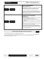
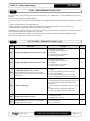
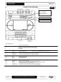
CONNECTION DIAGRAM
A.2
LED DL8: board status
OFF = POWER OFF
BLINK = board OK,
FAST Blink = board alarm
Echo display connection
Primary display connection
Power supply section
1-2:
230 Vac 50/60Hz power supply
Section of EEV electronic valve
3:
4:
5:
(230Vac) (J2 internal bridge set between 1-2)
PWM output for control of EEV electronic valve at 230Vac
PWM output for control of EEV electronic valve at 230Vac
NOT USED
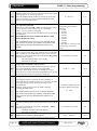
Section of digital outputs (voltage-free contacts)
6-7:
(DO3)
Configurable relay / Alarm
TeleNet section
18:
19:
(RS485-A2)
(RS485-A2)
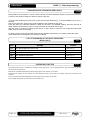
Section of digital inputs
23:
(DI2)
24:
(DI2)
25:
(COM DI)
Section of analogue inputs
26:
(COM AN gnd)
27:
(AN_4)
28:
(AN_5)
29:
30:
Page 22
(COM AN +5V)
(COM AN +12V)
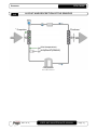
[ RELAY
8A ] Brand: SCHRACK ; Code: RY211012
To terminal 4 of the RS485 interface for TeleNet – Modbus-RTU
To terminal 3 of the RS485 interface for TeleNet – Modbus-RTU
Configurable digital input 2
Configurable digital input 1
Common digital inputs
Common analogue sensors (gnd)
Input NTC sensor (S4). [Temperature of superheated gas for EEV].
Evaporation pressure sensor (S5) [x EEV] (4-20mA analogue input with closed J1 /
0-5V x ratiometric pressure sensor with open J1 )
+5V (ratiometric sensor power supply, to be used only with open J1 )
+12V (4-20mA sensor power supply, to be used only with closed J1)
USER AND MAINTENANCE MANUAL
Rev. 01-14