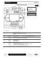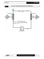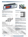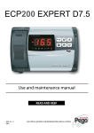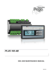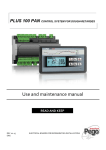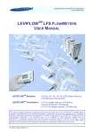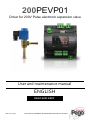
1
200PEVP01 Driver for 230V Pulse electronic expansion valve User and maintenance manual ENGLISH READ AND KEEP REV. 01-14 EN ELECTRICAL BOARDS FOR REFRIGERATING INSTALLATIONS PEV PULSE Contents CONTENTS INTRODUCTION Page Page Page Page 3 3 4 4 1.1 1.2 1.3 1.4 CHAP. 1 General Product identification codes Overall dimensions Identification data INSTALLATION Page 5 Page 5 Page 6 2.1 2.2 2.3 CHAP. 2 General rules for the installer Standard equipment for assembly and use Installation of the board TECHNICAL FEATURES Page 7 3.1 CHAP. 3 Technical features TERMS OF THE GUARANTEE Page 8 4.1 CHAP. 4 Terms of the guarantee DATA PROGRAMMING Page Page Page Page Page Page Page Page Page Page Page Page 9 9 10 10 11 12 12 13 13 17 17 17 5.1 5.2 5.3 5.4 5.5 5.6 5.7 5.8 5.9 5.10 5.11 5.12 Control panel Front keypad LED display Combination of keys Setting and viewing of ESH set points Level 1 programming List of Level 1 variables Level 2 programming List of Level 2 variables Variable quick view menu (read-only) List of variables in variable quick view menu (read-only) Password function 6.1 6.2 TelNET monitoring/supervision system Network configuration with Modbus-RTU protocol OPTIONS Page 18 Page 18 DIAGNOSTICS Page 19 7.1 Page 2 A.1 A.2 A.3 CE Declaration of Conformity Connection diagram Layout and description of sensors USER AND MAINTENANCE MANUAL CHAP. 6 CHAP. 7 Diagnostics ANNEXES Page 20 Page 21 Page 22 CHAP. 5 Rev. 01-14 CHAP. 1 - Introduction PEV PULSE CHAPTER 1: INTRODUCTION GENERAL 1.1 DESCRIPTION The PEV PULSE is anelectronic regulator for controlling the 230 VAC ON/OFF electronic expansion valve with coil. It can be configured on either the remote display or the integrated display. It is compatible with the most common 230VAC ON/OFF electronic expansion valves and integrates evaporator superheat control. APPLICATIONS: - Refrigerated counters and cold rooms. MAIN FEATURES: - Control of the 230VAC ON/OFF electronic expansion valve with coil. Integrated or remote control console. - RS485 serial connection with TeleNET or Modbus protocol which can be selected in the parameters. - Two configurable digital inputs. - Inlet temperature and evaporation pressure sensor for evaporator superheat control. - Remote display with IP65 protection. - Easy programming of parameters with 4 pre-settings for the various applications of the electronic expansion valve. - Alarm signalling. - LED status signals and large display screen. - Userfriendly keypad. PRODUCT IDENTIFICATION CODES 200PEVP01 1.2 Electronic regulator for control of the electronic expansion valve. It can be configured on either the remote display or the integrated display. It is compatible with the most common 230VAC ON/OFF electronic expansion valves. Evaporator superheat control. Rev. 01-14 USER AND MAINTENANCE MANUAL Page 3 PEV PULSEContents 1.3 CHAP. 1 - Introduction OVERALL DIMENSIONS Dimensions in mm. 1.4 IDENTIFICATION DATA The device described in this manual has a plate on one side bearing the identification data: • Name of Manufacturer • Code and model of the electrical board of the device • Serial number • Date of manufacture CHAP. 2 - Installation PEV PULSE CHAPTER 2: INSTALLATION GENERAL RULES FOR THE INSTALLER 2.1 1. Install the device in an area that ensures the correct degree of protection, and take all due care when drilling holes in the box for the cable glands and/or hoses. 2. Avoid using multi-pole cables with conductors connected to inductive and power conductors and signal conductors like sensors and digital inputs. 3. Avoid inserting ducts and power cables with signal cables (sensors and digital inputs) in these. 4. Minimize the length of the connecting cables to prevent these from coiling up and adversely affecting the electronics through induction. 5. All the conductors of the cables must be of an appropriate size to withstand the required load. 6. When extensions are needed for the sensors, it is necessary to use conductors of a suitable size measuring no less than 1 mm². Extension or shortening of the sensors may alter the factory settings; use an external thermometer, therefore, for testing and calibration. STANDARD EQUIPMENT FOR ASSEMBLY AND USE 2.2 The PEV PULSE electronic controller is provided with the following for assembly and use: • 1 x user manual. Rev. 01-14 USER AND MAINTENANCE MANUAL Page 5 PEV PULSEContents 2.3 CHAP. 2 - Installation INSTALLATION OF BOARD Fig. 1: Install the module on the DIN guide and close the bottom clamp to hold it in place. Make all the electrical connections with reference to the diagrams of the relative model (see the relative tables in the ANNEXES). During the cabling process, it is advisable to keep the power conductors isolated from the signal conductors. Page 6 USER AND MAINTENANCE MANUAL Rev. 01-14 CHAP.3 – Technical features PEV PULSE CHAPTER 3: TECHNICAL FEATURES TECHNICAL FEATURES 3.1 Power supply Voltage Max power consumption (electronic control only) 230 V~ 10% 50Hz / 60Hz ~ 7 VA Climatic conditions Operating temperature -5 to +50°C Storage temperature -10 to +70°C Relative ambient humidity Less than 90% RH General features Compatible types of temperature sensor Temperature sensors: NTC 10K 1% Resolution of temperature sensors 0.1 °C Precision of temperature sensor detection ± 0.5 °C Range of temperature sensor detection -45 to +45 °C Compatible type of pressure sensor: pressure sensor: 4/20mA / radiometric 0-5V Output features Description Alarm (voltage-free contact) Pulse valve Relay installed Features of output board (8A AC1 relay) 8(3)A 250V~ triac 50VA (pulse valve) Notes Dimensional features Dimensions 12.15cm x 7.1cm x 10.5cm (HxWxL) Dimensions (console/echo) 3.7cm x 2.31cm x 9.3cm (HxWxL) Insulation and mechanical properties Degree of protection of front console (remotecontrolled by the power section if assembled on front of board) Material of boxes Type of insulation IP65 PC+ABS self-extinguishing UL94 V-0 Class II Conformity to EU standards (low voltage directive), EMC compatibility and CE marking It conforms to the following EC directives: Directives 2004/108/EC, 2006/95/EC It conforms to the following harmonized standards: EN60335-1, EN378-1:2003, EN61000-6-1, EN61000-6-3 Rev. 01-14 USER AND MAINTENANCE MANUAL Page 7 CHAP. 4 – Terms of the guarantee PEV PULSE 4.1 TERMS OF THE GUARANTEE The PEV PULSE electronic controls are guaranteed against all manufacturing defects for 24 months from the date in the production identification code or the date on the product registration card, when applicable. In the event of defects, the device must be returned properly packaged to our Site or authorized assistance centre after requesting and receiving the authorization number for returning the product. The Customer has the right to repair the defective device inclusive of manual labour and spare parts. The Customer assumes sole responsibility for the expenses and the risks associated with transport. All work carried out under the terms of the guarantee does not renew or extend the duration of the guarantee. The guarantee does not cover: Damage attributable to tampering, negligence, carelessness or inadequate installation of the device. Installation, use or maintenance not in compliance with the rules and instructions provided with the device. Repairs carried out by unauthorized personnel. Damage attributable to natural causes like lightning, natural disasters, etc. In all the above cases, the customer pays for the cost of repair. Request for repairs under the terms of the guarantee may be refused if the device has been modified or converted. PEGO S.r.l. cannot assume responsibility for any loss of data or information, the cost of replacement goods or services, injury to people or animals, loss of sales or earnings, downtime, and any direct, indirect, accidental, pecuniary, collateral, punitive, special or consequential damage or loss caused in any way, within or outside the scope of the contract or due to negligence or other responsibilities associated with use or installation of the product. The guarantee is terminated automatically in the event of poor operation attributable to tampering, collisions and inadequate installation. It is obligatory to observe all the rules in this manual and the operating conditions of the device. PEGO S.r.l. cannot assume any responsibility for inaccuracies in this manual attributable to printing or transcription errors. PEGO S.r.l. reserves the right to make changes to its products that it considers necessary or useful without affecting their essential characteristics. Each new release of the manuals for PEGO's products replaces all previous releases. Unless specified otherwise, the guarantee is governed by the rules in force and, in particular, article 1512 of the Italian Civil Code. All disputes are settled at the Court of Rovigo. Page 8 USER AND MAINTENANCE MANUAL Rev. 01-14 CHAP. 5 – Data programming PEV PULSE CHAPTER 5: DATA PROGRAMMING CONTROL PANEL 5.1 FRONT KEYPAD UP KEY DOWN KEY STAND BY 5.2 Increases value / Scrolls up through parameters Turns off auditory alarm in progress / Acquires an alarm. Decreases value / Scrolls down through parameters. THE PEV-PULSE CAN BE PAUSED NOT BY PRESSING THE KEY BUT BY DISABLING IT AT THE DIGITAL INPUT OR LAN. Rev. 01-14 USER AND MAINTENANCE MANUAL Page 9 CHAP. 5 – Data programming PEV PULSE SET Page 10 Shows the setpoint Enables configuration of the SUPERHEAT setpoint when pressed together with the Down or UP key. Resets an auditory alarm in progress. USER AND MAINTENANCE MANUAL Rev. 01-14 CHAP. 5 – Data programming PEV PULSE LED DISPLAY 5.3 Shows the values / parameters. DEFROSTING ICON EEV OUTPUT STATUS ICON Output status of the EEV electronic valve "PRG" ICON LED OFF = Defrosting input OFF LED ON = Defrosting input ON LED OFF = EEV output OFF LED ON = EEV output ON Blinking LED = Programming ALARM IN PROGRESS ICON LED OFF = No alarm in progress LED ON = Alarm triggered and then cancelled Blinking LED = Alarm in progress COMBINATION OF KEYS 5.4 EXIT PROGRAMMING + Pressing both keys together for over 3 seconds in any programming menu saves all changes made and exits the menu concerned. A beep is emitted when the system closes the menu. LEVEL 1 PROGRAMMING + Rev. 01-14 + Pressing both keys together for more than 3 seconds enables access to the Level 2 programming menu. A beep is emitted when the system opens the menu. To exit the menu, press the up and down arrow keys together (the system beeps to confirm). Alternatively, the system closes the menu automatically when the keypad is not used for 30 seconds. USER AND MAINTENANCE MANUAL Page 11 CHAP. 5 – Data programming PEV PULSE LEVEL 2 PROGRAMMING (EEV parameters) + Pressing both keys together for more than 3 seconds enables access to the Level 3 programming menu. The system beeps to confirm access to the menu. To exit the menu, press the up and down arrow keys together (the system beeps to confirm). Alternatively, the system closes the menu automatically when the keypad is not used for 30 seconds. VARIABLE QUICK VIEW MENU (READ-ONLY) + Pressing both together for more than 3 seconds enables access to the variable quick view menu. The system beeps to confirm access to the menu. Use the Up and Down arrow keys to view the labels of the variables. Press the Set key to alternate between a label and its value. With the value of a label on display, press the up or down arrow to view the next or previous label. To exit the menu, press the up and down arrow keys together (the system beeps to confirm). Alternatively, the system closes the menu automatically when the keypad is not used for 30 seconds. VIEWING AND CONFIGURATION OF ESH SETPOINT 5.5 1. Press the SET key to view the current SETPOINT value (ESH). 2. Pressing and holding the SET key and pressing one of the keys ( ) or () alters the value of the ESH SETPOINT. Release the SET key to return to the ESH temperature. Any changes made are saved automatically. Range of the ESH SETPOINT: 0.1 – 25°C. Page 12 USER AND MAINTENANCE MANUAL Rev. 01-14 CHAP. 5 – Data programming PEV PULSE LEVEL 1 PROGRAMMING (Installer level) 5.6 To access Level 2 programming, press and hold the UP key ( ), DOWN key () and STAND-BY key for over 3 seconds. When the first programming variable appears. 1. Use the () key or () key to select the variable to be modified. After selecting the required variable, it is possible to: 2. View its configuration by pressing the SET key. 3. Edit configuration by pressing and holding the SET key and pressing either the ( ) key or the () key. 4. After setting the configuration values, exit the menu by pressing and holding, for several seconds, keys () and () until the room temperature value appears. The system closes the menu when the keypad is not used for over 30 seconds. 5. Any changes made to the variables are saved automatically when the system closes the configuration menu. Valve control continues even when the menu is open. LIST OF LEVEL 1 VARIABLES (Installer Level) 5.7 VARIA BLES MEANING DEFA ULT VALUES Setting of DI1 digital input and activation status 2= Defrosting (with DI=1) 1= ON EEV Driver (with DI=1) 0= Disabled -1= ON EEV Driver (with DI=0) -2= Defrosting (with DI=0) 1 In2 Setting of DI2 digital input and activation status 2= Defrosting (with DI=1) 1= ON EEV Driver (with DI=1) 0= Disabled -1= ON EEV Driver (with DI=0) -2= Defrosting (with DI=0) 0 D03 Setting use of DO3 digital output. Configurable auxiliary relay / Alarm Note: Solenoid valve control involves a normal solenoid valve, and the output repeats the ON input of the Driver. 2 = DO5 relay enabled with solenoid valve control 1 = DO5 relay enabled in presence of alarm 0 = DO5 relay disabled -1 = DO5 relay disabled in presence of alarm -2 = DO5 disabled with solenoid valve control 1 dIS Viewing of main page 1 = (tS4) Viewing of Inlet temperature sensor (S4) 2 = (tS5) Viewing of Evaporation temperature sensor (S5) 3 = (PS5) Viewing of Evaporation pressure sensor (S5) 4 = (tSH) Viewing of Superheat temperature 5 = (oEV) Opening percentage of EEV valve 4 SEr RS-485 communication protocol 0 = TeleNET protocol 1 = Modbus-RTU protocol Ad Network address for connection to the TeleNET or Modbus supervision system 0 to 31 (with SEr=0) 1 to 247 (with SEr=1) In1 Rev. 01-14 USER AND MAINTENANCE MANUAL 0 0 Page 13 CHAP. 5 – Data programming PEV PULSE P1 Password: type of protection (active when PA is not at 0) 0 = shows only the setpoint and permits deactivation of the alarms . 1 = shows the setpoint, permits deactivation of the alarms + access to the read-only variable menu 3 2 = disables access to level 1 and 2 programming (access permitted to all other functions) 3 = disables access to level 2 programming (access permitted to all other functions) PA Password (see P1 for the type of protection) reL Software release 0...999 0 = function disabled 0 read-only readonly LEVEL 2 PROGRAMMING (EEV parameters) 5.8 To access Level 2 programming, press and hold the UP key () and STANDBY key for over 3 seconds. When the first programming variable appears. 1. Use the () key or () key to select the variable to be modified. After selecting the required variable, it is possible to: 2. Visualizzarne l’impostazione premendo il tasto SET. 3. Edit configuration by pressing and holding the SET key and pressing either the ( ) key or the () key. 4. After setting the configuration values, press and hold both the ( ) key and the () key to return to the room temperature value and exit the menu. The system exits the menu when the keypad is not used in 30 seconds. 5. Any changes made to the variables are saved automatically when the system closes the configuration menu. Valve control continues even when the menu is open. LIST OF LEVEL 2 VARIABLES (EEV parameters) VARIA BLES MEANING EEV Management of the EEV electronic valve With EEV=0 all the controls and relative signals are disabled. The relative errors of the S4 sensors (outlet temperature) and S5 sensors (evaporation pressure) are also disabled and excluded. Settings 1 to 4 load the default values of the variables ECt, EPb, EtI, Etd, ELS After exiting the programming process the default values are loaded if the value of the EEV differs from the one saved previously. Pressing just the Set key to view the current EEV value does not load the default values. ErE Type of refrigerant GAS in use. The setting of this parameter is essential for correct operation. Page 14 USER AND MAINTENANCE MANUAL VALUES 1 = EEV control (default 1) 2 = EEV control (default 2) 3 = EEV control (default 3) 4 = EEV control (default 4) 5 = EEV control (default 5) 0 = 404 1 = 134 2 = R22 3 = 407 4 = 410 5 = 507 6 = CO2 5.9 DEFAULT 1 0 Rev. 01-14 CHAP. 5 – Data programming ECt PEV PULSE Cycle time This represents the sum of the timers of an EEV valve opening/closing cycle. The opening and closing timers of the EEV are calculated on this basis. 1-20 sec 6 sec 15% Example: if the EEV valve has to be opened by 30%: EEV valve opening timer = ECt* 30/100 EEV valve closing timer = ECt * (100-30)/100 EPb Proportional band (gain) superheat control PID. 1...100% EtI Integral timer superheat PID control algorithm 0-500 sec steps of 2 sec. 100 sec Etd Derivative timer superheat PID control algorithm 0,0 -10,0 sec steps of 0,1 sec. 2,0 sec EOE EEV valve opening percentage in event of error with S4 or S5 sensors. This function permits (diminished) control in the event of a fault with one of the control sensors. 0...100% 50% ESO During the Start-up phase, the EEV valve opens by the ESO percentage for the ESt time. 0...100% 85% ESt EdO Edt EHO Duration of the Start-up phase. The superheat alarms are disabled during this phase. The MOP, LOP and LSH alarms are disabled during this phase. After defrost, the EEV valve opens by the EdO percentage for the Edt time. 6 tenths of a second 0-Edt in tenths of a second 0...100% Duration of EdO valve opening phase after defrost. The superheat alarms are disabled during this phase. The MOP, LOP and LSH alarms are disabled during this phase. ESt-250 tenths of a second. Maximum opening percentage of EEV valve. In the case of an oversize valve, this variable permits limitation of maximum opening of the valve at a set percentage. 0...100% 100% 24 tenths of a second 100% 0= 4-20mA pressure transducer connected to the instrument EPP Type of pressure transducer (S5): Sets the type of transducer for detecting the Evaporation pressure (S5) EP4 Pressure (bar) corresponding to 4mA or 0V. In relation to the Evaporation pressure sensor (S5) (-1.0 - EP2 bar) (EP4 is always <24.5) 0.0 EP2 Pressure (bar) corresponding to 20mA or 5V. In relation to the Evaporation pressure sensor (S5) (EP4 - 50.0 bar) steps of 0.2(EP2 is always >0) 12.0 CA4 Calibration of the inlet temperature transducer -10.0…+10.0 °C 0.0 CA5 Calibration of the Evaporation pressure transducer (S5) -10.0…+10.0 Bar 0.0 Rev. 01-14 1 = 0-5V ratiometric pressure transducer connected to the instrument USER AND MAINTENANCE MANUAL 0 Page 15 PEV PULSE LSH ELS LSH threshold (low superheat temperature) Superheat values that are too low can cause return of the liquid to the compressor, or extreme oscillations. Below the LSH threshold, the ELS protection forces the PID control to close the valve more quickly and bring the value back up to the superheat setpoint. Low superheat protection When this is enabled and SH < LSH, the PID integration timer is set on the basis of the selection of 1 to 7 of the ELS. Value 1 is for the quickest closing time. Enabling of this protection starts the SHd counter for activating the LSH alarm. THE LSH PROTECTION TAKES PRIORITY OVER THE LOP PROTECTION. THE LSH PROTECTION IS NOT ACTIVATED DURING THE START-UP PHASE (ESt TIMER) OR DURING THE DEFROSTING OR POST-DEFROSTING PHASE (Edt TIMER) SHd MOP EMO MOd LOP Activation delay of the superheat alarm: the LSH superheat alarm is triggered only after it has remained active for the SHd time. In the event of an LSH alarm, the valve closes instantly; The alarm is automatically reset and recalled when SH ≥ LSH When the alarm is active: - The LSH message blinks on the display - The buzzer is activated MOP threshold (Maximum Saturated Evaporation Temperature in relation to the S5 sensor) This represents the maximum saturated evaporation pressure above which the MOP protection is activated (EMO parameter). When MOP protection is enabled, the control closes the valve to limit evaporation temperature and to prevent the thermal protection from stopping the compressor. MOP protection (enabled when tS5>MOP) CHAP. 5 – Data programming 0... SH set °C 2 °C 0 = disables the LSH protection and signalling of the relative LSH alarm 1= 5% EtI 2= 10% EtI 3= 15% EtI 4= 20% EtI 5= 25% EtI 6= 30% EtI 7= 35% EtI 8= 50% EtI 9= 100% EtI (no correction, and activation only of the LSH alarm) 2 0 - 240 tenths of a second 30 (LOP+1) ...+45°C +45°C When MOP protection is enabled, the valve abandons its control PID and, for each stage of the cycle, closes by the EMO percentage starting from the opening percentage of the abandoned PID. 0 = disables the MOP protection Enabling of this protection starts the MOd counter for and relative MOP alarm signal activating the MOP alarm. 0…100% THE MOP PROTECTION IS NOT ENABLED DURING THE START-UP PHASE (ESt TIMER) OR DURING THE DEFROSTING OR POST-DEFROSTING PHASE (Edt TIMER). MOP alarm activation delay: the MOP alarm is triggered only after the MOP protection has remained active for the MOd time. The alarm is automatically reset when "Temp.S5" ≤ MOP When the alarm is active: - The MOP message blinks on the display - The buzzer is activated LOP threshold (minimum saturated evaporation temperature in relation to the S5 sensor) This represents the minimum saturated evaporation pressure Page 16 USER AND MAINTENANCE MANUAL 0 0 - 240 tenths of a second 60 -45°C .. (MOP-1) -45°C Rev. 01-14 CHAP. 5 – Data programming PEV PULSE below which the LOP protection is activated. When LOP protection is enabled, the control opens to prevent the compressor from stopping due to low pressure (mechanical pressure switch). LOP protection (activated when tS5<LOP) ELO LOd When LOP protection is enabled, the valve abandons its control PID and, for each stage of the cycle, opens by the ELO percentage starting from the opening percentage of the abandoned PID. 0 = disables the LOP protection Enabling of this protection starts the LOd counter for activating and relative LOP alarm signal the LOP alarm. THE LSH PROTECTION TAKES PRIORITY OVER THE 0…100% LOP PROTECTION. THE LOP PROTECTION IS NOT ENABLED DURING THE START-UP PHASE (ESt TIMER) OR DURING THE DEFROSTING OR POST-DEFROSTING PHASE (Edt TIMER). Activation delay of the LOP alarm: the LOP alarm is triggered only after it has remained active for the LOd time. In the event of an LOP alarm: The alarm is automatically reset when"Temp.S5" ≥ LOP When the alarm is active: - The LOP message blinks on the display - The buzzer is activated 0 - 240 tenths of a second 0 30 Note: all the calculation times of the LSH, MOP and LOP are reset when the control stops OR DURING THE START PHASE (ESt TIMER) OR DURING THE DEFROSTING OR POST-DEFROSTING PHASE (Edt TIMER). Loading of default settings on the basis of the EEV variable: EEV = 2 EEV = 3 EEV = 1 (ROOM or TN (ROOM or BT PEGO DEFAULT REFRIGERATED REFRIGERATED COUNTER control COUNTER control with on-board with on-board compressor) compressor) 6 °C 6 °C 6 °C ESH 15 % 15 % 15 % EPb 100 sec 100 sec 100 sec EtI 2,0 sec 2,0 sec 2,0 sec Etd 2 °C 2 °C 2 °C LSH 2 2 2 ELS +45 °C 5 °C -15 °C MOP 0 5 5 EMO -45 °C -25 °C -45 °C LOP 0 15 15 ELO Rev. 01-14 EEV = 4 (ROOM or DUCTED TN REFRIGERATED COUNTER control) 11 °C 15 % 150 sec 5,0 sec 5 °C 2 +5 °C 5 0 0 USER AND MAINTENANCE MANUAL EEV = 4 (ROOM or DUCTED BT REFRIGERATED COUNTER control) 11 °C 15 % 150 sec 5,0 sec 5 °C 2 -15 °C 5 0 0 Page 17 CHAP. 5 – Data programming PEV PULSE VARIABLE QUICK VIEW MENU (READ-ONLY) 5.10 During start-up of the system, it can be useful to quickly check the detection efficiency of the various sensors or some of the values to assess or improve upon the process. To access the variable quick view menu, press and hold the DOWN key ( ) and STANDBY key for over 3 seconds. Use the Up and Down arrow keys to view the labels of the variables in this menu. Press the Set key to alternate between a label and its value. (To facilitate reading, press the Set key to switch between a label and its value. It is not necessary to hold down the set key). With the value of a label on display, press the up or down arrow to view the next or previous label (and switch from the value to the label) To exit the menu, press the up and down arrow keys together. Alternatively, the system closes the menu automatically when the keypad is not used for 2 minutes. LIST OF VARIABLES IN THE QUICK VIEW MENU (READ-ONLY) VARIA BLES 5.11 MEANING VALUES tS4 View Inlet Temperature sensor (S4) (read-only) °C tS5 View Evaporation Temperature sensor (S5) (read-only) °C PS5 View Evaporation Pressure sensor (S5) (read-only) Bar tSH View superheat temperature (read-only) °C oEV EEV valve opening percentage (read-only) % PASSWORD FUNCTION 5.12 The password function is enabled by setting a value other than 0 in the PA parameter. See parameter P1 for the various levels of protection. Protection is enabled automatically when the keypad is not used for 30 seconds. The digits 000 appear on the display. Use the up/down arrow keys to edit the number and press the SET key to confirm. The 000 password window disappears if the keypad is not used for 30 seconds. If you forget the password, use the universal number 100. Page 18 USER AND MAINTENANCE MANUAL Rev. 01-14 CHAP. 6 – Options PEV PULSE CHAPTER 6: OPTIONS 6.1 TELENET MONITORING/SUPERVISION SYSTEM In order to connect the board to the TeleNET network, follow the diagram below. Configure the 1 instrument with reference to the TeleNET manual. IMPORTANT: During configuration of the “Module”, select " PEV-PULSE instrument ". 6.2 CONFIGURATION OF NETWORK WITH MODBUS-RTU PROTOCOL Connect the board to a RS485 network with Modbus-RTU protocol with reference to the diagram below. Refer to the MODBUS-RTU_PEV_PULSE manual (available on our website) for the specifications of the MODBUS-RTU communication protocol. Rev. 01-14 USER AND MAINTENANCE MANUAL Page 19 CHAP. 7 – Diagnostics PEV PULSE CHAPTER 7: DIAGNOSTICS DIAGNOSTICS 7.1 In the event of a fault, the PEV PULSE controller displays alarm codes on the screen and triggers the buzzer (when applicable). The auditory alarm can be stopped by pressing the UP key (the error code remains) and reactivated by pressing the SET key. One of the following messages appears on the screen when an alarm condition occurs: ALARM CODE POSSIBLE CAUSE E4 Functional fault of the S4 inlet temperature sensor E5 Functional fault of the Evaporation pressure sensor (S5) LSH Low superheat alarm MOP Alarm for maximum saturated evaporation temperature exceeded, in relation to sensor S5 LOP Alarm for minimum saturated evaporation temperature exceeded, in relation to sensor S5 ACTION TO BE TAKEN Check the condition of the sensor and its connections If the problem persists, replace the sensor Check the condition of the sensor and its connections If the problem persists, replace the sensor En Connection between display and unit interrupted automatic EE EEPROM alarm An error was found in the EEPROM memory. (The outputs are all disabled apart from the alarm outputs, if configured) requires reactivation of the board Page 20 USER AND MAINTENANCE MANUAL Rev. 01-14 Annexes PEV PULSE ANNEXES CE DECLARATION OF CONFORMITY A.1 COSTRUTTORE: MANUFACTURER: PEGO S.r.l. Via Piacentina, 6/b 45030 Occhiobello (RO) – Italy – Tel. (+39) 0425 762906 Fax. (+39) 0425 762905 DENOMINAZIONE DEL PRODOTTO: NAME OF THE PRODUCT: MOD.: 200PEVP01 (PEV PULSE) IL PRODOTTO E’ CONFORME ALLE SEGUENTI DIRETTIVE CE: THE PRODUCT IS IN CONFORMITY WITH THE REQUIREMENTS OF THE FOLLOWING EUROPEAN DIRECTIVES: Direttiva Bassa Tensione (LVD): Low voltage directive (LVD): 2006/95/CE EC/2006/95 Direttiva EMC: Electromagnetic compatibility (EMC): 2004/108/CE EC/2004/108 LA CONFORMITA’ PRESCRITTA DALLA DIRETTIVA E’ GARANTITA DALL’ADEMPIMENTO A TUTTI GLI EFFETTI DELLE SEGUENTI NORME (comprese tutte le modifiche): THE CONFORMITY WITH THE REQUIREMENTS OF THIS DIRECTIVE IS TESTIFIED BY COMPLETE ADHERENCE TO THE FOLLOWING STANDARDS (including all amendments): Norme armonizzate: European standards: EN 60335-1, EN 378-1:2003, EN 61000-6–1, EN 61000-6–3 EN60335-1, EN 378-1:2003, EN 61000-6–1, EN 61000-6–3 IL PRODOTTO E’ COSTITUITO PER ESSERE INCORPORATO IN UNA MACCHINA O PER ESSERE ASSEMBLATO CON ALTRI MACCHINARI PER COSTITUIRE UNA MACCHINA CONSIDERATE DALLA DIRETTIVA: 2006/42/CE “Direttiva Macchine”. THE PRODUCT HAS BEEN MANUFACTURED TO BE INCLUDED IN A MACHINE OR TO BE ASSEMBLED TOGETHER WITH OTHER MACHINERY TO COMPLETE A MACHINE ACCORDING TO DIRECTIVE: EC/2006/42 “Machinery Directive”. Occhiobello (RO), 01/08/2011 Rev. 01-14 USER AND MAINTENANCE MANUAL Page 21 PEV PULSE Annexes CONNECTION DIAGRAM A.2 LED DL8: board status OFF = POWER OFF BLINK = board OK, FAST Blink = board alarm Echo display connection Primary display connection Power supply section 1-2: 230 Vac 50/60Hz power supply Section of EEV electronic valve 3: 4: 5: (230Vac) (J2 internal bridge set between 1-2) PWM output for control of EEV electronic valve at 230Vac PWM output for control of EEV electronic valve at 230Vac NOT USED Section of digital outputs (voltage-free contacts) 6-7: (DO3) Configurable relay / Alarm TeleNet section 18: 19: (RS485-A2) (RS485-A2) Section of digital inputs 23: (DI2) 24: (DI2) 25: (COM DI) Section of analogue inputs 26: (COM AN gnd) 27: (AN_4) 28: (AN_5) 29: 30: Page 22 (COM AN +5V) (COM AN +12V) [ RELAY 8A ] Brand: SCHRACK ; Code: RY211012 To terminal 4 of the RS485 interface for TeleNet – Modbus-RTU To terminal 3 of the RS485 interface for TeleNet – Modbus-RTU Configurable digital input 2 Configurable digital input 1 Common digital inputs Common analogue sensors (gnd) Input NTC sensor (S4). [Temperature of superheated gas for EEV]. Evaporation pressure sensor (S5) [x EEV] (4-20mA analogue input with closed J1 / 0-5V x ratiometric pressure sensor with open J1 ) +5V (ratiometric sensor power supply, to be used only with open J1 ) +12V (4-20mA sensor power supply, to be used only with closed J1) USER AND MAINTENANCE MANUAL Rev. 01-14 Annexes A.3 PEV PULSE LAYOUT AND DESCRIPTION OF THE SENSORS Evaporator Condenser (Inlet temperature) (Evaporation pressure) Compressor Rev. 01-14 USER AND MAINTENANCE MANUAL Page 23 PEV PULSE Annexes PEGO S.r.l. Via Piacentina, 6/b Agent: 45030 OCCHIOBELLO –ROVIGOTel : (+39) 0425 762906 Fax: (+39) 0425 762905 www.pego.it USER AND MAINTENANCE MANUAL Page 24 e-mail: [email protected] Rev. 01-14