1
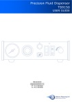
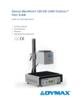
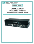
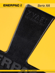
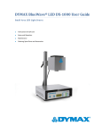
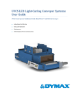
Low-Level Sensing Systems User Guide Cartridge Reservoirs or Bottle Drop-In Tanks with Low-Level Sensor Systems Instructions for Safe Use Setup and Operation Maintenance Ordering Spare Parts and Accessories 2 Dymax Low-Level Sensing Systems User Guide About Dymax UV/Visible light-curable adhesives. Systems for light curing, fluid dispensing, and fluid packaging. Dymax manufactures industrial adhesives, light-curable adhesives, epoxy resins, cyanoacrylates, and activator-cured adhesives. We also manufacture a complete line of manual fluid dispensing systems, automatic fluid dispensing systems, and light-curing systems. Light-curing systems include LED light sources, spot, flood, and conveyor systems designed for compatibility and high performance with Dymax adhesives. Dymax adhesives and light-curing systems optimize the speed of automated assembly, allow for 100% in-line inspection, and increase throughput. System designs enable stand-alone configuration or integration into your existing assembly line. Please note that most dispensing and curing system applications are unique. Dymax does not warrant the fitness of the product for the intended application. Any warranty applicable to the product, its application and use is strictly limited to that contained in the Dymax standard Conditions of Sale. Dymax recommends that any intended application be evaluated and tested by the user to insure that desired performance criteria are satisfied. Dymax is willing to assist users in their performance testing and evaluation. Data sheets are available for valve controllers or pressure pots upon request. Dymax Low-Level Sensing Systems User Guide Contents Introduction .................................................................................................................................................... 4 Introduction to the User Guide ....................................................................................................................................... 4 Where to Get Help .......................................................................................................................................................... 4 Safety.............................................................................................................................................................. 4 General Safety Considerations ........................................................................................................................................ 4 Specific Safety Considerations ......................................................................................................................................... 5 Bottle Drop-In Tank Potential Hazards ............................................................................................................................ 5 Product Overview ........................................................................................................................................... 8 Description of the Dymax Low-Level Sensing System ..................................................................................................... 8 Utilities Required ............................................................................................................................................................. 8 Main System Components .............................................................................................................................................. 9 Unpacking ..................................................................................................................................................... 12 Unpacking and Inspecting Your Shipment ..................................................................................................................... 12 Parts Included with Cartridge Reservoir Systems .......................................................................................................... 12 Parts Included with 1-Gallon Reservoir Systems ........................................................................................................... 12 Sensor Set Up & Operation - Cartridge Reservoir Systems ................................................................... 12 Setting the Sensor Indication Level ............................................................................................................................... 12 Replacing the Cartridge Reservoir ................................................................................................................................. 14 Sensor Set Up & Operation – Bottle Drop-In Reservoir Systems .......................................................... 14 Connecting Air Regulators and Material Line to the Tank Cover ................................................................................... 15 Connecting Material Outlet Tube .................................................................................................................................. 15 Installing Pressure Plate Sensor Assembly .................................................................................................................... 16 Setting Low-Level Indication Level ................................................................................................................................ 17 Inserting the Bottle Reservoir in the Tank ..................................................................................................................... 18 SB-100 Controller Setup ................................................................................................................................ 19 Connecting the Sensor to the SB-100 Controller ........................................................................................................... 19 SB-100 Function Options ............................................................................................................................................... 20 Cleaning & Maintenance ............................................................................................................................... 22 System Cleaning ............................................................................................................................................................ 22 Periodic Sensor Maintenance ........................................................................................................................................ 22 Troubleshooting............................................................................................................................................ 23 Spare Parts and Accessories .......................................................................................................................... 24 Spare/Replacements Parts ............................................................................................................................................ 24 Specifications ................................................................................................................................................ 25 System Specifications .................................................................................................................................................... 25 Warranty ...................................................................................................................................................... 26 Index ............................................................................................................................................................. 27 3 4 Dymax Low-Level Sensing Systems User Guide Introduction Introduction to the User Guide This guide describes how to use Dymax Low-Level Sensing Systems. Sections in this guide describe how to assemble, use, and maintain the equipment safely and efficiently. Intended Audience Dymax prepared this user guide for experienced process engineers, technicians, and manufacturing personnel. If you do not understand the instructions, contact Dymax Application Engineering to answer your questions before using the equipment. Where to Get Help Additional resources are available to ensure a trouble-free experience with our products: Detailed product information on www.dymax.com Dymax Customer Support and Application Engineering teams are available in the United States, Monday through Friday, from 8:00 a.m. to 5:30 p.m. Eastern Standard Time. You can also email Dymax at [email protected]. Contact information for additional Dymax locations can be found on the back cover of this user guide. Dymax adhesive Product Data Sheets (PDS) on our website Material Safety Data Sheets (MSDS) provided with shipments of Dymax adhesives Safety WARNING! If you use this equipment without first reading and understanding the information in this guide, personal injury can result from the uncontrolled release of highpressure gas, injection, or exposure to chemicals. To reduce the risk of injury, read and understand this guide before assembling and using the Dymax fluid dispensing system. General Safety Considerations All users of Dymax equipment systems should read and understand this user guide before assembling and using the system. To learn about the safe handling and use of dispensing fluids, obtain and read the Material Safety Data Sheet and handling requirements for each fluid before using the fluid. Dymax includes a Material Data Safety Sheet with each adhesive we sell. You can also request Material Safety Data Sheets for our products on our website. Dymax Low-Level Sensing Systems User Guide Specific Safety Considerations Using Safe Operating Pressures Pressurizing the components in the dispensing system beyond the maximum recommended pressure can result in the rupturing of components and serious personal injury. To minimize the risk of rupturing components and injury, do not exceed the maximum operating pressure of the components in your fluid dispensing system. (See system specifications) Replacing System Parts When replacing system parts, ensure the quality of replacement parts matches the quality of the original equipment parts to maintain the safety and operational performance of the system. Bottle Drop-In Tank Potential Hazards Equipment Misuse WARNINGS! This equipment is for professional use only. Serious injury can result from highpressure fluids. To reduce the risk of injury, read and ensure you understand the information in this user guide before assembling and operating the Dymax pressure tank. ! Read all instructions before operating the equipment. Use the equipment for its intended purpose only. If you are uncertain about usage, call Dymax Application Engineering before continuing. Improper use such as modifying or removing parts, using incompatible materials, over pressurizing the equipment, or using worn/damaged/incompatible parts can result in serious bodily injury. Do not alter or modify this equipment in any way. If worn parts need to be replaced, use only Dymax parts and accessories. Inspect all equipment components daily. Repair or replace any worn or damaged parts immediately. Do not use the equipment until any worn or damaged parts have been replaced. Use materials which are compatible with the equipment's wetted parts. Reference the material manufacturer's warnings. If you are unsure about material compatibility, contact Dymax Application Engineering. Do not exceed the maximum working pressure of the lowest rated system component. This pressure tank has a 60 psi (410 kPa, 0.41 MPa, 4.1 bar) maximum working pressure. Check the rating on all dispensing equipment and accessories to ensure they can withstand the operating pressure of the reservoir. Never use 1.1.1 – trichloroethane, methylene chloride, or other halogenated hydrocarbon solvents or fluids containing such solvents in pressurized aluminum equipment. Use in pressurized equipment could result in a chemical reaction, with the possibility of explosion. Comply with all applicable fire, electrical, and safety regulations. 5 6 Dymax Low-Level Sensing Systems User Guide Tipping and Dropping WARNINGS! Place the equipment on a sturdy, level surface. Check that all tubing lengths are long enough to allow for unrestricted movement of the system components. Do not lift pressurized equipment. If the equipment needs to be moved, do not pull on the tubing to move the reservoir. Do not tip the reservoir or place it on its side. Fluid can enter and damage the pressure regulator and the pressure relief valve leading to an over-pressure condition within the reservoir. Once the pressure regulator and/or pressure relief valve become blocked, they must be replaced with new Dymax parts before the equipment can be operated again. Do not drop the pressure tank. Dropping a pressure tank from any height can damage the pressure relief valve, pressure regulator, fittings, reservoir body, or cover. A damaged pressure regulator or damaged pressure relief valve may lead to an over-pressure condition within the reservoir while a damaged reservoir body or cover can lead to an explosion. If your reservoir is dropped, it must be thoroughly inspected for any cracks or damage to the pressure regulator and/or pressure relief valve. Any damaged parts must be replaced with Dymax parts before the equipment can be operated again. If you are unsure about the condition of your tank, please contact Dymax. Tubing WARNINGS! Pressurized tubing can be very dangerous. Worn, damaged, or misused tubing can develop a leak, spraying the contents of the tank at high pressure. Materials can be sprayed into eyes or onto skin causing serious bodily harm. Fire and other property damage can also occur from unwanted spraying. Before pressurizing the system, make sure all fluid connections to the tank are secure and route tubing away from traffic areas, sharp edges, moving parts, and hot surfaces. Inspect all tubing for cuts, leaks, or other damage and replace any damaged tubing immediately. Check that the material being dispensed is compatible with the tubing material. Contact Dymax Applications Engineering if you are unsure of tubing/material compatibility. Do not expose tubing to operating temperatures above 50°C (122°F) or below 0°C (32°F). Pressurized Equipment WARNINGS! Ruptured components in pressurized systems can spray or splash materials on the skin or in the eyes causing serious injury. Do not try to stop or repel fluid leaks with your hand, body, glove, or rag. In the event of a ruptured component, stop work immediately, close tank inlet valve, depressurize the tank, and disconnect the air supply. Any damaged parts must be replaced with Dymax parts before the equipment can be operated again. Follow the pressure relief procedure whenever you are instructed to relieve the pressure, stop dispensing, clean, check, or service equipment, or install or clean the fluid nozzle. Tighten all the fluid connections before operating the equipment. Inspect the fluid line tubing and couplings daily for damage or wear. Replace worn, damaged, or loose parts immediately. Dymax Low-Level Sensing Systems User Guide Fire and Explosion (For Spraying Applications) WARNINGS! Ground all equipment in the work area. Improper grounding, poor ventilation, open flames, or sparks can cause hazardous conditions and result in a fire, explosion, or other serious injury. If static sparking occurs or an electric shock is felt while using the equipment, stop spraying immediately. Do not use the equipment until you identify and correct the problem. Always work in a well-ventilated area. Some materials give off flammable fumes or vapors. Upon buildup, these fumes can result in a fire or explosion. Keep the work area free of debris (i.e. solvents, rags, gasoline). Always keep a fire extinguisher compatible with your equipment and processes in the work area in case of fire. Electrically disconnect all the equipment in the spray area and extinguish all open flames or pilot lights. Do not smoke in the work area. Do not turn on or off any light switch in the work area while operating or if fumes are present. Do not operate a gasoline engine in the work area. Chemical WARNINGS! Hazardous chemicals can give off fumes that can cause serious injury or death if inhaled, swallowed, or splashed in the eyes or on the skin. Wear respiratory protection and protective eyewear, gloves, and clothing. Consult the chemical manufacturer for recommended personal protective equipment and hazards specific to the chemical being used. Fumes may contain both gases (vapors) and dust (smoke given off by a substance as a result of a chemical transformation). Consult the Material Safety Data Sheet (MSDS) or Safety Data Sheet (SDS) for all chemical products you are using prior to commencing work. Store hazardous chemicals in approved containers. Dispose of hazardous chemicals according to all local, state, and federal regulations 7 8 Dymax Low-Level Sensing Systems User Guide Product Overview Description of the Dymax Low-Level Sensing System Dymax low-level detection systems allow users to accurately monitor material levels during the dispensing process with an adjustable sensor mount. The level sensors are intended to be used with pressurized reservoirs. Two sensor system configurations are available allowing integration into cartridge reservoirs or pressure pot material reservoirs. Both configurations feature an SB-100 controller which activates a warning (beacon, buzzer) when the material level in the reservoir reaches a specified low level. The SB-100 controller also features an external PLC connection that allows for a total line shut-down. Both functions save time and money by stopping the dispensing system when material is empty. Each sensor configuration is adjustable, allowing users to set specific levels of material to signal warning and automatic shut-off options. Features & Benefits Features Benefits No wetted components, sensor does not contact fluids Level sensor is compatible with wide range of materials Accurate sensor detection (Hysteresis = +/- .5%) Dependable repeatability of accurate sensing level Easy adjustment Greater dispensing accuracy with quick level setting SB-100 smart monitor Low electrical power required Prevents air from entering into fluid lines Easy access to sensors Ergonomic, accessible sensor locations for quick adjustment & visual verification of placement Utilities Required The level sensing system is designed to work within pressurized containers up to 100 psi (6.9 bar) as well as freestanding containers. The sensors and SB-100 controller is complete with power source. Power Source Specs: Input range: 100-240V ~, 50-60Hz, 0.6A Output: 24V ----- 0.75A Dymax Low-Level Sensing Systems User Guide Main System Components SB-100 Controller The SB-100 controller interface controls power on/off, auto-shut down auxiliary jack, internal audio alarm, and external beacon alarm. Each setting is simply controlled as an on/off function by pressing on the appropriate button. When a button is in the on position, the LED indication light above the button will be illuminated. When the material level reaches the set low point, the LED light in the top right corner of the controller will turn on automatically. Figure 1. SB-100 Controller Connect Sensor Wiring Terminal Block Power Jack Aux Jack Low Level Reached Indication Light (Red) LED Indicator Lights (Green When Selected) On/Off Auto Shut Down Auto Buzzer Beacon 9 10 Dymax Low-Level Sensing Systems User Guide Cartridge Reservoir Assembly A cartridge reservoir assembly consists of a metal cartridge retainer and a polyethylene cartridge reservoir. The retainer cover seals the top of the cartridge reservoir. The bottom of the retainer includes a hole from which the outlet port of the cartridge reservoir protrudes. Pressurizing the top of the retainer pushes the cartridge reservoir piston down which pushes the fluid from the outlet port. Cartridge reservoir retainers are supplied in three sizes but the design features of each are similar. Each cartridge reservoir retainer includes one empty, reusable cartridge reservoir that can be filled with fluid for dispensing. Level sensing retainers accept the same cartridges as standard retainers. A sensor is seated into a bracket formed directly into the lower portion of the retainer. The sensor is adjustable within this bracket. Once set at a desired position, the sensor detects when fluid level passes by the detection point, and triggers audio and visual warnings through the SB-100 controller. The controller can also be set to automatically shut down a production line if the reservoir is empty. Figure 2. Cartridge Reservoir Assembly with Low-Level Sensor Regulated Compressed Air Inlet Lab Stand Locking Knob Cover Hold-Down Knob Retainer Cover Cartridge Reservoir Retainer – Specially designed for level sensor applications. The retainer holds and maintains contact between the cartridge reservoir and the sensor assembly. Sensor Wiring Low-Level Sensor Fluid Dispensing Line Fluid Out (3-wire to SB-100 Controller) Hole where the outlet of the Cartridge Reservoir protrudes for connection to the Fluid Dispensing Line Dymax Low-Level Sensing Systems User Guide Bottle Drop-In Material Reservoir Bottle drop-in material reservoirs include a push-through fitting on the tank cover where a fluid dispensing line is pushed directly through the fitting and into the tank to form a draw tube. When the tank is pressurized, the fluid is pushed up the tube and into the fluid dispensing line. A precision air regulator is permanently attached to the cover of the tank for easy monitoring of pressure. Level sensing is achieved with the addition of a pressure plate that rests on the bottom of the tank. When material in the bottle reaches a certain level/weight, the sensor will send a signal to the SB-100 controller, notifying user that material level is low. Figure 3. 1-Gallon Bottle Drop-In Tank with Low Level Sensor Compressed Air In from Filter/Regulator Pressure Gauge Fluid Outlet Port and Push-Through Fitting Pressure Adjustment Knob Pressure Relief Valve Air Precision Regulator Hold-Down Knob for Lid Fluid Out Reservoir Lid Sensor Wiring Pass-Through Sensor Wiring (Connects to Controller) Pressure Plate Bottle Drop-In Reservoir 11 12 Dymax Low-Level Sensing Systems User Guide Unpacking Unpacking and Inspecting Your Shipment When your low-level sensing system arrives, inspect the box for damage and notify the shipper of box damage immediately. Open the box and check for equipment damage. If parts are damaged, notify the shipper and submit a claim for the damaged parts. Contact Dymax so that new parts can be shipped to you immediately. Check that the parts included in your order match those listed below. If parts are missing, contact your local Dymax representative or Dymax Customer Support to resolve the problem. Parts Included with Cartridge Reservoir Systems Cartridge reservoir with sensor mounts (12 oz, 20 oz, or 32 oz) SB-100 controller Sensor assembly Power supply (100-240V ~, 50-60Hz, 0.6A) Remote beacon Aux jack cable Parts Included with 1-Gallon Reservoir Systems Bottle Drop-In Material Reservoir with pass through (fits 0.26-gal (1-L) and 0.5-gal (2-L) bottles or 0.26-gal (1-L), 0.5-gal (2-L) and 1.0-gal (3.78-L) bottles) SB-100 controller Plate sensor assembly Power supply (100-240V ~, 50-60Hz, 0.6A) Remote beacon Aux jack cable Sensor Set Up & Operation - Cartridge Reservoir Systems Assembling a cartridge reservoir system involves setting the appropriate sensor indication level and determining the level of logic and function required for the SB-100 controller Setting the Sensor Indication Level 1. Locate an appropriate place to operate your sensor system. The SB-100 Controller should be mounted in an area that is easy to access and where there is a clear line of sight to the Warning Beacon. Dymax Low-Level Sensing Systems User Guide NOTE: Keep in mind the wire routing between the Cartridge Retainer, SB-100 Controller, and Warning Beacon when selecting your location. 2. With the Cartridge Retainer and Sensor in place, insert a cartridge of material into the Retainer. For initial setup it is recommended that a cartridge be filled with water and sealed with piston. This minimizes time, cleanup, and saves material. 3. Seal the Retainer Cap and attach the Fluid Outlet Tube to a controlled Dispense Valve. 4. Ensure the Sensor is pressing tightly against the plastic cartridge wall. Without physical contact, the capacitive sensor will not be able to read the material level in the cartridge. 5. Depending on the rate and speed at which materials are being dispensed, adjust the up/down location of the Sensor within the Retainer Bracket (Figure 4) so that it will provide enough warning time for operators. The higher the Sensor is mounted in the Bracket, the more time an operator will have to react before the cartridge runs out of material. Setting the Sensor at the lowest point in the Bracket will result in minimal time between the warning and the cartridge reaching empty. Figure 4. Sensor & Adjustment Bracket on Cartridge Retainer Cartridge Retainer Retainer Bracket Sensor Wiring (Blue, Black, Brown) Sensor 6. Connect the power supply to the SB-100 Controller. (See 13 14 Dymax Low-Level Sensing Systems User Guide SB-100 Controller Setup, page 19) 7. Connect the Sensor Wiring to the SB-100 Terminal Connections. (See Dymax Low-Level Sensing Systems User Guide SB-100 Controller Setup, page 19) 8. Turn the SB-100 Controller on and adjust the warning functions to those preferred during operation. (See 15 16 Dymax Low-Level Sensing Systems User Guide SB-100 Controller , page 19) 9. Perform an initial trial. Dispense material until the level passes the Sensor to ensure the warnings are working properly. 10. Evaluate the time between the sensor indication and the container becoming completely empty. Adjust the sensor indication levels as necessary (repeat Steps 4-6 to adjust the sensor height and evaluate indication preferences). Replacing the Cartridge Reservoir WARNING! Some Dymax fluids can bond skin together in seconds. It can also irritate skin, eyes, and mucous membranes. To minimize the risk of bonded skin or irritation, wear protective gloves and eyewear when working with Dymax fluids and the hand-held spray gun system. 1. Remove the cover from the Reservoir Retainer by loosening the Cover Hold-Down Knobs. Remove the empty Cartridge Reservoir if present. 2. Remove the cover from the Cartridge Reservoir. 3. Place the Cartridge Reservoir in the Retainer so that the Fluid Outlet at the bottom of the Cartridge extends through the hole in the bottom of the Retainer. 4. Install the Retainer Cover on the Retainer Body and tighten the Cover’s Hold-Down Knobs. 5. To prevent low-viscosity fluids from flowing out of the Cartridge Reservoir when the Outlet Plug is removed, remove the Reservoir Retainer from the Lab Stand and hold the Retainer upside down. 6. Unscrew and remove the Plug from the Cartridge Reservoir Outlet. 7. Screw the 3/8-in. (9.5-mm) fitting into the Reservoir Outlet until it is just snug, then turn it about one additional half turn. NOTE: Thread tape should be on the threads of the 3/8-in. (9.5-mm) fitting. If the fitting does not have thread tape installed (or you are reusing the fitting), apply fresh thread tape to the fitting threads to prevent fluid leaks. The 3/8-in. (9.5-mm) fitting is specially designed to fit the Cartridge Reservoir Outlet. The bottom three threads are machined from the fitting. Using a standard fitting in place of the Dymax-supplied fitting will split the Cartridge Outlet Port and lead to fluid leaks. Use only the Dymax-supplied fitting on the Outlet Port of a Cartridge Reservoir. For optimal dispensing performance, the length of all fluid lines should be as short as possible to reduce fluid pressure drop and other variations that may affect precision dispensing. Dymax Low-Level Sensing Systems User Guide Sensor Setup & Operation – Bottle Drop-In Reservoir Systems Assembling the low-level pressure plate sensor into a bottle reservoir system involves completing four main processes: Connecting all regulators, air lines, and fluid output tubing (Ref: Bottle Drop-In User Manual) Connecting the pressure plate sensor wiring to SB-100 controller through reservoir lid bulkhead fitting Setting preferred point for sensor low-level indication Inserting the pressure plate sensor and bottle reservoir in the tank NOTES: Ensure that you plumb the air lines correctly at the inlets and outlets of the dispensing system components. The dispensing system will not function properly if you plumb the compressed air lines incorrectly. Ensure that the bottle or container to be used in the 1-gallon tank does not exceed 12 inches in height. Connecting Air Regulators and Material Line to the Tank Cover 1. Locate an appropriate place to operate your sensor system. The SB-100 Controller should be mounted in an area that is easy to access and where there is a clear line of sight to the Warning Beacon. NOTE: Keep in mind the wire routing between the Material Reservoir, SB-100 Controller, and Warning Beacon when selecting your location. 2. Securely mount the Air Filter/Regulator in an upright position (Filter Bowl at the bottom) (Figure 5). Failing to securely mount the Air Filter/Regulator in the upright position will prevent regulator from removing moisture and particulates from the incoming compressed air. 3. Find the length of 1/4-in. (6.3-mm) OD blue tubing without the fitting attached. Connect a suitable length of this tubing from the Air Filter/Regulator’s Outlet Port to the Inlet port on the Air Precision Regulator by pushing the ends of the tubing into the fittings (Figure 5). 4. Ensure the Shutoff Valve on the Air Filter/Regulator is in the closed position. 5. Connect your plant air supply to the Air Inlet on the Air Filter/Regulator. Figure 5. Air Filter/Regulator Connection 17 18 Dymax Low-Level Sensing Systems User Guide ¼-in. (6.3-mm) OD Air Line Precision Air Regulator Air Inlet Air Filter/Regulator Shutoff Valve Air Outlet Filter Bowl Air Inlet – Connect Supply Air Here Connecting Material Outlet Tube 1. Insert the 3/8-in. (9.5-mm) OD tubing through the push-through fitting on the top of the Tank Cover. Grab the tubing as it protrudes on the underside of the Tank Cover and pull the tubing through to form a Dip Tube. The Dip Tube should be of sufficient length to reach the bottom of the bottle or container when placed on the Level Sensor Plate. The exact distance from the Tank Cover to the Pressure Plate in the “at rest” position is 12.5-in. (31.75 cm). IMPORTANT! Ensure tube is long enough to reach the bottom of the bottle without pressing downward on the bottle’s bottom surface. If tube is cut too long, it will interfere with the Level Sensor Plate’s function. TIP: Cut the end of the tube at a 45° angle to ensure free flow of material at the bottom of the reservoir. 2. Cut the other end of the Fluid Dispensing Line to a working length (6 ft or less recommended). The dispensing line should be cut as short as possible to reduce pressure losses in the line, but long enough to enable you to reach and work comfortably in the work area. 3. Connect the Fluid Dispensing Line to dispensing equipment via press-fit or compression fitting. NOTE: For optimal dispensing performance, the length of all fluid lines should be as short as possible to reduce fluid pressure drop and other variations that may affect precision dispensing Installing Pressure Plate Sensor Assembly 1. Open the Bottle Drop-In Reservoir and place the Pressure Plate Sensor Assembly inside. Rest it evenly on the bottom of the Tank (Figure 6). Dymax Low-Level Sensing Systems User Guide 2. With the Reservoir Lid removed, connect the Sensor Wiring to the connector in the lid. Figure 6. Bottle Drop-In Reservoir Configuration Wiring (Route through Reservoir Lid to Controller) Bulkhead PassThrough Fitting Pressure Plate 3. Strip the 1/4-in. wire ends and secure the connections to the SB-100 Controller. Ensure the Pressure Plate Sensor Connections are secure. (See 19 20 Dymax Low-Level Sensing Systems User Guide SB-100 Controller Setup, page 19) 4. Connect the Power Jack, Beacon, and any external controls to the SB-100 Terminal Connections. (See Dymax Low-Level Sensing Systems User Guide SB-100 Controller Setup, page 19) Setting Low-Level Indication Level Calibrating the Sensor Plate requires adjusting the Sensor to the weight of the bottle when low-level indication is preferred. When bottle/container types or material changes are made, the Sensor must be re-calibrated to compensate for the new weight. 1. Place the Pressure-Plate Sensor on a level working surface near the Reservoir. 2. Use the EXACT bottle and material being dispensed. 3. Slowly fill the empty bottle with material. Fill to the level representing “low” and where operators would prefer low-level indication to begin. (e.g. 1" of material in the bottom of the bottle) 4. Place the bottle on the Pressure-Plate Sensor. Make sure the bottle is centered and stable on the Pressure Plate’s surface. 5. Turn on power to the SB-100 Controller. 6. Turn on the Beacon and Buzzer Functions on the SB-100 Controller. 7. If no Buzzer/Beacon Signal is observed, loosen the locking screw and turn the Adjustment Dial (Figure 7) located on the side of the Pressure Plate until the Sensor triggers. Tighten lock screw to secure position. 8. If the Buzzer/Beacon Signal is observed, loosen locking screw and turn the Adjustment Dial (Figure 7) until the buzzer/beacon shuts off. Tighten lock screw to secure position. Figure 7. Pressure Plate Adjustment Knob/Wheel 9. Place the Reservoir in the location used during normal operation. Ensure the Tank is stable and level. 10. Place the Pressure-Plate Sensor in the bottom of the Tank. It should be secure, flat, level, and centered. 11. Place a new, full container in the Tank. Make sure it is in the center of the Pressure-Plate Sensor. 12. Install the Reservoir Lid ensuring the Sensor Wire is fully inside of Tank and no pinching or kinking occurs. Be certain not to pinch the Sensor Wire between the Reservoir Lid and Body. 13. Secure the Reservoir Lid by tightening the Lid Hold-Down Knobs evenly to ensure uniform sealing. 14. With SB-100 Controller on, adjust the functions to those preferred during operation. (See SB-100 Function Options, page 20) 21 22 Dymax Low-Level Sensing Systems User Guide 15. Dispense normally. Evaluate the initial trial to determine the time between sensor indication and container reaching complete empty level. Adjust the sensor indication levels as necessary (repeat Steps 2 - 7 to adjust the sensor indication level). Inserting the Bottle Reservoir in the Tank WARNING! Some Dymax fluids can bond skin together in seconds. It can also irritate skin, eyes, and mucous membranes. To minimize the risk of bonded skin or irritation, wear protective gloves and eyewear when working with Dymax fluids and the hand-held spray gun system. NOTE: Exposing Dymax adhesives to light causes most Dymax adhesives and fluids to begin curing. Hence, to prevent unintentional curing during the loading of bottle reservoirs, have the reservoir tank ready to accept the bottle reservoir and complete the loading process quickly after opening the bottle reservoir. 1. Remove the Lid from the Bottle Reservoir Tank by loosening the Lid Hold-Down Knobs. 2. Unscrew the Lid from a 0.26-gal (1-L) or 0.5-gal (2-L) Bottle Reservoir and place the Reservoir into the Tank. Complete this step quickly to prevent initiation and curing of light-sensitive fluids. 3. Install the Reservoir Lid on the Tank, ensuring the Dip Tube is inserted to the bottom of the Bottle Reservoir. Complete this step quickly to prevent curing of light-sensitive fluids. 4. Tighten the Lid Hold-Down Knobs evenly to ensure uniform sealing. Dymax Low-Level Sensing Systems User Guide SB-100 Controller Setup Connecting the Sensor to the SB-100 Controller The SB-100’s Connection Terminal is located on the top face of the Controller (Figure 8). It is identified by a green Terminal Block and two Input Jack Terminals. IMPORTANT! Each terminal serves a specific function, so connection to the proper terminal is critical in the proper operation and function of the level sensing system. Figure 8. SB-100 Controller Connection Terminal Power Jack Aux Jack Table 1. Controller Connections Type Terminal (Figure 8) Description Cartridge Sensor Connections Tank Sensor Connections Sensor Inputs 1 +24 Brown Red If using two wires, connect them to terminals 1&3 2 Ground Blue Black If using three wires, connect them to terminals 1, 2, & 3 3 Signal Ground Black White Beacon Signal 4 +24 Red Red 5 Ground Black Black 6 +24 --- --- 7 Ground --- --- PLC/Logic Terminals Power Jack See label Aux Jack See label 23 24 Dymax Low-Level Sensing Systems User Guide SB-100 Function Options The SB-100 Controller is a flexible interface between sensors, indicators, and automation logic/PLC platforms. The SB-100 can be run in “Driver” or “Driven” mode, supporting bench-top to automated manufacturing environments. The following is a review of functionality and connections required across these applications. Low Level Detection & Warning Only 1. Ensure the power input and appropriate terminal connections are secure. 2. Press the Power Button to turn on the Controller. 3. Select the Audio Buzzer Warning Button and the Beacon Button. The Indicator Lights on the Controller should match Figure 9. 4. Dispense material, making sure the material level in the cartridge passes by the Sensor Eye. 5. Evaluate the sensor activation and warning functions. 6. Replace the empty cartridge with a new, full cartridge of material (See Replacing the Cartridge Reservoir on page 14). The system is ready to dispense. Figure 9. Indicator Lights when Power is On with Low-Level Detection & Warning Selected Low-Level Detection with PLC/Automation Logic 1. Ensure power input and appropriate terminal connections are secure. 2. Press the Power Button to turn on the Controller. 3. Select the Audio Buzzer Warning Button and Beacon Button. The Indicator Lights on the Controller should match Figure 9. 4. Connect the SB-100 Terminals to an External PLC or Automation Logic Control. *Note, PLC output is a N.O. (normally open) design. 5. Set the PLC/Automation Control to immediate or timed shut-down action based on the signal received from the SB-100. Dymax Low-Level Sensing Systems User Guide 6. Dispense material, making sure the material level in the cartridge passes by the Sensor Eye. 7. Evaluate the sensor activation and warning functions. 8. Replace the empty cartridge with a new, full cartridge of material (See Replacing the Cartridge Reservoir on page 14). The system is ready to dispense. 25 Low-Level Detection, Warning, and Auto-Shutdown 1. Ensure power input and appropriate terminal connections are secure. 2. Press the Power Button to turn on the Controller. 3. Select the Audio Buzzer Warning Button, Beacon Button and Auto Shut-Down button. The Indicator Lights on the Controller should match 10. 4. Connect the Aux Jack to an External Controller. Dymax recommends using a DVC-345 Controller, PN T11146. 5. Dispense material, making sure the material level in the Cartridge passes by the Sensor Eye. Once the Sensor is tripped, power to the External Controller will be automatically disconnected, forcing the dispensing cycle to shut down. 6. Evaluate the sensor activation and warning functions. 7. Replace the empty Cartridge with a new, full Cartridge of material (See Replacing the Cartridge Reservoir on page 14). Power to External Controller will be automatically restored once the Cartridge is replaced. Note: The External Controller may need to be restarted after an auto shut-down event. 8. The system is ready to dispense. Figure 10. Indicator Lights when Power is On with Low-Level Detection & Warning Selected 26 Dymax Low-Level Sensing Systems User Guide Cleaning & Maintenance System Cleaning Switching to a Different Fluid Since the level sensors do not contact fluid material, the systems will work regardless of material. When switching your system over from dispensing one fluid to dispensing a new fluid, inspect that sensor surfaces are clean and free of obstruction. If you are uncertain about material compatibility or sensor capacity, contact Dymax Application Engineering for assistance. Periodic Sensor Maintenance Using a damp cloth, clean the cartridge sensor periodically with benign solvent or Isopropyl Alcohol to ensure contacts are free of debris. Using a damp cloth, clean the tank pressure plate periodically with benign solvent or Isopropyl Alcohol to ensure the mechanism is clear of debris and maintains free range of motion. Do not soak or submerse sensors in liquid. Ensure ALL power is disconnected from SB-100 and sensors before cleaning. Dymax Low-Level Sensing Systems User Guide Troubleshooting Table 2. FAQ’s: Low-Level Sensing Systems with Cartridge Retainers Problem Possible Cause Corrective Action Sensor is not detecting fluid levels Sensor is not securely in contact with cartridge Tighten connection between retainer/sensor/ cartridge Sensor not signaling or random signaling Check continuity between sensor and controller Material remaining on walls of cartridge Check piston sizing, ensure wiper is fully cleaning material from walls during dispense SB-100 indicators not working SB-100 function turned off Press function button to turn on/off indicators Sensor moving during operation Sensor bracket loose Tighten sensor bracket fasteners Retainer bracket shows hairline/stress cracks Retainer air pressure too high Reduce air pressure (psi) Table 3. . FAQ’s: Low-Level Sensing Systems with Bottle Drop-In Material Reservoirs Problem Possible Cause Corrective Action Tank does not maintain pressure Bent Air Supply Line Inspect the Air Supply Line. Straighten and remove any kinks in the Air Supply Line Damaged Air Regulator Install a new Air Regulator Damaged Cover U-Cup Seal Replace the damaged U-Cup Seal The Cover is not secured Tighten all knobs on the cover to secure Damaged Air Relief Valve Replace the Air Relief Valve The Sensor Wire is pinched Ensure the Sensor Wire is inside Tank, free and clear of the Cover SB-100 function turned off Press the Function Button to turn on/off indicators SB-100 alarm sounding Check wiring for crossed terminal connections Material viscosity is too high Increase the system’s inlet fluid pressure Material Dispense Tube is too long Shorten the length of material tube Material cured/blocked in tube Clean or replace tubing New bottle/container styles being used Re-calibrate the Plate Sensor to the desired level Bottles/Containers are not exact Ensure the bottles/containers are exactly the same style/weight The Pressure Plate’s travel is impeded Check that Sensor components are moving freely and the Material Dip Tube is not interfering with the bottle’s bottom surface SB-100 indicators not working Material not flowing Inconsistent level indications 27 28 Dymax Low-Level Sensing Systems User Guide Spare Parts and Accessories Spare/Replacements Parts Item Part Number Cartridge Reservoir Systems Spare Parts Cartridge Sensor w. mount screws T18085 Reservoir Sensor Plate, 12 oz w. mount screws T18086 Low Level, Res 12oz Main T17944 Low Level, Res 12oz, MOD T17926 Low Level, Res 20oz Main T17967 Low Level, Res 32oz Main T17976 Aux Cable Assembly T17981 Bottle Drop-In Material Reservoir System Spare Parts Bulkhead Pass-Thru Fitting T17964 Adapter Tee T17965 Cable Assembly T17978 Low Level Plate Assembly for 1-Gallon Bottle Drop-In Tank T17979 1-Gallon Bottle Drop-In Reservoir Tank, Main T17984 Universal SB-100 Controller & Indicator Parts SB-100 Controller T17969 Low-Level Beacon T17968 Power Supply T11624 Dymax Low-Level Sensing Systems User Guide Specifications System Specifications Materials of Construction Cartridge sensor = Polypropylene, stainless steel Tank plate sensor = 304 stainless steel SB-100 = ABS plastic, internal PCB & Polypropylene connectors Fluid tubing = light-blocking, black, polyethylene, Teflon® Fluid tubing fittings = acetal, stainless steel Dymax fluid reservoirs (cartridge, bottles, and pails) = polyethylene Dymax fluid reservoir piston (on cartridge reservoirs only) = polyethylene Operating Specifications Recommended clean/dry compressed air supply to main regulator = 80 psi (5.5 bar)- 120psi (8.3bar), using air filter regulator below. Air Filter Regulator with Dump Valve (Recommended) Pressure gauge installed from factory = 80 psi (5.5 bar); adjust as required, if installed Main System Air Regulator Pressure gauge installed from factory = 80 psi (5.5 bar) Precision Air Regulator for Material This regulator controls the pressure on the material. Set at 15 psi (1 bar) for materials under 10,000 cP and 30 psi (2.1 bar) for materials over 10,000 cP. Reservoir Retainer/Tank Sizes Cartridge retainers hold 12oz (300 mL), 20-oz (550 mL) and 32oz (900 mL) reservoirs Bottle reservoir tank holds 0.26-gal (1-L) and 0.5-gal (2-L) and 1gal (3.75-L) bottle reservoirs Air Precision Regulator Pressure Gauges Pressure gauge installed from factory = 0 to 60 psi (0 to 4.1 bar) Alternative gauges supplied = 0 to 30 psi and 0 to 100 psi (0 to 2.1 bar and 0 to 6.9 bar) 29 30 Dymax Low-Level Sensing Systems User Guide Warranty From date of purchase, Dymax Corporation offers a one-year warranty against defects in material and workmanship on all system components with proof of purchase and purchase date. Unauthorized repair, modification, or improper use of equipment may void your warranty benefits. The use of aftermarket replacement parts not supplied or approved by Dymax Corporation will void any effective warranties and may result in damage to the equipment. IMPORTANT NOTE: DYMAX CORPORATION RESERVES THE RIGHT TO INVALIDATE ANY WARRANTIES, EXPRESSED OR IMPLIED, DUE TO ANY REPAIRS PERFORMED OR ATTEMPTED ON DYMAX EQUIPMENT WITHOUT WRITTEN AUTHORIZATION FROM DYMAX. THOSE CORRECTIVE ACTIONS LISTED ABOVE ARE LIMITED TO THIS AUTHORIZATION. Dymax Low-Level Sensing Systems User Guide Index Accessories, 24 Assembly Bottle drop-In Reservoirs, 15 Cartridge Reservoir Systems, 12 Safety, 4, 5 Using Safe Operating Pressures, 5 Settings Sensor Indication Level, 12 Cartridge Reservoir Replacement, 13 Spare Parts, 24 Cleaning, 22 Specifications, 25 Air Regulator Specifications, 25 Materials of Construction, 25 Operating Specifications, 25 Reservoir Specifications, 25 Connections SB-100 Controller, 19 Controller Settings, 20 Help, 4 Main Components, 9 Maintenance, 22 Parts List, 12 PLC/Automation Logic Integration, 21 Product Overview, 8 Support, 4 Troubleshooting, 23 Unpacking, 12 Utilities, 8 Warranty, 26 31 © 2014 Dymax Corporation. All rights reserved. All trademarks in this guide, except where noted, are the property of, or used under license by Dymax Corporation, U.S.A. Please note that most dispensing and curing system applications are unique. Dymax does not warrant the fitness of the product for the intended application. Any warranty applicable to the product, its application and use is strictly limited to that contained in Dymax standard Conditions of Sale published on our website at www.dymax.com/pdf/Conditions_of_Sale.pdf. Dymax recommends that any intended application be evaluated and tested by the user to ensure that desired performance criteria are satisfied. Dymax is willing to assist users in their performance testing and evaluation. Data sheets are available for valve controllers or pressure pots upon request. T17974 MAN070 8/12/2014 Dymax Corporation 860.482.1010 | [email protected] www.dymax.com Dymax Oligomers & Coatings 860.626.7006 | oligomers&[email protected] www.dymax-oc.com Dymax UV Adhesives & Equipment (Shanghai) Co Ltd +86.21.37285759 | [email protected] www.dymax.com.cn Dymax Korea LLC +82.2.784.3434 | [email protected] www.dymax.com/kr Dymax Europe GmbH +49 (0) 611.962.7900 | [email protected] www.dymax.de Dymax UV Adhesives & Equipment (Shenzhen) Co Ltd +86.755.83485759 | [email protected] www.dymax.com.cn Dymax Asia (H.K.) Limited +852.2460.7038 | [email protected] www.dymax.com.cn Dymax Asia Pacific Pte. Ltd. +65.6752.2887 | [email protected] www.dymax-ap.com