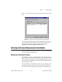
1
IVI Driver
Library
™
IVI Driver Library User Manual
IVI Driver Library User Manual
December 1998 Edition
Part Number 321629A-01
Internet Support
E-mail: [email protected]
FTP Site: ftp.natinst.com
Web Address: http://www.natinst.com
Bulletin Board Support
BBS United States: 512 794 5422
BBS United Kingdom: 01635 551422
BBS France: 01 48 65 15 59
Fax-on-Demand Support
512 418 1111
Telephone Support (USA)
Tel: 512 795 8248
Fax: 512 794 5678
International Offices
Australia 03 9879 5166, Austria 0662 45 79 90 0, Belgium 02 757 00 20, Brazil 011 288 3336,
Canada (Ontario) 905 785 0085, Canada (Québec) 514 694 8521, Denmark 45 76 26 00, Finland 09 725 725 11,
France 01 48 14 24 24, Germany 089 741 31 30, Hong Kong 2645 3186, Israel 03 6120092, Italy 02 413091,
Japan 03 5472 2970, Korea 02 596 7456, Mexico 5 520 2635, Netherlands 0348 433466, Norway 32 84 84 00,
Singapore 2265886, Spain 91 640 0085, Sweden 08 730 49 70, Switzerland 056 200 51 51, Taiwan 02 377 1200,
United Kingdom 01635 523545
National Instruments Corporate Headquarters
6504 Bridge Point Parkway Austin, Texas 78730-5039
USA Tel: 512 794 0100
© Copyright 1998 National Instruments Corporation. All rights reserved.
Important Information
Warranty
The media on which you receive National Instruments software are warranted not to fail to execute programming
instructions, due to defects in materials and workmanship, for a period of 90 days from date of shipment, as evidenced
by receipts or other documentation. National Instruments will, at its option, repair or replace software media that do not
execute programming instructions if National Instruments receives notice of such defects during the warranty period.
National Instruments does not warrant that the operation of the software shall be uninterrupted or error free.
A Return Material Authorization (RMA) number must be obtained from the factory and clearly marked on the outside
of the package before any equipment will be accepted for warranty work. National Instruments will pay the shipping costs
of returning to the owner parts which are covered by warranty.
National Instruments believes that the information in this manual is accurate. The document has been carefully reviewed
for technical accuracy. In the event that technical or typographical errors exist, National Instruments reserves the right to
make changes to subsequent editions of this document without prior notice to holders of this edition. The reader should
consult National Instruments if errors are suspected. In no event shall National Instruments be liable for any damages
arising out of or related to this document or the information contained in it.
EXCEPT AS SPECIFIED HEREIN, NATIONAL INSTRUMENTS MAKES NO WARRANTIES, EXPRESS OR IMPLIED, AND SPECIFICALLY DISCLAIMS
ANY WARRANTY OF MERCHANTABILITY OR FITNESS FOR A PARTICULAR PURPOSE. CUSTOMER’S RIGHT TO RECOVER DAMAGES CAUSED
BY FAULT OR NEGLIGENCE ON THE PART OF NATIONAL INSTRUMENTS SHALL BE LIMITED TO THE AMOUNT THERETOFORE PAID BY THE
CUSTOMER. NATIONAL INSTRUMENTS WILL NOT BE LIABLE FOR DAMAGES RESULTING FROM LOSS OF DATA, PROFITS, USE OF PRODUCTS,
OR INCIDENTAL OR CONSEQUENTIAL DAMAGES, EVEN IF ADVISED OF THE POSSIBILITY THEREOF. This limitation of the liability of
National Instruments will apply regardless of the form of action, whether in contract or tort, including negligence.
Any action against National Instruments must be brought within one year after the cause of action accrues. National
Instruments shall not be liable for any delay in performance due to causes beyond its reasonable control. The warranty
provided herein does not cover damages, defects, malfunctions, or service failures caused by owner’s failure to follow
the National Instruments installation, operation, or maintenance instructions; owner’s modification of the product;
owner’s abuse, misuse, or negligent acts; and power failure or surges, fire, flood, accident, actions of third parties,
or other events outside reasonable control.
Copyright
Under the copyright laws, this publication may not be reproduced or transmitted in any form, electronic or mechanical,
including photocopying, recording, storing in an information retrieval system, or translating, in whole or in part, without
the prior written consent of National Instruments Corporation.
Trademarks
CVI™, LabVIEW™, Measure™, natinst.com™, National Instruments™ , the National Instruments logo, PXI™, and
VirtualBench™ are trademarks of National Instruments Corporation.
Product and company names listed are trademarks or trade names of their respective companies.
WARNING REGARDING MEDICAL AND CLINICAL USE OF NATIONAL INSTRUMENTS PRODUCTS
National Instruments products are not designed with components and testing intended to ensure a level of reliability
suitable for use in treatment and diagnosis of humans. Applications of National Instruments products involving medical
or clinical treatment can create a potential for accidental injury caused by product failure, or by errors on the part of the
user or application designer. Any use or application of National Instruments products for or involving medical or clinical
treatment must be performed by properly trained and qualified medical personnel, and all traditional medical safeguards,
equipment, and procedures that are appropriate in the particular situation to prevent serious injury or death should always
continue to be used when National Instruments products are being used. National Instruments products are NOT intended
to be a substitute for any form of established process, procedure, or equipment used to monitor or safeguard human health
and safety in medical or clinical treatment.
Contents
About This Manual
Organization of This Manual .........................................................................................xi
Conventions Used in This Manual.................................................................................xii
IVI Driver Library Documentation Set..........................................................................xiii
Customer Communication .............................................................................................xiii
Chapter 1
Introduction to IVI
Installing IVI..................................................................................................................1-1
What the Setup Program Installs ...................................................................................1-1
IVI Class Drivers.............................................................................................1-1
Advanced Class Simulation Tools...................................................................1-2
IVI Instrument-Specific Drivers......................................................................1-2
IVI Engine .......................................................................................................1-2
VISA I/O Library ............................................................................................1-3
VirtualBench Soft Front Panels.......................................................................1-3
NI Spy..............................................................................................................1-3
IVI Configuration Utility.................................................................................1-3
Chapter 2
IVI Instrument Driver Overview
What Is an Instrument Driver?.......................................................................................2-1
Historical Evolution of Instrument Drivers ...................................................................2-1
The IVI Foundation .......................................................................................................2-2
IVI Instrument-Specific Drivers ....................................................................................2-3
Instrument Classes—Standard Instrument Programming Interfaces.............................2-4
A Word on Interchangeability .......................................................................................2-5
Using IVI Instrument Drivers ........................................................................................2-6
Chapter 3
IVI System Architecture
Overview........................................................................................................................3-1
Class Driver APIs ..........................................................................................................3-3
Class Driver Prefix ..........................................................................................3-3
Class Capability Groups ..................................................................................3-3
Inherent IVI Capabilities...................................................................3-4
Default Setup .................................................................................................................3-10
© National Instruments Corporation
v
IVI Driver Library User Manual
Contents
Instrument Simulation ................................................................................................... 3-11
Advanced Class Simulation........................................................................................... 3-13
Applying Values to Unused Extensions ........................................................................ 3-15
Interchangeability Checking.......................................................................................... 3-16
Interchangeability Checking Rules ................................................................. 3-16
Viewing Interchangeability Warnings ............................................................ 3-18
Spying............................................................................................................................ 3-19
Chapter 4
Configuring Your System
Launching the IVI Configuration Utility....................................................................... 4-1
IVI Configuration Utility Overview.............................................................................. 4-3
IVI Configuration Utility Organization .......................................................... 4-3
Editing IVI Configuration Items ..................................................................... 4-5
Changing the Items to which Another Item Refers .......................... 4-6
Logical Name Properties .................................................................. 4-8
Virtual Instrument Properties ........................................................... 4-9
Specific Driver Properties ................................................................ 4-17
Class Driver Properties ..................................................................... 4-19
Device Properties.............................................................................. 4-21
Simulation Virtual Instrument Properties......................................... 4-23
Simulation Driver Properties ............................................................ 4-23
Creating a Logical Name............................................................................................... 4-24
Step 1: Launch the Logical Name Wizard ...................................................... 4-24
Step 2: Select a Virtual Instrument ................................................................. 4-25
Step 3: Select a Driver .................................................................................... 4-28
Step 4: Select a Device.................................................................................... 4-30
Step 5: Summary ............................................................................................. 4-32
Swapping an Instrument ................................................................................................ 4-33
Advanced Topics ........................................................................................................... 4-33
Multiple IVI.INI Files ..................................................................................... 4-33
Run-Time Configuration................................................................................. 4-34
Chapter 5
Class Driver Operation
Using IVI Class Drivers ................................................................................................ 5-1
Using Class Drivers in LabWindows/CVI...................................................... 5-1
Using Class Drivers in LabVIEW................................................................... 5-4
Developing an Interchangeable Application ................................................................. 5-7
Using Logical Names and Virtual Channel Names ........................................ 5-7
Use High-Level Configuration Functions Rather Than Setting
Individual Attributes .................................................................................... 5-8
IVI Driver Library User Manual
vi
© National Instruments Corporation
Contents
Minimize the Use of Extension Capability Groups.........................................5-8
Completely Specify the State of the Instrument..............................................5-9
Use the Development Mode Settings for Inherent Attributes .........................5-10
Follow the Class Behavior Model ...................................................................5-12
Use the Default Setup to Configure Instrument-Specific Attributes...............5-13
Analyzing Your Program with NI Spy ..........................................................................5-13
Configuring NI Spy .........................................................................................5-13
Capturing Calls to IVI Class Drivers...............................................................5-14
Call Properties .................................................................................................5-16
Verifying Instrument Replacement Candidates .............................................................5-19
Developing a Reference Program....................................................................5-19
Testing the New Driver In Simulation Mode ..................................................5-20
Chapter 6
Advanced Class Driver Simulation
IVI Class Driver Overview ............................................................................................6-1
Configuring Simulation .................................................................................................6-2
Configuring the Simulation Virtual Instrument ..............................................6-4
Interactive Simulation....................................................................................................6-7
VXIplug&play Function Simulation ...............................................................6-9
Status Code Simulation ...................................................................................6-10
Measurement Data Simulation ........................................................................6-11
Non-Interactive Simulation............................................................................................6-13
Advanced Simulation Topics.........................................................................................6-13
Modifying the Simulation Driver ....................................................................6-13
User-Interface Requirements...........................................................................6-13
Enabling Simulation After Initializing ............................................................6-14
Appendix A
Customer Communication
Glossary
Index
© National Instruments Corporation
vii
IVI Driver Library User Manual
Contents
Figures
Figure 2-1.
IVI Driver Architecture......................................................................... 2-4
Figure 3-1.
Figure 3-2.
Figure 3-3.
Figure 3-4.
Figure 3-5.
Figure 3-6.
IVI System Architecture ....................................................................... 3-1
Relationship of the Class Driver and Specific Driver........................... 3-8
Class Simulation Driver ........................................................................ 3-13
IviDmm Simulation Driver User Interface ........................................... 3-14
Sample NI Spy Trace ............................................................................ 3-19
Sample NI Spy Property Page............................................................... 3-20
Figure 4-1.
Figure 4-2.
Figure 4-3.
Figure 4-4.
Figure 4-5.
Figure 4-6.
Figure 4-7.
Figure 4-8.
Figure 4-9.
Figure 4-10.
Figure 4-11.
Figure 4-12.
Figure 4-13.
Figure 4-14.
Figure 4-15.
Figure 4-16.
Figure 4-17.
Figure 4-18.
Figure 4-19.
The Explorer View of the IVI Configuration Utility ............................ 4-2
The Cabinet View of the IVI Configuration Utility.............................. 4-3
Change Virtual Instrument Dialog Box ................................................ 4-7
Logical Name Properties dialog box..................................................... 4-8
Virtual Instrument Tab.......................................................................... 4-10
Inherent Attribute Properties Tab ......................................................... 4-12
Virtual Channel Properties Tab ............................................................ 4-14
Default Attribute Setting Properties Tab .............................................. 4-15
Specific Driver Properties Dialog Box ................................................. 4-17
Class Driver Properties Dialog Box...................................................... 4-19
Device Properties Dialog Box .............................................................. 4-21
Logical Name Wizard ........................................................................... 4-24
Select a Virtual Instrument Panel ......................................................... 4-25
Virtual Instrument Information Panel ................................................... 4-27
Select a Driver Panel............................................................................. 4-28
Driver Information Pane ....................................................................... 4-29
Select a Device Panel............................................................................ 4-30
Device Information Panel ..................................................................... 4-31
Summary Panel ..................................................................................... 4-32
Figure 5-1.
Figure 5-2.
Figure 5-3.
Figure 5-4.
Figure 5-5.
Figure 5-6.
Figure 5-7.
Figure 5-8.
Figure 5-9.
Figure 5-10.
LabWindows/CVI Instrument Menu .................................................... 5-2
Set Attribute Function Panel Window .................................................. 5-4
IVI Class Drivers Palette ...................................................................... 5-5
LabVIEW IviDmm Class Driver Example ........................................... 5-6
LabVIEW Property Node ..................................................................... 5-6
Enabling Spying for IVI Class Drivers ................................................. 5-14
Calls to the IviScope Class Drive ......................................................... 5-15
Input Tab of the NI Spy Property Sheet Dialog Box ............................ 5-16
Output Tab of the NI Spy Property Sheet Dialog Box ......................... 5-17
Interchange Warnings Tab of the NI Spy Property Sheet
Dialog Box ............................................................................................ 5-18
Coercions Tab of the NI Spy Property Sheet Dialog Box .................... 5-19
Figure 5-11.
IVI Driver Library User Manual
viii
© National Instruments Corporation
Contents
Figure 6-1.
Figure 6-2.
Figure 6-3.
Figure 6-4.
Figure 6-5.
Properties Dialog Box ...........................................................................6-3
Default Setup Tab of IviScope Simulation Virtual Instrument
Properties Dialog Box ...........................................................................6-5
IviScope Simulation Setup Dialog Box.................................................6-8
Status Code Simulation View................................................................6-10
IviScope Measurement Data Simulation View .....................................6-12
Tables
Table 3-1.
Table 3-2.
Table 3-3.
Table 3-4.
IVI Class Prefixes..................................................................................3-3
Inherent IVI Functions ..........................................................................3-4
Inherent IVI Attributes .........................................................................3-5
Inherent IVI Functions Only Accessible Through the Class Driver .....3-9
Table 5-1.
Development Mode and Production Mode Settings for
Inherent Attributes.................................................................................5-10
Table 6-1.
IVI Class Simulation Drivers ................................................................6-1
© National Instruments Corporation
ix
IVI Driver Library User Manual
About This Manual
This manual and associated online function/VI references are intended for
both LabWindows/CVI and LabVIEW users. The IVI Driver Library User
Manual describes how to develop hardware independent test programs with
IVI (Interchangeable Virtual Instrument) instrument drivers. This manual
gives an overview of IVI instrument drivers and the IVI system
architecture. This manual also describes how to configure your system and
develop hardware independent test programs. Follow the guidelines in this
manual when you develop, debug, and deploy test programs that use IVI
instrument drivers.
Organization of This Manual
The IVI Driver Library User Manual is organized as follows:
•
Chapter 1, Introduction to IVI, explains how to install the IVI Driver
Library and what the setup program installs.
•
Chapter 2, IVI Instrument Driver Overview, introduces the concept of
instrument drivers and explains how they have evolved.
•
Chapter 3, IVI System Architecture, contains a general overview of the
components of the IVI system architecture, a description of the IVI
class drivers in detail, and a description of their relationship to specific
drivers.
•
Chapter 4, Configuring Your System, describes how you use the IVI
Configuration utility to create and configure logical names and virtual
instruments for your system. This chapter also describes how you use
the IVI Configuration utility to swap instruments without modifying,
recompiling, or re-linking your application program.
•
Chapter 5, Class Driver Operation, describes how you use the IVI
class drivers to develop interchangeable applications. This chapter also
discusses strategies you can use to maximize the interchangeability of
your application and to verify whether a new instrument can replace a
particular instrument in your application.
•
Chapter 6, Advanced Class Driver Simulation, describes how to
configure and use the advanced simulation features of the IVI class
drivers.
•
Appendix A, Customer Communication, contains forms you can use to
request help from National Instruments or to comment on our products
and manuals.
© National Instruments Corporation
xi
IVI Driver Library User Manual
About This Manual
•
The Glossary contains an alphabetical list and description of terms
used in this manual, including abbreviations, acronyms, metric
prefixes, mnemonics, and symbols.
•
The Index contains an alphabetical list of key terms and topics in this
manual, including the page where you can find each one.
Conventions Used in This Manual
The following conventions are used in this manual:
<>
Angle brackets enclose the name of a key on the keyboard—for example,
<shift>.
[]
Square brackets enclose optional items—for example, [response].
»
The » symbol leads you through nested menu items and dialog box options
to a final action. The sequence File»Page Setup»Options»Substitute
Fonts directs you to pull down the File menu, select the Page Setup item,
select Options, and finally select the Substitute Fonts options from the
last dialog box.
bold
Bold text denotes the names of menus, menu items, parameters, dialog
boxes, dialog box buttons or options, icons, windows, Windows 95 tabs,
or LEDs.
bold italic
Bold italic text denotes a note.
italic
Italic text denotes variables, emphasis, a cross reference, or an introduction
to a key concept.
monospace
Text in this font denotes text or characters that you should literally enter
from the keyboard, sections of code, programming examples, and syntax
examples. This font is also used for the proper names of disk drives, paths,
directories, programs, subprograms, subroutines, device names, functions,
operations, variables, filenames and extensions, and for statements and
comments taken from programs.
monospace bold
Bold text in this font denotes the messages and responses that the computer
automatically prints to the screen. This font also emphasizes lines of code
that are different from the other examples.
monospace italic
Italic text in this font denotes that you must enter the appropriate words or
values in the place of these items.
IVI Driver Library User Manual
xii
© National Instruments Corporation
About This Manual
paths
Paths in this manual are denoted using backslashes (\) to separate drive
names, directories, folders, and files.
IVI Driver Library Documentation Set
This manual describes in general how to use IVI class drivers and
IVI instrument-specific drivers to implement hardware independent
test systems. There are two online reference manuals, one for
LabWindows/CVI and one for LabVIEW. The online references describe
the specific details of each IVI class driver and how to use them with
LabWindows/CVI and LabVIEW.
Customer Communication
National Instruments wants to receive your comments on our products
and manuals. We are interested in the applications you develop with our
products, and we want to help if you have problems with them. To make it
easy for you to contact us, this manual contains comment and configuration
forms for you to complete. These forms are in Appendix A, Customer
Communication, at the end of this manual.
© National Instruments Corporation
xiii
IVI Driver Library User Manual
1
Introduction to IVI
This chapter explains how to install the IVI Driver Library and what the
setup program installs.
Installing IVI
To install the IVI Driver Library from CD, perform the following steps:
Note
National Instruments recommends that you close other applications before you
install the IVI Driver Library.
1.
If you plan to use the IVI Driver Library with LabVIEW or
LabWindows/CVI, make sure that you have already installed
LabVIEW or LabWindows/CVI.
2.
Insert your IVI Driver Library Installation CD into your CD-ROM
drive.
3.
Wait several seconds. With most PCs, the AutoRun utility on the
CD will automatically launch the IVI Driver Library Installation
CD dialog box.
4.
If the IVI Driver Library Installation CD dialog box does not appear,
select Run from the Start menu and type d:\setup in the input box,
where d is your CD-ROM drive. Click on OK.
What the Setup Program Installs
The setup program installs the following components on your hard disk.
IVI Class Drivers
The IVI Driver Library has five classes: oscilloscope, digital multimeter,
function/arbitrary waveform generator, power supply, and switch. You use
the IVI class drivers to develop hardware independent test programs. The
setup program installs the files necessary to use the class drivers with
LabWindows/CVI and LabVIEW.
© National Instruments Corporation
1-1
IVI Driver Library User Manual
Chapter 1
Introduction to IVI
For LabWindows/CVI, an IVI class driver consists of the following files:
•
The class driver program, which consists of a .dll file and import
library (.lib) files for various compilers.
•
The class driver include file (.h), which contains the function
declarations and constant definitions for the class.
•
The class driver function panel file (.fp), which contains information
that defines the function tree, the function panels, and the help text.
•
The .sub file, which documents attributes and their possible values.
•
A Windows help file (.hlp), which contains documentation for the
LabWindows/CVI class driver.
For LabVIEW, an IVI class driver consists of the following files:
•
The class driver VIs, which are in a .llb file.
•
The .rc file, which documents properties and their possible values.
•
A set of .mnu files, which document the hierarchy of VIs for the class
driver.
•
A Windows help file (.hlp), which contains documentation for the
LabVIEW class driver.
Advanced Class Simulation Tools
The advanced class simulation tools consist of a set of class simulation
drivers and user interface resource (.uir) files. The class simulation
drivers create simulation data for output parameters of class driver
functions. The class simulation drivers can run in two modes: interactive
and non-interactive. In the interactive mode, the class simulation drivers
display panels that are in the .uir files. With these panels, you configure
how the class simulation driver creates the output simulation data.
IVI Instrument-Specific Drivers
IVI instrument-specific drivers are software modules that contain functions
and attributes for controlling a specific GPIB, RS-232, VXI, or PXI
instrument.
IVI Engine
The IVI engine is a support library for the IVI class drivers and
instrument-specific drivers.
IVI Driver Library User Manual
1-2
© National Instruments Corporation
Chapter 1
Introduction to IVI
VISA I/O Library
The VISA (Virtual Instrument Software Architecture) Library gives
instrument drivers a single interface for controlling GPIB, VXI, PXI,
RS-232, or other types of instruments.
VirtualBench Soft Front Panels
VirtualBench soft front panels are applications that enable you to
interactively operate your instruments to ensure that they are operating
correctly and to make simple, interactive measurements. Each class driver
includes a soft front panel for controlling the instruments in your system.
The soft front panel is a very helpful troubleshooting tool when you are
debugging system issues or you want to take interactive measurements with
your equipment. Because the VirtualBench soft front panels are generic for
any instrument that plugs into the class drivers, you only have to learn how
to use it once for all instruments of a given class.
NI Spy
NI Spy is an application monitor for Windows applications that use
National Instruments drivers. It can monitor, record, and display calls made
to IVI class drivers. Use NI Spy to quickly locate and analyze any
erroneous calls your application makes to the IVI class drivers.
IVI Configuration Utility
Use the IVI Configuration utility to configure your instrument-independent
test system. With this utility, you create and configure IVI logical names.
In your program, you pass logical names to the class driver Prefix_init
function to identify the instruments and specific drivers to use.
© National Instruments Corporation
1-3
IVI Driver Library User Manual
IVI Instrument Driver Overview
2
This chapter introduces the concept of instrument drivers and explains how
they have evolved. This chapter then introduces the concept of IVI
instrument-specific and class drivers.
What Is an Instrument Driver?
In the early days of computer-controlled instrumentation systems,
programmers used BASIC I/O statements in their application programs to
send and receive command and data strings to and from the various
instruments connected to their computer through the GPIB. Each
instrument responded to particular ASCII strings as documented in each
vendor’s instrument user manuals. Programmers were responsible for
learning each command set and writing the control program.
Programming is often the most time-consuming part of developing an
automated test system, especially if programmers have to learn the various
command sets of the different instruments they use. This effect is
compounded when programmers find themselves repeating their work
when creating new applications with the same instruments. It became clear
that programmers could save much time and money if they wrote high-level
routines that hid the low-level commands. Also, if the routines were generic
and modular programmers could reuse them in any future application that
used the same instrument. These reusable routines became known as
instrument drivers.
Historical Evolution of Instrument Drivers
Although the concept of the instrument driver had promise, early
implementations had serious limitations. Some approaches were too
closely linked to proprietary development. Others were too difficult to
develop or modify. Users wanted drivers that were open and modifiable,
built around standards that allowed instruments from a variety of vendors
to peacefully coexist in one application.
© National Instruments Corporation
2-1
IVI Driver Library User Manual
Chapter 2
IVI Instrument Driver Overview
The VXIplug&play systems alliance actively worked to improve existing
instrument driver standards. The VXIplug&play instrument driver
architecture leveraged existing popular technology by building on the
successful LabWindows/CVI and LabVIEW instrument driver standards.
These standards enable system interoperability. That is, you can install
VXIplug&play instrument drivers from a variety of vendors on the same
system without encountering adverse system conflicts. In addition, these
standards use VISA-defined data types to define parameters of all
instrument driver functions. These data types promote the portability of
instrument drivers to new operating systems and programming languages.
However, the VXIplug&play model was not the last word in instrument
drivers.
The IVI Foundation
The IVI Foundation is an organization of end-users, instrument vendors,
and system integrators who share a common commitment to test system
developer success through open, powerful, instrument control technology.
The IVI Foundation has extended the VXIplug&play instrument driver
standards to incorporate features such as instrument interchangeability,
execution performance, and test development flexibility. The IVI model
takes the old model a step further without introducing additional
complexity or performance overhead. Although IVI instrument drivers
comply with the VXIplug&play standard, they have many additional
features. Some of the most important features are:
IVI Driver Library User Manual
•
Hardware Independence—The benefits of hardware independence
extend into a wide variety of application areas and industries. Test
system developers in the military and aerospace industries, who must
maintain test systems and code for many years, can easily reuse their
test code on new equipment as instruments improve or become
obsolete. Manufacturers in competitive, high-volume industries, such
as telecommunications and consumer electronics, can keep their
production lines running when instruments malfunction or must be
recalibrated. Large manufacturing companies of all kinds can more
easily reuse and share test code between departments and facilities
without being forced to use the same instrumentation hardware.
•
Instrument State Caching—Standard VXIplug&play drivers do not
keep track of the state of the instrument. Therefore, each measurement
function sets up the instrument for the measurement even if the
instrument is already configured correctly. IVI drivers automatically
cache the current state of the instrument. An IVI instrument driver
function performs instrument I/O only when the instrument settings
2-2
© National Instruments Corporation
Chapter 2
IVI Instrument Driver Overview
are different from what the function requires. This seemingly minor
difference in approach leads to significant reductions in test time and
cost.
•
Instrument Simulation—IVI drivers can simulate the operation of
instruments when they are not available. If you enable simulation, IVI
drivers do not perform instrument I/O. Instead, IVI drivers
range-check all input parameters and create simulated data for output
parameters. With simulated data, developers can develop code for
instruments even when the instruments are not available.
For a comprehensive list of IVI features, see Chapter 3, IVI System
Architecture.
IVI Instrument-Specific Drivers
Instrument drivers are high-level function libraries for controlling specific
GPIB, VXI, or serial instruments or other devices.
With an instrument driver, you can easily control an instrument without
knowing the low-level command syntax or I/O protocol. The IVI
instrument-specific drivers contain the information for controlling a
particular instrument model, including the command strings, parsing code,
and valid ranges of each setting for that particular instrument. IVI
instrument drivers apply an attribute-based approach to instrument control
to deliver better run-time performance and more flexible instrument driver
operation.
In the remainder of this manual the term specific driver is used to mean IVI
instrument-specific driver. A specific driver gives you the following
benefits over a traditional instrument driver.
•
State-caching—State-caching eliminates redundant commands being
sent to the instrument. If you try to set an attribute to a value that it
already has, the IVI engine skips the command.
•
Configurable range-checking—Range-checking verifies that a value
you specify for an attribute is within the valid range for the attribute.
You can disable this feature for faster execution speed.
•
Configurable status query—The status query feature automatically
checks the status register of the instrument after each operation. You
can disable this feature for faster execution speed.
•
Simple Simulation—You can develop application code that uses an
instrument driver even when the instrument is not available. When in
© National Instruments Corporation
2-3
IVI Driver Library User Manual
Chapter 2
IVI Instrument Driver Overview
simulation mode, the instrument driver range-checks input parameters
and generates simulated data for output parameters.
•
Multithread safety—You can use IVI instrument driver in
multithreaded applications. Multiple execution threads can use the
same IVI instrument session without interfering with each other.
Instrument Classes—Standard Instrument
Programming Interfaces
Interchangeability using IVI instrument-specific drivers is achieved
through generic instrument class drivers. A class driver is a set of functions
and attributes for controlling an instrument within a specified class, such as
an oscilloscope, DMM, or function generator. The IVI Driver Library has
five classes—oscilloscope, DMM, arbitrary waveform/function generator,
switch, and power supply. Each one of these class drivers makes calls to
IVI instrument-specific drivers to control the actual instruments.
From your test program, you make calls to the class drivers, which in turn
communicate through the specific drivers for your instruments. You can
change the specific instrument drivers (and corresponding instruments) in
your system underneath the class driver without affecting your test code.
Figure 2-1 shows how a class driver redirects function calls from a test
program to the correct specific instrument driver.
Test Program
IVI DMM
Class Driver
or
HP 34401
Specific Driver
Fluke 45
Specific Driver
Figure 2-1. IVI Driver Architecture
IVI Driver Library User Manual
2-4
© National Instruments Corporation
Chapter 2
IVI Instrument Driver Overview
The definition of the instrument classes was driven by the IVI Foundation.
The IVI Foundation’s charter is to define flexible programming interfaces
for instrument classes that meet the needs of test system developers. The
IVI Foundation has created specifications for common instrument classes.
The IVI Foundation specifications define each instrument class as a
collection of instrument attributes and a standard Application
Programming Interface (API) for programming these attributes. The
National Instruments IVI class drivers conform to the IVI Foundation
specifications.
For example, the oscilloscope class contains a collection of attributes that
are common to all oscilloscopes, such as vertical range, offset, timebase,
trigger mode, and so on. The class also contains functions for programmers
to set these attributes or retrieve data from the instrument, such as
ConfigureVertical, ConfigureHorizontal, ReadWaveform, and
so on. By defining a standard definition for each of these functions and
attributes for an oscilloscope, the IVI class specifications make it possible
for programmers to write test programs that work with any oscilloscope.
A Word on Interchangeability
Instrument interchangeability has long been a goal of many engineers
building test systems, particularly in the military and avionics industries.
It is important to realize that the instrument interchangeability that IVI
class drivers provide cannot exceed the fundamental interchangeability of
the underlying hardware in question. The requirements of your test system
are still the driving force behind your choice of particular instruments. For
example, your test system requires DMM measurements with 8-1/2 digits
of precision, you must use an 8-1/2 digit DMM. You cannot replace an
8-1/2 digit DMM with a 5-1/2 digit DMM in your test system, unless you
require only 5-1/2 digits of precision, regardless of the software
architecture. The IVI Driver Library implements a standard architecture for
swapping instruments that are capable of delivering the measurement
requirements of your test system.
© National Instruments Corporation
2-5
IVI Driver Library User Manual
Chapter 2
IVI Instrument Driver Overview
Using IVI Instrument Drivers
In general you operate and develop test programs with IVI instrument
drivers in the same way as with traditional instrument drivers. If you are
using LabWindows/CVI, refer to the LabWindows/CVI User Manual for
information on how to use instrument drivers with LabWindows/CVI.
If you are using LabVIEW, refer to the Instrument I/O VI topic in the
LabVIEW Online Reference for information on how to use instrument
drivers with LabVIEW.
A specific driver consists of the following files:
•
The instrument driver program, which consists of a source file (.c),
a .dll file, and an import library (.lib) file.
•
The instrument driver include (.h) file, which contains function
declarations and constant definitions.
•
The instrument driver function panel file (.fp), which contains
information that defines the function tree, the function panels, and the
help text.
•
The .sub file, which documents attributes and their possible values.
•
The .llb file which contains a set of LabVIEW VIs.
•
The .rc file, which documents properties and their possible values.
•
A set of .mnu files, which document the hierarchy of VIs.
The source code for a specific driver is the .c file. LabWindows/CVI is
optimized for the creation and modification of specific drivers. You use the
.fp and .sub files when you use an IVI instrument driver in the
LabWindows/CVI environment.
You use the .llb, .rc, and set of .mnu files when you use an IVI driver in
the LabVIEW environment. The VIs in the .llb file call the corresponding
functions in the instrument driver .dll file. Therefore, an IVI driver in
LabVIEW does not have G source code like a traditional LabVIEW driver.
LabVIEW instrument drivers previously shipped with G source code,
and LabVIEW programmers used the G source code to debug or optimize
the drivers. IVI drivers significantly reduce the necessity for instrument
driver source code, are of significantly higher quality than traditional
drivers and use state caching to optimize performance. The operation of IVI
drivers is highly configurable. You can optimize the operation of an IVI
driver without modifying the driver source code.
IVI Driver Library User Manual
2-6
© National Instruments Corporation
Chapter 2
IVI Instrument Driver Overview
A single source approach for IVI drivers has many advantages for
instrument driver users:
•
Driver developers can produce instrument drivers faster to cover more
instruments in your system.
•
The rigorous internal structure of IVI drivers results in higher quality
drivers than other existing models.
•
National Instruments can more easily maintain and upgrade instrument
drivers when each driver has only one set of source files. This results
in higher quality instrument drivers for you to choose from when
integrating a system.
•
Consistency between LabVIEW and LabWindows/CVI instrument
drivers means that it is easier for you to develop and maintain test
systems that use both LabVIEW and LabWindows/CVI.
© National Instruments Corporation
2-7
IVI Driver Library User Manual
3
IVI System Architecture
This chapter contains a general overview of the components of the IVI
system architecture, a description of the IVI class drivers in detail, and
a description of their relationship to specific drivers.
Overview
Figure 3-1 shows the components that make up an IVI system. In general,
to implement a test operation, you develop a program that controls
instruments. For each instrument model that you access, you use a specific
driver. The specific driver encapsulates all the information to control a
particular instrument model.
Test Program
IVI Configuration Utility
IVI Class Driver
IVI Specific Driver
IVI Engine
IVI Configuration File
Figure 3-1. IVI System Architecture
Your test program communicates with the specific driver in one of two
ways.
•
© National Instruments Corporation
Directly—Your test program can link directly to a specific driver. This
is similar to the way in which you use traditional instrument drivers.
3-1
IVI Driver Library User Manual
Chapter 3
IVI System Architecture
With this approach, you gain most of the benefits of IVI instrument
drivers, including state-caching, configurable range-checking,
configurable status query checking, simple simulation, and
multithread safety. All functions and attributes that the specific driver
exports begin with a prefix that uniquely identifies the specific driver.
Therefore, if you access a specific driver directly, you must modify
your test program code when you want to use a different instrument
model.
•
Through an IVI Class Driver—Your test program can access a
specific driver indirectly with an IVI class driver.
When you use an IVI class driver, you initialize the instrument by
calling the initialize function in the IVI class driver. You pass a logical
name to the initialize function. A logical name is a string that identifies
the specific driver and the physical instrument to use. You create and
configure logical names with the IVI Configuration utility.
To change the instrument that your program uses, you edit the logical
name to identify the new specific driver and physical instrument. You
do not have to change or recompile your program. Therefore, the class
driver allows you to develop hardware-independent test programs that
do not require modification when you use a different instrument. For a
complete description of the IVI Configuration utility refer to
Chapter 4, Configuring Your System.
As mentioned, you use IVI class drivers to develop hardware independent
test programs. A class driver is a set of functions and attributes for
controlling an instrument within a specified class, such as an oscilloscope,
DMM, or function generator. The IVI Driver Library has five classes:
oscilloscope, DMM, arbitrary waveform/function generator, switch, and
power supply.
In addition to interchangeability, IVI class drivers deliver other benefits
such as advanced simulation, spying, and interchangeability checking. This
section describes the features that are common to all IVI class drivers. For
information regarding a particular IVI class driver, refer to the IVI Driver
Library Online Reference.
The remainder of this chapter discusses the general features of IVI class
drivers in detail.
IVI Driver Library User Manual
3-2
© National Instruments Corporation
Chapter 3
IVI System Architecture
Class Driver APIs
The IVI class APIs conform to the specifications of the IVI Foundation.
Class Driver Prefix
The IVI class drivers work with a large set of specific drivers. Each class
driver has a unique Class Prefix that gives the class driver unique and
meaningful names and avoids conflicts with other instrument driver
functions, attributes, and files. The Class Prefix begins each function name
and attribute ID in the class driver and is the name of all component files
(.fp, .h, .dll, .llb, and so on) of the class driver. Table 3-1 show the
function, attribute ID, and filename prefixes for each IVI class driver.
Table 3-1. IVI Class Prefixes
IVI Class
Function Prefix
Attribute ID Prefix
Filename Prefix
Digital Multimeter
IviDmm
IVIDMM
ividmm.*
Oscilloscope
IviScope
IVISCOPE
iviscope.*
Function Generator
IviFgen
IVIFGEN
ivifgen.*
Power Supply
IviPower
IVIPOWER
ivipsup.*
Switch
IviSwtch
IVISWTCH
iviswtch.*
For example, the files that comprise the digital multimeter class driver are
ividmm.fp, ividmm.h, ividmm.dll, ividmm.lib, ividmm.sub,
ividmm.llb, ividmm.rc, and ividmm*.mnu. Each function name has
the prefix IviDmm, for example, IviDmm_Configure,
IviDmm_Initiate, and IviDmm_Fetch. Each attribute ID has the prefix
IVIDMM, for example, IVIDMM_ATTR_FUNCTION, IVIDMM_ATTR_RANGE,
and IVIDMM_ATTR_RESOLUTION.
Note
In LabVIEW, the VI names have spaces in place of the underscores.
Class Capability Groups
Because all instruments of a given class do not have identical functionality
or capability, it is impossible to create a single programming interface that
works with all of them. For this reason, the IVI class drivers divide the
instrument capabilities into Inherent IVI Capabilities, Fundamental
Capabilities, Extension Groups, and Instrument-Specific Capabilities.
© National Instruments Corporation
3-3
IVI Driver Library User Manual
Chapter 3
IVI System Architecture
Inherent IVI Capabilities
Inherent IVI Capabilities are the functions and attributes that all IVI class
drivers implement. Table 3-2 shows the inherent IVI functions. For a
complete description of the IVI inherent functions refer to the IVI Driver
Library Online Reference.
Table 3-2. Inherent IVI Functions
Category of Function
Initialize/Close Functions
ClassPrefix_init
ClassPrefix_close
Set/Get/Check Attribute
ClassPrefix_SetAttribute<type>
ClassPrefix_GetAttribute<type>
ClassPrefix_CheckAttribute<type>
Utility Functions
ClassPrefix_reset
ClassPrefix_self_test
ClassPrefix_revision_query
ClassPrefix_error_query
ClassPrefix_error_message
Error Info
ClassPrefix_GetErrorInfo
ClassPrefix_ClearErrorInfo
Interchangeability Info
ClassPrefix_GetNextInterchangeWarning
Coercion Info
ClassPrefix_GetNextCoercionRecord
Locking
ClassPrefix_LockSession
ClassPrefix_UnlockSession
IVI Driver Library User Manual
•
Initialize/Close Functions—Allow you to initialize and close
instrument driver sessions.
•
Set/Get/Check Attribute—Contains functions that set, get, and
check the values of attributes. There are type safe functions for each
attribute data type. The possible data types are ViInt32, ViReal64,
ViString, ViBoolean, and ViSession.
•
Utility Functions—Contains functions and sub-classes that control
common instrument operations. These functions include many of the
functions that VXIplug&play requires, such as reset, self-test, revision
query, error query, and error message. This class also contains
functions that access IVI error information, access interchangeability
warnings, access coercion records, and lock the instrument driver
session.
3-4
© National Instruments Corporation
Chapter 3
IVI System Architecture
Table 3-3 shows the inherent IVI attributes. For a complete description of
the inherent IVI attributes refer to the IVI Driver Library Online Reference.
Table 3-3. Inherent IVI Attributes
Category or Attribute
User Options
Range Check
Query Instrument Status
Cache
Simulate
Use Specific Simulation
Record Value Coercions
Interchangeability Check
Spy
Session Info
Specific Driver Prefix
Specific Driver Module
Pathname
Resource Descriptor
Logical Name
Class Driver Prefix
Instrument Capabilities
Number of Channels
Class Group Capabilities
Class Function Capabilities
Class Attribute Capabilities
Version Info
Driver Major Version
Driver Minor Version
Driver Revision
Class Major Version
Class Minor Version
Class Revision
Engine Major Version
Engine Minor Version
Engine Revision
Error Info
Primary Error
Secondary Error
Error Elaboration
© National Instruments Corporation
Defined Constant
CLASSPREFIX_ATTR_RANGE_CHECK
CLASSPREFIX_ATTR_QUERY_INSTR_STATUS
CLASSPREFIX_ATTR_CACHE
CLASSPREFIX_ATTR_SIMULATE
CLASSPREFIX_ATTR_USE_SPECIFIC_SIMULATION
CLASSPREFIX_ATTR_RECORD_COERCIONS
CLASSPREFIX_ATTR_INTERCHANGE_CHECK
CLASSPREFIX_ATTR_SPY
CLASSPREFIX_ATTR_SPECIFIC_PREFIX
CLASSPREFIX_ATTR_MODULE_PATHNAME
CLASSPREFIX_ATTR_RESOURCE_DESCRIPTOR
CLASSPREFIX_ATTR_LOGICAL_NAME
CLASSPREFIX_ATTR_CLASS_PREFIX
CLASSPREFIX_ATTR_NUM_CHANNELS
CLASSPREFIX_ATTR_GROUP_CAPABILITIES
CLASSPREFIX_ATTR_FUNCTION_CAPABILITIES
CLASSPREFIX_ATTR_ATTRIBUTE_CAPABILITIES
CLASSPREFIX_ATTR_DRIVER_MAJOR_VERSION
CLASSPREFIX_ATTR_DRIVER_MINOR_VERSION
CLASSPREFIX_ATTR_DRIVER_REVISION
CLASSPREFIX_ATTR_CLASS_MAJOR_VERSION
CLASSPREFIX_ATTR_CLASS_MINOR_VERSION
CLASSPREFIX_ATTR_CLASS_REVISION
CLASSPREFIX_ATTR_ENGINE_MAJOR_VERSION
CLASSPREFIX_ATTR_ENGINE_MINOR_VERSION
CLASSPREFIX_ATTR_ENGINE_REVISION
CLASSPREFIX_ATTR_PRIMARY_ERROR
CLASSPREFIX_ATTR_SECONDARY_ERROR
CLASSPREFIX_ATTR_ERROR_ELABORATION
3-5
IVI Driver Library User Manual
Chapter 3
IVI System Architecture
•
User Options—Contains attributes that the user can set to affect the
behavior of class drivers, specific drivers, and the IVI engine.
•
Session Info—Contains attributes that provide information about the
class driver and specific driver that created the session and the physical
resource it is using.
•
Instrument Capabilities—Contains attributes that describe various
capabilities of the instrument and the driver.
•
Version Info—Contains attributes that provide version information
about the class driver specific driver, and the IVI engine.
•
Error Info—Contains attributes for reporting and retrieving error
information.
Fundamental Capabilities
The fundamental capabilities are the functions and attributes of an
instrument class that are common to most of the instruments of that class.
The goal is to cover 95 percent of the instruments in a particular class. For
a specific driver to be compliant with a class, it must implement all the
fundamental capabilities.
For example, the fundamental capabilities of the oscilloscope class have
functions and attributes that configure an edge-triggered acquisition,
initiate an acquisition, and return the acquired waveform. For a complete
description of the fundamental capabilities for a particular class, refer to the
IVI Driver Library Online Reference.
Extension Groups
Extension groups are groups of functions and attributes that represent more
specialized features of an instrument class that are not common to all
instruments of that type. Specific instrument drivers are not required to
implement extension groups. With extension groups, the IVI class drivers
create standard programming interfaces for features and capabilities that
are not standard in every instrument of that class.
For example, although all oscilloscopes have very similar fundamental
capabilities for vertical and horizontal settings, there is a wide variety of
trigger modes among oscilloscopes. The IviScope class driver includes
extensions for different trigger modes, such as TV trigger, runt trigger,
width trigger, and so on. Every scope that has TV triggering can comply
with the TV trigger extension group functions and attributes of the IviScope
class. However, an oscilloscope that does not implement the TV trigger
extension group is still compliant with the IviScope class.
IVI Driver Library User Manual
3-6
© National Instruments Corporation
Chapter 3
IVI System Architecture
After you use an extension group in your program, any instrument you use
with the program must implement the extension group. The online help file
for the class drivers marks functions and attributes that are a part of an
extension group with a special symbol. For example, the online help for the
IviScope class driver marks the functions and attributes that control the TV
trigger extension group with the symbol [TV]. For a complete description
of the extension groups of a particular class refer to the IVI Driver Library
Online Reference.
Instrument-Specific Capabilities
In addition to the inherent IVI capabilities, fundamental instrument
capabilities, and extension groups, specific drivers can export whatever
instrument-specific functions and attributes the driver developer considers
necessary to control the non-interchangeable features of a device.
The instrument-specific capabilities are implemented in the specific driver
only. Therefore, if you want to use instrument-specific capabilities in your
test program, you must access the specific driver directly. Refer to the
online help of a specific driver for documentation regarding the
instrument-specific features of that instrument driver.
Your test program can access both the class driver and the specific driver
using the same instrument driver session. To do so, you must initialize the
instrument session by invoking the initialize function in the class driver.
You use the session that the class driver initialize function returns when you
invoke functions in the either the class driver or the specific driver. The
ability to call both class driver and specific driver functions with the same
IVI session allows you to develop test programs that are mostly
interchangeable and access instrument-specific capabilities only when
necessary. You must modify the portions of your test program that access
instrument-specific capabilities for your program to work with a different
instrument.
© National Instruments Corporation
3-7
IVI Driver Library User Manual
Chapter 3
IVI System Architecture
Class Driver Relationship to Instrument-Specific Drivers
Figure 3-2 illustrates an example of the relationship between the capability
groups of a class driver and a specific driver. In this example, the class
driver implements the inherent IVI capabilities, the fundamental
instrument capabilities, and two extension capability groups. The specific
driver implements the inherent IVI capabilities, the fundamental
instrument capabilities, one of the extension capability groups, and
instrument-specific capabilities.
The class driver dynamically loads the specific driver. The IVI class drivers
require that the specific driver be in a .dll, .c, .obj, or .lib file. The
specific drivers ship with .dll and .c files. If you are not using the class
drivers in LabWindows/CVI, you must use the .dll file. If you are using
LabWindows/CVI, it is usually best to use the .dll file.
Test Program
IVI Class Driver
Inherent IVI
Capabilities
Fundamental
Instrument
Capabilities
Extension
Capability
Group 1
Inherent IVI
Capabilities
Fundamental
Instrument
Capabilities
Extension
Capability
Group 1
Extension
Capability
Group 2
InstrumentSpecific
Capabilities
IVI SpecificDriver
Figure 3-2. Relationship of the Class Driver and Specific Driver
In general, when the Test Program calls functions and attributes of a
capability group in the class driver, the class driver maps these calls to the
corresponding capability group in the specific driver. If the test program
attempts to call extension group functions that the specific driver does not
implement, the class driver returns an error.
The class driver does not implement instrument-specific capabilities. The
test program accesses the instrument-specific capabilities by invoking
functions and attribute of the specific driver directly.
IVI Driver Library User Manual
3-8
© National Instruments Corporation
Chapter 3
IVI System Architecture
Your test program can access the inherent IVI capabilities, fundamental
instrument capabilities, and extension capabilities by invoking functions
and attributes in either the class or specific driver.
Note
To access the capabilities of the instrument through the class driver, you must
create the instrument driver session by calling the initialize function in the class
driver.
Figure 3-2 shows the relationship between the inherent IVI capabilities of
the class driver and specific driver with a dashed line because some inherent
IVI functions and attributes are accessible only through the class driver. If
you initialize an instrument driver session by calling the initialize function
in the specific driver, you cannot access the class-only functions and
attributes.
The ClassPrefix_GetNextInterchangeWarning function is
accessible only through the class driver.
The following table lists the inherent IVI attributes that are accessible only
through the class driver.
Table 3-4. Inherent IVI Functions Only Accessible Through the Class Driver
Use Specific Simulation
Record Value Coercions
Interchangeability Check
Spy
Specific Driver Prefix
Specific Driver Module Pathname
Resource Descriptor
Logical Name
Class Driver Prefix
Class Group Capabilities
Class Function Capabilities
Class Attribute Capabilities
Class Major Version
Class Minor Version
Class Revision
© National Instruments Corporation
CLASSPREFIX_ATTR_USE_SPECIFIC_SIMULATION
CLASSPREFIX_ATTR_RECORD_COERCIONS
CLASSPREFIX_ATTR_INTERCHANGE_CHECK
CLASSPREFIX_ATTR_SPY
CLASSPREFIX_ATTR_SPECIFIC_PREFIX
CLASSPREFIX_ATTR_MODULE_PATHNAME
CLASSPREFIX_ATTR_RESOURCE_DESCRIPTOR
CLASSPREFIX_ATTR_LOGICAL_NAME
CLASSPREFIX_ATTR_CLASS_PREFIX
CLASSPREFIX_ATTR_GROUP_CAPABILITIES
CLASSPREFIX_ATTR_FUNCTION_CAPABILITIES
CLASSPREFIX_ATTR_ATTRIBUTE_CAPABILITIES
CLASSPREFIX_ATTR_CLASS_MAJOR_VERSION
CLASSPREFIX_ATTR_CLASS_MINOR_VERSION
CLASSPREFIX_ATTR_CLASS_REVISION
3-9
IVI Driver Library User Manual
Chapter 3
IVI System Architecture
Default Setup
For some instruments, you might have to configure instrument-specific
attributes for the instrument to behave in an interchangeable manner.
However, configuring instrument-specific attributes in your program
significantly reduces the likelihood that your program can work with
another instrument.
When you initialize an instrument through a class driver, you can specify
default values for instrument-specific attributes. You specify the default
values for attributes with the IVI Configuration utility. The class driver
applies the default setup after it invokes the Prefix_IviInit function in
the specific driver. With the default setup mechanism you can configure
instrument-specific attributes external to your program.
This feature is also useful for extension group attributes. An example is the
IviDmm extension attribute that sets the power line frequency. Most DMMs
must know the power line frequency so that they can correctly calculate
aperture times based on power line cycles (PLCs). Typically, GPIB DMMs
have a built-in power supply and directly connect to the power line. Each
DMM can sense the power line frequency or else it has a thumbwheel
switch that you use to physically configure the power line frequency. For
these DMMs you cannot programmatically configure the power line
frequency, and the specific drivers for these instruments do not implement
the power line frequency attribute.
Alternatively, plug-in DMMs in a PXI, PCI, VXI, or PCMCIA form factor
do not directly connect to the power line. They receive power from the
computer or chassis in which they are installed. You must
programmatically configure the power line frequency for these DMMs to
operate. However, to configure the power line frequency attribute in your
program requires that any DMM that you use with the program implement
the power line frequency attribute. Thus, to maximize the number of
DMMs you can use, you configure the power line frequency attribute
through the default setup mechanism. If the next DMM you use with the
program does not implement the power line frequency attribute, you
remove the power line frequency from the default setup. Thus, your
program can work with DMMs that do or do not implement power line
frequency attribute.
For information on how to use the IVI Configuration utility to configure a
default setup, refer to Chapter 4, Configuring Your System.
IVI Driver Library User Manual
3-10
© National Instruments Corporation
Chapter 3
IVI System Architecture
Instrument Simulation
You can simulate your instrumentation hardware with IVI drivers. Using
the simulation features, you can develop test code even when your
instruments are not available. Simulation also is a key capability in testing
for interchangeability. If you build a test system on IVI technology, you can
integrate the driver of the new instrument and run test programs against this
driver in simulation mode. In effect, you can test a new instrument before
you purchase it to make sure it can work in your system.
An IVI driver implements three different simulation capabilities.
•
Instrument driver calls—The first requirement of instrument
simulation is simply being able to make function calls from your test
program to an instrument driver without each function returning an
error. When you enable simulation, IVI instrument drivers do not
attempt to communicate with the instrument. Therefore, you can make
instrument driver function calls from your program and not receive
I/O errors merely because the instrument is not present.
It is important to notice that you can use this simulation capability with
IVI class drivers as well as with specific drivers. This allows you to
simulate calls to a class driver and to instrument-specific functions in
the specific driver.
When you use a class driver, you can enable simulation with the IVI
Configuration utility. If you are using a specific driver directly, you
must use the Initialize With Options function in the specific driver. The
Initialize With Options function allows you to pass a string that presets
a number of driver attributes. One of these attributes is the simulation
attribute. Using this function to preset the simulation attribute alerts the
driver that the instrument is not connected to the computer.
•
Range Checking and Parameter Coercion—One of the key
responsibilities of the specific drivers is to range check and coerce all
input parameters. Every time you try to send a value to the instrument
to configure a particular setting, the driver first ensures that the value
is valid for the particular setting on the particular instrument model and
then coerces the value to an acceptable one for the instrument. The
range-checking and coercion operations happen completely in the
specific driver software.
Therefore, you do not have to connect the instrument to the computer
to perform range checking and coercion. This is the second level of
simulation that you can use with IVI drivers. When you write test code
without the instrument connected, the specific driver still ensures that
© National Instruments Corporation
3-11
IVI Driver Library User Manual
Chapter 3
IVI System Architecture
each value you are attempting to send to the instrument is valid, even
if it does not send the values to the instrument.
Note
The specific driver performs the range-checking and coercion operations.
Therefore, you can use this simulation capability with a class driver or a specific
driver.
•
Note
Simulated Output Data—For you to accurately simulate instruments
in a test program, the drivers must create simulated data for output
parameters of functions. The IVI architecture generates simulated data
in two different ways. Every specific driver has basic built-in simulated
data generation algorithms. For example, when you use a
DMM-specific driver in simulation mode, the Measure function
returns a random number within the valid range of the current mode of
the DMM. When you use an oscilloscope-specific driver in simulation
mode, the Read Waveform function returns an array of random
numbers within valid ranges for the scope. This simple data generation
process returns data values to the program variables so subsequent
function calls do not fail for lack of data. However, random data is not
very meaningful for your program or your units under test (UUTs).
The data generation capabilities just described are built into each specific driver
written with the instrument driver development wizard in LabWindows/CVI 5.0.
The driver wizard automatically inserts code into the measurement functions for
generating random data when the driver is in simulation mode.
Because you have access to the specific driver source code, you are
free to modify the driver. Therefore, you can add your own data
generation algorithms to generate simulated data that more closely
applies to the UUT or the application on which you are working.
However, this code is useful only for that particular specific driver. If
you change instruments in the future, you must re-implement this work
for each new instrument you add. For customized simulation code, the
IVI class drivers provide advanced simulation tools, which the
following section describes.
IVI Driver Library User Manual
3-12
© National Instruments Corporation
Chapter 3
IVI System Architecture
Advanced Class Simulation
The IVI class drivers provide advanced simulation tools for creating
simulated output data. The class drivers provide advanced simulation by
using a simulation driver. Simulation drivers are “virtual instruments” that
plug into a class driver. The class driver uses the simulation driver to
generate data.
For example, the IVI Driver Library includes five simulation drivers, one
for each class driver—oscilloscope, DMM, arbitrary waveform/function
generator, switch, and power supply. Each of these simulation drivers plugs
into the corresponding class driver to perform more flexible data generation
than the instrument-specific drivers. Figure 3-3 illustrates how a class
driver uses a class simulation driver.
Test Program
IVI Class Driver
1
Specific
Driver
2
Class Simulation
Driver
Figure 3-3. Class Simulation Driver
When your program makes a call to a class driver, the class driver calls the
corresponding function in the specific driver. When simulation is enabled,
the class driver opens an additional session to its class simulation driver.
Whenever you invoke a function in the class driver, the class driver first
calls the corresponding function in the specific driver and then calls the
same function in the class simulation driver. Under this mechanism, the
specific driver still range checks and coerces all input parameters, but the
class simulation driver is responsible for generating the simulated output
data.
Simulation drivers have two modes: interactive and non-interactive. You
specify whether to use interactive or non-interactive simulation with the
IVI Configuration utility. In interactive mode, simulation drivers have
pop-up user interface panels that allow you to configure the parameters for
generating the simulated output data.
© National Instruments Corporation
3-13
IVI Driver Library User Manual
Chapter 3
IVI System Architecture
For example, when you initialize the IviDmm class driver in simulation
mode, the simulation driver displays the panel shown in Figure 3-4.
Figure 3-4. IviDmm Simulation Driver User Interface
From the panel, you can select a base measurement value and an offset. For
example, in Figure 3-4, the panel settings specify a value of 10.0 with a
range of ±1.0. You can configure the driver to display the panel each time
the program calls a function that returns measurement data, or you can
configure it to generate the data automatically within the range you specify.
In automatic mode, the simulation driver returns data to the program
without requiring further user interaction.
In addition to generating simulated measurement data, you can use the
advanced class simulation features to generate simulated results for the
Self-Test, Error-Query, and Revision Query functions that all IVI drivers
export. You also can use the class simulation tools to generate simulated
completion codes for the instrument driver functions. This feature is useful
for verifying how your program handles error conditions that the
instrument driver might return.
IVI Driver Library User Manual
3-14
© National Instruments Corporation
Chapter 3
IVI System Architecture
All the features of the simulation driver are configurable through attributes
in the simulation driver. When you use non-interactive simulation, you
configure the attributes of the simulation driver with the IVI Configuration
utility. In this manner, you can configure how the simulation driver works
without modifying your test program code.
The IVI Driver Library includes C source code for the class simulation
drivers. You can develop very robust simulated data generation algorithms
for your test systems and plug them into the simulation drivers. Because
simulation drivers work with the class drivers, you can reuse the simulation
code you develop when you swap specific instruments.
Applying Values to Unused Extensions
In many cases, you might develop test programs that do not use one or more
of the extension groups that a class driver defines. Common sense says that
your program should work with instruments that do not implement the
extension group as well as with those that do. However, if your program
does not configure an extension group and the specific driver implements
the extension group, the values of the attributes in the unused extension
group are unknown. The attributes are likely to be set to the power-on
settings of the device. The power-on settings are likely to be different from
instrument to instrument and thus do not produce interchangeable behavior.
To accommodate instruments that implement extension groups that your
program never configures, the class driver sets the extension groups to an
interchangeable state. The interchangeable state for an extension group
configures the extension group to have no effect on the behavior of the
instrument.
For example, the IviDmm fundamental capabilities control DMMs that can
take a single measurement. The IviDmm class defines a multi-point
extension group that controls DMMs capable of acquiring multiple samples
from multiple triggers. If you develop a program that uses only the IviDmm
fundamental capabilities with an instrument that implements the
multi-point extension group, the IviDmm class driver sets the multi-point
extension group attributes to an interchangeable state when you call the
IviDmm_Initiate or IviDmm_Read functions.
To set the multi-point extension group to the interchangeable state, the
IviDmm class driver sets the trigger count attribute to 1 and the sample
count attribute to 1. In this configuration, the multi-point extension group
does not affect the instrument’s behavior. Therefore, you can run the
program with instruments that implement only the IviDmm fundamental
© National Instruments Corporation
3-15
IVI Driver Library User Manual
Chapter 3
IVI System Architecture
capabilities as well as with instruments that implement the multi-point
extension group.
If your program has ever set any of the values of an extension group,
the class driver does not configure the extension group. For information
regarding the interchangeable state that the class drivers apply for unused
extensions, refer to the IVI Driver Library Online Reference.
Interchangeability Checking
The IVI class drivers have a feature called interchangeability checking.
Interchangeability checking verifies that your program will produce the
same behavior when you use it with a different instrument.
You enable interchangeability checking with the IVI Configuration utility
or by setting the CLASSPREFIX_ATTR_INTERCHANGE_CHECK attribute to
VI_TRUE. Chapter 4, Configuring Your System, describes how to use the
IVI Configuration utility.
When you enable interchangeability checking, the class driver queues
warnings when it encounters instrument configurations that might not
produce the same behavior when you use a different instrument.
Interchangeability Checking Rules
The interchangeability check occurs when you call a class driver operation
that depends on the current state of the instrument. For example, the
IviDmm class driver performs interchangeability checking when your
program calls any of the following functions.
•
IviDmm_Initiate
•
IviDmm_Read
•
IviDmm_ReadMultiPoint
The class driver performs interchangeability checking on a capability group
basis. When interchangeability checking is enabled, the class driver always
performs interchangeability checking on the fundamental capabilities
group. In addition, the class driver performs interchangeability checking on
all extension groups for which you have set any of the attributes. If your
program has never set any attributes of an extension group, the class driver
does not perform interchangeability checking on that group.
IVI Driver Library User Manual
3-16
© National Instruments Corporation
Chapter 3
IVI System Architecture
In general, a class driver generates an interchangeability warning when it
encounters one of the following conditions:
•
An attribute that affects the behavior of the instrument is in a state that
you did not specify. This can happen if your program does not
configure the attribute or if your program configures the attribute but
the value becomes invalid as a result of your program configuring a
different attribute.
If an attribute is in a state that you did not specify, then the value of the
attribute is either a power-on setting of the instrument or a value that
the instrument sets based on the configuration of another attribute. In
either case, the value of the attribute, and therefore the behavior of the
instrument, is likely to be different when you run the program with a
different instrument.
•
You set a class attribute to an instrument-specific value. Many
attributes that a class driver defines represent a set of discrete settings.
For these attributes, the class driver defines the possible values to
which you can set the attribute. Specific drivers can define additional,
instrument-specific values for the attribute. When your program sets
an attribute to an instrument-specific value, it is likely to behave
differently when you run it with different instruments.
For example, the attribute that configures the measurement function in
the IviDmm class can have both class values and instrument-specific
values. The class driver defines values for common measurement
functions such as AC volts, DC volts, AC current, DC current, and
others. Specific drivers can define instrument-specific values for the
attribute. The constant values that one specific driver uses can overlap
with the constant values that other specific drivers use. One specific
driver might define an instrument-specific measurement function and
another specific driver might use the same value to define an entirely
different measurement function. Therefore, using an
instrument-specific value in your program can result in different
measurement results depending on which instrument you use.
•
You configure the value of an attribute that the class defines as read
only. In a few cases the class drivers define read only attributes that
specific drivers might implement as read/write.
The attributes of the IviDmm class that return the aperture time are
examples of this. With some DMMs, you can set the aperture time as
well as read it. The specific drivers for these DMMs might implement
the attributes for the aperture time as read/write. Most specific drivers
that are compliant with the class implement the attribute as read only.
© National Instruments Corporation
3-17
IVI Driver Library User Manual
Chapter 3
IVI System Architecture
Therefore, if your program configures an attribute that a class defines
as read-only, it is likely that your program will not work with other
instruments.
•
The class driver encounters an error when it tries to apply a value to an
extension attribute that your program never configures. The Applying
Values to Unused Extensions section earlier in this chapter describes
how the class driver sets the attributes of extension groups for which
you have never specified values. It sets the attributes to an
interchangeable state. The purpose is to make your program behave the
same regardless of whether the instruments you use implement the
extension group. Some instruments that implement the extension
group might not support the value to which the class driver attempts to
set the attribute. In this case, the class driver queues an
interchangeability warning instead of returning an error from the
function.
A good example is the attribute that configures the interpolation
method in the IviScope class. If your program never sets that value of
this attribute and the specific driver implements the attribute, the
IviScope class driver attempts to set the interpolation method to
Sin(x)/x. However, many oscilloscopes do not support this type of
interpolation. For these cases, the class driver generates an
interchangeability warning to indicate that the attribute that controls
the interpolation method is not in an interchangeable state.
Each IVI class driver defines exceptions to the interchangeability checking
rules and defines which functions perform interchangeability checking.
Refer to the IVI Driver Library Online Reference for the interchangeability
checking rules for a particular class.
Viewing Interchangeability Warnings
If the CLASSPREFIX_ATTR_SPY attribute is set to VI_TRUE, you can use
the NI Spy utility to view interchangeability warnings. The NI Spy utility
highlights functions in blue that have interchangeability warnings.
Chapter 5, Class Driver Operation, describes how to use the NI Spy utility
to view interchangeability warnings.
If the CLASSPREFIX_ATTR_SPY attribute is set to VI_FALSE, you can use
ClassPrefix_GetNextInterchangeWarning function to retrieve
interchangeability warnings programmatically. You can set the value of the
CLASSPREFIX_ATTR_SPY attribute with the IVI Configuration utility.
Chapter 4, Configuring Your System, describes how to use the IVI
Configuration utility.
IVI Driver Library User Manual
3-18
© National Instruments Corporation
Chapter 3
IVI System Architecture
Spying
NI Spy is an application monitor for Windows applications using
National Instruments drivers. It can monitor, record, and display calls made
to IVI class drivers. You can use NI Spy to quickly locate and analyze any
erroneous calls that your application makes to the IVI class drivers.
When you enable spying on a particular class driver session, NI Spy
captures all function calls that your application makes on that class driver
session. You enable spying on a particular class driver session with the
IVI Configuration utility or by setting the CLASSPREFIX_ATTR_SPY
attribute to VI_TRUE. Figure 3-5 shows a sample trace from the NI Spy
utility.
Figure 3-5. Sample NI Spy Trace
NI Spy records all input parameters you pass to a function and all output
parameters the function returns. NI Spy also displays the return value of the
function.
© National Instruments Corporation
3-19
IVI Driver Library User Manual
Chapter 3
IVI System Architecture
You can see detailed information for every call NI Spy captures through
property sheets. Figure 3-6 shows a sample property sheet.
Figure 3-6. Sample NI Spy Property Page
With the property sheets you can see detailed information such as the
following:
•
Information about the application that made each call and the time
stamp of the call.
•
The input and output parameters to each call, and the contents of buffer
parameters.
•
Descriptive error information.
•
Interchangeability warnings.
•
Information regarding the coercion of attribute values.
For complete information regarding the use of the NI Spy utility to monitor
calls to class drivers, refer to Chapter 5, Class Driver Operation.
IVI Driver Library User Manual
3-20
© National Instruments Corporation
Configuring Your System
4
This chapter describes how you use the IVI Configuration utility to create
and configure logical names and virtual instruments for your system. This
chapter also describes how you use the IVI Configuration utility to swap
instruments without modifying, recompiling, or re-linking your application
program.
When you call a class driver initialize function, you pass a logical name to
identify the particular virtual instrument to use. The virtual instrument, in
turn, identifies a particular physical instrument and specific driver and
specifies the initial settings for the session. If you want to use your program
with a different physical instrument, you change the configuration of the
logical name to use the virtual instrument for the new physical instrument.
You can change the initial settings for the session by changing the
configuration of the virtual instrument.
Launching the IVI Configuration Utility
The IVI Configuration utility is integrated into your Windows system and
appears in the Windows Explorer. To launch the IVI Configuration utility,
do one of the following.
•
Select Programs»National Instruments IVI Driver Library»IVI
Configuration from the Windows Start menu.
•
Double-click on the Measurement & Automation icon on the Windows
desktop.
© National Instruments Corporation
4-1
IVI Driver Library User Manual
Chapter 4
Configuring Your System
The explorer view of the IVI Configuration utility appears in Figure 4-1.
Figure 4-1. The Explorer View of the IVI Configuration Utility
The explorer view of the IVI Configuration utility contains a tree window
and a list window. The tree window displays a hierarchical list of the folders
that you can configure. The list window displays the contents of the folder
that you select in the tree window. To configure IVI logical names, open the
Measurement and Automation folder and then open the IVI folder.
IVI Driver Library User Manual
4-2
© National Instruments Corporation
Chapter 4
Configuring Your System
The cabinet view of the IVI Configuration utility appears in Figure 4-2.
Figure 4-2. The Cabinet View of the IVI Configuration Utility
The cabinet view of the IVI Configuration utility has only the list window.
To configure IVI logical names, open the IVI folder.
IVI Configuration Utility Overview
This section describes the organization of the IVI Configuration utility and
the various IVI configuration items that you can configure.
IVI Configuration Utility Organization
The IVI folder contains all the items you can configure for an IVI system.
The items are grouped into folders.
© National Instruments Corporation
4-3
IVI Driver Library User Manual
Chapter 4
Configuring Your System
The following table shows the hierarchy of folders in the IVI folder and the
icon that the IVI Configuration utility uses to identify the type of item each
folder contains.
Folder Name
Icon
none
IVI
Logical Names
Virtual Instruments
Simulation Virtual Instruments
Instrument Drivers
Class Drivers
Simulation Drivers
Devices
IVI Driver Library User Manual
•
IVI—The IVI folder contains a wizard that helps you create new
logical names. Refer to the Creating a Logical Name section in this
chapter for an example of how to use the Logical Name Wizard.
•
Logical Names—A logical name references a particular virtual
instrument in the Virtual Instruments folder. If you want to swap an
instrument, you edit the properties of the corresponding logical name
to reference a new virtual instrument.
4-4
© National Instruments Corporation
Chapter 4
Configuring Your System
•
Virtual Instruments—A virtual instrument refers a specific driver in
the Instrument Drivers folder and a particular device in the Devices
folder. The virtual instrument also specifies initial settings for
attributes.
•
Simulation Virtual Instruments—A simulation virtual instrument
refers to a particular simulation driver from the Simulation Drivers
folder and the initial attribute settings for the driver.
•
Instrument Drivers—An IVI specific driver configuration item
specifies a code module, such as a dynamic link library, for a specific
driver. The class driver uses the code module to communicate with the
device.
•
Class Drivers—An IVI Class driver configuration item refers to a
default simulation virtual instrument. The class driver uses the default
simulation virtual instrument when you enable simulation, unless the
virtual instrument for the session specifies another simulation virtual
instrument.
•
Simulation Drivers—An IVI simulation driver configuration item
specifies a code module, such as a dynamic link library, that a class
driver can use to simulate a device.
•
Devices—An IVI device configuration item specifies the address of a
device to use.
Editing IVI Configuration Items
In general, you use the IVI Configuration utility in the same way that you
use the Windows Explorer. You can select, cut, copy, paste, delete, and
rename items within each folder just as you do with files.
To create a new item, open the folder that contains the type of item you
want to create and do one of the following.
•
Right-click in the folder and select the Insert command from the
context menu.
•
Click on the Insert button in the toolbar.
You edit the properties of an item with the Properties dialog box for the
item. To display the Properties dialog box for an item, do one of the
following.
•
Double-click on the item.
•
Right-click on the item and select the Properties command from the
context menu.
© National Instruments Corporation
4-5
IVI Driver Library User Manual
Chapter 4
Configuring Your System
Changing the Items to which Another Item Refers
Many IVI configuration items refer to other items by name. For example,
each logical name refers to a virtual instrument, and each virtual instrument
refers to a device and a specific driver. The item that refers to another item
is called a parent item. The item to which a parent item refers is called a
child item. Notice that a parent item, such as a virtual instrument, can also
be a child item.
The IVI configuration items that refer to other items are logical names,
virtual instruments, class drivers, and simulation virtual instruments. The
Properties dialog boxes for these parent items display the names of the
child items to which they refer. A Change button and a Properties button
appear next to the name of each child item. You use the Change button to
specify a different child item. You use the Properties button to modify the
properties of the current child item.
To change the child item to which the parent item refers, click on the
Change button. A generic change item dialog box appears with a title that
is specific to the type of the child item.
IVI Driver Library User Manual
4-6
© National Instruments Corporation
Chapter 4
Configuring Your System
For example, if you click on the Change button of the Properties dialog box
for a logical name, the Change Virtual Instrument dialog box appears, as
shown in Figure 4-3.
Figure 4-3. Change Virtual Instrument Dialog Box
Each change item dialog box allows you to choose a new child item. You
can use an existing item, copy an existing item, or create a new item. To use
an existing item, select the Use an Existing item option, and choose an item
from the ring control below the option. Click on the OK button to return to
the original Properties dialog box.
To copy an existing item, select the Copy an Existing item option and select
an item to copy from the ring control below the option. To create a new
item, select the Create a New item option. If you copy an existing item or
create a new item, the IVI Configuration utility launches the corresponding
wizard when you click on the OK button. After the wizard executes, you
return to the original Properties dialog box.
© National Instruments Corporation
4-7
IVI Driver Library User Manual
Chapter 4
Configuring Your System
To view or modify the properties of the current child item, click on the
Properties button. The Properties dialog box for the current child item
appears. After you configure the properties, click on the OK button to
return to the original Properties dialog box.
The remainder of this section describes the information you configure with
the Properties dialog box for each IVI configuration item.
Logical Name Properties
You configure the properties of a logical name with the Properties dialog
box shown in Figure 4-4.
Figure 4-4. Logical Name Properties dialog box
IVI Driver Library User Manual
4-8
© National Instruments Corporation
Chapter 4
Configuring Your System
The Properties dialog box for a logical name displays the logical name, a
description, the instrument class, and the virtual instrument that the logical
name uses. The dialog box allows you to edit the description of the logical
name, edit the properties of the virtual instrument, and select a different
virtual instrument for the logical name to use.
You cannot modify the instrument class for the logical name. The class of
the virtual instrument to which the logical name refers determines the
instrument class for the logical name.
To view or modify the properties of the virtual instrument to which the
logical name currently refers, click on the Properties button. The
Properties dialog box for the virtual instrument appears. Refer to the
Virtual Instrument Properties section of this chapter for more information
regarding the Virtual Instrument Properties dialog box.
To configure the logical name to use a different virtual instrument, click on
the Change button. The Change Virtual Instrument dialog box appears.
Refer to the Changing the Items to which Another Item Refers section in
this chapter for more information regarding the Change Virtual Instrument
dialog box.
Virtual Instrument Properties
The Properties dialog box for a virtual instrument has tabs that allow you
to configure the various components of the virtual instrument.
© National Instruments Corporation
4-9
IVI Driver Library User Manual
Chapter 4
Configuring Your System
Virtual Instrument Tab
To configure the device and specific driver for the virtual instrument, click
on the Virtual Instrument tab shown in Figure 4-5.
Figure 4-5. Virtual Instrument Tab
The Virtual Instrument tab of the dialog box displays the virtual instrument
name, class, description, device, and specific driver. The dialog box allows
you to edit the description and to configure the device and specific driver.
You cannot modify the instrument class for the virtual instrument. The class
of the driver to which a virtual instrument refers determines the class of the
virtual instrument.
IVI Driver Library User Manual
4-10
© National Instruments Corporation
Chapter 4
Configuring Your System
To view or modify the properties of the device to which the virtual
instrument currently refers, click on the Properties button. The Properties
dialog box for the device appears. Refer to the Device Properties section in
this chapter for more information regarding the Device Properties dialog
box.
To configure the virtual instrument to use a different device, click on the
Change button. The Change Device dialog box appears. Refer to the
Changing the Items to which Another Item Refers section in this chapter for
more information regarding the Change Device dialog box.
To edit the properties of the driver that the virtual instrument is currently
using, click on the Properties button. The Properties dialog box for the
driver appears. Refer to the Specific Driver Properties section in this
chapter for more information regarding the Specific Driver Properties
dialog box.
To configure the virtual instrument to use a different driver, click on the
Change button. The Change Driver dialog box appears. Refer to the
Changing the Items to which Another Item Refers section in this chapter for
more information regarding the Change Driver dialog box.
Sometimes you must specify particular driver options at initialization time.
If you are using simulation, for example, you might want to specify a
particular instrument model from among a family of instruments the driver
supports. You can use the Driver Options control to specify a driver-specific
setup string. Refer to the documentation for the specific driver for more
information regarding the format of the driver-specific setup string.
Inherent Attributes Tab
To configure the inherent attributes of the virtual instrument, click on the
Inherent Attributes tab.
© National Instruments Corporation
4-11
IVI Driver Library User Manual
Chapter 4
Configuring Your System
The Inherent Attributes tab appears in Figure 4-6.
Figure 4-6. Inherent Attribute Properties Tab
You use the Operation controls group to configure most of the inherent IVI
attributes, such as state caching and range checking. When you call the
class driver initialize function, the class driver sets the inherent attributes to
the values you specify.
You use the Simulation controls group to configure how the class driver
simulates the specific instrument. To enable simulation, enable the
Simulate checkbox.
IVI Driver Library User Manual
4-12
© National Instruments Corporation
Chapter 4
Configuring Your System
The Output Data Simulation Source ring control specifies whether the class
driver or the specific driver generates the simulation data for output
parameters. If you select Class Driver from the Output Data Simulation
Source ring control, the class driver generates the simulation data for output
parameters. To do so, the class driver initializes a simulation driver that
generates the simulation data. The class driver determines which
simulation driver to initialize based on the contents of the Simulation
Virtual Instrument indicator.
To view or modify the properties of the simulation virtual instrument to
which the virtual instrument currently refers, click on the Properties
button. The Properties dialog box for the simulation virtual instrument
appears. Refer to the Simulation Virtual Instrument Properties section in
this chapter for more information regarding the Simulation Virtual
Instrument Properties dialog box.
To configure the virtual instrument to use a different simulation virtual
instrument, click on the Change button. The Change Simulation Virtual
Instrument dialog box appears. Refer to the Changing the Items to which
Another Item Refers section in this chapter for more information regarding
the Change Simulation Virtual Instrument dialog box.
If you select Specific Driver from the Output Data Simulation Source
ring control, the specific driver generates simulation data for output
parameters.
Channels Tab
If the class of the virtual instrument allows for multiple channels, you must
configure virtual channel names. You associate the particular channel
strings that the specific driver uses with the virtual channel names that your
application program uses. If you change the instrument to which the virtual
instrument refers and the driver for the new instrument uses different
channel strings than the old instrument, you must reconfigure the virtual
channel names.
© National Instruments Corporation
4-13
IVI Driver Library User Manual
Chapter 4
Configuring Your System
To configure the virtual channel names of the virtual instrument, click on
the Channels tab shown in Figure 4-7.
Figure 4-7. Virtual Channel Properties Tab
To create a new virtual channel name do the following.
IVI Driver Library User Manual
1.
Click on the New button.
2.
Enter the new virtual channel name in the Virtual Channel Name
control.
3.
Enter the instrument-specific channel string you want to associate with
the virtual channel name in the Specific Channel String control. Refer
to the documentation for the specific driver that you configure in the
Virtual Instrument tab for information regarding the specific channel
strings for the driver.
4-14
© National Instruments Corporation
Chapter 4
Configuring Your System
To modify an existing virtual channel name entry, select the particular entry
in the list box. The contents of the entry appear in the Virtual Channel
Name and Specific Channel String controls.
You can cut, copy, and paste entries in the list box by using the Cut, Copy,
and Paste buttons that are to the right of the list box.
Default Setup Tab
To configure the default setup of the virtual instrument, click on the Default
Setup tab shown in Figure 4-8.
Figure 4-8. Default Attribute Setting Properties Tab
The Default Setup tab allows you to configure attribute settings external to
your program. When you call the class driver initialize function, the class
© National Instruments Corporation
4-15
IVI Driver Library User Manual
Chapter 4
Configuring Your System
driver invokes the initialize function in the specific driver. After the
initialize function in the specific driver executes, the class driver applies the
default setup that you specify with this dialog box. The default setup feature
is very useful for setting the initial values of instrument-specific attributes.
To specify the default setting for a particular attribute do the following.
1.
Click on the New button.
2.
Enter the name of the attribute in the Attribute Name control. You do
not have to specify the prefix for the attribute. For example, you can
enter _ATTR_DB_MODE or DB_MODE instead of FL45_ATTR_DB_MODE.
Refer to the documentation for the specific driver for a complete list of
attributes that you can configure.
3.
Enter the initial value for the attribute in the Default Value control.
Refer to the documentation for the specific driver for a complete
description of the valid values for the attribute.
The default value you specify for an attribute must be the actual value. You
cannot use the name of a macro to specify a value. For ViBoolean
attributes, you enter True to enable the attribute, and False to disable the
attribute.
You specify default values for multi-channel attributes with a
semicolon-delimited list of channel:value pairs. To apply a value to all
channels that you do not configure explicitly, specify an asterisk (*) instead
of a channel name.
For example, if the specific driver supports four channels, ch1, ch2, ch3
and ch4, and you specify ch1:True;ch2:True;*:False as the default
value. For a multi-channel attribute, the attribute has the following value on
each channel: ch1 = True, ch2 = True, ch3 = False and ch4 = False.
In some cases, a specific driver might create additional channels after you
call the initialize function. If you specify a default value for a multi-channel
attribute with an asterisk as the channel, the class driver applies this value
to each new channel that the specific driver creates.
The class driver applies the default values in the order in which they appear
in the ring control list. It is best to place a dependent attribute lower in the
list than the attributes upon which it depends. For example, a FREQUENCY
attribute might have a maximum value of 1000 when the MODE attribute is
set to 1 and a maximum value of 2000 when the MODE attribute is set to 2.
If you want to set the initial value of the MODE attribute to 2 and the initial
value of the FREQUENCY attribute to 2000, the MODE attribute must appear
before the FREQUENCY attribute in the list box.
IVI Driver Library User Manual
4-16
© National Instruments Corporation
Chapter 4
Configuring Your System
Specific Driver Properties
You configure the properties of a specific driver with the Properties dialog
box shown in Figure 4-9.
Figure 4-9. Specific Driver Properties Dialog Box
The Properties dialog box for a specific driver allows you to configure the
description, module path, class, and function prefix.
The class is the name of the class driver with which the specific driver is
compliant. If, for example, the driver is compliant with the IviDmm class
driver, enter IviDmm in the Class control. If the driver is compliant with
more than one class, enter the name of each class separated by commas,
for example IviFgen, IviScope.
© National Instruments Corporation
4-17
IVI Driver Library User Manual
Chapter 4
Configuring Your System
The class that you specify determines the class of each virtual instrument
that refers to the particular specific driver. The class of each virtual
instrument, in turn, determines the class of the logical names that refer to
the virtual instrument. You can leave the Class control blank, but the class
information is helpful when you swap instruments.
When you call a class driver initialize function, the class driver loads the
specific driver module that you specify in the Module Path control. You
must enter the complete filename and path for the specific driver. You can
use the Browse button to select a particular specific driver file. The file
must be a .dll, .lib, or .obj file. If you are using a .dll file that is in
the system search path, you do not have to specify a path. Instead, you can
specify only the name of the .dll file. To use a .lib, or .obj file, you
must have the LabWindows/CVI run-time engine on your system.
If you are running your program in the LabWindows/CVI environment, you
can also use a .c file. If you use a .c file, you must include the file in the
LabWindows/CVI project. Using the .c file is useful for debugging.
After the class driver loads the specific driver, the class driver locates
functions in the specific driver module by name. The class driver creates
the function names on which to search by appending the names of
class-defined functions to the function prefix that you specify in the
Function Prefix control. The function prefix is case sensitive.
IVI Driver Library User Manual
4-18
© National Instruments Corporation
Chapter 4
Configuring Your System
Class Driver Properties
You configure the properties of a class driver with the Properties dialog box
shown in Figure 4-10.
Figure 4-10. Class Driver Properties Dialog Box
The Properties dialog box for a class driver allows you to configure the
description and the default simulation virtual instrument for the class
driver.
If you set the Simulation Virtual Instrument control on the Inherent
Attribute tab for the virtual instrument that you are simulating to Class
Driver Default, the class driver uses the default simulation virtual
instrument to generate simulated output data.
© National Instruments Corporation
4-19
IVI Driver Library User Manual
Chapter 4
Configuring Your System
To edit the properties of the simulation virtual instrument to which the class
driver currently refers, click on the Properties button. The Properties
dialog box for the simulation virtual instrument appears. Refer to the
Simulation Virtual Instrument Properties section in this chapter for more
information regarding the Simulation Virtual Instrument Properties dialog
box.
To configure the class driver to use a different simulation virtual
instrument, click on the Change button. The Change Simulation Virtual
Instrument dialog box appears. Refer to the Changing the Items to which
Another Item Refers section in this chapter for more information regarding
the Change Simulation Virtual Instrument dialog box.
IVI Driver Library User Manual
4-20
© National Instruments Corporation
Chapter 4
Configuring Your System
Device Properties
You configure the properties of a device with the Properties dialog box
shown in Figure 4-11.
Figure 4-11. Device Properties Dialog Box
The Properties dialog box allows you to configure the description and
resource descriptor for a particular device.
© National Instruments Corporation
4-21
IVI Driver Library User Manual
Chapter 4
Configuring Your System
The resource descriptor specifies the interface and address of the device.
Refer to the following table for the exact grammar to use. Optional fields
are shown in square brackets ([]).
Interface
Address Format
GPIB
GPIB[board]::<primary address>[::secondary address][::INSTR]
VXI
VXI[board]::<logical address>[::INSTR]
GPIB-VXI
GPIB-VXI[board]::<logical address>[::INSTR]
Serial
ASRL<port>[::INSTR]
DAQ
DAQ::<device number>[::INSTR]
Use the GPIB keyword for GPIB instruments. Use the VXI keyword for
VXI instruments that you control through embedded or MXIbus
controllers. Use the GPIB-VXI keyword for VXI instruments that you
control through a GPIB-VXI board. Use the ASRL keyword for serial
instruments. Use the DAQ keyword for NI-DAQ devices.
If you do not specify a value for an optional field, the following values are
used.
Optional String Segments
IVI Driver Library User Manual
Default Value
board
0
secondary address
none
INSTR
INSTR
4-22
© National Instruments Corporation
Chapter 4
Configuring Your System
The following table contains example valid resource names.
Resource Name
Description
GPIB::22::INSTR
GPIB board 0, primary address 22 no secondary address
GPIB::22::5::INSTR
GPIB board 0, primary address 22 secondary address 5
GPIB1::22::5::INSTR
GPIB board 1, primary address 22 secondary address 5
VXI::64::INSTR
VXI board 0, logical address 64
VXI1::64::INSTR
VXI board 1, logical address 64
GPIB-VXI::64::INSTR
GPIB-VXI board 0, logical address 64
GPIB-VXI1::64::INSTR
GPIB-VXI board 1, logical address 64
ASRL2::INSTR
COM port 2
DAQ::1::INSTR
DAQ device 1
Simulation Virtual Instrument Properties
You configure the properties of a simulation virtual instrument in the same
way that you configure the properties of a virtual instrument. The only
differences between the configuration of a virtual instrument and a
simulation virtual instrument are as follows.
•
Simulation virtual instruments reference simulation drivers instead of
specific drivers.
•
Simulation virtual instruments do not reference a device.
•
You cannot configure the IVI inherent attributes of a Simulation
Virtual Instrument.
•
You cannot configure the virtual channel names for a simulation virtual
instrument. The simulation virtual instrument uses the virtual channel
names for the virtual instrument it simulates.
Refer to the Virtual Instrument Properties section in this chapter for more
information regarding the configuration of virtual instruments.
Simulation Driver Properties
You configure the properties of a simulation driver in the same way that
you configure the properties of a specific driver. Refer to the Specific
Driver Properties section of this chapter for more information regarding
the configuration of drivers.
© National Instruments Corporation
4-23
IVI Driver Library User Manual
Chapter 4
Configuring Your System
Creating a Logical Name
You use the Add Logical Name wizard to create a new logical name.
Through a series of panels, the wizard prompts you for all the information
necessary to create a new logical name and create or configure all the IVI
configuration items that the logical name refers to.
Step 1: Launch the Logical Name Wizard
To invoke the wizard, launch the IVI Configuration utility, open the IVI
folder, and do one of the following.
•
Double-click the Add Logical Name icon.
•
Right-click in the Logical Names folder and select Insert from the
context menu.
The Logical Name Wizard panel is shown in Figure 4-12.
Figure 4-12. Logical Name Wizard
IVI Driver Library User Manual
4-24
© National Instruments Corporation
Chapter 4
Configuring Your System
Enter the name and description you want to use for the new logical name.
After the wizard executes, the new logical name appears in the Logical
Name folder with the name you enter in the Name control.
Click on the Next button to continue. At any time, you can click on the
Back button to return to a previous panel and change the information.
Step 2: Select a Virtual Instrument
The Select a Virtual Instrument panel is shown in Figure 4-13.
Figure 4-13. Select a Virtual Instrument Panel
The Select a Virtual Instrument panel prompts you to select the virtual
instrument you want to use for the new logical name. You can select an
existing virtual instrument or create a new virtual instrument.
© National Instruments Corporation
4-25
IVI Driver Library User Manual
Chapter 4
Configuring Your System
To use an existing virtual instrument, select the Use an Existing Virtual
Instrument option and choose a virtual instrument to use from the ring
control below the option. Then click on the Next button. If the existing
virtual instrument currently does not refer to a device, the wizard jumps to
Step 4. Otherwise, the wizard jumps to Step 5.
To create a new virtual instrument, select the Create a New Virtual
Instrument option.
IVI Driver Library User Manual
4-26
© National Instruments Corporation
Chapter 4
Configuring Your System
Click on the Next button to continue. The Virtual Instrument Information
panel appears in Figure 4-14.
Figure 4-14. Virtual Instrument Information Panel
Enter a name that uniquely identifies the new virtual instrument, and enter
a description. After the wizard executes, the new virtual instrument appears
in the Virtual Instruments folder with the name that you specify in the
Name control. The logical name that you create refers to the virtual
instrument by that name.
Click on the Next button.
© National Instruments Corporation
4-27
IVI Driver Library User Manual
Chapter 4
Configuring Your System
Step 3: Select a Specific Driver
The Select a Specific Driver panel is shown in Figure 4-15.
Figure 4-15. Select a Driver Panel
The Select a Specific Driver panel prompts you to select a specific driver.
The class driver uses the driver you select to communicate with the device.
The Select a Specific Driver panel operates similarly to the Select a Virtual
Instrument panel. You can select an existing driver or create a new driver.
To use an existing driver, select the Use an Existing Driver option and select
a driver to use from the ring control below the option. Then click on the
Next button. The wizard goes to Step 4.
To create a new driver, select the Create a New Driver option.
IVI Driver Library User Manual
4-28
© National Instruments Corporation
Chapter 4
Configuring Your System
Click on the Next button to continue.
The Specific Driver Information panel appears in Figure 4-16.
Figure 4-16. Specific Driver Information Pane
Enter the following information in the Specific Driver Information Panel.
•
A name that uniquely identifies the new driver.
•
A description for the driver.
•
The module path for the driver.
•
The class with which the driver is compliant.
•
The case-sensitive function prefix for the driver.
After the wizard executes, the new specific driver appears in the Instrument
Drivers folder with the name that you specify in the Name control. The
virtual instrument refers to the specific driver by that name.
Click on the Next button to continue.
© National Instruments Corporation
4-29
IVI Driver Library User Manual
Chapter 4
Configuring Your System
Step 4: Select a Device
The Select a Device panel appears in Figure 4-17.
Figure 4-17. Select a Device Panel
The Select a Device panel prompts you to select a device. The panel
operates similarly to the Select a Virtual Instrument panel. You can select
an existing device, create a new device, or select to simulate the device.
To use an existing device, select the Use an Existing Device option and
choose an existing virtual instrument from the ring control below the
To create a new device, select the Create a New Device option. To simulate
the device, select the None-Simulate the Device option.
Click on the Next button to continue.
IVI Driver Library User Manual
4-30
© National Instruments Corporation
Chapter 4
Configuring Your System
The Device Information panel appears in Figure 4-18.
Figure 4-18. Device Information Panel
Enter a name that uniquely identifies the new device, a description, and the
resource descriptor for the device. The resource descriptor is a string that
identifies the address of the device in the system. For a GPIB device, the
resource descriptor is a VISA resource descriptor such as
GPIB::2::INSTR. Refer to the Device Properties section in this chapter
for more information on the format of resource descriptors.
After the wizard completes, the new device appears in the Devices folder
with the name that you specify in the Name control. The new virtual
instrument refers to the device by that name.
Click on the Next button to continue.
© National Instruments Corporation
4-31
IVI Driver Library User Manual
Chapter 4
Configuring Your System
Step 5: Summary
The Summary panel appears in Figure 4-19.
Figure 4-19. Summary Panel
The Summary panel displays a summary of the new logical name. Click on
the Finish button to commit the changes and exit the wizard.
IVI Driver Library User Manual
4-32
© National Instruments Corporation
Chapter 4
Configuring Your System
Swapping an Instrument
To swap an instrument, open the Properties dialog box for the
corresponding logical name. In the dialog box, use the Change button to
create or select the virtual instrument for the new physical instrument.
Advanced Topics
This section describes more advanced configuration topics such as using
multiple configuration files and creating IVI configuration information at
run-time.
Multiple IVI.INI Files
The information that IVI Configuration utility and IVI class drivers access
resides in a file named ivi.ini. By default, the IVI configuration utility
and the IVI class drivers search for the ivi.ini file in the
<vxipnpbase>\niivi\ directory.
In some cases, you might want to have multiple ivi.ini files to define
different system configurations. To edit configuration information in an
ivi.ini file in a directory other than the <vxipnpbase>\niivi\
directory, do the following.
1.
Launch the IVI Configuration utility.
2.
Select the Measurement & Automation folder.
3.
Select the Open command from the File menu. The Open dialog box
appears.
4.
In the Open dialog box, select the IVI Configuration File entry.
Click on the Browse button to select the directory that contains the
ivi.ini file you want to edit. If you select a directory that does not
contain an ivi.ini file, the IVI Configuration utility prompts you to
create a new file.
To use a different ivi.ini file in your program, call the
Ivi_SetIviIniDir function to specify the pathname of the directory
where you want class drivers to search for the ivi.ini file. Call
Ivi_SetIviIniDir prior to calling any class driver initialize functions.
Refer to Chapter 11, IVI Library, of the LabWindows/CVI Instrument
Driver Developers Guide for information on the Ivi_SetIviIniDir
function.
© National Instruments Corporation
4-33
IVI Driver Library User Manual
Chapter 4
Configuring Your System
Run-Time Configuration
In some cases, you might not want to use a configuration file to specify
your IVI configuration. The IVI library contains functions you can use to
create run-time configuration information similar to the IVI Configuration
utility. The library also contains a function that writes the run-time
configuration information to a file. Following are the run-time
configuration functions.
•
Functions for creating and destroying logical names:
Ivi_DefineLogicalName
Ivi_UndefLogicalName
•
Functions for creating and destroying virtual instruments:
Ivi_DefineVInstr
Ivi_UndefVInstr
•
Functions for creating and destroying instrument drivers:
Ivi_DefineDriver
Ivi_UndefDriver
•
Functions for creating and destroying class drivers:
Ivi_DefineClass
Ivi_UndefClass
•
Functions for creating and destroying devices:
Ivi_DefineHardware
Ivi_UndefHardware
•
Function for saving the run-time configuration to a file:
Ivi_WriteRunTimeDefinesToFile
Refer to Chapter 11, IVI Library, of the LabWindows/CVI Instrument
Driver Developers Guide for more information regarding run-time
configuration functions.
IVI Driver Library User Manual
4-34
© National Instruments Corporation
Class Driver Operation
5
This chapter describes how you use the IVI class drivers to develop
interchangeable applications. This chapter also discusses strategies you can
use to maximize the interchangeability of your application and to verify
whether a new instrument can replace a particular instrument in your
application.
Using IVI Class Drivers
After you configure your system with the IVI Configuration utility, you
develop an interchangeable application by making calls to the IVI class
drivers. The class drivers isolate your program from the specific drivers
that communicate with the instruments.
Using Class Drivers in LabWindows/CVI
You use IVI class drivers in the LabWindows/CVI environment in the
same way that you use other LabWindows/CVI instrument drivers. You
can load and unload class drivers manually using the Instrument menu.
To load a class driver do the following:
1.
Select the Instrument»Load command.
2.
In the Load Instrument dialog box, select the function panel (.fp) file
for the class driver you want to load.
The class driver function panel files are in the cvi\instr\iviclass
directory.
© National Instruments Corporation
5-1
IVI Driver Library User Manual
Chapter 5
Class Driver Operation
Figure 5-1 shows the Instrument menu after you load the class drivers.
Figure 5-1. LabWindows/CVI Instrument Menu
You do not have to include the class drivers that you load through the
Instrument menu in your project, and you can load and unload them at any
time.
You can incorporate the IVI class drivers into your project by selecting
File»Add to Project in a Function Panel window or in the Edit»Add to
Project menu of the Project window. The .fp file represents the class
driver in the project list. If the .fp file is in the project list,
LabWindows/CVI automatically loads the class driver when you open the
project and removes the class driver when you unload the project.
A class driver function panel contains a function panel window for each
function that the class driver exports. With the function panel windows, you
can interactively call class driver functions and automatically generate code
for your application.
IVI Driver Library User Manual
5-2
© National Instruments Corporation
Chapter 5
Class Driver Operation
The class drivers have high-level and low-level functions. With the
high-level functions you can easily initialize and close the instrument,
configure the instrument, control instrument operations, and retrieve
measurements. For example, to set up and take a measurement using a
DMM, you might use the following statements in your program:
ViReal64 reading;
ViSession dmmHandle;
IviDmm_init ("DMM1", VI_TRUE, VI_TRUE, &dmmHandle);
IviDmm_Configure (dmmHandle, IVIDMM_VAL_DC_VOLTS,
IVIDMM_VAL_AUTO_RANGE_ON, IVIDMM_VAL_4_5_DIGITS,
20.0, 300000.0);
IviDmm_ConfigureTrigger (dmmHandle,
IVIDMM_VAL_IMMEDIATE, 0.0);
IviDmm_Read (dmmHandle, 5000, &reading);
IviDmm_close (dmmHandle);
The high-level configure functions allow you to set multiple instrument
attributes in a single operation. The class drivers also have low-level
functions you can use to access individual instrument driver attributes.
© National Instruments Corporation
5-3
IVI Driver Library User Manual
Chapter 5
Class Driver Operation
For example, Figure 5-2 shows the Set Attribute function panel for the
IviDmm class driver.
Figure 5-2. Set Attribute Function Panel Window
Refer to the LabWindows/CVI User Manual for complete information on
how to use function panels in LabWindows/CVI.
Using Class Drivers in LabVIEW
You use IVI class drivers in the LabVIEW environment in the same way
that you use other LabVIEW instrument drivers. The IVI class drivers are
in the IVI Class Drivers palette. To access the IVI Class Drivers palette,
select Functions»InstrumentI/O»IVI Class Drivers.
IVI Driver Library User Manual
5-4
© National Instruments Corporation
Chapter 5
Class Driver Operation
Figure 5-3 shows the IVI Class Drivers palette.
Figure 5-3. IVI Class Drivers Palette
There is a sub-palette for each IVI class driver. Each sub-palette contains
all the VIs for the corresponding class driver. The LabVIEW class drivers
have VIs that perform the same operations as the LabWindows/CVI class
drivers. To access a VI for a particular class driver, select the sub-palette
that corresponds to the class driver in the IVI Class Drivers palette.
© National Instruments Corporation
5-5
IVI Driver Library User Manual
Chapter 5
Class Driver Operation
Figure 5-4 shows a code example that uses the IviDmm class driver to
configure a DMM and take a measurement.
Figure 5-4. LabVIEW IviDmm Class Driver Example
In LabVIEW, you can access individual attributes with the property node.
Figure 5-5 shows how you can use the property node to access instrument
driver attributes. After LabVIEW calls IviDmmInit.vi, it uses the
Property Node to set values for the Function, Trigger Source and
Resolution.
Figure 5-5. LabVIEW Property Node
IVI Driver Library User Manual
5-6
© National Instruments Corporation
Chapter 5
Class Driver Operation
Refer to the VISA Library Reference section of the LabVIEW Instrument
I/O VI Reference Manual for complete information on how to use the
property node.
Developing an Interchangeable Application
This section describes issues to consider when you use IVI class drivers to
develop an instrument-independent test program. By following the
guidelines in this section, you can maximize the potential for your
application to work with other instruments.
Using Logical Names and Virtual Channel Names
You use logical names to identify a physical instrument and specific driver
without including instrument-specific information in your test program. In
general, it is best to create a logical name that fits the context of your
application irrespective of the instrument you are currently using.
When you create a logical name, you must consider whether you want to
use it across multiple applications. One approach is to create a logical name
that is global to all applications in your system. Another approach is to
create a unique logical name for each application.
If you create global logical names, you can quickly reconfigure your entire
system. When you replace an instrument, you have to reconfigure only one
logical name in the IVI Configuration utility. On the other hand, any change
to the configuration of the logical name in the IVI Configuration utility
affects all applications in your system. Thus, your freedom to replace an
instrument for any application is limited by the sum of the requirements of
all the applications that use the logical name. Also, this approach requires
that you coordinate the development of the applications you run on your
system so they all use the same set of logical names.
If you create a unique logical name for each application, you can customize
the configuration of the instrument for each application. On the other hand,
it may take you longer to reconfigure your system if you swap an
instrument that many applications use. Furthermore, this approach requires
that you coordinate the development of the applications you run on your
system so that they do not use the same logical names.
Virtual channel names allow you to identify a particular channel of an
instrument without using instrument-specific channel strings. Therefore,
you must give the same considerations to your selection of virtual channel
names as you do to your selection of logical names.
© National Instruments Corporation
5-7
IVI Driver Library User Manual
Chapter 5
Class Driver Operation
Use High-Level Configuration Functions Rather Than Setting
Individual Attributes
IVI class drivers have both high-level and low-level configuration
functions. The low-level configuration functions allow you to set values for
individual attributes. When you use the low-level functions to manipulate
attributes, you must understand the relationships and interactions between
the attributes for a particular instrument. You might have to set the attribute
values in a particular order for your program to work with a particular
instrument. When you replace the instrument, the attribute order
dependencies are likely to change. Therefore, you have to change the order
in which your program sets the attributes when you swap the instrument.
It is best to use the high-level functions to configure an instrument. The
high-level configuration functions group the setting of related attributes
into a single operation. When you call a high-level configuration function
in a class driver, the class driver invokes the corresponding function in the
specific driver. The specific driver is responsible for setting the attributes in
the correct order for the particular instrument. Also, the specific driver can
handle complex interactions between multiple attributes for the instrument.
If you swap instruments, the new specific driver sets the attributes in the
correct order and handles attribute interactions for the new instrument.
Minimize the Use of Extension Capability Groups
The class drivers divide the capabilities of an instrument class into
capability groups. The capability groups contain functions and attributes
that you use to access the features of that capability group. Each class driver
defines a fundamental capability group. A specific driver must implement
the fundamental capabilities group to be compliant with the class. Thus,
you always can use the fundamental capabilities group in your program.
The other capability groups are extension capability groups. Extension
capability groups represent the less common capabilities of the instrument
class. Specific drivers are not required to implement the extension
capability groups. Not all specific drivers implement the same set of
extension capability groups. Each time you use a new extension capability
group in your program, you limit the number of instruments that you can
use in your application.
It is best to use only the extension capability groups that your test program
requires. Minimizing the number of extension capability groups you access
for a particular IVI session maximizes the number of potential instruments
you can use with your application.
IVI Driver Library User Manual
5-8
© National Instruments Corporation
Chapter 5
Class Driver Operation
Completely Specify the State of the Instrument
To maximize interchangeability, you must completely specify the state of
the attributes that affect the behavior of the instrument. If you do not, the
behavior of your program depends on instrument-specific settings that can
result from any of the following conditions:
•
The power-on settings of the device.
•
The state that the instrument configures for an attribute as a result of
your program configuring other attributes.
•
The state that a previous program configured for the instrument.
If you fail to specify the state of the instrument completely, you increase
considerably the chance that your program will not behave the same way
when you swap instruments or you run your programs in a different order.
In general, after you access a particular capability group, you must
configure all attributes of that capability group that affect the behavior of
the instrument. Because all specific drivers that are compliant with a class
implement the fundamental capability group, you must completely specify
that state of the fundamental capabilities. After you access a particular
extension capability group, you must configure all attributes of that
extension group. Usually, you configure the attributes through one or more
high-level configuration functions.
It is important to note that not all attributes of a particular capability group
affect the behavior of the instrument. In some cases, if one attribute is set
to a particular value, a second attribute no longer affects the behavior of the
instrument. In such cases, you do not have to specify the state of the second
attribute.
For example, the IviDmm fundamental capabilities group defines the
IVIDMM_ATTR_AC_MIN_FREQ and IVIDMM_ATTR_AC_MAX_FREQ
attributes, which configure the minimum and maximum frequency
component of the input signal for AC measurements. These attributes
affect the behavior of the instrument only when you set the
IVIDMM_ATTR_FUNCTION attribute to an AC measurement. If you set the
IVIDMM_ATTR_FUNCTION attribute to a DC measurement such as DC
volts, you do not have to specify the states of the
IVIDMM_ATTR_AC_MIN_FREQ and IVIDMM_ATTR_AC_MAX_FREQ
attributes.
© National Instruments Corporation
5-9
IVI Driver Library User Manual
Chapter 5
Class Driver Operation
Use the Development Mode Settings for Inherent Attributes
IVI class drivers have many features that help you debug and analyze your
program. You enable these features by setting the development mode
settings for inherent attributes.
After you complete the development of your application and verify that
your program is working correctly, it is best to enable the production mode
settings for the inherent attributes. The production mode settings maximize
performance.
Refer to Chapter 4, Configuring Your System, for information about how to
use the IVI Configuration utility to set the development mode and
production mode settings for inherent attributes.
The following table lists the development mode and production mode
settings for the inherent attributes.
Table 5-1. Development Mode and Production Mode Settings for Inherent Attributes
Development
Mode Setting
Production
Mode Setting
CLASSPREFIX_ATTR_SPY
VI_TRUE
VI_FALSE
CLASSPREFIX_ATTR_RANGE_CHECK
VI_TRUE
VI_FALSE
CLASSPREFIX_ATTR_QUERY_INSTR_STATUS
VI_TRUE
VI_FALSE
CLASSPREFIX_ATTR_INTERCHANGE_CHECK
VI_TRUE
VI_FALSE
CLASSPREFIX_ATTR_RECORD_COERCIONS
VI_TRUE
VI_FALSE
Inherent Attribute
•
CLASSPREFIX_ATTR_SPY —Enables/disables spying. If you enable
spying, the class driver logs all calls you make to class driver functions.
You can view information about each call in the NI Spy utility. The
Analyzing Your Program with NI Spy section in this chapter describes
how to use the NI Spy utility to capture and view calls that your
program makes to the class drivers.
•
CLASSPREFIX_ATTR_RANGE_CHECK —Enables/disables range
checking. If you enable range checking, the specific driver checks all
parameters that you pass to the class driver and specific driver
functions.
•
CLASSPREFIX_ATTR_QUERY_INSTR_STATUS —Enables/disables
instrument status checking. If you enable instrument status checking,
the specific driver checks the status of the instrument after each call
your program makes to the class driver or specific driver.
IVI Driver Library User Manual
5-10
© National Instruments Corporation
Chapter 5
•
Class Driver Operation
CLASSPREFIX_ATTR_INTERCHANGE_CHECK —Enables/disables
interchangeability checking. Interchangeability checking verifies that
your program will produce the same behavior when you use it with a
different instrument. If you enable interchangeability checking, the
class driver queues warnings when it encounters instrument
configurations that are not likely to produce the same behavior when
you use a different instrument. Refer to Chapter 3, IVI System
Architecture, for a complete description of interchangeability
checking.
If you enable spying, you can use the NI Spy utility to view
interchangeability warnings. The NI Spy utility highlights class driver
functions that report interchangeability warnings in blue. If you
disable spying, you can use the
CLASSPREFIX_GetNextInterchangeWarning function to retrieve
interchangeability warnings programmatically.
•
CLASSPREFIX_ATTR_RECORD_COERCIONS —Enables/disables
coercion recording. In many cases, specific drivers coerce the value
you specify for a function parameter or attribute to a value the
instrument can accept. Specific drivers may coerce a value only if the
new value results in instrument behavior that is the same or better than
what you requested. Coercion of values is essential for instrument
interchangeability. If specific drivers did not coerce values, you would
have to specify values that were valid for the specific instruments
you use. If you attempted to use your program with new instruments,
the valid values would likely be different.
For example, the IviDmm class defines an attribute called
IVIDMM_ATTR_RANGE, that you use to specify the measurement
range. Typically, DMMs have a discrete set of ranges. One DMM
might have discrete settings for the range attribute such as 1 volt,
10 volts, and 100 volts. Another DMM might have discrete settings
such as 2 volts, 20 volts, and 200 volts. If you use the first instrument,
you might set the range attribute to 10.0. If you then attempt to run
your program with the second instrument, 10.0 is no longer an
acceptable value. The specific driver for the second instrument
therefore coerces the value to 20.0.
In other cases, specific drivers coerce the value you specify for an
attribute to the value the instrument would coerce the value to. This is
necessary to implement the state-caching feature of IVI. For example,
if a DMM has discrete settings for the range attribute of 1 volt, 10 volts,
and 100 volts, it coerces any value between 2 and 9 volts to 10 volts.
Thus, if you set the range to 2 volts, then to 7 volts, and then to 5 volts,
the actual range remains at 10 volts. To prevent sending redundant
© National Instruments Corporation
5-11
IVI Driver Library User Manual
Chapter 5
Class Driver Operation
commands to the instrument, the specific driver coerces the value
internally, sends the coerced value to the instrument, and caches the
coerced value. In the example, the specific driver coerces 2 volts to
10 volts, sends 10 volts to the instrument, and caches 10 volts. When
you set the range to 5 and 7 volts, it coerces these values to 10 volts,
notices that 10 volts is the current cache value, and thus does not send
any commands to the instrument.
If you enable coercion recording, the class driver keeps a record of
each case in which that the specific driver coerces ViInt32 or
ViReal64 values. You can view the coercion records to understand
how the specific driver coerces values that you specify in your
program.
If you enable spying, you can use the NI Spy utility to view the
coercion information. If you disable spying, you can use the
CLASSPREFIX_GetNextCoercionRecord function to retrieve the
coercion information programmatically.
Follow the Class Behavior Model
Each IVI class driver defines a behavior model. The behavior model
describes the relationships between the functions and attributes of the
driver and the behavior of the instrument. The behavior model also
describes the order of operations for configuring an instrument and
controlling instrument operations.
For example, the IviFgen behavior model recommends that you configure
the function generator only when the function generator is in the Idle state.
After you configure the function generator, you use the initiate operation to
begin generating the waveform. If you want to reconfigure the instrument,
you must first use the abort operation to return the instrument to the Idle
state. Although some function generators allow you to configure the
waveform while the instrument is generating the waveform, doing so might
limit the number of instruments you can use with your program.
By following the behavior model for each class, you maximize the
possibility of using your program with other instruments. The
LabWindows/CVI function panel help and the LabVIEW panel help for
each class driver describes the behavior model. The IVI Driver Library
Online Reference also describes the behavior model for each class.
IVI Driver Library User Manual
5-12
© National Instruments Corporation
Chapter 5
Class Driver Operation
Use the Default Setup to Configure Instrument-Specific Attributes
For some instruments, you might have to configure instrument-specific
attributes for the instrument to behave interchangeably. However,
configuring instrument-specific attributes in your program significantly
reduces the likelihood that your program can work with another instrument.
When you initialize an instrument through a class driver, you can use the
IVI Configuration utility to specify default values for instrument-specific
attributes. The class driver applies the default setup after it invokes the
Prefix_IviInit function in the specific driver. By using the default
setup mechanism, you can configure instrument-specific attributes outside
of your program.
For information on how to use the IVI Configuration utility to configure a
default setup, refer to Chapter 4, Configuring Your System.
Analyzing Your Program with NI Spy
NI Spy is an application monitor for Windows applications. It can monitor,
record, and display calls made to IVI class drivers and other National
Instruments APIs. This section describes how to use the NI Spy utility to
monitor calls that your program makes to IVI class drivers.
Configuring NI Spy
To spy on a particular logical name, you must enable spying for that logical
name and the IVI class driver. Refer to Chapter 4, Configuring Your
System, for a description of how to use the IVI Configuration utility to
enable spying for a particular logical name.
You enable spying for an IVI class driver in the NI Spy utility. To launch
the NI Spy utility, select Programs»VXIpnp»NI Spy from the Windows
Start menu. To enable spying for a particular class driver, select the name
of the class driver in the Spy menu. The class drivers appear below the
Restore Software on Exit command with the other APIs you can spy on.
© National Instruments Corporation
5-13
IVI Driver Library User Manual
Chapter 5
Class Driver Operation
By default, spying for all class drivers is enabled. Figure 5-6 shows the
Spy menu.
Figure 5-6. Enabling Spying for IVI Class Drivers
Capturing Calls to IVI Class Drivers
To view calls to IVI class drivers, you must enable capturing. When you
open NI Spy, capturing is off. To enable capturing, do one of the following:
•
Select Spy»Start Capture
•
Click the blue arrow button on the toolbar
•
Press <F8>
After you enable capturing, run your application and then return to NI Spy
to view the captured calls. For a complete description of how to use the
NI Spy utility, refer to the NI Spy Windows help. To view the Windows help
IVI Driver Library User Manual
5-14
© National Instruments Corporation
Chapter 5
Class Driver Operation
for NI Spy, select Help»Help Topics. Figure 5-7 shows calls to the
IviScope class driver that NI Spy captured.
Figure 5-7. Calls to the IviScope Class Drive
The NI Spy utility displays the name of each class driver function call it
captures. For each function call, the NI Spy utility displays the values of the
input and output parameters. NI Spy also displays the return value of the
function, the time when it captured the call, and the ID of the process that
made the call.
If a function returns an error, NI Spy highlights the function call in red. If
you enable interchangeability checking, NI-Spy highlights the functions
that report interchangeability warnings in blue.
© National Instruments Corporation
5-15
IVI Driver Library User Manual
Chapter 5
Class Driver Operation
Call Properties
NI Spy records detailed information about each call that it captures. To see
the detailed information for a specific call, do one of the following:
•
Double-click on the call in the capture window
•
Click on the call and press <Enter>.
•
Click on the call and select View»Properties.
•
Click on the call and then click on the Properties button on the toolbar.
For a complete description of the information that you can view in the
NI Spy Property Sheet dialog box, refer to the Windows help for NI Spy.
The Property Sheet dialog box contains additional information when it
shows a call to an IVI class driver. The remainder of this section describes
additional information you can view for calls to IVI class drivers.
Figure 5-8 shows the Input tab of the Property Sheet dialog box.
Figure 5-8. Input Tab of the NI Spy Property Sheet Dialog Box
The Input tab of the NI Spy Property Sheet dialog box displays the input
parameters value for a function call. When you call the class driver
initialize function, you pass the logical name of the instrument you want to
initialize. The initialize function returns an IVI session handle that
identifies the instrument session. You pass the IVI session handle as the vi
input parameter to all other class driver functions. For functions that have a
vi input parameter that represents an IVI session handle, NI Spy displays
IVI Driver Library User Manual
5-16
© National Instruments Corporation
Chapter 5
Class Driver Operation
the value of the vi parameter and the logical name that corresponds to the
value. Thus, you can easily identify the particular instrument session that a
call accesses.
The Output page displays the output parameters and status information for
the function call. For calls to an IVI class driver, NI Spy displays additional
error information. This information includes the primary error, the
secondary error, and any error elaboration information.
Figure 5-9 shows the Output tab of the NI Spy Property Sheet for a call to
an IVI class driver.
Figure 5-9. Output Tab of the NI Spy Property Sheet Dialog Box
You can view interchangeability warnings with NI Spy. If you enable
interchangeability checking and a class driver function encounters an
interchangeability warning, an Interchange Warnings tab appears on the
NI Spy Property Sheet dialog box for the function call. The Interchange
Warnings tab displays the interchangeability warnings that the function call
produced.
© National Instruments Corporation
5-17
IVI Driver Library User Manual
Chapter 5
Class Driver Operation
Figure 5-10 shows the Interchange Warnings tab of the NI Spy Property
Sheet dialog box.
Figure 5-10. Interchange Warnings Tab of the NI Spy Property Sheet Dialog Box
You can view how the specific driver coerces ViInt32 and ViReal64
values with NI Spy. If you enable coercion recording and the specific driver
coerces values that you pass to a class driver function, a Coercions tab
appears on the NI Spy Property Sheet dialog box for the function call.
IVI Driver Library User Manual
5-18
© National Instruments Corporation
Chapter 5
Class Driver Operation
Figure 5-11 shows the Coercions tab of the NI Spy Property Sheet dialog
box.
Figure 5-11. Coercions Tab of the NI Spy Property Sheet Dialog Box
The Coercions tab displays the name of the attribute that the specific driver
coerced, the value that you specified in your program, and the value to
which the specific driver coerced the attribute. If the attribute is
channel-based, the tab also displays the channel name.
Verifying Instrument Replacement Candidates
This section describes techniques you can use to verify if a new instrument
can work with an existing application.
Developing a Reference Program
One technique is to create a reference program. You create the reference
program when you specify the requirements of your test program or when
you develop your test program. The reference program uses an IVI class
driver to describe programmatically all the instrument configurations and
operations that you require.
To verify whether a new instrument can work with your program, execute
the reference program using the specific driver for the new instrument.
You can run the reference program with the physical instrument or with
© National Instruments Corporation
5-19
IVI Driver Library User Manual
Chapter 5
Class Driver Operation
simulation enabled. If you can execute the reference program without
errors using the new instrument, then it is likely that you can use the new
instrument with your existing application. Depending on how many errors
and the types of errors the reference program generates, you can gauge the
degree to which you must modify your program to make it work with the
new instrument.
Testing the New Driver In Simulation Mode
If you do not have a reference program, you can try to run your program
with the new instrument. If it is not possible to connect to the physical
instrument, you can enable simulation.
Often the analysis routines in your test program depend on the data that an
instrument returns. If the instrument does not return valid data, the program
returns an error and does not fully execute all the statements that control the
instrument. If you enable simulation, you can use the class simulation
drivers to create simulated date so that you can fully execute your test
program.
If you can execute your program using the new instrument, then it is likely
that you can replace your existing instrument with the new one.
IVI Driver Library User Manual
5-20
© National Instruments Corporation
6
Advanced Class Driver
Simulation
This chapter describes how to configure and use the advanced simulation
features of the IVI class drivers.
IVI Class Driver Overview
The IVI class drivers implement advanced simulation features by using
simulation drivers. The IVI Driver Library installs a simulation driver for
each IVI class driver. Each simulation driver “plugs in” to the
corresponding class driver and performs flexible output data simulation.
Table 6-1 lists the simulation driver files that the IVI Driver Library installs.
Table 6-1. IVI Class Simulation Drivers
Class Simulation Drivers
© National Instruments Corporation
Driver Files
IviScope
nisscope.dll, nisscope.c,
nisscope.h, nisscopu.uir,
nisscopu.h
IviDmm
nisdmm.dll, nisdmm.c,
nisdmm.h, nisdmmu.uir,
nisdmmu.h
IviFgen
nisfgen.dll, nisfgen.c,
nisfgen.h
IviSwtch
nisswtch.dll, nisswtch.c,
nisswtch.h
IviPower
nispower.dll, nispower.c,
nispower.h, nispowru.uir,
nispowru.h
Common Files
nisimu.uir, nisimu.h
6-1
IVI Driver Library User Manual
Chapter 6
Advanced Class Driver Simulation
The IVI Driver Library distributes the simulation drivers as .dll files so
that you can use them immediately. It also includes C source files for the
simulation drivers so you can modify the drivers to meet your specific
simulation requirements. The IVI Driver Library installation program
places the simulation driver.dll files in the <vxipnpbase>\bin
directory. The installation program places the .c, .h, and .uir files in the
<vxipnpbase>\niivi\sim directory.
Configuring Simulation
Use the IVI Configuration utility to enable and configure simulation for
each logical name in your system. Refer to Chapter 4, Configuring Your
System, for a complete description of how to use the IVI Configuration
utility.
To configure simulation, do the following
IVI Driver Library User Manual
1.
Launch the IVI Configuration Utility
2.
Right-click the logical name of the instrument you want to simulate.
3.
Select the Properties command.
4.
Click the Properties button for the Virtual Instrument, and then click
the Attributes tab.
6-2
© National Instruments Corporation
Chapter 6
Advanced Class Driver Simulation
The Properties dialog box appears as shown in Figure 6-1.
Figure 6-1. Properties Dialog Box
Use the Simulation controls group to configure how the class driver
simulates the specific instrument. To enable simulation, you enable the
Simulate control. Setting the Simulate control has the same effect as setting
the PREFIX_ATTR_SIMULATE attribute.
It is important to realize that even when you enable simulation, the class
driver initializes a session to the specific driver. The specific driver range
checks and coerces all input parameters but does not perform instrument
I/O. Therefore, you can verify that your program is performing valid
operations for the instrument even when the instrument is not available.
The Output Data Simulation Source ring control configures whether the
class driver or the specific driver generates the simulation data for output
parameters. If you select Class Driver from the Output Data Simulation
Source ring control, the class driver generates the simulation data for output
© National Instruments Corporation
6-3
IVI Driver Library User Manual
Chapter 6
Advanced Class Driver Simulation
parameters. To do so, the class driver initializes two instrument
drivers—the specific driver for the instrument you are simulating and a
simulation driver.
The class driver determines which simulation driver to initialize based on
the contents of the Simulation Virtual Instrument indicator. When you call
a class driver function in your program, the class driver calls the
corresponding function in the specific driver and then calls the same
function in the simulation driver. The specific driver range checks and
coerces all input parameters. The simulation driver generates simulation
data for output parameters.
If you select Specific Driver from the Output Data Simulation Source
ring control, the specific driver generates simulation data for output
parameters. In this case, the class driver initializes a session to the specific
driver and does not initialize a session to the simulation driver.
Configuring the Simulation Virtual Instrument
When you configure the class driver to generate output simulation data, the
class driver uses the virtual instrument that the Simulation Virtual
Instrument indicator displays. The simulation virtual instrument is a logical
construct that identifies the simulation driver and its configuration. To
change the simulation virtual instrument the class driver uses, click on the
Change button. The IVI Driver Library creates a default simulation virtual
instrument for each class. To use the default class simulation virtual
instrument, select the Class Driver Default option.
Use the default class simulation virtual instrument when you want to
configure the simulation in the same way for all instruments of that class.
If you want to configure the simulation differently for each instrument, use
the Change button to make separate copies of the class default simulation
virtual instrument. You can then configure the simulation separately for
each instrument in your system.
To change the configuration of the simulation virtual instrument that
appears in the Simulation Virtual Instrument indicator, click on the
Properties button. A Properties dialog box for the simulation virtual
instrument appears. If you want to specify a different simulation driver,
click on the Virtual Instrument tab. To configure the behavior of the
simulation driver, click on the Default Setup tab. In the Default Setup tab,
you specify attribute settings that the class driver applies to the simulation
driver after initialization. For your convenience, the default simulation
virtual instrument that the IVI Driver Library creates for each class includes
all attributes of the simulation driver.
IVI Driver Library User Manual
6-4
© National Instruments Corporation
Chapter 6
Advanced Class Driver Simulation
The Default Setup tab of the Properties dialog box for the IviScope
simulation virtual instrument appears in Figure 6-2.
Figure 6-2. Default Setup Tab of IviScope Simulation Virtual Instrument
Properties Dialog Box
All simulation drivers have the following attributes you can configure with
the Default Setup tab of the Simulation Virtual Instrument Properties
dialog box.
© National Instruments Corporation
6-5
IVI Driver Library User Manual
Chapter 6
Advanced Class Driver Simulation
Category or Attribute
PREFIX_ATTR_INTERACTIVE_SIMULATION
VXIplug&play Function Simulation
PREFIX_ATTR_SELF_TEST_CODE
PREFIX_ATTR_SELF_TEST_MSG
PREFIX_ATTR_ERROR_QUERY_CODE
PREFIX_ATTR_ERROR_QUERY_MSG
PREFIX_ATTR_DRIVER_REV_QUERY
PREFIX_ATTR_INSTR_REV_QUERY
Status Code Simulation
PREFIX_ATTR_SIMULATE_STATUS_CODES
PREFIX_ATTR_INIT_STATUS
PREFIX_ATTR_CLOSE_STATUS
PREFIX_ATTR_RESET_STATUS
PREFIX_ATTR_SELF_TEST_STATUS
PREFIX_ATTR_ERROR_QUERY_STATUS
PREFIX_ATTR_ERROR_MESSAGE_STATUS
PREFIX_ATTR_REVISION_QUERY_STATUS
PREFIX_ATTR_RESET_STATUS
<attributes for each function specific to the IVI class>
•
The PREFIX_ATTR_INTERACTIVE_SIMULATION attribute specifies
whether you configure the simulation driver with interactive panels. If
you set this attribute to True or 1, the simulation driver displays a
Simulation Setup dialog box when you call the ClassPrefix_init
function. The Simulation Setup dialog box allows you to configure the
simulation driver at run time. If you set the
PREFIX_ATTR_INTERACTIVE_SIMULATION attribute to False or 0,
you must configure the simulation driver in the Default Setup tab of the
Simulation Virtual Instrument Properties dialog box.
•
The VXIplug&play Function Simulation category contains attributes
that configure data that the ClassPrefix_self_test,
ClassPrefix_error_query, and
ClassPrefix_revision_query functions return.
•
The Status Code Simulation category contains attributes that set the
return value of instrument driver functions. Each instrument driver
function has an attribute you use to configure a simulated status code
for the function. The Status Code Simulation attributes configure
simulated status codes for the all functions that the IVI class drivers
export, except for the following:
ClassPrefix_GetErrorInfo
ClassPrefix_ClearErrorInfo
ClassPrefix_GetNextInterchangeWarning
IVI Driver Library User Manual
6-6
© National Instruments Corporation
Chapter 6
Advanced Class Driver Simulation
ClassPrefix_LockSession
ClassPrefix_UnlockSession
ClassPrefix_SetAttribute<type>
ClassPrefix_GetAttribute<type>
ClassPrefix_CheckAttribute<type>
The PREFIX_ATTR_SIMULATE_STATUS_CODES attribute specifies
whether to simulate status codes. When you set the
PREFIX_ATTR_SIMULATE_STATUS_CODES attribute to True
or 1, the simulation driver has the following behavior. If no other error
exists, the simulation driver returns the simulation status code you
configure for the function. Simulated errors override existing
warnings. Simulated warnings override VI_SUCCESS.
When you set the PREFIX_ATTR_SIMULATE_STATUS_CODES
attribute to False or 0, the simulation driver does not simulate status
codes.
For a complete description of all the simulation driver attributes refer to the
IVI Driver Library Online Reference.
Interactive Simulation
Each class simulation driver has a Simulation Setup dialog box. You can
use the Simulation Setup dialog box to configure the simulation driver
interactively. If you enable interactive simulation, the simulation
driver displays its Simulation Setup dialog box when you call the
ClassPrefix_init function. The Simulation Setup dialog box allows
you to configure the simulation driver at run time. Everything you can
configure in the Default Setup tab of the Simulation Virtual Instrument
Properties dialog box is also configurable through the Simulation Setup
dialog box.
© National Instruments Corporation
6-7
IVI Driver Library User Manual
Chapter 6
Advanced Class Driver Simulation
Figure 6-3 shows the IviScope Simulation Setup dialog box.
Figure 6-3. IviScope Simulation Setup Dialog Box
The Simulation Setup dialog boxes for the different class drivers have
common features. Each Simulation Setup dialog box has a View ring
control in the upper left-hand corner. Use the View ring control to select a
feature of the simulation driver to configure. All the dialog boxes have
views to configure the simulation of the VXIplug&play functions and the
simulation of function status codes. For classes that take measurements,
such as IviDmm, IviScope, and IviPower, the Simulation Setup dialog box
also contains a Measurement Data Simulation view.
Because you can fully configure the simulation driver in the Simulation
Setup dialog box at run time, you do not have to use the IVI Configuration
Utility to specify attribute values in the Default Setup tab of the Simulation
Virtual Instrument Properties dialog box. If you do specify a default setup,
however, the values that you specify appear as the initial values in the
Simulation Setup dialog box each time you call ClassPrefix_init.
IVI Driver Library User Manual
6-8
© National Instruments Corporation
Chapter 6
Advanced Class Driver Simulation
VXIplug&play Function Simulation
To configure the simulation of the VXIplug&play functions, select
VXIplug&play Function Simulation from the View ring control.
Figure 6-3 shows the view you use to configure VXIplug&play function
simulation. The VXIplug&play Function Simulation view is the same for
all simulation drivers. The VXIplug&play Function Simulation view has
the following controls:
•
Self-Test Code—The value you want the Prefix_self_test
function to return in the self-test code parameter. Setting this control
has the same effect as setting the PREFIX_ATTR_SELF_TEST_CODE
attribute in the Default Setup tab of the Simulation Virtual Instrument
Properties dialog box.
•
Self-Test Message—The string you want the Prefix_self_test
function to return in the self-test message parameter. Setting this
control has the same effect as setting the
PREFIX_ATTR_SELF_TEST_MSG attribute in the Default Setup tab of
the Simulation Virtual Instrument Properties dialog box.
•
Error Code—The value you want the Prefix_error_query
function to return in the error code parameter. Setting this control has
the same effect as setting the PREFIX_ATTR_ERROR_QUERY_CODE
attribute in the Default Setup tab of the Simulation Virtual Instrument
Properties dialog box.
•
Error Message—The string you want the Prefix_error_query
function to return in the error message parameter. Setting this control
has the same effect as setting the PREFIX_ATTR_ERROR_QUERY_MSG
attribute in the Default Setup tab of the Simulation Virtual Instrument
Properties dialog box.
•
Instrument Driver Revision—The string you want the
Prefix_revision_query function to return in the instrument
revision parameter. Setting this control has the same effect as setting
the PREFIX_ATTR_DRIVER_REV_QUERY attribute in the Default
Setup tab of the Simulation Virtual Instrument Properties dialog box.
•
Firmware Revision—The string you want the
Prefix_revision_query function to return in the instrument
firmware revision parameter. Setting this control has the same effect as
setting the PREFIX_ATTR_INSTR_REV_QUERY attribute in the Default
Setup tab of the Simulation Virtual Instrument Properties dialog box.
© National Instruments Corporation
6-9
IVI Driver Library User Manual
Chapter 6
Advanced Class Driver Simulation
Status Code Simulation
To configure the status code simulation, select Status Code
Simulation from the View ring control. Figure 6-4 shows the Status
Code Simulation view of the IviScope Simulation Setup dialog box.
Figure 6-4. Status Code Simulation View
The Status Code Simulation view is the same for all simulation drivers.
The Status Code Simulation view has the following controls:
IVI Driver Library User Manual
•
Simulate Status Codes—Specifies whether to simulate status codes
for the instrument driver functions. Setting this control has the same
effect as setting the PREFIX_ATTR_SIMULATE_STATUS_CODES
attribute in the Default Setup tab of the Simulation Virtual Instrument
Properties dialog box.
•
Entries—Is a list box that contains each function that the class driver
defines and the simulation status macro and code that you specify for
the function. When you select an entry in the list box, the contents of
the entry appear in the controls below the list box.
6-10
© National Instruments Corporation
Chapter 6
•
Advanced Class Driver Simulation
Status Code Macro—Is a ring control from which you can select a
status code macro. Each class driver defines custom status codes and
status codes that are common to all class drivers. The class drivers
define a unique macro for each status code. The Status Code Macro
ring control contains all the status code macros for the particular class
driver you are using. With the Status Code Macro ring control you can
easily identify and select a particular status code to simulate.
If you select Custom Status Code, you configure a custom status code
in the Custom Status Code control.
•
Custom Status Code—Lets you specify a custom status code to
simulate for a particular function.
•
Reset all to VI_SUCCESS button—Sets the status code macro to
VI_SUCCESS and the status value to 0 for all functions.
Configuring simulated status codes with this dialog box has the same effect
as setting the corresponding simulated status code attributes in the Default
Setup tab of the Simulation Virtual Instrument Properties dialog box.
Measurement Data Simulation
The IviDmm, IviScope, and IviPower simulation drivers perform
measurement data simulation. For example, when you use the IviScope
class driver with simulation enabled, you can configure the waveform that
the IviScope_ReadWaveform and IviScope_FetchWaveform
functions return.
© National Instruments Corporation
6-11
IVI Driver Library User Manual
Chapter 6
Advanced Class Driver Simulation
Figure 6-5 shows the Measurement Data Simulation view for the IviScope
simulation driver.
Figure 6-5. IviScope Measurement Data Simulation View
The measurement data simulation view for each simulation driver typically
has an Always Prompt for Output Data Simulation control. You use the
Always Prompt for Output Data Simulation control to specify whether you
want the simulation driver to display the Measurement Data Simulation
panel each time your program takes a measurement. If you enable the
Always Prompt for Output Data Simulation control, you can configure the
data that the simulation driver generates for each measurement separately.
When you disable the Always Prompt for Output Data Simulation control,
you configure the output data simulation once for the instrument session
when you call the ClassPrefix_init function.
You can configure the measurement data simulation in the Default Setup
tab of the Simulation Virtual Instrument Properties dialog box. For a
complete description of measurement data simulation for the IviScope,
IviDmm, and IviPower simulation drivers, refer to the IVI Driver Library
Online Reference.
IVI Driver Library User Manual
6-12
© National Instruments Corporation
Chapter 6
Advanced Class Driver Simulation
Non-Interactive Simulation
When you disable interactive simulation, you can configure
simulation only in the IVI Configuration Utility. After you call the
ClassPrefix_init function, you cannot alter the configuration of the
simulation driver. Non-interactive simulation is useful when you do not
want the interactive panels to interrupt your test program.
Advanced Simulation Topics
This section describes advanced class driver simulation topics.
Modifying the Simulation Driver
The IVI class simulation drivers provide general purpose simulation
features. However, you might require more application-specific simulation
capabilities. For that reason, the IVI Driver Library includes C source code
for the simulation drivers. You can customize the data simulation
algorithms for your specific requirements. Because simulation drivers
work with the class drivers, you can reuse the simulation code you develop
with different specific instruments.
If you want to modify the user interface panels for the simulation driver,
you must have LabWindows/CVI installed.
User-Interface Requirements
The interactive capabilities of simulation drivers place additional
requirements on your system. The simulation driver .dll files that ship
with the IVI Driver Library require the LabWindows/CVI Run-time
Engine. The IVI Driver Library installation program installs the
LabWindows/CVI Run-time Engine.
If you want to deploy a simulation driver on a system that does not have the
LabWindows/CVI Run-time Engine, you must modify and recompile the
simulation driver source code. To modify and recompile the simulation
driver, do the following
1.
Edit the .c file of the simulation driver. The .c file for each simulation
driver contains the following statements
#ifndef ALLOW_INTERACTIVE_SIMULATION
#define ALLOW_INTERACTIVE_SIMULATION
© National Instruments Corporation
6-13
IVI Driver Library User Manual
Chapter 6
Advanced Class Driver Simulation
If you change the ALLOW_INTERACTIVE_SIMULATION macro
definition from 1 to 0, the compiler does not process any of the user
interface code.
2.
Enable the Instrument Driver Support Only command in the Build
menu of the Project window. If the Instrument Driver Support Only
command is enabled, your project does not link to the LabWindows
CVI Run-time Engine. To enable the Instrument Driver Support
Only command select Build»Instrument Driver Support.
3.
Select the Build»Create Dynamic Link Library command in the
Project Window to compile the simulation driver .dll file. The Create
Dynamic Link Library dialog appears. Be sure to export the symbols
from the .h file of the simulation driver. To do so, click on the Change
button to display the DLL Export Options dialog. Select Include
File Symbols from the Export What control and select the .h file for
the simulation driver in the Which Project Include Files list control.
After you compile the simulation driver, the resulting .dll does not
require the CVI Run-time Engine, but you cannot use the interactive
simulation panels. If you attempt to enable interactive simulation, the
simulation driver returns an error.
Enabling Simulation After Initializing
You can initialize the instrument driver with simulation disabled and then
enable simulation at a later time. Because initializing the driver with
simulation disabled causes the driver to perform instrument I/O, the
instrument must be present in your system. You can then enable or disable
simulation at any time by setting the PREFIX_ATTR_SIMULATE attribute.
If you configure the simulation driver for interactive simulation, the
simulation driver displays the Simulation Setup dialog box the first time
you enable simulation. When you enable simulation, the simulation driver
behaves as this chapter describes. This approach is useful if you want to
simulate the instrument only during specific portions of your application.
IVI Driver Library User Manual
6-14
© National Instruments Corporation
Customer Communication
A
For your convenience, this appendix contains forms to help you gather the information necessary
to help us solve your technical problems and a form you can use to comment on the product
documentation. When you contact us, we need the information on the Technical Support Form and
the configuration form, if your manual contains one, about your system configuration to answer your
questions as quickly as possible.
National Instruments has technical assistance through electronic, fax, and telephone systems to quickly
provide the information you need. Our electronic services include a bulletin board service, an FTP site,
a fax-on-demand system, and e-mail support. If you have a hardware or software problem, first try the
electronic support systems. If the information available on these systems does not answer your
questions, we offer fax and telephone support through our technical support centers, which are staffed
by applications engineers.
Electronic Services
Bulletin Board Support
National Instruments has BBS and FTP sites dedicated for 24-hour support with a collection of files
and documents to answer most common customer questions. From these sites, you can also download
the latest instrument drivers, updates, and example programs. For recorded instructions on how to use
the bulletin board and FTP services and for BBS automated information, call 512 795 6990. You can
access these services at:
United States: 512 794 5422
Up to 14,400 baud, 8 data bits, 1 stop bit, no parity
United Kingdom: 01635 551422
Up to 9,600 baud, 8 data bits, 1 stop bit, no parity
France: 01 48 65 15 59
Up to 9,600 baud, 8 data bits, 1 stop bit, no parity
FTP Support
To access our FTP site, log on to our Internet host, ftp.natinst.com, as anonymous and use
your Internet address, such as [email protected], as your password. The support files and
documents are located in the /support directories.
© National Instruments Corporation
A-1
IVI Driver Library User Manual
Fax-on-Demand Support
Fax-on-Demand is a 24-hour information retrieval system containing a library of documents on a wide
range of technical information. You can access Fax-on-Demand from a touch-tone telephone at
512 418 1111.
E-Mail Support (Currently USA Only)
You can submit technical support questions to the applications engineering team through e-mail at the
Internet address listed below. Remember to include your name, address, and phone number so we can
contact you with solutions and suggestions.
[email protected]
Telephone and Fax Support
National Instruments has branch offices all over the world. Use the list below to find the technical
support number for your country. If there is no National Instruments office in your country, contact
the source from which you purchased your software to obtain support.
Country
Telephone
Fax
Australia
Austria
Belgium
Brazil
Canada (Ontario)
Canada (Québec)
Denmark
Finland
France
Germany
Hong Kong
Israel
Italy
Japan
Korea
Mexico
Netherlands
Norway
Singapore
Spain
Sweden
Switzerland
Taiwan
United Kingdom
United States
03 9879 5166
0662 45 79 90 0
02 757 00 20
011 288 3336
905 785 0085
514 694 8521
45 76 26 00
09 725 725 11
01 48 14 24 24
089 741 31 30
2645 3186
03 6120092
02 413091
03 5472 2970
02 596 7456
5 520 2635
0348 433466
32 84 84 00
2265886
91 640 0085
08 730 49 70
056 200 51 51
02 377 1200
01635 523545
512 795 8248
03 9879 6277
0662 45 79 90 19
02 757 03 11
011 288 8528
905 785 0086
514 694 4399
45 76 26 02
09 725 725 55
01 48 14 24 14
089 714 60 35
2686 8505
03 6120095
02 41309215
03 5472 2977
02 596 7455
5 520 3282
0348 430673
32 84 86 00
2265887
91 640 0533
08 730 43 70
056 200 51 55
02 737 4644
01635 523154
512 794 5678
IVI Driver Library User Manual
A-2
© National Instruments Corporation
Technical Support Form
Photocopy this form and update it each time you make changes to your software or hardware, and use
the completed copy of this form as a reference for your current configuration. Completing this form
accurately before contacting National Instruments for technical support helps our applications
engineers answer your questions more efficiently.
If you are using any National Instruments hardware or software products related to this problem,
include the configuration forms from their user manuals. Include additional pages if necessary.
Name __________________________________________________________________________
Company _______________________________________________________________________
Address ________________________________________________________________________
_______________________________________________________________________________
Fax ( ___ ) ________________Phone ( ___ ) __________________________________________
Computer brand____________ Model ___________________ Processor_____________________
Operating system (include version number) ____________________________________________
Clock speed ______MHz RAM _____MB
Mouse ___yes ___no
Display adapter __________________________
Other adapters installed _______________________________________
Hard disk capacity _____MB Brand_________________________________________________
Instruments used _________________________________________________________________
_______________________________________________________________________________
National Instruments hardware product model _____________ Revision ____________________
Configuration ___________________________________________________________________
National Instruments software product ___________________ Version _____________________
Configuration ___________________________________________________________________
The problem is: __________________________________________________________________
_______________________________________________________________________________
_______________________________________________________________________________
_______________________________________________________________________________
_______________________________________________________________________________
List any error messages: ___________________________________________________________
_______________________________________________________________________________
_______________________________________________________________________________
The following steps reproduce the problem: ___________________________________________
_______________________________________________________________________________
_______________________________________________________________________________
_______________________________________________________________________________
_______________________________________________________________________________
IVI Driver Library Hardware and Software
Configuration Form
Record the settings and revisions of your hardware and software on the line to the right of each item.
Complete a new copy of this form each time you revise your software or hardware configuration, and
use this form as a reference for your current configuration. Completing this form accurately before
contacting National Instruments for technical support helps our applications engineers answer your
questions more efficiently.
National Instruments Products
Hardware revision _______________________________________________________________
Interrupt level of hardware _________________________________________________________
DMA channels of hardware ________________________________________________________
Base I/O address of hardware _______________________________________________________
Programming choice _____________________________________________________________
National Instruments software ______________________________________________________
Other boards in system ____________________________________________________________
Base I/O address of other boards ____________________________________________________
DMA channels of other boards _____________________________________________________
Interrupt level of other boards ______________________________________________________
Other Products
Computer make and model ________________________________________________________
Microprocessor __________________________________________________________________
Clock frequency or speed __________________________________________________________
Type of video board installed _______________________________________________________
Operating system version __________________________________________________________
Operating system mode ___________________________________________________________
Programming language ___________________________________________________________
Programming language version _____________________________________________________
Other boards in system ____________________________________________________________
Base I/O address of other boards ____________________________________________________
DMA channels of other boards _____________________________________________________
Interrupt level of other boards ______________________________________________________
Documentation Comment Form
National Instruments encourages you to comment on the documentation supplied with our products.
This information helps us provide quality products to meet your needs.
Title:
IVI Driver Library User Manual
Edition Date:
December 1998
Part Number:
321629A-01
Please comment on the completeness, clarity, and organization of the manual.
_______________________________________________________________________________
_______________________________________________________________________________
_______________________________________________________________________________
_______________________________________________________________________________
_______________________________________________________________________________
_______________________________________________________________________________
_______________________________________________________________________________
If you find errors in the manual, please record the page numbers and describe the errors.
_______________________________________________________________________________
_______________________________________________________________________________
_______________________________________________________________________________
_______________________________________________________________________________
_______________________________________________________________________________
_______________________________________________________________________________
_______________________________________________________________________________
Thank you for your help.
Name _________________________________________________________________________
Title __________________________________________________________________________
Company _______________________________________________________________________
Address ________________________________________________________________________
_______________________________________________________________________________
E-Mail Address __________________________________________________________________
Phone ( ___ ) __________________________ Fax ( ___ ) _______________________________
Mail to: Technical Publications
National Instruments Corporation
6504 Bridge Point Parkway
Austin, Texas 78730-5039
Fax to:
Technical Publications
National Instruments Corporation
512 794 5678
Glossary
Prefix
Meaning
Value
p-
pico-
10–12
n-
nano-
10–9
µ-
micro-
10–6
m-
milli-
10–3
k-
kilo-
103
M-
mega-
106
A
ADE
Application Development Environment
B
behavior model
Defines the relationships between instrument driver attributes and
functions with instrument behavior.
binary control
A function panel control that operates like a mechanical on/off switch.
A binary control specifies a parameter value to be one of two predefined
values, depending upon whether the control is in the up or down position.
C
class driver
An instrument driver that provides a generic programming interface to
instruments of a particular class. From your test program, you make calls
to a class driver, which in turn communicates through a specific driver for
your instrument. You can change the specific instrument driver (and
corresponding instrument) in your system underneath the class driver
without affecting your test code.
control
An input and output device that appears on a function panel for specifying
function parameters and displaying function results.
© National Instruments Corporation
G-1
IVI Driver Library User Manual
Glossary
E
external module
A .lib, .obj, or .dll file that can be loaded and executed.
F
.fp file
A file containing information that allows the interactive program to display
function panels that correspond to a specific instrument driver.
function panel
A user interface to LabWindows/CVI libraries that allows interactive
execution of library functions and is capable of generating code for
inclusion in a program.
Function Panel Editor
The window used to create and modify instrument driver function panels.
function tree
The hierarchical structure that defines the way functions in an instrument
driver are grouped.
Function Tree Editor
The window used to create and modify the function tree for an instrument
driver.
H
hex
hexadecimal
I
include file
A file that contains function declarations, constant definitions, and external
declaration of global variables exported by the instrument driver.
input control
A function panel control in which a value or variable name is entered from
the keyboard.
instrument driver
A set of routines designed to control an instrument, and a set of data
structures to represent the driver.
Instrument Library
A LabWindows/CVI library that contains instrument drivers.
IVI inherent attributes
Attributes that all IVI specific and class drivers must implement.
IVI Driver Library User Manual
G-2
© National Instruments Corporation
Glossary
K
ksamples
1,000 samples
L
LabVIEW
Graphical-programming ADE
LabWindows/CVI
C-based ADE
logical name
When you call a class driver initialize function, you pass a logical name to
identify the particular virtual instrument to use. The virtual instrument, in
turn, identifies a particular specific driver and device and specifies the
initial settings for the session. If you want to use your program with a
different physical instrument, you change the properties of the logical name
to use the virtual instrument for the new instrument. You create and edit
logical names with the IVI Configuration utility.
M
MB
megabytes of memory
message control
A function panel control that serves as a documentation tool that allows you
to place text on a function panel.
N
numeric control
A function panel control that allows you to specify a numeric value using
the mouse.
O
output control
A function panel control that displays the value of an output parameter after
the function is called.
© National Instruments Corporation
G-3
IVI Driver Library User Manual
Glossary
S
simulation drivers
The IVI class drivers implement advanced simulation features by using
simulation drivers. The IVI Driver Library installs a simulation driver for
each IVI class driver. Each simulation driver “plugs in” to the
corresponding class driver and performs flexible output data simulation.
simulation virtual
instrument
A logical construct that identifies the simulation driver and its
configuration. Simulation virtual instruments reference simulation drivers
instead of specific drivers. They do not reference a device.
slide control
A function panel control that resembles a mechanical slide switch; it inserts
a parameter value depending upon the position of the cross-bar on the slide
control.
specific driver
A high-level function library for controlling a specific GPIB, VXI, or serial
instrument or other device. A specific driver contains the information for
controlling a particular instrument model, including the command strings,
parsing code, and valid ranges of each setting for that particular instrument.
V
V
volts
value parameter
An integer, long, or double-precision scalar parameter whose value is not
modified by the subroutine or function. In other words, an integer, long,
single-precision, or double-precision scalar parameter is a value parameter
if and only if its function panel control is not an output control.
virtual instrument (VI)
A program in the graphical programming language G; so-called because it
models the appearance and function of a physical instrument. In the IVI
Driver Library, a virtual instrument is an item that you configure with the
IVI Configuration utility. It identifies a particular specific driver and device
and specifies the initial settings for the session. You can change the initial
settings for the session by changing the properties of the virtual instrument.
IVI Driver Library User Manual
G-4
© National Instruments Corporation
Index
A
Class Prefixes
definition, 3-3
IVI Class Prefixes (table), 3-3
configuration. See also IVI Configuration utility.
advanced class driver simulation
simulation virtual instrument
configuration, 6-4 to 6-7
using IVI Configuration utility,
6-2 to 6-4
default setup, 3-10
multiple IVI.INI files, 4-33
run-time configuration, 4-34
customer communication, xiii, A-1 to A-2
advanced class driver simulation, 6-1 to 6-14
configuring simulation, 6-2 to 6-7
simulation virtual instrument
configuration, 6-4 to 6-7
using IVI Configuration utility,
6-2 to 6-4
enabling simulation after initialization, 6-14
interactive simulation, 6-7 to 6-12
measurement data simulation,
6-11 to 6-12
Simulation Setup dialog box, 6-7 to 6-8
status code simulation, 6-10 to 6-11
VXIplug&play function simulation, 6-9
IVI class driver overview, 6-1 to 6-2
IVI class simulation drivers (table), 6-1
modifying simulation driver, 6-13
non-interactive simulation, 6-13
user-interface requirements, 6-13 to 6-14
advanced class simulation tools, 1-2
attribute ID prefixes (table), 3-3
D
default setup
description, 3-10
using in interchangeable applications, 5-13
Default Setup tab, Virtual Instrument Properties
dialog box, 4-15 to 4-16
developing interchangeable application.
See interchangeable application, developing.
device, selecting for new logical name,
4-30 to 4-31
Device Properties dialog box, 4-21 to 4-23
example valid resource names (table), 4-23
grammar for resource descriptors
(table), 4-22
values for optional fields (table), 4-22
Digital Multimeter Class Prefixes (table), 3-3
documentation
conventions used in manual, xii-xiii
IVI Driver Library documentation set, xiii
organization of manual, xi-xii
B
behavior model for IVI class drivers, using in
interchangeable applications, 5-12
bulletin board support, A-1
C
Channels tab, Virtual Instrument Properties
dialog box, 4-13 to 4-15
child item, 4-6
class drivers. See IVI class driver operation; IVI
class drivers.
© National Instruments Corporation
I-1
IVI Driver Library User Manual
Index
E
CLASSPREFIX_ATTR_RANGE_
CHECK, 5-10
CLASSPREFIX_ATTR_RECORD_
COERCIONS, 5-11
CLASSPREFIX_ATTR_SPY, 5-10
description (table), 3-5 to 3-6
using development mode settings in
interchangeable applications,
5-10 to 5-12
inherent IVI capabilities, 3-4 to 3-9
inherent IVI functions (table), 3-4
Initialize/Close functions, 3-4
installation of IVI Driver Library, 1-1
Instrument Capabilities attributes, 3-5 to 3-6
instrument drivers. See also IVI instrument
drivers.
definition, 2-1
historical evolution, 2-1 to 2-2
instrument classes, 2-4 to 2-5
interchangeability, 2-5
IVI instrument-specific drivers, 2-3 to 2-4
using IVI instrument drivers, 2-6 to 2-7
instrument simulation. See simulation.
instrument-specific capabilities, 3-7
instrument-specific drivers. See IVI
instrument-specific drivers.
instrument state, specifying in interchangeable
applications, 5-9
instrument state caching, 2-2 to 2-3
interactive simulation, 6-7 to 6-12
measurement data simulation,
6-11 to 6-12
Simulation Setup dialog box, 6-7 to 6-8
status code simulation, 6-10 to 6-11
VXIplug&play function simulation, 6-9
e-mail support, A-2
electronic support services, A-1 to A-2
Error Info attributes, 3-5 to 3-6
extension groups, 3-6 to 3-9
advanced class simulation, 3-15 to 3-16
class driver
relationship to instrument-specific
drivers, 3-8 to 3-9
instrument-specific capabilities, 3-7
minimizing use of, in interchangeable
applications, 5-8
F
fax and telephone support numbers, A-2
Fax-on-Demand support, A-2
filename prefixes (table), 3-3
FTP support, A-1
Function Generator Class Prefixes (table), 3-3
function prefixes (table), 3-3
fundamental capabilities, 3-6
H
hardware independence of IVI instrument
drivers, 2-2
high-level configuration functions, using in
interchangeable applications, 5-7
I
Inherent Attributes tab, Virtual Instrument
Properties dialog box, 4-11 to 4-13
inherent IVI attributes
accessible only through class driver
(table), 3-9
CLASSPREFIX_ATTR_
INTERCHANGE_CHECK, 5-11
CLASSPREFIX_ATTR_QUERY_
INSTR_STATUS, 5-10
IVI Driver Library User Manual
I-2
© National Instruments Corporation
Index
using development mode settings for
inherent attributes, 5-10 to 5-12
virtual channel names, 5-7
LabVIEW environment, 5-4 to 5-7
LabWindows/CVI environment,
5-1 to 5-4
verifying instrument replacement
candidates, 5-19 to 5-20
developing reference program,
5-19 to 5-20
testing new driver in simulation
mode, 5-20
IVI class drivers, 3-3 to 3-9
advanced class driver simulation,
6-1 to 6-14
configuring simulation, 6-2 to 6-7
simulation virtual instrument
configuration, 6-4 to 6-7
using IVI Configuration utility,
6-2 to 6-4
enabling simulation after
initialization, 6-14
interactive simulation, 6-7 to 6-12
measurement data simulation,
6-11 to 6-12
Simulation Setup dialog box,
6-7 to 6-8
status code simulation,
6-10 to 6-11
VXIplug&play function
simulation, 6-9
IVI class driver overview, 6-1 to 6-2
IVI class simulation drivers
(table), 6-1
modifying simulation driver, 6-13
non-interactive simulation, 6-13
user-interface requirements,
6-13 to 6-14
capability groups, 3-3 to 3-9
capturing calls in NI Spy, 5-14 to 5-15
viewing call properties, 5-16 to 5-19
interchangeability checking, 3-16 to 3-18
conditions that generate
interchangeability warnings,
3-17 to 3-18
rules, 3-16 to 3-18
viewing interchangeability warnings,
3-18
interchangeability considerations, 2-5
interchangeable application, developing,
5-7 to 5-13
completely specifying instrument state,
5-9
following class behavior model, 5-12
high-level versus low-level configuration
functions, 5-8
logical names, 5-7
minimal use of extension capability
groups, 5-8
using default setup, 5-13
using development mode settings for
inherent attributes, 5-10 to 5-12
virtual channel names, 5-7
IVI class driver operation, 5-1 to 5-20
analyzing programs with NI Spy,
5-13 to 5-19
calling properties, 5-16 to 5-19
capturing calls to IVI class drivers,
5-14 to 5-15
configuring NI Spy, 5-13 to 5-14
developing interchangeable application,
5-7 to 5-13
completely specifying instrument
state, 5-9
following class behavior model, 5-12
high-level versus low-level
configuration functions, 5-8
logical names, 5-7
minimal use of extension capability
groups, 5-8
using default setup, 5-13
© National Instruments Corporation
I-3
IVI Driver Library User Manual
Index
specific driver properties,
4-17 to 4-18
virtual instrument properties,
4-9 to 4-16
launching, 4-1 to 4-3
Logical Name Properties dialog box,
4-8 to 4-9
organization, 4-3 to 4-5
overview, 1-3
Specific Driver Properties dialog box,
4-17 to 4-18
swapping instruments, 4-33
Virtual Instrument Properties dialog box,
4-9 to 4-16
Channels tab, 4-13 to 4-15
Default Setup tab, 4-15 to 4-16
Inherent Attributes tab, 4-11 to 4-13
Virtual Instrument tab, 4-10 to 4-11
IVI Driver Library
components, 1-1 to 1-3
advanced class simulation tools, 1-2
IVI class drivers, 1-1 to 1-2
IVI Configuration utility, 1-3
IVI engine, 1-2
IVI instrument-specific drivers, 1-2
NI Spy, 1-3
VirtualBench soft front panels, 1-3
VISA I/O Library, 1-3
installation, 1-1
IVI engine, 1-2
IVI Foundation, 2-2 to 2-3
IVI instrument drivers. See also instrument
drivers.
files required for individual drivers, 2-6
hardware independence, 2-2
instrument simulation, 2-2 to 2-3
instrument state caching, 2-2 to 2-3
programming considerations, 2-6 to 2-7
Class Driver Properties dialog box,
4-19 to 4-20
class driver
relationship to instrument-specific
drivers, 3-8 to 3-9
Class Prefixes, 3-3
definition, 2-4
extension groups, 3-6 to 3-9
files installed with IVI Driver Library,
1-1 to 1-2
fundamental capabilities, 3-6
inherent IVI capabilities, 3-4 to 3-9
instrument-specific capabilities, 3-7
IVI driver architecture (figure), 2-4
IVI Foundation specifications, 2-5
IVI Configuration utility, 4-1 to 4-34
Class Driver Properties dialog box,
4-19 to 4-20
creating logical name, 4-24 to 4-32
device selection, 4-30 to 4-31
driver selection, 4-28 to 4-29
launching Logical Name wizard,
4-24 to 4-25
Summary panel, 4-32
virtual instrument selection,
4-25 to 4-27
Device Properties dialog box,
4-21 to 4-23
example valid resource names
(table), 4-23
grammar for resource descriptors
(table), 4-22
values for optional fields (table), 4-22
editing items, 4-5 to 4-23
changing referenced items, 4-6 to 4-8
class driver properties, 4-19 to 4-20
device properties, 4-21 to 4-23
logical name properties, 4-8 to 4-9
simulation driver properties, 4-23
simulation virtual instrument
properties, 4-23
IVI Driver Library User Manual
I-4
© National Instruments Corporation
Index
Logical Name Properties dialog box,
4-8 to 4-9
logical names
creating, 4-24 to 4-32
device selection, 4-30 to 4-31
driver selection, 4-28 to 4-29
launching Logical Name wizard,
4-24 to 4-25
Summary panel, 4-32
virtual instrument selection,
4-25 to 4-27
using in interchangeable applications, 5-7
IVI instrument-specific drivers
advantages, 2-3 to 2-4
class driver
relationship to instrument-specific
drivers, 3-8 to 3-9
files installed with IVI Driver Library, 1-2
instrument-specific capabilities, 3-7
selecting for new logical name,
4-28 to 4-29
Specific Driver Properties dialog box,
4-17 to 4-18
IVI system architecture, 3-1 to 3-20
advanced class simulation, 3-13 to 3-15
applying values to unused extensions,
3-15 to 3-16
class driver APIs, 3-3 to 3-9
capability groups, 3-3 to 3-9
class driver
relationship to instrument-specific
drivers, 3-8 to 3-9
Class Prefixes, 3-3
extension groups, 3-6 to 3-9
fundamental capabilities, 3-6
inherent IVI capabilities, 3-4 to 3-9
instrument-specific capabilities, 3-7
components (figure), 3-1
default setup, 3-10
instrument simulation, 3-11 to 3-12
interchangeability checking, 3-16 to 3-18
overview, 3-1 to 3-2
spying (NI Spy utility), 3-19 to 3-20
M
manual. See documentation.
measurement data simulation, 6-11 to 6-12
monitoring applications. See NI Spy utility.
multiple IVI.INI files, 4-33
N
NI Spy utility, 5-13 to 5-19
capturing calls to IVI class drivers,
5-14 to 5-15
configuring, 5-13 to 5-14
overview, 1-3
sample property sheet (figure), 3-20
sample trace (figure), 3-19
using in applications, 3-19 to 3-20
viewing call properties, 5-16 to 5-19
Coercions tab (figure), 5-19
Input tab (figure), 5-16
Interchange Warnings tab
(figure), 5-18
Output tab (figure), 5-17
non-interactive simulation, 6-13
L
LabVIEW environment
files installed with IVI Driver Library, 1-2
IVI class driver operation, 5-4 to 5-7
LabWindows/CVI environment
files installed with IVI Driver Library, 1-2
IVI class driver operation, 5-1 to 5-4
O
Oscilloscope Class Prefixes (table), 3-3
© National Instruments Corporation
I-5
IVI Driver Library User Manual
Index
P
class simulation driver (figure), 3-13
features, 3-11 to 3-12
instrument driver calls, 3-11
overview, 2-3
range checking and parameter coercion,
3-11 to 3-12
simulated output data, 3-12
simulation drivers, 3-13
testing new driver in simulation
mode, 5-20
simulation driver properties, configuring, 4-23
simulation virtual instrument properties,
configuring, 4-23
specific drivers. See IVI instrument-specific
drivers.
spying. See NI Spy utility.
status code simulation, 6-10 to 6-11
swapping instruments, 4-33
Switch Class Prefixes (table), 3-3
parent item, 4-6
Power Supply Class Prefixes (table), 3-3
R
reference program, for verifying instrument
replacement candidates, 5-19 to 5-20
run-time configuration, 4-34
S
Session Info attributes, 3-5 to 3-6
Set/Get/Check Attribute functions, 3-4
simulation
advanced class driver simulation,
6-1 to 6-14
configuring simulation, 6-2 to 6-7
simulation virtual instrument
configuration, 6-4 to 6-7
using IVI Configuration utility,
6-2 to 6-4
enabling simulation after
initialization, 6-14
interactive simulation, 6-7 to 6-12
measurement data simulation,
6-11 to 6-12
Simulation Setup dialog box,
6-7 to 6-8
status code simulation,
6-10 to 6-11
VXIplug&play function
simulation, 6-9
IVI class driver overview, 6-1 to 6-2
IVI class simulation drivers
(table), 6-1
modifying simulation driver, 6-13
non-interactive simulation, 6-13
user-interface requirements,
6-13 to 6-14
advanced class simulation tools, 1-2
IVI Driver Library User Manual
T
technical support, A-1 to A-2
telephone and fax support numbers, A-2
U
User Option attributes, 3-5 to 3-6
Utility functions, 3-4
V
verifying instrument replacement candidates,
5-19 to 5-20
developing reference program,
5-19 to 5-20
testing new driver in simulation mode,
5-20
Version Info attributes, 3-5 to 3-6
virtual instrument, selecting for new logical
name, 4-25 to 4-27
I-6
© National Instruments Corporation
Index
Virtual Instrument Properties dialog box,
4-9 to 4-16
Channels tab, 4-13 to 4-15
Default Setup tab, 4-15 to 4-16
Inherent Attributes tab, 4-11 to 4-13
Virtual Instrument tab, 4-10 to 4-11
VirtualBench soft front panels, 1-3
VISA I/O Library, 1-3
VXIplug&play
compliance of IVI instrument drivers, 2-2
historical evolution of instrument
drivers, 2-2
interactive simulation, 6-9
© National Instruments Corporation
I-7
IVI Driver Library User Manual