1
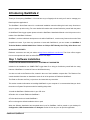
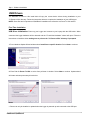
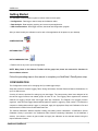
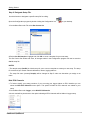
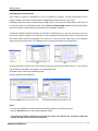
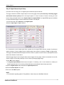
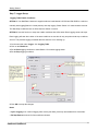
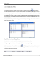
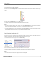
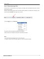
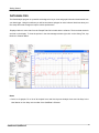
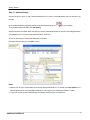
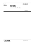
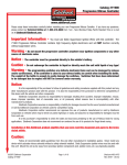
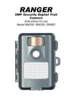
Edelbrock QwikData 2
Quick Start Guide
This QwikData 2 QwikStart guide is a condensed installation manual, outlining the basic setup functions to get your
data acquisition system up and running.
For more detailed information and to better familiarize yourself with the power of QwikData 2 Data Logger System,
please review the QwikData 2 Installation Manual and the Help Menu included in your software.
#63-91270QS
Contents
EDELBROCK QWIKDATA 2 QUICK START MANUAL
2
1 Step 1. Software
...................................................................................................................................
2
Installation
2 USB Drivers ................................................................................................................................... 3
3 Getting Started
................................................................................................................................... 4
CONFIGURATION
..........................................................................................................................................................
Step 2. Designate
.........................................................................................................................................................
Setup File.
Step 3. Register
.........................................................................................................................................................
LCU
Step 4. Set.........................................................................................................................................................
Outing Data
Step 5. Creating
.........................................................................................................................................................
(edit) Calibrations
Channel Parameters
.........................................................................................................................................
Importing Calibrations
.........................................................................................................................................
Calibrating in Manual
.........................................................................................................................................
ADC Count
Calibrating from .........................................................................................................................................
Sensor Output
Step 6. Digital
.........................................................................................................................................................
Channel Input Setup
Step 7. Logger
.........................................................................................................................................................
Set-up
Logging Table Enable
.........................................................................................................................................
Conditions
Logging Table Channel
.........................................................................................................................................
Setup
USB COMMUNICATION
..........................................................................................................................................................
Step 8. Open
.........................................................................................................................................................
the Comms Display Window
Step 9.Sending
.........................................................................................................................................................
a Config to the LCU
Step 10. Downloading
.........................................................................................................................................................
Logged Data
DATA ANALYSIS
..........................................................................................................................................................
Step 11. Add
.........................................................................................................................................................
New Outing
Step 11A..........................................................................................................................................................
Replace Outing
Step 12. Open
.........................................................................................................................................................
a Time Plot
Step 12A..........................................................................................................................................................
Open a Distance Plot
Harness Details
..........................................................................................................................................................
Suggested
.........................................................................................................................................................
Harness Routing
#91290 Basic
.........................................................................................................................................................
Analog Harness Details
#91294 Advanced
.........................................................................................................................................................
Thermocouple Harness Details
#91291 Advanced
.........................................................................................................................................................
Analog Harness Details
Pre Outing Check-List
..........................................................................................................................................................
Qwikdata 2 Tech
..........................................................................................................................................................
Support
User Notes ..........................................................................................................................................................
4
5
6
7
8
9
10
12
13
14
15
15
16
17
17
18
19
20
21
22
23
24
25
26
27
30
33
36
37
38
1
Introducing QwikData 2
Thank you for acquiring QwikData 2. You now have at your fingertips all the tools you'll need to manage your
Data Acquisition applications!
The QwikData 2 Quick Start manual is a condensed installation manual outlining the basic setup functions to
get your system up and running. For more detailed information and to better familiarize yourself with the power
of QwikData 2 Data Logger system please review the QwikData 2 Installation Manual or the Help menu on the
toolbar of the QwikData 2 Software.
QwikData 2, and the individual development tools within QwikData 2, contain many features that make Data
Acquisition a breeze. If you have any questions or issues with QwikData 2, you can contact our QwikData 2
Technical Hotline at 800-416-8628 from 7:00 am to 5:00 pm PST Monday thru Friday. After Hours and
weekends 310-525-8978.
Edelbrock customers can now join others at http://forums.edelbrock.com/forums/ The forum offers support
from current experienced users as well as Edelbrock Tech Reps.
Step 1. Software Installation
*COMPUTERS RUNNING WINDOWS 64 BIT SYSTEMS NOT SUPPORTED
Included in the installation is a SAMPLE.DAT logger data file to help you familiarize yourself with the many
features of QwikData 2. Located in Power to Win\Data directory.
You also can refer to the Read me files, located in the root of the installation compact disc. The Read me files
contain detailed information on installation issues for all of the products in Edelbrock QwikData 2.
The Read me files are text files (*.txt) and can be viewed with any text editor.
This section contains information on installing QwikData 2 to your computer. It is recommended that you check
the section on System Requirements before installing this product.
1. Install the QwikData 2 Software disc in your CD drive.
2. Double click on Install Edelbrock QwikData 2.
3. Follow the directions to install QwikData 2.
4. Do not change the default installation drive or path.
When the Software Installation has completed three Icons for QwikData 2 will be posted on your desktop for
Configuration, USB Communication and Analysis. Double click on any icon to open the application.
Edelbrock QwikData 2
2
Step 1. Software Installation
USB Drivers
The QwikData 2 Power to Win install disk will copy the current device drivers during installation to your
"C:\Power to Win" directory. Follow the instructions below to complete the installation of your USB drivers.
NOTE: Some files and components of QwikData 2 installation are referred to as Power To Win and EFI.
First Time Installation
USB Driver Initialization: Power up your Logger and connect to your Laptop with the USB cable. When
connected the logger hardware will be detected and the "Found New Hardware" wizard will open. Follow the
instructions to install the driver making sure to point to the "C:\Power to Win" directory if prompted.
1. From Hardware Update Wizard window select Install from a specific location. Select Next to continue.
2. Enter Path: C:\Power To Win or select from pull down in window. Select Next to continue. Update wizard
will locate and setup necessary driver device.
Notes
· Drivers can only be installed or updated when the logger is powered up and connected to the USB port.
Edelbrock QwikData 2
3
USB Drivers
Getting Started
The QwikData 2 data acquisition system is broken down into three parts:
· Configuration - Data logger, channel setup and calibration editor.
· Data Analysis - Data analysis, graphing, and custom reports application.
· USB Communication - Data logger monitor, download and configuration program.
After you have loaded your software Icons for each of the application will be placed on your desktop.
CONFIGURATION -
DATA ANALYSIS -
DATA COMMUNICATION · Double click on any Icon to open the application.
NOTE: Many items in the Software Toolbars will be grayed out, these are reserved for functions in
future software releases.
Follow the preceding steps in this manual to complete your QwikData 2 Data System setup.
CONFIGURATION
The Configuration module is for managing all of your data logger setups.
Setup files contain a Channel Logging Table, Outing Information, Channel Data and Channel Calibrations, for
up to 10 different cars.
A variety of tools are provided for setting up your data logger. The setup screens have been designed to list
the various logger functions into related groups for ease of use. The Logging Table organizes the selected
channels for logging, sample rates and logger start stop conditions. The Register LCU (Logger) function
organizes setup files and logged data download paths for specific Loggers by serial number. This allows the
computer to distinguishes which Logger is connected, apply the appropriate Setup and Calibration files and
determines the location for the Downloaded Data Files.
The Channel Calibration Window simplifies creating and editing sensor calibrations. A QwikData 2 Sensor
Calibration Library is provided in the Calibration Editor Window containing Calibrations for all QwikData 2
sensors. Just choose a sensor by part number and apply the calibration to the selected channel using the
Import Calibration function.
Edelbrock QwikData 2
4
Getting Started
Step 2. Designate Setup File.
Use this function to designate a specific setup file for editing.
Open the Configuration program by double clicking the Configuration Icon
on your desktop.
1. On the Menu Bar under File select Set Current Car.
2. Select Car #01-Sample to highlight and click OK to set as a template for your new setup.
The Set Current Car window will close, all changes made in the Configuration program will now be saved to
Car 01 setup file.
NOTES
* The sample setup (Car#01) is a blank setup for you to use as a template to create your own setup. The setup
file contains all your sensor channel calibrations, names, logging table etc.
* The setup file name (currently Sample) will be changed in Step 5 under car data when you assign a car
name.
Hide ECU Channels
· To further simplify your setup procedure, if you are using your logger without an ECU interface you can
select the Hide ECU Channels menu option. This option will hide all ECU channels not related to your
setup.
1. On the Menu Bar under Logger, select Hide ECU Channels.
A check mark will be placed next to the option indicating all ECU channels will be hidden in logger setup.
Edelbrock QwikData 2
5
Getting Started
Step 3. Register LCU
In order for a Logger to recognize a specific setup file (CAR ##), the LCU (Logger) serial number must be
registered and a download path specifying the file location for downloaded race data must be entered. The
serial number can be found on a sticker on the housing of the Logger and also appears on the status bar of the
USB Comms screen of your computer when connected.
1. On the Menu Bar under File, click Register LCU's.
2. Enter the LCU(Logger) serial number and logger download path next to the Car setup you are working
with.
3. You can browse for a existing download path by clicking the [...] button.
Select the new path or enter the name in the path text box. If the download path does not exist you will be
prompted to have it created for you.
4. Click OK to save changes.
Notes
· 01 Represents Car#01 setup.
· Create recognizable file names like Car description or event name eg: C:\Power to Win\Data\Mustang or
C:\Power to Win\Data\Raceway Park
· Unused serial number fields should be set to zero.
· Data downloaded from an unregistered LCU will default to Car 01 Download Path
· If a Logger Serial # is not entered Logger setup will default to Car 01 Setup.
Edelbrock QwikData 2
6
Getting Started
Step 4. Set Outing Data
This function allows the user to enter specific Outing Data that will be stored with each downloaded data set.
This information also helps identify each logger outing when browsing for specific data files with the Analysis
program. The comments should be updated prior to each outing and can be edited in the Analysis program
post downloads.
1. On the menu bar under Logger, click Outing Data.
2. Enter the Driver and Car Names.
3. Type in any text Comments for the data set in Line 1 and Line 2.
4. Enter track Name and Length.
Beacon Mask is reserved for options in future software releases.
5. Click OK to save changes.
Notes
· The Outing Data is saved and will be downloaded as part of each Logger Data set.
· Outing Data can be edited in the Analysis program.
Setup Sheet
This function allows the user to enter vehicle, weather and track specific setup data that will be stored with
each downloaded data set.
1. On the menu bar under Logger, click, Setup Sheet.
2. Type in any text Comments for the data set.
3. Click OK to save or Print to print a hard copy.
Notes
The Setup Sheet is saved and will be downloaded as part of each logger data set.
Edelbrock QwikData 2
7
Getting Started
Step 5. Creating (edit) Calibrations
When calibrating a sensor you define a set of points by specifying x and y coordinates. A minimum of two
points are required to create a linear calibration curve. Ideally the calibration should include two points close to
the maximum and minimum raw values. Non-Linear type calibrations(Interpolation) for temperature sensors
require more data points.
A pressure transducer may have a output signal range of .5 volts to 4.5 volts. The LCU converts this voltage to
a Binary representation. QwikData 2 is a 12 bit system with a maximum resolution of 4096 counts(bits). At 0.0
psi the sensor output is .5 volts or 410 bits, at 100 psi the sensor output is 4.50 volts or 3685 bits. A sensor
calibration refers to voltage output as X and the bit count as Y.
A complete understanding of Sensor Calibration is not necessary. The Import Sensor Calibration
function is a simple direct procedure for calibrating most QwikData 2 sensors.
Three procedures for creating Sensor Calibrations are available in QwikData 2. Refer to the underlined links
below for more information.
1. Importing Calibrations. The simplest most direct procedure for creating sensor calibrations is to import
calibrations from a list of sensors organized by part number and accessed with the Import function in the
sensor calibration window.(Microsoft Office Excel must be loaded on computer to function)
2. Calibrating in Manual ADC Count. Follow the Manual ADC Count procedure to manually enter the X and
Y sensor calibration points from the keyboard for you sensors. This is a useful procedure if you are using a
sensor supplied with specific calibration information.
3. Calibrating from Sensor Output. If the output of the sensor is dependant on how it is installed, (a linear
potentiometer used to measure damper movement or throttle position for example) then it is easier to use
direct sensor readings from the logger for the X calibration point while communicating with the logger to
calibrate the channel.
Notes
· It is helpful to first assign Channel names and setup graph scaling's in Channel Parameters for the channels
you will be calibrating.
· Channel names must be entered under Channel Parameters in the Calibration Window. The Channel
Scales, Color and Decimal Points may also be edited in the Channel Data Window.
· Microsoft Office Excel must be loaded in computer for Import Calibration Window to open properly.
Edelbrock QwikData 2
8
Getting Started
Channel Parameters
Channel Parameters are what defines a particular Channel; the Channel Name, Unit Definition, Resolution,
Filters if necessary, and Graphic Scaling that the channel will be displayed on in Analysis.
1. Under Channels on the menu bar select Edit Calibration, the Calibration Window will open (Fig.1).
2. From the Calibration Window menu bar under Channel, click Select Channel or Ctrl L. Choose the
channel for calibrating from the list (Fig.2).
Fig.1
Fig.2
3. From the calibration window menu bar under Channel select Channel Parameters.
4. The channel parameter editor window will display the parameters for the selected channel (Fig.3).
Fig.3
5. Select Name and enter a name for the channel.
6. Select Units and enter the units that you want the sensor data displayed in.(psi ,inHg, Deg F. etc.)
7. Select Graphics and enter the number of decimal places to which the channel data is displayed.
8. Auto Scale sets the channels upper and lower graph scales automatically based on recorded data values.
9. Select Color and choose a default color for the channel from the defined palette.
10. Click OK to save changes. Repeat steps 2 thru 10 for each sensor.
Notes
· Graph Scales will be applied to Calibration Window graph and Analysis Channel graph.
· Graph scaling can be further adjusted in Analysis program.
· Dashboard drop down feature is reserved for future software releases.
Edelbrock QwikData 2
9
Getting Started
Importing Calibrations
Most users find this calibration procedure the simplest and most direct. Follow these functions to Import
calibrations for your sensors.
· Be sure to assign channel names and edit Channel Parameters before creating calibrations. Un-named
channels will be listed as Logger location or ANA##.
1. From the menu bar under Channels select Edit Calibrations(Ctrl+C), this will open the calibration window
(Fig1).
2. In the calibration window menu bar under channel click Select Channel.
Fig.1
3. From the Analog Channels window double click the channel you want to calibrate (Fig.2).
4. From the menu bar under file select Import.
Fig.2
Edelbrock QwikData 2
10
Getting Started
5. Select the tab to display the sensor type i.e: Pressure,Temperature, Lambda, Misc..
· Sensor calibrations are listed by part number or description and are available in various ranges and
units.
6. Double Click on a sensor name to select (Fig.3).
Fig.3
· The calibration window will reopen with the selected calibration applied (Fig.4).
Fig.4
7. Repeat steps 2 thru 6 for next sensor.
8. To save changes exit Calibration Window or under File on the menu bar select Save Changes .
Edelbrock QwikData 2
11
Getting Started
Calibrating in Manual ADC Count
Follow the Manual ADC Count procedure to manually enter calibration points from the keyboard for your
sensors. This is a useful procedure if you are using a sensor supplied with specific calibration information. Be
sure to edit the selected channels parameters before creating a calibration.
1. Open the calibration window and select the channel you want to calibrate.(Fig.1)
Fig.1
2. On the calibration window menu under Channel select Manual ADC Count, a check should appear.
3. On the Calibration window Menu Bar under Calibrate, select Insert Value.
4. Enter the Y Value (Units)
Hit OK
5. Enter the X Value (Bits)
Hit OK
The graphic display is updated as points are added to the calibration grid. If calibration points exceed graph
adjust graph scaling in step #7 of Parameters.
6. Repeat step 2 to enter more calibration points if necessary.
7. Enter a Calibration Type.
8. Close to save changes.
Edelbrock QwikData 2
12
Getting Started
Calibrating from Sensor Output
If the output of a sensor is dependant on how it is installed; for example, a linear potentiometer used to
measure damper movement or throttle position Calibrating from Sensor Output is very useful.
Calibrating using direct sensor readings requires USB Comms. to be open and online with the LCU and LCU
12 volt power ON. In the Calibration window under Channel the Manual ADC Count must also be unchecked.
Be sure to edit the selected channels parameters before creating a calibration.
1. Open the Calibration window and select the channel for calibrating (Fig.1). If you are connected to your LCU
the real-time channel reading in the status bar is active showing the current output from the selected sensor
and can be used to monitor the response of the sensor as it moves. The lower right corner of the calibration
window should read Connected. The calibration points in the grid are plotted on the graph(Fig.2).
Fig.1
Fig.2
2. Hit the Enter Key, a window for Y Value should open(Fig.3), set sensor to known value for Y, enter value of
Y in the window and hit Enter Key again to record calibration point.
3. Repeat steps to record more calibration points.
4. Close window to save Calibration.
Fig.3
Notes
· You can use the Del key to delete unwanted calibrations points for the selected grid cell.
· Use the Edit Value menu to edit existing calibration points.
· The first four available channels on the channels list are LCU internal, the connection status will
always read Not Connected for these channels.
Edelbrock QwikData 2
13
Getting Started
Step 6. Digital Channel Input Setup
Use this function to setup your LCU digital inputs as RPM and speed channels.
The logger references a RPM or Speed input for both the logging criteria (not necessary if activating logger
with Switch Activate option) and for the engine logbook. In order for these to function correctly you must
have at least one digital channel set to System Speed or System RPM. If no digital RPM inputs are available
for System RPM the logger must be enabled with a switch. See Step #8.
1. On the menu bar under Channels, click Digital Inputs.
2. Select a Input Type for Digital channel.
3. If connected to a tach output signal from a ignition box for engine RPM enter the number of pulses per
engine revolution. If using a trigger wheel or flying magnet enter number of magnets or Teeth on trigger wheel.
The logger calculates distance and speed from the number of pulses received from the wheelspeed sensors
and the tire diameter of each wheel.
4. Select trigger edge for sensor signal. Most sensors trigger off rising edge. If data is inconsistent or has drift,
sensor air gap is correct and pulses per rev are correct try changing trigger edge.
5. Click OK to save changes.
· The System Speed Button allows users the option of combining two or more channels to create your
System Speed channel. If not running a Wheel Speed Input skip System Speed setup procedure.
1. Open the Digital Inputs setup and press the System Speed button.
2. Select the Active Inputs to be used.
3. Pick one of the Mode options.
NOTE
· For information regarding Ignition Timing Monitor, Interval setup see QwikData 2 Manual.
Edelbrock QwikData 2
14
Getting Started
Step 7. Logger Set-up
Logging Table Enable Conditions
OPTION 1: Your QwikData 2 harness is supplied with two leads labeled LOG-SW and SW-GND for a switch to
manually start logging(Switch in closed position) and stop logging. Select Switch 3 for manual switch override.
The Start Stop Conditions have no effect when the Switch 3 is active.
OPTION 2: Use this function to setup the enable conditions that define when Data Logging starts and stops.
Data Logging will start when either of the start conditions are met but will only stop when both stop conditions
are met. This prevents logging unwanted data like when the car is warming up.
1. On the menu bar under Logger, click Logging Table.
2. Click on the Enable tab.
3. Set the Start logging conditions or select Switch 3 for manual logging switch.
4. Set the Stop logging conditions.
5. Click OK to accept the changes.
Notes
· Cyclic Logging is for continual logging after memory has filled, previously stored data will be overwritten.
· Pit Stop Beacon reserved for future software releases.
Edelbrock QwikData 2
15
Getting Started
Logging Table Channel Setup
Use this function to enable a channel for logging and setup the sample rates for each of the channels that you
want to log.
1. On the menu bar under Logger, click Logging Table.
The available channels and current sample rates will be displayed (Fig1).
Fig.1
Fig.2
2. Double-click on the channel you want to log and set the sample rate on.
3. Select a sample rate from the available options window (Fig.2).
4. Click OK.
The LCU has a fixed amount of logging memory. If you choose to log channels at a high rate you will reduce
the total number of channels that you can log. If a channel does not vary much during a lap, for example;
temperatures, pressures then choose slower logging rates.(Typical Example: Temperatures-5Hz, Pressures
20Hz, RPM 20Hz, Suspension movement 50Hz) Note: 20Hz equals 20 samples per second.
5. Repeat step 3 for the next channel.
6. Click OK to accept the changes.
Notes
· The number of channels enabled and the total logging time is updated each time you make a change.
· Hold the Ctrl key and select multiple channels to change more than one channel at a time.
· The Channel Logging Rate of LCU Battery also controls the refresh rate of the Comms screen. It is
recommended to keep this rate at 50Hz or Higher.
Edelbrock QwikData 2
16
Getting Started
USB COMMUNICATION
To open the Communication program from your desktop click the USB Comms Icon
on your desktop.
The USB Communications module is the main interface between your computer and Data logger. It features
an advanced user configurable monitor for viewing real time channel data along with tools for downloading
data and sending setups.
The monitor allows the user to create any number of windows to display channel data. Once a screen format
has been defined it can be saved to disk allowing multiple setups to be created and reloaded depending on the
particular application.
A variety of functions are provided for setting up and downloading the data logger. New firmware can also be
loaded from within this module.
Step 8. Open the Comms Display Window
Use this function to open the sample Comms display window included with your software.
1. Plug your Logger into the Laptop with the supplied USB cable and power up the logger.
2. From your desktop Click the USB Comms Icon
. USB Communication program should open and
display a blank window. In the status bar at the bottom of the page ON LINE should be displayed indicating the
computer and logger are communicating.
Edelbrock QwikData 2
17
Getting Started
3. On the Menu Bar under File click Open.
4. Select the file named Settings.nsb. All Comms Window Templates are saved with the file extension type
(*.nsb)
5. Double-click the Settings.nsb file or click OK to open it.
The sample Comms window should open displaying all channels and data.
Notes
· For details regarding modifying the Comms screen see Editing Windows in the USB Communication
section of the QwikData 2 Manual or from Help on your QwikData 2 Software Toolbar.
· For details regarding how to Zero Analog channels see Zero Channels in the USB Communication section
of the QwikData 2 Manual or from Help on your QwikData 2 Software Toolbar.
Step 9.Sending a Config to the LCU
Any time a Set-up File is modified in the Configuration Program it must be loaded in the Logger before the
changes can take effect. Follow these steps to load a Set-up File in the Logger.
1. From USB Comms on the Logger menu, click Send Config.
2. The current setup registered to the LCU(Logger) will be sent to the logger.
A window will display indicating the LCU(Logger) configuration has successfully been updated.
Notes
· You cannot send a new setup to the logger while it is recording data.
Edelbrock QwikData 2
18
Getting Started
Step 10. Downloading Logged Data
Use this function to download data from your logger to your laptop. Once downloaded the data can be viewed
with the Analysis module.
With the Communications program open connect the USB cable between your laptop and LCU(Logger). Verify
communication is ON LINE in lower right corner of screen.
1. On the Logger menu, click Download.
A progress bar will briefly display indicating download progress.
After the download is complete your Setup File is automatically re-loaded.
Notes
· You cannot download the logger while it is still recording data.
· If Logger is empty a window indicating Logger has no data to download will display.
Edelbrock QwikData 2
19
Getting Started
DATA ANALYSIS
The Data Analysis program is a powerful tool designed to let you view and graph information downloaded from
your data logger. Using this software you will become better equipped to make informed decisions about your
race setup and make changes to improve vehicle performance.
Displayed below is some data from the Sample Data file included with the software. The three data channels
are tiled on the display. To view the options in the data manager window right click on the Outing Title, Lap
Number or Channel Name.
Notes
· Ctrl+V to tile graphs. For a list of all Analysis Icons and Hot Keys see Analysis Icons and Hot Keys in the
User Manual or from Help on the toolbar of the QwikData 2 Software.
Edelbrock QwikData 2
20
Getting Started
Step 11. Add New Outing
Use this function to open or add a downloaded data file for review. Downloaded data files are referred to as
Outings.
Open the Data Analysis program by double clicking the Data Analysis Icon
on your desktop.
1. On the Menu Bar under File, click Add Outing.
2. Select the drive and folder where the Outing is located. Downloaded Data File location was designated when
you registered your LCU and set the download path in the Step 4.
3. Click on the outing to read the file details and comments.
4. Double-click the Outing or click OK to open it.
Notes
· Analysis can be set to automatically open the last downloaded data file. For details see Auto Update in the
Data Analysis section of the QwikData 2 Manual or from Help on your QwikData 2 Software Toolbar.
· To prevent crowding in the Data Manager use Replace Outing to open new data files.
Edelbrock QwikData 2
21
Getting Started
Step 11A. Replace Outing
Use this function to replace the current Outing in the File Folder.
1. On the Menu Bar under File, click Replace Outing.
2. Select the drive and folder where the new Outing is located.
3. Click on the Outing to read the file details and comments.
4. Double-click the Outing or click OK to select it.
Notes
· To open a file you've used recently, you can use the Recent File menu list.
· You can use the Add Outing menu to add a new outing to the File Folder for data comparisons.
· Analysis can be set to automatically open the last downloaded data file. For details see Auto Update in the
Data Analysis section of the QwikData 2 Manual or from Help on your QwikData 2 Software Toolbar.
Edelbrock QwikData 2
22
Getting Started
Step 12. Open a Time Plot
Use this function to display the time plot window. This plot is useful for looking at events that are independent
of the position of the track or when a wheel speed input is not available to plot against distance. Selected data
should display.
1. On the Menu Bar under View, click Time Plot.
The time plot window will open and display a graph of the channels loaded in the file folder plotted against
time. The scale for the current channel is displayed on the left axis and additional channel information is
displayed at the top of the graph.
Select the Add Channels Icon
from the menu bar to display a list of logged channels to display on the
graph.
2. Move the cursor horizontally to a point of interest.
3. Right click to open the zoom and scroll popup menu.
The channel numerical data for the current cursor location is displayed in the upper right corner of the window
and will update as the cursor is moved.
Notes
· Clicking on a channel in the file folder makes it the new current channel.
· Right click over the left axis to open the channel scaling popup menu.
Edelbrock QwikData 2
23
Getting Started
Step 12A. Open a Distance Plot
Use this function to open the distance plot window. Distance Plot requires wheel speed and distance
channel logging. This plot is useful for looking at events that relate to actual track position. By overlaying
data from several laps you can compare visually the difference in performance at any point on the track.
1. On the Menu Bar under View, click Distance Plot.
The distance plot window will open and display a graph of the channels loaded in the file folder plotted against
distance. The scale for the current channel is displayed on the left axis and additional channel information is
displayed at the top of the graph.
Select the Add Channels Icon
from the menu bar to display a list of logged channels to display on the
graph.
2. Move the cursor horizontally to a point of interest.
3. Right click to open the zoom and scroll popup menu.
The channel numerical data displayed in the windows upper right corner for the current distance will update as
the cursor is moved.
Notes
· Distance Plot requires wheel speed and distance channel logging.
· Clicking on a channel in the file folder makes it the new current channel.
· Right click over the left axis to open the channel scaling popup menu.
Edelbrock QwikData 2
24
Getting Started
Harness Details
This section covers the Logger Harness details. The QwikData 2 Data Acquisition System is available in three
configurations; Basic, Advanced Thermocouple and
Advanced Analog . Harness schematics, pin-out
designations and connector details for each system are available in this section. These details may be useful
when setting up your QwikData 2 system.
To make the installation as easy as possible, the wiring harness provided is completely assembled with
connectors that mate to the supplied sensors. Each sensor is connected to the QwikData 2 unit by simply
mating the appropriate connectors.
Route the wiring harness as needed to make connections to the installed sensors. Avoid paralleling Data Log
wires with any ignition wiring (primary or secondary) To connect the circular connectors on the wiring harness
to the sensors, push the mating connectors firmly together and then turn the locking ring clockwise to lock the
connectors together.
Refer to Suggested Harness Routing in the Harness Detail Section for assistance with routing you harness.
With some installations it may be necessary to re-pin the Logger Connector in order to accommodate sensor
location and available sensor input types. In these situations it should only be necessary to move the Analog
Signal or Digital Signal wires in the Logger connector. The Sensor power and ground wires are all common. To
release the pins in the Logger Connector simply depress the single white rectangular shape button on the
Logger Connector. Re-locate pins as necessary in connector then depress pair of white rectangular buttons on
opposite side of connector to lock pins.
Labels on harness sensor connections match channel names in setup.
BASIC SYSTEM HARNESS PART #91290
The Basic System includes a single harness with 8 analog, 4 thermistor type temperature sensor (or analog
inputs depending on Logger card configuration), 1 Tach Input, 1 frequency(digital) sensor connectors and 1
programmable switched output that all terminate at the 34 pin connector on the LCU.
ADVANCED THERMOCOUPLE HARNESS PART #91294
The Advanced Thermocouple System includes two harnesses; the Basic System Harness and a second
harness with 4 additional Analog sensor connectors, 2 frequency(digital) sensor connectors, 8 thermocouple
connectors and a additional programmable switched output that terminate at the 26 pin connector on the
Logger.
ADVANCED ANALOG HARNESS PART #91291
The Advanced Analog System includes two harnesses; the Basic System Harness and a second harness with
12 analog sensor connectors, 2 frequency(digital) connectors and a additional programmable switched output
that terminate at the 26 pin connector on the Logger.
Edelbrock QwikData 2
25
Getting Started
Suggested Harness Routing
Edelbrock QwikData 2
26
Getting Started
#91290 Basic Analog Harness Details
Edelbrock QwikData 2
27
Getting Started
#91290 Basic Harness Schematic
Edelbrock QwikData 2
28
Getting Started
#91290 Basic Analog Harness LCU Connector pin assignments
34 Pin LCU Connector
PIN
1
2
3
4
5
6
7
8
9
10
11
12
13
14
15
16
17
WIRE COLOR
BLK/ORG
BLK/YEL
BLK/RED
BLK/WHT
BLK/BLU
BLK/VLT
BLK/GRN
VLT/WHT
TAN/WHT
BLK/GRAY
WHT/BLU
BROWN
LT BLU
DK GRN
N/C
BROWN
PNK/BLK
FUNCTION
(Ch I.D)
ANALOG 1
(0004)
ANALOG 2
(0005)
ANALOG 3
(0006)
ANALOG 4
(0007)
ANALOG 5
(0008)
ANALOG 6
(0009)
ANA/TEMP 7
(0010)
ANA/TEMP 8
(0011)
ANA/TEMP 9
(0012)
ANA/TEMP 10
(0013)
ANALOG 11
(0014)
ANALOG 12
(0015)
DIG 1
(0064) (TACH INPUT)
DIG 2
(0065)
DIG 5
(0068) LOW RESOLUTION
SW 3
12V SWITCHED
PIN
18
19
20
21
22
23
24
25
26
27
28
29
30
31
32
33
34
WIRE COLOR
BLK/WHT/ORG
LT GRN
N/C
BLK/WHT/ORG
GRAY
GRAY
RED
N/C
BLK/WHT/ORG
BLK
N/C
N/C
N/C
N/C
N/C
N/C
BLK
FUNCTION
SENSOR GND
SWITCHED OUT 1
RXD(FROM ECU
SENSOR GND
VREF
VREF
REG 12V
TXD(TO DASH)
SENSOR GND
BATTERY GND
BATTERY GND
#91290 Basic Analog Harness parts and vendor details
QTY
DESCRIPTION
MANUFACTURER
1
34 POSITION SUPER SEAL HOUSING
AMP
MANUFACTURER
PART NUMBER
2-1437285-3
26
SOCKET TERMINAL, SUPER SEAL
AMP
3-1447221-5
1
HOUSING, METRI-PACK 150 SERIES
DELPHI
12110293
3
TERMINAL, FEMALE METRI-PACK 150 SERIES
DELPHI
12084200
3
CABLE SEAL, METRI-PACK 150 SERIES
DELPHI
12048087
1
TPA, METRI-PACK 150 SERIES
DELPHI
12052845
1
HOUSING, METRI-PACK 150 SERIES
DELPHI
12129615
3
CAVITY PLUG, METRI-PACK 150 SERIES
DELPHI
12059168
1
TPA, METRI-PACK 150 SERIES
DELPHI
12052845
13
EN3 MINI WEATHERTIGHT CONNECTOR
SWITCHCRAFT
EN3C4FC
Edelbrock QwikData 2
29
Getting Started
#91294 Advanced Thermocouple Harness Details
Edelbrock QwikData 2
30
Getting Started
#91294 Advanced Thermocouple Harness Schematic
Edelbrock QwikData 2
31
Getting Started
#91294 Advanced Thermocouple Harness LCU Connector pin assignments
26 Pin LCU Connector
PIN
1
2
3
4
5
6
7
8
9
10
11
12
13
WIRE COLOR
GRY/BLK
RED/YLW
WHT/BLU
WHT/VLT
VLT/YEL
WHT/ORG
YEL
YEL
YEL
YEL
YEL
YEL
YEL
FUNCTION
DIG 3
DIG 4
ANALOG 13
ANALOG 14
ANALOG 15
ANALOG 16
K-TYPE 1
K-TYPE 2
K-TYPE 3
K-TYPE 4
K-TYPE 5
K-TYPE 6
K-TYPE 7
(Ch I.D)
(0066)
(0067)
(0016)
(0017)
(0050)
(0051)
(0052)
(0053)
(0054)
(0055)
(0056)
(0057)
(0058)
PIN
14
15
16
17
18
19
20
21
22
23
24
25
26
WIRE COLOR
YEL
RED
RED
RED
RED
RED
RED
RED
RED
BLK
N/C
DK GRN
N/C
FUNCTION
(Ch I.D)
K-TYPE 8
(I.D0059)
K-TYPE NEG 1
K-TYPE NEG 2
K-TYPE NEG 3
K-TYPE NEG 4
K-TYPE NEG 5
K-TYPE NEG 6
K-TYPE NEG 7
K-TYPE NEG 8
K-TYPE SHIELDS GRND
SWITCHED OUT 2
FREQ 6
(I.D0069) LOW
RESOLUTION
#91294 Advanced Thermocouple Harness parts and vendor details
QTY
DESCRIPTION
MANUFACTURER
1
26 POSITION SUPER SEAL HOUSING
AMP
MANUFACTURER PART
NUMBER
2-1437285-2
25
SOCKET TERMINAL, SUPER SEAL
AMP
3-1447221-5
1
HOUSING, METRI-PACK 150 SERIES
DELPHI
12129615
3
TERMINAL, MALE METRI-PACK 150 SERIES
DELPHI
12077628
3
CABLE SEAL, METRI-PACK 150 SERIES
DELPHI
12048087
1
TPA, METRI-PACK 150 SERIES
DELPHI
12052845
8
SUBMINI CONNECTOR ALLOY CODE K
OMEGA
SMPW-K-F
6
EN3 MINI WEATHERTIGHT CONNECTOR
SWITCHCRAFT
EN3C4FC
Edelbrock QwikData 2
32
Getting Started
#91291 Advanced Analog Harness Details
Edelbrock QwikData 2
33
Getting Started
#91291 Advanced Analog Harness Schematic
Edelbrock QwikData 2
34
Getting Started
#91291 Advanced Analog Harness LCU Connector pin assignments
26 Pin LCU Connector
PIN
1
2
3
4
5
6
7
8
9
10
11
12
13
WIRE COLOR
GRY/BLK
RED/YLW
WHT/BLU
WHT/VLT
VLT/YEL
WHT/ORG
LYLW/BLK
LT GRN
DK BLU
DK GRN/WHT
VLT
TAN/WHT
WHT/BRN
FUNCTION
(Ch I.D)
DIG 3
(I.D0066)
DIG 4
(I.D0067)
ANALOG 13
(I.D0016)
ANALOG 14
(I.D0017)
ANALOG 15
(I.D0050)
ANALOG 16
(I.D0051)
ANALOG 17
(I.D0052)
ANALOG 18
(I.D0053)
ANALOG 19
(I.D0054)
ANALOG 20
(I.D0055)
ANALOG 21
(I.D0056)
ANALOG 22
(I.D0057)
ANALOG 23
(I.D0058)
PIN
14
15
16
17
18
19
20
21
22
23
24
25
26
WIRE COLOR
RED/BLU
N/C
N/C
N/C
N/C
N/C
N/C
N/C
N/C
N/C
N/C
DK GRN
N/C
FUNCTION
(Ch I.D)
ANALOG 24 or CARD (I.D0059)
SWITCHED OUT 2
FREQ 6
RESOLUTION
(I.D0069) LOW
#91291 Advanced Analog Harness parts and vendor details
QTY
DESCRIPTION
MANUFACTURER
1
26 POSITION SUPER SEAL HOUSING
AMP
MANUFACTURER PART
NUMBER
2-1437285-2
16
SOCKET TERMINAL, SUPER SEAL
AMP
3-1447221-5
1
HOUSING, METRI-PACK 150 SERIES
DELPHI
12129615
3
TERMINAL, MALE METRI-PACK 150 SERIES
DELPHI
12077628
3
CABLE SEAL, METRI-PACK 150 SERIES
DELPHI
12048087
1
TPA, METRI-PACK 150 SERIES
DELPHI
12052845
14
EN3 MINI WEATHERTIGHT CONNECTOR
SWITCHCRAFT
EN3C4FC
Edelbrock QwikData 2
35
Getting Started
Pre Outing Check-List
To help verify your car is properly setup for each session use the following guide for setting up your data logger
system.
1. Open the Configuration program
2. Set Current Car for setup.
3. Register the Logger serial number with Setup file and download path.
4. Calibrate Sensors as necessary if any sensor changes have been made.
5. Verify Logging Table settings, channels for logging, channel sample rates and enable criteria.
6. Update Outing Data file with driver and comments information.
7. Update Setup sheet.
8. Open USB Communication program.
9. Open the Comms Display Window.
10. Send Config file to Logger.
11. Verify sensor functions and channel values.
Edelbrock QwikData 2
36
Getting Started
Qwikdata 2 Tech Support
For further information, Technical support, updates and free downloads please see the Edelbrock web site and
QwikData 2 Support Forum:
Edelbrock Toll-Free Tech Line: 800-416 8628
7am-5pm PST, Monday-Friday
Web site:
Edelbrock.com - Automotive - Data Acquisition- QwikData 2
Edelbrock Forum: QwikData 2
Edelbrock Corporation
2700 California St
Torrance CA. 90503
Edelbrock QwikData 2
37
Getting Started
User Notes
Edelbrock QwikData 2
38
D ATA A C Q U I S I T I O N
www.edelbrock.com
Edelbrock Corporation
Torrance, California 90503
USA
For more information in print or on CD call: 1-800-FUN-TEAM or go to website
Factory Tech Line: 1-800-416-8628 from 7am-5pm PST, Monday-Friday
Headquarters: 1-310-781-2222 from 8am-5pm PST, Monday-Friday
Tech support: [email protected]
Brochure #00879
©2009 Edelbrock Corporation
Printed Oct 2009